EP3296826A1 - Verfahren und anordnung zur inbetriebnahme von regel- und steuergeräten für eine gebäudeautomatisierung - Google Patents
Verfahren und anordnung zur inbetriebnahme von regel- und steuergeräten für eine gebäudeautomatisierung Download PDFInfo
- Publication number
- EP3296826A1 EP3296826A1 EP17189461.1A EP17189461A EP3296826A1 EP 3296826 A1 EP3296826 A1 EP 3296826A1 EP 17189461 A EP17189461 A EP 17189461A EP 3296826 A1 EP3296826 A1 EP 3296826A1
- Authority
- EP
- European Patent Office
- Prior art keywords
- control
- mobile communication
- communication terminal
- rsg2
- rsg1
- Prior art date
- Legal status (The legal status is an assumption and is not a legal conclusion. Google has not performed a legal analysis and makes no representation as to the accuracy of the status listed.)
- Granted
Links
Images


Classifications
-
- G—PHYSICS
- G05—CONTROLLING; REGULATING
- G05B—CONTROL OR REGULATING SYSTEMS IN GENERAL; FUNCTIONAL ELEMENTS OF SUCH SYSTEMS; MONITORING OR TESTING ARRANGEMENTS FOR SUCH SYSTEMS OR ELEMENTS
- G05B19/00—Program-control systems
- G05B19/02—Program-control systems electric
- G05B19/04—Program control other than numerical control, i.e. in sequence controllers or logic controllers
- G05B19/042—Program control other than numerical control, i.e. in sequence controllers or logic controllers using digital processors
- G05B19/0423—Input/output
- G05B19/0425—Safety, monitoring
Definitions
- the invention relates to a method and an arrangement for starting up a control and control device for field devices for building automation.
- HVAC heating, ventilation or air conditioning
- the object is achieved by a method for starting up a control and control device for field devices for a building automation, wherein between the control and control device and a mobile communication terminal of a user a communication connection is created; wherein the mobile communication terminal is set up to query data points of the regulation and control device via the communication connection and to check their respective state, wherein a data point represents the state of a parameter of a field device; and wherein the mobile communication terminal is further configured to transmit the respective state of the data points via a further communication link to a central location.
- Mobile communication terminals eg smartphones, tablet computers
- control and regulating devices eg controllers
- central points eg control center, building management, building management system, server
- the mobile communication terminal is set up via an installed software program (eg App) to interrogate data points of the control and regulation device via the communication connection and to check their respective status.
- the app ie the software program
- the app is installed eg via a URL from the Internet (Android: Play Store, iOS: AppStore) on the mobile communication terminal.
- the transmitted data points can be further analyzed, in particular the project progress during commissioning of the control and control devices can be logged and tracked and the progress can be checked.
- a data point is a designation for an input or output function consisting of all associated information (which includes the actual value and / or state and parameters (properties and attributes), eg signal type and signal characteristic, measuring range, unit and state texts) fully describe their meaning (semantics) and which is identified via a data point address and / or a user address.
- Commissioning is understood to mean, in particular, the setting of a system, a system or a machine. That in particular, measures and actions (eg configuration, parameterization, optimization and test) that are necessary to make a machine or plant operational or ready for use.
- measures and actions eg configuration, parameterization, optimization and test
- a commissioning includes measures and activities that are carried out after the installation of the hardware or after the installation of the software for setting up and testing the product / system.
- a field device is understood in particular to be sensors and actuators. States of the field devices are mapped in the rule and controller (e.g., controller) to corresponding data points.
- a first advantageous embodiment of the invention is that the location of the control and regulation device is communicated in a building by a corresponding position signal to the mobile communication terminal.
- the control unit or controller for the control of HVAC or room automation applications is mounted in a room in a decentralized location and often difficult to find, usually in the false ceiling, under a window panel, or in the false floor). This makes it more difficult for the commissioning engineer to find (localize) the regulating and control device or the controller.
- the position signal for example, a commissioning engineer is led directly to the point of installation of the control and regulating device in a room. Unnecessary time to search for the control and regulating device is eliminated.
- the position signal can be satellite-based (eg via GPS) or provided by an Indoor Positioning System (IPS).
- the mobile communication terminal eg smartphone
- IPS Indoor Positioning System
- a further advantageous embodiment of the invention is that the position signal is sent from the control and control unit.
- the position signal may e.g. by a small transmitter (e.g., Beacon, iBeacon) located in or on the controller.
- the transmitter is based on Bluetooth Low Energy (BLE).
- a further advantageous embodiment of the invention lies in the fact that the communication between the regulating and control device and the mobile communication terminal takes place via a wireless connection (for example WLAN, NFC, Bluetooth).
- a wireless connection for example WLAN, NFC, Bluetooth.
- wireless communication networks are already installed in buildings or can easily be retrofitted or realized.
- Mobile communication terminals e.g., smartphones
- a further advantageous embodiment of the invention is that the wireless connection between the control and control device and the mobile communication terminal via a device installed by the user on the control and regulating device (for example, a radio module) takes place.
- a control and control device is not equipped with a transmitter / receiver for a wireless connection, a user (eg, commissioning) on the control unit and a device (eg wireless adapter) for wireless communication with the mobile communication terminal install and thereby establish a communication link between the control and control device (eg controller) and the mobile communication terminal.
- a further advantageous embodiment of the invention lies in the fact that the states of the data points sent to the central location are transferred to a project management system (eg MS Project).
- a project management system eg MS Project
- a further advantageous embodiment of the invention lies in the fact that the states of the data points sent to the central location are transferred to a building model (BIM) for the corresponding building.
- BIM building model
- the building model (BIM) of the corresponding building is e.g. stored in a memory (for example flash memory) of the building automation system or in a database to which the building automation system has access.
- a further advantageous embodiment of the invention is that a detected error state is displayed in a data point on the mobile communication terminal and wherein the detected error state provided by the operator with additional data is sent to the central office.
- the mobile communication terminal of the operator commissioning and / or test software for the commissioning control and control device is installed (eg by an Internet download). With the help of this software, the operator can use the mobile communication terminal to process test cases on the control and regulation device via the communication connection step by step. Detected errors are displayed on the display of the communication terminal. The operator can send an error message concerning a detected error from the communication terminal to the central office (eg building management system, control center, master server) and provide this error message with additional data for the error or enrich it.
- the central office eg building management system, control center, master server
- a further advantageous embodiment of the invention lies in the fact that the state of the data points transmitted to the central location comprises further information, in particular an audio note and / or a photograph of the associated field device.
- the central location e.g. be verified, if the commissioning is done.
- a further advantageous embodiment of the invention is that an evaluation of the received data is carried out by the central office and further measures are initiated.
- the analysis of the received fault message can be done in a server of the central office (e.g. through artificial intelligence (AI) mechanisms using appropriate software. If e.g. if a repair of the field device or the controller is required as a measure, it may be necessary for a required service person, e.g. be notified which spare parts are to be taken.
- An evaluation of the received data may e.g. based on a photo or image analysis, if the received data include corresponding photos.
- a further advantageous embodiment of the invention lies in an arrangement for starting up a control and control device for field devices for building automation, wherein between the control and control device and a mobile communication terminal of a user, a communication connection is established; wherein the mobile communication terminal is set up to query data points of the regulation and control device via the communication connection and to check their respective state, wherein a data point represents the state of a parameter of a field device; wherein the mobile communication terminal is further adapted to the state of the respective data points via a further communication link to a central Place to transfer.
- the arrangement can be realized with commercially available hardware or software.
- a further advantageous embodiment of the invention lies in the fact that the arrangement comprises a position determination system (IPS) for determining the location of the regulation and control device in a building.
- IPS position determination system
- positioning systems e.g., GPS
- IPS indoor positioning systems
- a user e.g., Commissioned
- the control apparatus is provided with a transmitter (e.g., iBeacon) which transmits position data of the apparatus (i.e., the installation location of the control apparatus).
- the mobile communication terminal receives this positional data and navigates the user to the device. This saves costs and time and simplifies installation considerably.
- the comprehensive documentation also considerably simplifies the operation of the building, service work is accelerated by the IPS (Indoor Positioning System) and a possible replacement of devices in the event of service or error becomes easier to plan thanks to the comprehensive documentation.
- IPS Indoor Positioning System
- FIG. 1 shows a first exemplary arrangement for the commissioning of a control and RSG1 device for field devices FG for building automation, wherein between the control and control unit RSG1 and a mobile communication terminal MG1 (eg smartphone, tablet computer) of a user B1 (eg commissioning) a communication link KV1 can be set up; wherein the mobile communication terminal MG1 is set up to query data points DP of the regulation and control device RSG1 via the communication connection KV1 and to check their respective state, wherein a data point DP represents the state of a parameter of a field device FG; and wherein the mobile communication terminal MG1 is further configured to transmit the state of the data points DP via a further communication link KV2 to a central location ZS.
- the communication links KV1 and KV2 are wireless links (eg wireless links, such as WLAN).
- the communication connection KV1 is WLAN, NFC or Bluetooth connections.
- the regulation and control unit RSG1 is usually set up to control one or more field devices FG for comfort control (eg heating, ventilation, air conditioning (HVAC)) in a building.
- the mobile communication terminal MG1 is equipped with a software program (eg App) with which the operator B1 can send test cases to the control and regulating device RSG1 and can query the data points affected by a respective test case in the control device RSG1.
- the states of the data points can be on the mobile Communication terminal MG1 are displayed and stored. Via the communication connection KV2, the states of the data points DP can be forwarded to a central location ZS. This can be done online (in real time) or in a batch mode (ie at defined times).
- the central location ZS can be, for example, a building management center or a building management system with a corresponding server.
- the states of the data points DP are stored in the central location ZS in a database DB.
- the received data can be used for progress control when commissioning a building.
- the received data can be further analyzed and evaluated in the central location ZS and used eg for the service and maintenance planning in the building GB.
- the arrangement comprises a position determination system (IPS, SAT) for determining the location of the regulation and control device RSG1 in the building GB.
- the positioning system may be a satellite-based positioning system, e.g. GPS and / or an indoor positioning system (e.g., iBeacon from Apple).
- the indoor positioning system is based on Bluetooth Low Energy (BLE).
- the control and regulating device RSG1 is equipped with a radio transmitter (for example iBeacon) which transmits the position data POS of the control and regulating device RSG1.
- the position data is received from the mobile communication terminal MG1 of the user B1.
- the mobile communication terminal MG1 navigates the user to the regulation and control unit RSG1.
- RSG1 control units are often installed in a GB building in your ceiling or under a floor.
- the navigation to the control unit RSG1 means i.a. Time savings for the user B1.
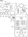
- FIG. 2 shows a second exemplary arrangement for the commissioning of a control and RSG2 device for field devices FG1 - FG8 for building automation, wherein between the Control unit RSG2 and a mobile communication terminal MG2 of a user B2 a communication connection (zV WLAN) can be set up; wherein the mobile communication terminal MG2 is set up to query data points DP of the regulation and control device RSG2 via the communication connection and to check their respective state, wherein a data point DP represents the state of a parameter of a field device FG1-FG8; and wherein the mobile communication terminal MG2 is further configured to transmit the state of the data points DP via a further communication connection C2 (eg cloud connection via WLAN or Internet) to a central location ZS2.
- a further communication connection C2 eg cloud connection via WLAN or Internet
- the operator can install a connection unit VG (eg WLAN stick) in the regulation and control unit RSG2 in order to establish a connection between the mobile communication terminal MG2 and the regulation and control unit RSG2 to install.
- a connection unit VG eg WLAN stick
- a cable connection between the mobile communication terminal MG2 and the control unit RSG2 can be used.
- the field devices FG1 - FG8 (eg thermostats, actuators, ventilators) should be controlled or controlled with the control unit RSG2.
- the field devices FG1 - FG8 are connected to the control device RSG2 via the following exemplary communication mechanisms: BACnet IP, Modbus RTU, or KNX PL-Link.
- the user B2 (eg commissioning) is equipped with a mobile communication terminal MG2 (eg smartphone, tablet computer). With the mobile communication terminal MG2, the user B2 can set up communication connections to the regulation and control device RSG2 and to a central location ZS2. The communication connections can be set up eg via WLAN or over the Internet. The communication connection to the central point ZS2 can be done eg via a server in a cloud C2.
- a mobile communication terminal MG2 eg smartphone, tablet computer.
- the communication connections can be set up eg via WLAN or over the Internet.
- the communication connection to the central point ZS2 can be done eg via a server in a cloud C2.
- the mobile communication terminal MG2 has a software program (e.g., App) for starting up and / or testing data points DP of the field devices FG1-FG8 connected to the control unit RSG2.
- the software program (e.g., app for startup and testing of the controller RSG2) may be e.g. be downloaded via an Internet download on the mobile communication terminal MG2.
- the start-up / test software required for a particular controller (control and regulating device) can also be used, for example. by scanning a QR code visibly attached to the controller to the mobile communication terminal MG2 (e.g., smartphone).
- Communication terminals MG2 are usually equipped with a scan program or easily retrofitted by a download (scan app).
- This software program offers e.g. an online view of the data points DP of the respective field devices FG1 - FG8 thereby the commissioning of the respective to be tested data points DP of a field device can be done very quickly and easily. In addition, a reliable and simple documentation of the commissioning or the test takes place.
- the online view of the data points DP is advantageously carried out via a corresponding visualization on the display D of the mobile communication terminal MG2.
- the states of the tested data points DP are forwarded from the mobile communication terminal MG2 to the central location ZS2. This can be done online or via a batch run.
- the data points DP relevant for a regulation and control device RSG2 are collected in a data container (eg list, array) and sent to the central point ZS2.
- this data can be further processed or evaluated, for example in a building management system, an engineering system, or a project management system.
- One aspect of the present invention is the linking of multimedia functions (navigation, camera, audio note and textual input) of a mobile communication terminal (e.g., smartphone, tablet computer) and the online view of the data points to be tested. This ensures the ease of commissioning of data points and devices, especially in the room with efficient documentation.
- the controllers In building automation, the controllers (control and regulating devices) are installed decentrally in the respective room in which the control and regulation is carried out. This requires that during commissioning, the controller must be located quickly to diagnose problems occurring during commissioning. Through a wireless sensor (e.g., beacon) connected to the controller, it can be quickly located by the appropriate software program (e.g., Mobile Commissioning App), thus minimizing the time consuming search for the controller. Thus, e.g. Subcontractors who do not have local knowledge of the installation of the controllers are also instructed to carry out the commissioning tests with a very short training effort.
- a wireless sensor e.g., beacon
- Mobile Commissioning App e.g., Mobile Commissioning App
- the test condition (not checked”, "faulty”, “successfully checked") can be very easily recorded.
- the collected data is e.g. sent by e-mail to the project manager for evaluation and further processing. This can easily provide an overview (and statistics based on these data) regarding progress and problems encountered.
- the project manager can easily understand the progress based on the data collected with the software program (Mobile Commissioning App) and can also present this to the client and initiate the targeted resolution of the problems.
- Each change of state is stored in the software program (Mobile Commissioning App) in the connection to the data point. These data are exported and further processed in the office (“Office Data processing”) and archived. This history of the data point is archived with all test conditions and can be used in later extensions or problem analysis.
- Mobile Commissioning App Mobile Commissioning App
- the location of the control and regulation device in a building is communicated to the mobile communication terminal by a corresponding position signal.
- the position signal is emitted by the control and control unit and received by the mobile communication terminal.
- the mobile communication terminal can, based on the received position signal, navigate the operator (eg, commissioning engineer) to the installation location of the control and regulation device, with appropriate navigation software.
- Mobile communication terminals eg smartphone, tablet computer
- Method and arrangement for the commissioning of a control and control device for field devices for a building automation wherein between the control and control device and a mobile communication terminal of a user, a communication connection is created; wherein the mobile communication terminal is adapted to query the communication connection data points of the control and control device and to check their respective state, wherein a data point represents the state of a parameter of a field device; and wherein the mobile communication terminal is further adapted to transmit the state of the data points via a further communication link to a central location.
Landscapes
- Physics & Mathematics (AREA)
- General Physics & Mathematics (AREA)
- Engineering & Computer Science (AREA)
- Automation & Control Theory (AREA)
- Telephonic Communication Services (AREA)
Abstract
Description
- Die Erfindung betrifft ein Verfahren und eine Anordnung zur Inbetriebnahme eines Regel- und Steuergerätes für Feldgeräte für eine Gebäudeautomatisierung.
- Die Inbetriebnahme von Regel- und Steuergeräten bei einer Gebäudeautomatisierung z.B. für Heizung-, Lüftung- oder Klimafunktionalität (HLK) wird heutzutage oft unzureichend dokumentiert. Insbesondere erfolgt bei der Inbetriebnahme dieser Geräte oft eine unzureichende bzw. lückenhafte Testdokumentation. Dadurch verzögert sich u.a. die Fehlerbehebung. Auch ist die Projektfortschrittsverfolgung bei der Inbetriebnahme von HLK-Produkten in Gebäuden oft intransparent für den verantwortlichen Projektleiter.
- Der Fortschritt der Inbetriebnahme wird heutzutage mit Hilfe eines Inbetriebnahmetools am Notebook oder mittels Datenpunktlisten auf Papier dokumentiert. Problembeschreibungen werden hauptsächlich als Text eingegeben, oft ist der eingegebene Text bruchstückhaft. Die Dokumentation der Inbetriebnahme erfolgt individuell und manuell vom jeweiligen Inbetriebnahmetechniker. Die Dokumentation ist somit zeitaufwendig und oft lückenhaft.
- Es ist daher die Aufgabe der vorliegenden Erfindung ein Verfahren und eine Anordnung zur Inbetriebnahme eines Regel- und Steuergerätes für Feldgeräte für eine Gebäudeautomatisierung bereitzustellen, wobei insbesondere eine effiziente und vollständige Dokumentation der Inbetriebnahme erfolgt.
- Die Aufgabe wird gelöst durch ein Verfahren zur Inbetriebnahme eines Regel- und Steuergerätes für Feldgeräte für eine Gebäudeautomatisierung, wobei zwischen dem Regel- und Steuergerät und einem mobilen Kommunikationsendgerät eines Benutzers eine Kommunikationsverbindung erstellt wird; wobei das mobile Kommunikationsendgerät dazu eingerichtet ist, über die Kommunikationsverbindung Datenpunkte des Regel- und Steuergerätes abzufragen und auf ihren jeweiligen Zustand zu überprüfen, wobei ein Datenpunkt den Zustand eines Parameters eines Feldgerätes repräsentiert; und wobei das mobile Kommunikationsendgerät weiter dazu eingerichtet ist, den jeweiligen Zustand der Datenpunkte über eine weitere Kommunikationsverbindung an eine zentrale Stelle zu übertragen. Mobile Kommunikationsendgeräte (z.B. Smartphones, Tablet-Computer) sind heutzutage weitverbreitet und mit leistungsfähigen Prozessoren und Speichern ausgestattet. Mit mobilen Kommunikationsendgeräten sind Kommunikationsverbindungen mit entsprechend ausgestatteten Regel- und Steuergeräten (z.B. Controller) oder mit zentralen Stellen (z.B. Leitstelle, Gebäudeleitstelle, Gebäudemanagementsystem, Server) leicht herstellbar, z.B. über WLAN oder Internet. Das mobile Kommunikationsendgerät ist über ein installiertes Softwareprogramm (z.B. App) dazu eingerichtet, über die Kommunikationsverbindung Datenpunkte des Regel- und Steuergerätes abzufragen und auf ihren jeweiligen Zustand zu überprüfen.
Die App (d.h. das Softwareprogramm) wird z.B. über eine URL vom Internet (Android: Play Store, iOS: AppStore) auf das mobile Kommunikationsendgerät installiert.
In der zentralen Stelle können die übertragenen Datenpunkte weiter analysiert werden, insbesondere kann der Projektfortschritt bei der Inbetriebnahme der Regel- und Steuergeräte protokolliert und nachvollzogen werden und der Fortschritt überprüft werden. - Ein Datenpunkt ist insbesondere eine Bezeichnung für eine Eingabe- oder Ausgabefunktion bestehend aus allen zugeordneten Informationen (welche den Aktualwert und/oder Zustand und Parameter (Eigenschaften und Attribute), z. B. Signalart und Signalkennlinie, Messbereich, Einheit und Zustandstexte umfassen), welche ihre Bedeutung (Semantik) vollständig beschreiben und die über eine Datenpunktadresse und/oder eine Benutzeradresse, identifiziert wird.
- Unter Inbetriebnahme wird insbesondere das Einstellen eines Systems, einer Anlage oder Maschine verstanden. D.h. insbesondere Maßnahmen und Handlungen (z. B. Konfiguration, Parametrierung, Optimierung und Test), die notwendig sind, um eine Maschine oder Anlage betriebsbereit bzw. einsatzbereit zu machen. Eine Inbetriebnahme umfasst Maßnahmen und Tätigkeiten, die nach der Montage der Hardware bzw. nach der Installation der Software zur Einrichtung und Prüfung des Produkts/Systems durchgeführt werden.
- Unter einem Feldgerät werden insbesondere Sensoren und Aktoren verstanden. Zustände der Feldgeräte werden im Regel und Steuergerät (z.B. Controller) auf entsprechende Datenpunkte abgebildet.
- Eine erste vorteilhafte Ausgestaltung der Erfindung liegt darin, dass der Verbauungsort des Regel- und Steuergerätes in einem Gebäude durch ein entsprechendes Positionssignal dem mobilen Kommunikationsendgerät mitgeteilt wird. Das Regel- und Steuergerät bzw. der Controller für die Steuerung von HLK- oder Raumautomatisierungsanwendungen ist dezentral in einem Raum montiert und oft schwer auffindbar, in der Regel in der Zwischendecke, unter einem Fensterpanel, oder im Zwischenboden). Das erschwert für den Inbetriebsetzer das Auffinden (Lokalisierung) des Regel- und Steuergerätes bzw. des Controllers. Durch das Positionssignal wird z.B. ein Inbetriebsetzer direkt zum Verbauungsort des Regel- und Steuergerätes in einem Raum geführt. Unnötige Zeit zum Suchen des Regel- und Steuergerätes entfällt. Das Positionssignal kann satellitenbasiert (z.B. über GPS) oder durch ein Indoor Positioning System (IPS, System zur Indoor-Positionsbestimmung) bereitgestellt werden. Das mobile Kommunikationsendgerät (z.B. Smartphone) kann den Benutzer zum entsprechenden Regel- und Steuergerät navigieren (z.B. durch Sprachausgabe).
- Eine weitere vorteilhafte Ausgestaltung der Erfindung liegt darin, dass das Positionssignal vom Regel- und Steuergerät ausgesendet wird. Das Positionssignal kann z.B. durch einen kleinen Sender (z.B. Beacon, iBeacon) ausgegeben werden, der sich im oder am Regel- und Steuergerät befindet. Mit Vorteil basiert der Sender auf Bluetooth Low Energy (BLE).
- Eine weitere vorteilhafte Ausgestaltung der Erfindung liegt darin, dass die Kommunikation zwischen dem Regel- und Steuergerät und dem mobilen Kommunikationsendgerät über eine drahtlose Verbindung (z.B. WLAN, NFC, Bluetooth) erfolgt. Üblicherweise sind in Gebäuden drahtlose Kommunikationsnetze schon installiert oder leicht nachrüstbar bzw. realisierbar. Mobile Kommunikationsendgeräte (z.B. Smartphones) sind für eine drahtlose Kommunikation üblicherweise mit entsprechender Hardware und Software ausgestattet.
- Eine weitere vorteilhafte Ausgestaltung der Erfindung liegt darin, dass die drahtlose Verbindung zwischen dem Regel- und Steuergerät und dem mobilen Kommunikationsendgerät über ein vom Benutzer am Regel- und Steuergerät installiertes Gerät (z.B. ein Funkmodul) erfolgt. Wenn ein Regel- und Steuergerät nicht mit einem Sender/Empfänger für eine drahtlose Verbindung ausgestattet ist, kann ein Benutzer (z.B. Inbetriebsetzer) am Regel- und Steuergerät ein Gerät (z.B. WLAN-Adapter) für eine drahtlose Kommunikation mit dem mobilen Kommunikationsendgerät installieren und dadurch eine Kommunikationsverbindung zwischen dem Regel- und Steuergerät (z.B. Controller) und dem mobilen Kommunikationsendgerät einrichten.
- Eine weitere vorteilhafte Ausgestaltung der Erfindung liegt darin, dass die an die zentrale Stelle gesendeten Zustände der Datenpunkte in ein Projektmanagementsystem (z.B. MS Project) übertragen werden. Dadurch kann der Projektfortschritt bei der Inbetriebnahme sehr leicht protokolliert und nachvollzogen werden.
- Eine weitere vorteilhafte Ausgestaltung der Erfindung liegt darin, dass die an die zentrale Stelle gesendeten Zustände der Datenpunkte in ein Gebäudemodell (BIM) für das entsprechende Gebäude übertragen werden. Bei der zentralen Stelle kann es sich z.B. um ein Gebäudeautomatisierungssystems bzw. Gebäudemanagementsystem handeln. Das Gebäudemodell (BIM, Building Information Model) des entsprechenden Gebäudes ist z.B. in einem Speicher (z.B. Flash-Speicher) des Gebäudeautomatisierungssystems abgelegt, bzw. in einer Datenbank auf die das Gebäudeautomatisierungssystem Zugriff hat. Durch die Übertragung der Zustände der Datenpunkte in ein Gebäudemodell wird die Konsistenz zwischen der im Gebäude installierten Geräte und dem elektronischen Gebäudemodell sichergestellt. Die Übertragung der Zustände der Datenpunkte in das Gebäudemodell kann online oder durch einen Batchlauf (z.B. abends oder zu festgelegten Zeitpunkten) erfolgen.
- Eine weitere vorteilhafte Ausgestaltung der Erfindung liegt darin, dass ein erkannter Fehlerzustand in einem Datenpunkt auf dem mobilen Kommunikationsendgerät angezeigt wird und wobei der erkannte Fehlerzustand vom Bediener mit weiteren Daten versehen, an die zentrale Stelle gesendet wird. Auf dem mobilen Kommunikationsendgerät des Bedieners ist eine Inbetriebnahme- und/oder Testsoftware für das in Betrieb zu nehmende Regel- und Steuergerät installiert (z.B. durch einen Internet-Download). Mit Hilfe dieser Software kann der Bediener mit dem mobilen Kommunikationsendgerät über die Kommunikationsverbindung Schritt für Schritt Testfälle auf dem Regel- und Steuergerät abarbeiten. Erkannte Fehler werden auf dem Display des Kommunikationsendgerätes angezeigt. Der Bediener kann eine Fehlermeldung bezüglich eines erkannten Fehlers vom Kommunikationsendgerät zur zentralen Stelle (z.B. Gebäudemanagementsystem, Leitstelle, Leitserver) senden und diese Fehlermeldung dediziert mit weiteren Daten zum Fehler versehen bzw. anreichern. Z.B. mit Daten zum Verbauungsort (z.B. Lage, Temperatur, Feuchtigkeit), Fotos von Gerät und/oder Verbauungsort, Einschätzung zur Fehlerursache und/oder Fehlerbehebung (Reparatur ausreichend oder Austausch erforderlich). Dadurch wird die Fehlerbeschreibung konkreter und umfassender. Die Analyse und Behebung der Fehlermeldung wird durch die anschauliche Dokumentation effektiver.
- Eine weitere vorteilhafte Ausgestaltung der Erfindung liegt darin, dass der an die zentrale Stelle übertragene Zustand der Datenpunkte weitere Informationen umfasst, insbesondere eine Audionotiz und/oder ein Foto des dazugehörigen Feldgerätes. Dadurch kann in der zentralen Stelle z.B. verifiziert werden, ob die Inbetriebnahme erfolgt ist.
- Eine weitere vorteilhafte Ausgestaltung der Erfindung liegt darin, dass durch die zentrale Stelle eine Auswertung der empfangenen Daten erfolgt und weitere Massnahmen eingeleitet werden. Die Auswertung bzw. Analyse der empfangenen StörMeldung kann in einem Server der zentralen Stelle (z.B. Gebäudeleitstelle) z.B. durch Mechanismen der künstlichen Intelligenz (KI) mit entsprechender Software erfolgen. Wenn z.B. als Massnahme eine Reparatur des Feldgerätes oder des Controllers erforderlich ist, kann einem erforderlichen Servicepersonal z.B. mitgeteilt werden, welche Ersatzteile mitzunehmen sind. Eine Auswertung der empfangenen Daten kann z.B. auf einer Foto- bzw. Bildanalyse beruhen, wenn die empfangenen Daten entsprechende Fotos umfassen.
- Eine weitere vorteilhafte Ausgestaltung der Erfindung liegt in einer Anordnung zur Inbetriebnahme eines Regel- und Steuergerätes für Feldgeräte für eine Gebäudeautomatisierung, wobei zwischen dem Regel- und Steuergerät und einem mobilen Kommunikationsendgerät eines Benutzers eine Kommunikationsverbindung eingerichtet wird; wobei das mobile Kommunikationsendgerät dazu eingerichtet ist, über die Kommunikationsverbindung Datenpunkte des Regel- und Steuergerätes abzufragen und auf ihren jeweiligen Zustand zu überprüfen, wobei ein Datenpunkt den Zustand eines Parameters eines Feldgerätes darstellt; wobei das mobile Kommunikationsendgerät weiter dazu eingerichtet ist, den Zustand der jeweiligen Datenpunkte über eine weitere Kommunikationsverbindung an eine zentrale Stelle zu übertragen. Die Anordnung ist mit handelsüblicher Hardware bzw. Software realisierbar.
- Eine weitere vorteilhafte Ausgestaltung der Erfindung liegt darin, dass die Anordnung ein Positionsbestimmungssystem (IPS) umfasst zur Bestimmung des Verbauungsortes des Regel- und Steuergerätes in einem Gebäude. Auch Positionsbestimmungssysteme (satellitengestützt (z.B. GPS) und/oder Indoor-Positionsbestimmungssysteme (IPS)) sind heutzutage weitverbreitet oder leicht nachrüstbar. Durch ein Positionsbestimmungssystem kann ein Benutzer (z.B. Inbetriebsetzter) direkt zum entsprechenden Regel- und Steuergerät mit seinem mobilen Kommunikationsendgerät geleitet werden. Mit Vorteil ist das Regel- und Steuergerät mit einem Sender (z.B. iBeacon) ausgestattet, der Positionsdaten des Gerätes (d.h. den Verbauungsort des Regel- und Steuergerätes) aussendet. Das mobile Kommunikationsendgerät empfängt diese Positionsdaten und navigiert den Benutzer zum Gerät. Dies erspart Kosten und Zeit und vereinfacht die Installation wesentlich.
- Durch die umfassende Dokumentation wird auch der Betrieb des Gebäudes wesentlich vereinfacht, Service Arbeiten werden durch das IPS (Indoor Positioning System) beschleunigt und ein allfälliger Austausch von Geräten im Service oder Fehlerfall wird durch die umfassende Dokumentation besser planbar.
- Die Erfindung sowie vorteilhafte Ausführungen der vorliegenden Erfindung werden am Beispiel der nachfolgenden Figuren erläutert. Dabei zeigen:
- FIG 1
- eine erste beispielhafte Anordnung zur Inbetrieb-nahme eines Regel- und Steuergerätes für Feldgeräte für eine Gebäudeautomatisierung,
- FIG 2
- eine zweite beispielhafte Anordnung zur Inbetriebnahme eines Regel- und Steuergerätes für Feldgeräte für eine Gebäudeautomatisierung,
- FIG 3
- beispielhafte Use Cases zur Inbetriebnahme eines Regel- und Steuergerätes für Feldgeräte durch ein entsprechend eingerichtetes mobiles Kommunikationsendgerät, und
- FIG 4
- ein beispielhaftes Flussdiagramm für ein Verfahren zur Inbetriebnahme eines Regel- und Steuergerätes für Feldgeräte für eine Gebäudeautomatisierung.
-
Figur 1 zeigt eine erste beispielhafte Anordnung zur Inbetriebnahme eines Regel- und Steuergerätes RSG1 für Feldgeräte FG für eine Gebäudeautomatisierung, wobei zwischen dem Regel- und Steuergerät RSG1 und einem mobilen Kommunikationsendgerät MG1 (z.B. Smartphone, Tablet-Computer) eines Benutzers B1 (z.B. Inbetriebsetzer) eine Kommunikationsverbindung KV1 einrichtbar ist; wobei das mobile Kommunikationsendgerät MG1 dazu eingerichtet ist über die Kommunikationsverbindung KV1 Datenpunkte DP des Regel- und Steuergerätes RSG1 abzufragen und auf ihren jeweiligen Zustand zu überprüfen, wobei ein Datenpunkt DP den Zustand eines Parameters eines Feldgerätes FG darstellt; und wobei das mobile Kommunikationsendgerät MG1 weiter dazu eingerichtet ist, den Zustand der Datenpunkte DP über eine weitere Kommunikationsverbindung KV2 an eine zentrale Stelle ZS zu übertragen. Mit Vorteil handelt es sich bei den Kommunikationsverbindungen KV1 und KV2 um drahtlose Verbindungen (z.B. Funkverbindungen, wie WLAN). Mit Vorteil handelt es sich bei der Kommunikationsverbindung KV1 um WLAN-, NFC- oder Bluetooth-Verbindungen. - Das Regel- und Steuergerät RSG1 ist üblicherweise dazu eingerichtet ein oder mehrere Feldgeräte FG für eine Komfortsteuerung (z.B. Heizen, Lüften, Klima (HLK)) in einem Gebäude zu steuern bzw. zu regeln. Das mobile Kommunikationsendgerät MG1 ist mit einem Softwareprogramm (z.B. App) ausgestattet, mit der der Bediener B1 Testfälle an das Regel- und Steuergerätes RSG1 senden kann und die durch einen jeweiligen Testfall betroffenen Datenpunkte im Regel- und Steuergerät RSG1 abfragen kann. Die Zustände der Datenpunkte können auf dem mobilen Kommunikationsendgerät MG1 dargestellt und abgespeichert werden. Über die Kommunikationsverbindung KV2 können die Zustände der Datenpunkte DP an eine zentrale Stelle ZS weitergeleitet werden. Dies kann online (in Echtzeit) oder in einem Batchbetrieb (d.h. zu definierten Zeitpunkten) erfolgen. Bei der zentralen Stelle ZS kann es sich z.B. um eine Gebäudeleitstelle oder ein Gebäudemanagementsystem mit einem entsprechenden Server handeln. Mit Vorteil werden die Zustände der Datenpunkte DP in der zentralen Stelle ZS in einer Datenbank DB gespeichert. In der zentralen Stelle ZS können die empfangenen Daten zur Fortschrittskontrolle bei der Inbetriebnahme eines Gebäudes verwendet werden. Die empfangenen Daten können in der zentralen Stelle ZS weiter analysiert und ausgewertet werden und z.B. für die Service- und Wartungsplanung im Gebäude GB verwendet werden.
- Mit Vorteil umfasst die Anordnung ein Positionsbestimmungssystem (IPS, SAT) zur Bestimmung des Verbauungsortes des Regel- und Steuergerätes RSG1 im Gebäude GB. Beim Positionsbestimmungssystem kann es sich um ein satellitengestütztes Positionsbestimmungssystem handeln, z.B. GPS und/oder um ein Indoor-Positionsbestimmungssystem (z.B. iBeacon von Apple). Mit Vorteil basiert das Indoor-Positionsbestimmungssystem auf Bluetooth Low Energy (BLE). Mit Vorteil ist das Regel- und Steuergerät RSG1 mit einem Funksender (z.B. iBeacon) ausgestattet, der die Positionsdaten POS des Regel- und Steuergerätes RSG1 aussendet. Die Positionsdaten werden vom mobilen Kommunikationsendgerät MG1 des Benutzers B1 empfangen. Basierend auf den empfangenen Positionsdaten POS navigiert das mobile Kommunikationsendgerät MG1 den Benutzer zum Regel- und Steuergerät RSG1. Regel- und Steuergeräte RSG1 sind in einem Gebäude GB oft in deiner Decke oder unter einem Fussboden verbaut. Die Navigation zum Regel- und Steuergerät RSG1 bedeutet u.a. Zeitersparnis für den Benutzer B1.
-
Figur 2 zeigt eine zweite beispielhafte Anordnung zur Inbetriebnahme eines Regel- und Steuergerätes RSG2 für Feldgeräte FG1 - FG8 für eine Gebäudeautomatisierung, wobei zwischen dem Regel- und Steuergerät RSG2 und einem mobilen Kommunikationsendgerät MG2 eines Benutzers B2 eine Kommunikationsverbindung (z.V. WLAN) einrichtbar ist; wobei das mobile Kommunikationsendgerät MG2 dazu eingerichtet ist über die Kommunikationsverbindung Datenpunkte DP des Regel- und Steuergerätes RSG2 abzufragen und auf ihren jeweiligen Zustand zu überprüfen, wobei ein Datenpunkt DP den Zustand eines Parameters eines Feldgerätes FG1 - FG8 darstellt; und wobei das mobile Kommunikationsendgerät MG2 weiter dazu eingerichtet ist, den Zustand der Datenpunkte DP über eine weitere Kommunikationsverbindung C2 (z.B. Cloud-Verbindung über WLAN bzw. Internet) an eine zentrale Stelle ZS2 zu übertragen. - Wenn das Regel- und Steuergerät RSG2 keine Kommunikationsverbindung zum mobilen Kommunikationsendgerät MG2 bereitstellt, kann der Bediener beim Regel- und Steuergerät RSG2 ein Verbindungsgerät VG (z.B. WLAN-Stick) installieren, um eine Verbindung zwischen dem mobilen Kommunikationsendgerät MG2 und dem Regel- und Steuergerät RSG2 zu installieren. Prinzipiell kann auch eine Kabelverbindung zwischen dem mobilen Kommunikationsendgerät MG2 und dem Regel- und Steuergerät RSG2 verwendet werden.
- In der Darstellung gemäss
Figur 2 sollen mit dem Regel- und Steuergerätes RSG2 die Feldgeräte FG1 - FG8 (z.B. Thermostate, Stellglieder, Ventilator) geregelt bzw. gesteuert werden. Die Feldgeräte FG1 - FG8 sind mit dem Regel- und Steuergerät RSG2 über folgende beispielhafte Kommunikationsmechanismen verbunden: BACnet IP, Modbus RTU, oder KNX PL-Link. - Der Benutzer B2 (z.B. Inbetriebsetzer) ist mit einem mobilen Kommunikationsendgerät MG2 (z.B. Smartphone, Tablet-Computer) ausgestattet. Mit dem mobilen Kommunikationsendgerät MG2 kann der Benutzer B2 Kommunikationsverbindungen zum Regel- und Steuergerätes RSG2 und zu einer zentralen Stelle ZS2 einrichten. Die Kommunikationsverbindungen können z.B. über WLAN oder über das Internet eingerichtet werden. Die Kommunikationsverbindung zur zentralen Stelle ZS2 kann z.B. über einen Server in einer Cloud C2 erfolgen.
- Das mobile Kommunikationsendgerät MG2 verfügt über ein Softwareprogramm (z.B. App), um Datenpunkte DP der Feldgeräte FG1 - FG8, die am Regel- und Steuergerät RSG2 angeschlossen sind, in Betrieb zu nehmen und/oder zu testen. Das Softwareprogramm (z.B. App zur Inbetriebnahme und Testen des Regel- und Steuergerätes RSG2) kann z.B. über einen Internet-Download auf das mobile Kommunikationsendgerät MG2 geladen werden. Die für einen jeweiligen Controller (Regel- und Steuergerät) benötigte Inbetriebnahme-/Testsoftware kann auch z.B. durch das Scannen eines am Controller sichtbar angebrachten QR Codes auf das mobile Kommunikationsendgerät MG2 (z.B. Smartphone) geladen werden. Kommunikationsendgeräte MG2 sind üblicherweise mit einem Scan-Programm ausgestattet bzw. durch einen Download leicht damit nachrüstbar (Scan-App).
- Dieses Softwareprogramm (Inbetriebnahme-/Testsoftware) bietet z.B. eine Online-Sicht auf die Datenpunkte DP der jeweiligen Feldgeräte FG1 - FG8 dadurch kann die Inbetriebnahme der jeweiligen zu testenden Datenpunkte DP eines Feldgerätes sehr schnell und einfach erfolgen. Ausserdem erfolgt eine zuverlässige und einfache Dokumentation der Inbetriebnahme bzw. des Tests. Die Online-Sicht auf die Datenpunkte DP erfolgt mit Vorteil über eine entsprechende Visualisierung auf dem Display D des mobilen Kommunikationsendgerätes MG2.
- Die Zustände der getesteten Datenpunkte DP werden vom mobilen Kommunikationsendgerät MG2 an die zentrale Stelle ZS2 weitergeleitet. Dies kann online oder über einen Batchlauf erfolgen. Mit Vorteil werden die für ein Regel- und Steuergerät RSG2 relevanten Datenpunkte DP in einem Datencontainer (z.B. Liste, Array) gesammelt und an die zentrale Stelle ZS2 gesendet. In der zentralen Stelle ZS2 können diese Daten weiterverarbeitet oder ausgewertet werden, z.B. in einem Gebäudemanagementsystem, einem Engineeringsystem, oder einem Projektmanagementsystem.
- Ein Aspekt der vorliegenden Erfindung liegt in der Verknüpfung von multimedialen Funktionen (Navigation, Kamera, Audio Notiz und textuelle Eingabe) eines mobilen Kommunikationsendgerätes (z.B. Smartphone, Tablet-Computer) und der Online-Sicht der Datenpunkte, die zu testen sind. Damit wird die Einfachheit der Inbetriebnahme von Datenpunkten und Geräten insbesondere im Raum mit effizienter Dokumentation sichergestellt.
- Bei der Gebäudeautomatisierung werden die Controller (Regel- und Steuergeräte) dezentral im jeweiligen Raum, in dem die Steuerung und Regelung durchgeführt wird, installiert. Dies bedingt, dass bei der Inbetriebnahme der Controller schnell lokalisiert werden muss, um auftretende Probleme bei der Inbetriebnahme zu diagnostizieren. Durch einen Funksensor (z.B. Beacon), der mit dem Controller verbunden ist, bzw. im Controller installiert ist, kann dieser mittels des entsprechenden Softwareprogramms (z.B. Mobile Commissioning App) schnell lokalisiert werden und somit wird zeitintensive Suche nach dem Controller auf ein Minimum reduziert. So können z.B. auch Subunternehmer, die über keine Ortskenntnisse der Installation der Controller verfügen, beauftragt werden, die Inbetriebnahmetests mit sehr kurzem Einschulungsaufwand durchzuführen.
- Durch die Unterstützung der multimedialen Möglichkeiten des mobilen Kommunikationsendgerätes (Foto- & Audio Funktion, Texteingabe, Auswahl des Testzustandes in der Commissioning App) in Verbindung mit der Online-Sicht der Datenpunkte im Softwareprogramms (Mobile Commissioning App) kann die Inbetriebnahme sehr einfach und schnell beim jeweiligen zu testenden Datenpunkt dokumentiert werden. Insbesondere das Foto dokumentiert sehr anschaulich Inbetriebnahmeprobleme beim verknüpften Datenpunkt. Somit wird eine einfache und schnelle Dokumentation mit allen möglichen Daten zu Details durch das Softwareprogramm (Mobile Commissioning App) erstellt. Die nachfolgende Behebung der Inbetriebnahmeprobleme kann somit zielgerichtet initiiert werden. Damit ergibt sich eine Effizienzsteigerung bei der Inbetriebnahme.
- Bei jedem Datenpunkt kann im Softwareprogramm (Mobile Commissioning App) der Testzustand ("nicht geprüft", "fehlerhaft", "erfolgreich geprüft") sehr einfach festgehalten werden. Nach dem Abschluss der Inbetriebnahmetests werden die gesammelten Daten z.B. per E-Mail an den Projektleiter zur Auswertung und weiteren Bearbeitung gesandt. Dieser kann sich einfach einen Überblick (und auf diesen Daten aufbauend Statistiken) bezüglich Fortschritt und auftretender Probleme verschaffen. Der Projektleiter kann den Fortschritt basierend auf den mit dem Softwareprogramm (Mobile Commissioning App) gesammelten Daten einfach nachvollziehen und kann dies auch gegenüber dem Auftraggeber darstellen und die zielgerichtete Behebung der Probleme veranlassen.
- Die Dokumentation von Zusatzaufwänden durch Probleme, die durch die Fotos, die dem Datenpunkt zugewiesen sind, ist zielgerichtet unterstützt und damit ist die Erstellung von Nachträgen deutlich vereinfacht. Durch den Vergleich der Inbetriebnahmezustände zu verschiedenen Zeitpunkten basierend auf der Erfassung der Daten vom Softwareprogramm (Mobile Commissioning App) kann der Fortschritt der Inbetriebnahme auch gegenüber dem Auftraggeber visualisiert werden. Auf dieser Daten Basis können Teilrechnungen für erfolgreich abgeschlossene Tätigkeiten dokumentiert und erstellt werden. Zusatzaufwände für die Ermittlung von Problemen bei der Inbetriebnahme können auf der Basis der gesammelten Daten vom Softwareprogramm (Mobile Commissioning App) gegenüber dem Auftraggeber veranschaulicht werden und die Abrechnung wird damit vereinfacht und deutlich besser nachvollziehbar. Weiters kann bei mangelnder Vorleistung von anderen Firmen ein Zeitverzug bzw. erhöhter Mehraufwand bei der Installation der Controller durch die umfassende elektronische Dokumentation einfach begründet werden.
- Jede Zustandsänderung wird im Softwareprogramm (Mobile Commissioning App) in der Verbindung zum Datenpunkt gespeichert. Diese Daten werden exportiert und im Büro weiter bearbeitet ("Office Data processing") und archiviert. Damit wird Geschichte des Datenpunkts mit allen Testzuständen archiviert und kann bei späteren Erweiterungen oder Problemanalysen herangezogen werden.
- Weitere Aspekte der Erfindung:
- Die Erfindung nutzt nun die multimedialen Möglichkeiten von einem mobilen Kommunikationsendgerät (z.B. Smartphone) in Verbindung mit den Online-Datenpunkten, die am mobilen Kommunikationsendgerät mit aktuellen Werten, Zuständen etc. angezeigt werden.
- Somit können Inbetriebnahmeprobleme einfach mit Foto, Audio-Aufnahme, Textnotizen, oder Zuordnung der Verantwortung zur Behebung versehen bzw. dokumentiert werden.
- Korrekt funktionierend Datenpunkte bzw. Geräte können übersichtlich als erfolgreich geprüft markiert werden.
- Alle beim Kunden erfassten Daten können in einem DatenContainer zusammengefasst werden und somit benutzerfreundlich an den Projektleiter übertragen werden.
- Der Projektleiter kann sich einfach eine Auswertung der erfolgreich getesteten Datenpunkte und Geräte erstellen und kann Fehler eindeutig durch Zustand im System, Foto, Audio Notiz und Text nachvollziehen und die Behebung zeitnah veranlassen.
- Durch Indoor Navigation kann der Controller (Regel- und Steuergerät), an dem die Datenpunkte zu testen sind, einfach mit dem mobilen Kommunikationsendgerät lokalisiert werden.
-
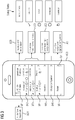
Figur 3 zeigt beispielhafte Use Cases (Anwendungsfälle) zur Inbetriebnahme eines Regel- und Steuergerätes (z.B. AS) für Feldgeräte durch ein entsprechend eingerichtetes mobiles Kommunikationsendgerät MG3. Auf dem mobilen Kommunikationsendgerät MG3 ist eine Software (z.B. App) zur Inbetriebnahme und zum Testen der Datenpunkte von durch das Regel- und Steuergerät gesteuerten Feldgeräte installiert. Mit Vorteil hat die Software eine grafische Bedienoberfläche, die über einen Touchscreen D2 (berührungssensitive Oberfläche) von einem Benutzer bedienbar ist. Die grafische Bedienoberfläche weist beispielhafterweise die Bedienfelder BF1 - BF7 auf: - BF1 ("AS State", d.h. Gerätezustand): zur Abfrage von Eigenschaften des Regel- und Steuergerätes bzw. Feldgerätes (z.B. Betriebsmodus (z.B. "operational" (aktiv), "idle" (inaktiv), "stopped" (beendet)) oder die jeweilige IP-Adresse.
- BF2 ("On board I/O", d.h. Ein-/Ausgabe): zur Anzeige bzw. Abfrage des aktuellen E/A-Zustandes (z.B. "operational" (aktiv), "idle" (inaktiv), "stopped" (beendet)).
- BF3 ("KNX PL-Link", d.h. KNX Verbindung): zur Anzeige bzw. Abfrage des Zustandes einer vorhandenen KNX Powerline Verbindung (z.B. "operational" (aktiv), "idle" (inaktiv), "stopped" (beendet)).
- BF4 ("Modbus", z.B. Kommunikation über Modbus RTU): zur Anzeige bzw. Abfrage des Zustandes einer vorhandenen Modbus Verbindung (z.B. "operational" (aktiv), "idle" (inaktiv), "stopped" (beendet)).
- BF5 ("Favorites", Favoriten): zur Anzeige bzw. Auswahl von wichtigen Datenpunkten / Sollwerten / Einstellwerten / Kenngrössen. Diese können bei Bedarf auch in Hierarchie gruppiert und zusammengefasst werden.
- BF6 ("Change Configuration", Änderung der Konfiguration): zur Änderung der Konfiguration.
- BF7 ("Restart", Restart einleiten): zum Einleiten eines Restarts des Softwareprogramms, z.B. für eine neue Testfallabarbeitung.
- In der Darstellung gemäss
Figur 3 sind folgende beispielhafte Use Cases (Anwendungsfälle) dargestellt: - Anwendungsfall UC0 (Properties of AS device object): Abfrage der Eigenschaften des Auutomatisierungsgerätes bzw. der Automationsstation (AS) oder Controllers für eine detaillierte Analyse geprüft werden.
- Anwendungsfall UC1 (Make Point test on buses): Test von Datenpunkten auf Bus (z.B. "On board I/O" - Test, "KNX PL-Link" - Test, "Modbus" - Test).
- Anwendungsfall UC2 (Commissioning - change setpoints): Inbetriebnahme - Sollwerte / Zeitverzögerungen / Grenzwerte ändern.
- Anwendungsfall UC3 (change plant / aggregate configuration): Ändern der Betriebsstättenkonfiguration bzw. der Aggregatskonfiguration.
- Anwendungsfall UC4 (Export data): Exportieren der Datenpunkte (an die zentrale Stelle). Alle Daten, die im Mobilgerät gesammelt wurden, können in einem komprimierten Daten Container an ein BIM übermittelt werden. Am rechten Rand in der Darstellung gemäss
Figur 4 ist in beispielhafter Weise der jeweilige Zustand (Status Testfall) eines Datenpunktes dargestellt:- "tested OK" (d.h. Testfall erfolgreich durchgeführt)
- "failed" (d.h. Testfall fehlerhaft durchgeführt)
- "not tested" (d.h. Datenpunkt nicht getestet)
- "overridden" (d.h. Datenpunkt ausser Kraft gesetzt).
- Die vorliegende Erfindung weist u.a. folgende vorteilhafte Merkmale auf:
- Online Kommunikation über BACnet IP zum Controller einer Plattform (IT Plattform) zur Gebäudeautomatisierung.
- Fotos beim Datenpunkt erstellen und an zentrale Stelle senden.
- Audio Notiz beim Datenpunkt erstellen und an zentrale Stelle senden.
- Export der Commissioning/Inbetriebnahme- Daten an zentrale Stelle.
- Indoor Navigation via Beacon (Leuchtfeuer das Positionsdaten aussendet) zum Regel- und Steuergerät (Controller).
- Auswertung der Commissioning/Inbetriebnahme- Daten kann über Tabellenkalkulationsprogramm (z.B. Excel) und/oder Projektmanagementtool (z.B. MS Project) gemacht werden.
- Automatische Fortschrittskontrolle bei Inbetriebnahmeprojekten.
- Unterstützung des Testprozesses (vor Ort) bei Inbetriebnahmeprojekten.
- Einfache Konfigurierung von Regel- und Steuergeräten vor Ort möglich.
- Die für einen jeweiligen Controller (Regel- und Steuergerät) benötigte Inbetriebnahme-Software kann z.B. durch das Scannen eines am Controller sichtbar angebrachten QR Codes auf das mobile Kommunikationsendgerät (z.B. Smartphone) geladen werden.
- Die Inbetriebnahme-Software (Commissioning App) auf dem mobilen Kommunikationsendgerät kann ein IP-Netzwerk nach angeschlossenen Feldgeräten (z.B. BACnet Geräte). Dadurch ist eine systematische und vollständige Inbetriebnahme der vorhandenen Feldgeräte gewährleistet. Zu testende Geräte und die zu testenden Datenpunkte können durch die Inbetriebnahme-Software von einem Inbetriebsetzer einfach ausgewählt werden.
- Daten eines zu testenden Gerätes können ausgewählt und auf dem Display des mobilen Kommunikationsendgerätes angezeigt werden
- Die Inbetriebnahme-Software (Commissioning App) ermöglicht ein einfaches Ändern von Sollwerten in den Feldgeräten bzw. im Controller.
- Die Konfiguration/Parametrierung in den Feldgeräten bzw. im Controller kann über einen file-download (z.B. eine erprobte und geprüfte Grundkonfiguration oder auch ein Backup von diesem Gerät) auf das Gerät erfolgen oder direkt am Controller online (d.h. der Benutzer kann die Grundkonfiguration des Controllers ohne zusätzliche Daten direkt und somit sehr effektiv ändern).
-
Figur 4 zeigt ein beispielhaftes Flussdiagramm für ein Verfahren zur Inbetriebnahme eines Regel- und Steuergerätes für Feldgeräte für eine Gebäudeautomatisierung, - (VS1) wobei zwischen dem Regel- und Steuergerät und einem mobilen Kommunikationsendgerät eines Benutzers eine Kommunikationsverbindung erstellt wird;
- (VS2) wobei das mobile Kommunikationsendgerät dazu eingerichtet ist, über die Kommunikationsverbindung Datenpunkte des Regel- und Steuergerätes abzufragen und auf ihren jeweiligen Zustand zu überprüfen, wobei ein Datenpunkt den Zustand eines Parameters eines Feldgerätes repräsentiert; und
- (VS3) wobei das mobile Kommunikationsendgerät weiter dazu eingerichtet ist, den jeweiligen Zustand der Datenpunkte über eine weitere Kommunikationsverbindung an eine zentrale Stelle (z.B. Gebäudeleitstelle, Projektserver, Gebäudemanagementsystem) zu übertragen (die Übertragung kann in Echtzeit, im Batch-Betrieb, oder parallel zur Abfrage und Überprüfung der jeweiligen Zustände der Datenpunkte erfolgen). Mobile Kommunikationsendgeräte (z.B. Smartphones, Tablet-Computer) sind heutzutage weitverbreitet und mit leistungsfähigen Prozessoren und Speichern ausgestattet. Durch das Installieren eines entsprechenden Programmes (z.B. durch Herunterladen einer App) wird das mobile Kommunikationsendgerät eingerichtet, das Verfahren auszuführen. Die Infrastruktur zur Durchführung des Verfahrens ist in Gebäuden üblicherweise vorhanden, bzw. durch handelsübliche Hardware leicht und schnell nachrüstbar.
- Mit Vorteil wird der Verbauungsort des Regel- und Steuergerätes in einem Gebäude durch ein entsprechendes Positionssignal dem mobilen Kommunikationsendgerät mitgeteilt wird. Mit Vorteil wird das Positionssignal vom Regel- und Steuergerät ausgesendet und vom mobilen Kommunikationsendgerät empfangen. Das mobile Kommunikationsendgerät kann, basierend auf dem empfangenen Positionssignal den Bediener (z.B. Inbetriebsetzer) zum Verbauungsort des Regel- und Steuergerätes navigieren, mit entsprechender Navigationssoftware. Mobile Kommunikationsendgeräte (z.B. Smartphone, Tablet-Computer) sind heutzutage üblicherweise mit entsprechender Navigationssoftware ausgestattet, bzw. sind sie durch einen entsprechenden Download aufrüstbar.
- Verfahren und Anordnung zur Inbetriebnahme eines Regel- und Steuergerätes für Feldgeräte für eine Gebäudeautomatisierung, wobei zwischen dem Regel- und Steuergerät und einem mobilen Kommunikationsendgerät eines Benutzers eine Kommunikationsverbindung erstellt wird; wobei das mobile Kommunikationsendgerät dazu eingerichtet ist über die Kommunikationsverbindung Datenpunkte des Regel- und Steuergerätes abzufragen und auf ihren jeweiligen Zustand zu überprüfen, wobei ein Datenpunkt den Zustand eines Parameters eines Feldgerätes repräsentiert; und wobei das mobile Kommunikationsendgerät weiter dazu eingerichtet ist, den Zustand der Datenpunkte über eine weitere Kommunikationsverbindung an eine zentrale Stelle zu übertragen.
-
- SAT, IPS
- Positionsbestimmungssystem
- POS
- Positionsdaten
- B1, B2
- Benutzer
- MG1 - MG3
- Mobiles Gerät
- D1, D2
- Display
- ZS1, ZS2
- Zentrale Stelle
- GMS
- Gebäudemanagementsystem
- C1, C2
- Cloud
- PL
- Projektleiter
- DB
- Datenbank
- GB
- Gebäude
- KV1 - KV5
- Kommunikationsverbindung
- TF
- Testfall
- DP
- Datenpunkt
- RSG1, RSG2
- Regel- und Steuergerät
- VG
- Verbindungsgerät
- UC0 - UC4
- Use Case
- FG, FG1 - FG8
- Feldgerät
- BF1 - BF7
- Bedienfelder
- VS1 - VS3
- Verfahrensschritt
Claims (12)
- Verfahren zur Inbetriebnahme eines Regel- und Steuergerätes (RSG1, RSG2) für Feldgeräte (FG, FG1 - FG8) für eine Gebäudeautomatisierung,(VS1) wobei zwischen dem Regel- und Steuergerät (RSG1, RSG2) und einem mobilen Kommunikationsendgerät (MG1 - MG3) eines Benutzers (B1, B2) eine Kommunikationsverbindung (KV1) erstellt wird;(VS2) wobei das mobile Kommunikationsendgerät (MG1 - MG3) dazu eingerichtet, ist über die Kommunikationsverbindung (KV1) Datenpunkte (DP) des Regel- und Steuergerätes (RSG1, RSG2) abzufragen und auf ihren jeweiligen Zustand zu überprüfen, wobei ein Datenpunkt (DP) den Zustand eines Parameters eines Feldgerätes (FG, FG1 - FG8) repräsentiert; und(VS3) wobei das mobile Kommunikationsendgerät (MG1 - MG3) weiter dazu eingerichtet ist, den jeweiligen Zustand der Datenpunkte (DP) über eine weitere Kommunikationsverbindung (KV2) an eine zentrale Stelle (ZS1, ZS2) zu übertragen.
- Verfahren nach Anspruch 1, wobei der Verbauungsort des Regel- und Steuergerätes (RSG1, RSG2) in einem Gebäude durch ein entsprechendes Positionssignal (POS) dem mobilen Kommunikationsendgerät (MG1 - MG3) mitgeteilt wird.
- Verfahren nach Anspruch 2, wobei das Positionssignal (POS) vom Regel- und Steuergerät (RSG1, RSG2) ausgesendet wird.
- Verfahren nach einem der vorstehenden Ansprüche, wobei die Kommunikation zwischen dem Regel- und Steuergerät (RSG1, RSG2) und dem mobilen Kommunikationsendgerät (MG1 - MG3) über eine drahtlose Verbindung (KV1) erfolgt.
- Verfahren nach Anspruch 4, wobei die drahtlose Verbindung (KV1) zwischen dem Regel- und Steuergerät (RSG1, RSG2) und dem mobilen Kommunikationsendgerät (MG1 - MG3) über ein vom Benutzer (B1, B2) am Regel- und Steuergerät (RSG1, RSG2) installiertes Gerät (VG) erfolgt.
- Verfahren nach einem der vorstehenden Ansprüche, wobei die an die zentrale Stelle (ZS1, ZS2) gesendeten Zustände der Datenpunkte (DP) in ein Projektmanagementsystem übertragen werden.
- Verfahren nach einem der vorstehenden Ansprüche, wobei die an die zentrale Stelle (ZS1, ZS2) gesendeten jeweiligen Zustände der Datenpunkte (DP) in ein Gebäudemodell (BIM) für das entsprechende Gebäude (GB) übertragen werden.
- Verfahren nach einem der vorstehenden Ansprüche, wobei ein erkannter Fehlerzustand in einem Datenpunkt (DP) auf dem mobilen Kommunikationsendgerät (MG1 - MG3) angezeigt wird und wobei der erkannte Fehlerzustand vom Bediener (B1, B2) mit weiteren Daten versehen, an die zentrale Stelle (ZS1, ZS2) gesendet wird.
- Verfahren nach einem der vorstehenden Ansprüche, wobei der an die zentrale Stelle (ZS1, ZS2) übertragene Zustand der Datenpunkte (DP) weitere Informationen umfasst, insbesondere eine Audionotiz und/oder ein Foto des dazugehörigen Feldgerätes (FG, FG1 - FG8).
- Verfahren nach einem der vorstehenden Ansprüche, wobei durch die zentrale Stelle (ZS1, ZS2) eine Auswertung der empfangenen Daten erfolgt und weitere Massnahmen eingeleitet werden.
- Anordnung zur Inbetriebnahme eines Regel- und Steuergerätes (RSG1, RSG2) für Feldgeräte (FG, FG1 - FG8) für eine Gebäudeautomatisierung,
wobei zwischen dem Regel- und Steuergerät (RSG1, RSG2) und einem mobilen Kommunikationsendgerät (MG1 - MG3) eines Benutzers (B1, B2) eine Kommunikationsverbindung (KV1) eingerichtet wird;
wobei das mobile Kommunikationsendgerät (MG1 - MG3) dazu eingerichtet ist, über die Kommunikationsverbindung (KV1) Datenpunkte (DP) des Regel- und Steuergerätes (RSG1, RSG2) abzufragen und auf ihren jeweiligen Zustand zu überprüfen, wobei ein Datenpunkt (DP) den Zustand eines Parameters eines Feldgerätes (FG, FG1 - FG8) darstellt; und
wobei das mobile Kommunikationsendgerät (MG1 - MG3) weiter dazu eingerichtet ist, den Zustand der jeweiligen Datenpunkte (DP) über eine weitere Kommunikationsverbindung (KV2) an eine zentrale Stelle (ZS1, ZS2) zu übertragen. - Anordnung nach Anspruch 11, weiter umfassend ein Positionsbestimmungssystem (IPS) zur Bestimmung des Verbauungsortes des Regel- und Steuergerätes (RSG1, RSG2) in einem Gebäude (GB).
Applications Claiming Priority (1)
| Application Number | Priority Date | Filing Date | Title |
|---|---|---|---|
| DE102016216921.1A DE102016216921A1 (de) | 2016-09-07 | 2016-09-07 | Verfahren und Anordnung zur Inbetriebnahme von Regel- und Steuergeräten für eine Gebäudeautomatisierung |
Publications (2)
| Publication Number | Publication Date |
|---|---|
| EP3296826A1 true EP3296826A1 (de) | 2018-03-21 |
| EP3296826B1 EP3296826B1 (de) | 2021-04-07 |
Family
ID=59799279
Family Applications (1)
| Application Number | Title | Priority Date | Filing Date |
|---|---|---|---|
| EP17189461.1A Active EP3296826B1 (de) | 2016-09-07 | 2017-09-05 | Verfahren und anordnung zur inbetriebnahme von regel- und steuergeräten für eine gebäudeautomatisierung |
Country Status (2)
| Country | Link |
|---|---|
| EP (1) | EP3296826B1 (de) |
| DE (1) | DE102016216921A1 (de) |
Cited By (2)
| Publication number | Priority date | Publication date | Assignee | Title |
|---|---|---|---|---|
| EP3379803A1 (de) * | 2017-03-22 | 2018-09-26 | Frankl & Kirchner GmbH & Co KG Fabrik für Elektromotoren u. elektrische Apparate | Verfahren zur übertragung von daten zwischen einer maschinensteuerung und einem externen computer |
| EP4260147A1 (de) * | 2020-12-10 | 2023-10-18 | Endress+Hauser Process Solutions AG | Verfahren zum durchführen von bedienaktionen an einem feldgerät der automatisierungstechnik mittels einer bedieneinheit |
Families Citing this family (3)
| Publication number | Priority date | Publication date | Assignee | Title |
|---|---|---|---|---|
| DE102018214930A1 (de) | 2018-09-03 | 2020-03-05 | Siemens Schweiz Ag | Identifizieren von Steuergeräten in Automatisierungssystemen |
| DE102019217772A1 (de) | 2019-11-19 | 2021-05-20 | Siemens Schweiz Ag | Fernaktivierung der Wireless-Service-Schnittstelle eines Steuergerätes durch ein Peripheriegerät |
| DE102019217771A1 (de) * | 2019-11-19 | 2021-05-20 | Siemens Schweiz Ag | Fernaktivierung der Wireless-Service-Schnittstelle eines Steuergerätes über eine Funkschnittstelle |
Citations (2)
| Publication number | Priority date | Publication date | Assignee | Title |
|---|---|---|---|---|
| US20130054033A1 (en) * | 2011-08-25 | 2013-02-28 | Siemens Industry, Inc. | Synergistic interface system for a building network |
| US20140172121A1 (en) * | 2012-12-19 | 2014-06-19 | General Equipment And Manufacturing Company, Inc., D/B/A Topworx, Inc. | System and method for configuring a field device of a control system |
Family Cites Families (4)
| Publication number | Priority date | Publication date | Assignee | Title |
|---|---|---|---|---|
| US8160574B1 (en) | 2005-06-17 | 2012-04-17 | Fisher-Rosemount Systems, Inc. | Wireless architecture utilizing geo-referencing |
| DE102007041240A1 (de) | 2007-08-30 | 2009-03-05 | Endress + Hauser Process Solutions Ag | Verfahren zum Verbessern einer Diagnosefunktion eines Feldgerätes |
| DE102009021783A1 (de) | 2009-03-27 | 2010-09-30 | Hochschule Bochum | Lokalisierungssystem und Verfahren zur Lokalisierung wenigstens eines mobilen Telekommunikationsgeräts mittels Kurzstreckenfunk, insbesondere Bluetooth |
| DE102014112611A1 (de) | 2014-09-02 | 2016-03-03 | Endress + Hauser Conducta Gesellschaft für Mess- und Regeltechnik mbH + Co. KG | Verfahren zur Authentifikation mindestens einer ersten Einheit an mindestens einer zweiten Einheit |
-
2016
- 2016-09-07 DE DE102016216921.1A patent/DE102016216921A1/de not_active Withdrawn
-
2017
- 2017-09-05 EP EP17189461.1A patent/EP3296826B1/de active Active
Patent Citations (2)
| Publication number | Priority date | Publication date | Assignee | Title |
|---|---|---|---|---|
| US20130054033A1 (en) * | 2011-08-25 | 2013-02-28 | Siemens Industry, Inc. | Synergistic interface system for a building network |
| US20140172121A1 (en) * | 2012-12-19 | 2014-06-19 | General Equipment And Manufacturing Company, Inc., D/B/A Topworx, Inc. | System and method for configuring a field device of a control system |
Cited By (4)
| Publication number | Priority date | Publication date | Assignee | Title |
|---|---|---|---|---|
| EP3379803A1 (de) * | 2017-03-22 | 2018-09-26 | Frankl & Kirchner GmbH & Co KG Fabrik für Elektromotoren u. elektrische Apparate | Verfahren zur übertragung von daten zwischen einer maschinensteuerung und einem externen computer |
| EP4260147A1 (de) * | 2020-12-10 | 2023-10-18 | Endress+Hauser Process Solutions AG | Verfahren zum durchführen von bedienaktionen an einem feldgerät der automatisierungstechnik mittels einer bedieneinheit |
| EP4260147B1 (de) * | 2020-12-10 | 2026-03-25 | Endress+Hauser Process Solutions AG | Verfahren zum durchführen von bedienaktionen an einem feldgerät der automatisierungstechnik mittels einer bedieneinheit |
| US12625482B2 (en) | 2020-12-10 | 2026-05-12 | Endress+Hauser Process Solutions Ag | Method for performing operator control actions on an automation field device by means of an operator control unit |
Also Published As
| Publication number | Publication date |
|---|---|
| DE102016216921A1 (de) | 2018-03-08 |
| EP3296826B1 (de) | 2021-04-07 |
Similar Documents
| Publication | Publication Date | Title |
|---|---|---|
| EP3467597B1 (de) | Verfahren und system zur inbetriebnahme und/oder wartung eines regel- und steuergerätes für feldgeräte für eine gebäudeautomatisierung | |
| EP3296826B1 (de) | Verfahren und anordnung zur inbetriebnahme von regel- und steuergeräten für eine gebäudeautomatisierung | |
| DE102018124411A1 (de) | I/o-virtualisierung für die inbetriebnahme | |
| EP4235322B1 (de) | Steuervorrichtung, komponenten und mobile servicevorrichtung für eine hvac-anlage | |
| EP3070556B1 (de) | Verfahren, recheneinrichtung, benutzer-einheit und system zum parametrieren eines elektrischen gerätes | |
| DE112016004666T5 (de) | Automatische verteilung von vorrichtungsparametern zur inbetriebnahme von teilen eines getrennten prozessregelkreises | |
| EP3206174A1 (de) | Verfahren und anordnung zur inbetriebnahme eines gebäudeautomatisierungssystems | |
| DE102014103185A1 (de) | Hintergrunderhebung von Diagnosedaten aus messtechnischen Feldgeräten | |
| EP2821947A1 (de) | Verfahren und System zur Unterstützung von technischen Aufgaben in verteilten Steuersystemen | |
| EP2936258A1 (de) | System und verfahren zum einsatz in der automatisierungstechnik | |
| EP2019347A1 (de) | Verfahren zum Austausch von instandhaltungsrelevanten Informationen mit einem computerunterstützten Instandhaltungssystem | |
| DE102007039531A1 (de) | Verfahren zum Beschaffen von instandhaltungsrelevanten Informationen zu einer Anlage | |
| DE102020116200A1 (de) | Verbessertes arbeitsauftrags-generierungs- und -verfolgungssystem | |
| DE102018117573A1 (de) | Generische verschattung in industriellen prozessanlagen | |
| EP4345556B1 (de) | Verfahren für eine computer-gestützte installation von räumlich dezentral angeordneten komponenten einer maschine | |
| DE102013113037A1 (de) | Verfahren zum Bedienen eines Feldgerätes | |
| DE102019117196A1 (de) | Verfahren und vorrichtungen zum konfigurieren von zugriff auf signale von mehrvariablen-feldgeräten | |
| DE102018124251A1 (de) | Technologie zur bewertung und präsentation von informationen zur inbetriebnahme von feldvorrichtungen in verbindung mit einer prozessanlage | |
| DE102018115681A1 (de) | Verriegelungsketten-Visualisierung | |
| EP2399176A1 (de) | Verfahren und system zum engineering einer automatisierung zumindest eines teils einer technischen anlage | |
| EP4133468A1 (de) | Verfahren zum anbinden eines feldgeräts an eine cloud | |
| DE102004051834B4 (de) | Prüfgerät und Prüfverfahren für programmierbare Elektroinstallationen, sowie entsprechendes Computerprogramm und entsprechendes computerlesbares Speichermedium | |
| WO2024068952A1 (de) | Verfahren für eine computer-gestützte erstellung einer dezentralen, elektrischen topologie für eine maschine | |
| EP4584650A1 (de) | Verfahren für eine computer-gestützte installation von räumlich dezentral angeordneten komponenten einer maschine | |
| WO2024068899A1 (de) | Verfahren zur computer-gestützten bereitstellung einer anpassungsspezifikation für eine elektrotechnische installationstechnik |
Legal Events
| Date | Code | Title | Description |
|---|---|---|---|
| PUAI | Public reference made under article 153(3) epc to a published international application that has entered the european phase |
Free format text: ORIGINAL CODE: 0009012 |
|
| STAA | Information on the status of an ep patent application or granted ep patent |
Free format text: STATUS: THE APPLICATION HAS BEEN PUBLISHED |
|
| AK | Designated contracting states |
Kind code of ref document: A1 Designated state(s): AL AT BE BG CH CY CZ DE DK EE ES FI FR GB GR HR HU IE IS IT LI LT LU LV MC MK MT NL NO PL PT RO RS SE SI SK SM TR |
|
| AX | Request for extension of the european patent |
Extension state: BA ME |
|
| STAA | Information on the status of an ep patent application or granted ep patent |
Free format text: STATUS: REQUEST FOR EXAMINATION WAS MADE |
|
| 17P | Request for examination filed |
Effective date: 20180918 |
|
| RBV | Designated contracting states (corrected) |
Designated state(s): AL AT BE BG CH CY CZ DE DK EE ES FI FR GB GR HR HU IE IS IT LI LT LU LV MC MK MT NL NO PL PT RO RS SE SI SK SM TR |
|
| GRAP | Despatch of communication of intention to grant a patent |
Free format text: ORIGINAL CODE: EPIDOSNIGR1 |
|
| STAA | Information on the status of an ep patent application or granted ep patent |
Free format text: STATUS: GRANT OF PATENT IS INTENDED |
|
| INTG | Intention to grant announced |
Effective date: 20201221 |
|
| GRAS | Grant fee paid |
Free format text: ORIGINAL CODE: EPIDOSNIGR3 |
|
| GRAA | (expected) grant |
Free format text: ORIGINAL CODE: 0009210 |
|
| STAA | Information on the status of an ep patent application or granted ep patent |
Free format text: STATUS: THE PATENT HAS BEEN GRANTED |
|
| AK | Designated contracting states |
Kind code of ref document: B1 Designated state(s): AL AT BE BG CH CY CZ DE DK EE ES FI FR GB GR HR HU IE IS IT LI LT LU LV MC MK MT NL NO PL PT RO RS SE SI SK SM TR |
|
| REG | Reference to a national code |
Ref country code: GB Ref legal event code: FG4D Free format text: NOT ENGLISH |
|
| REG | Reference to a national code |
Ref country code: AT Ref legal event code: REF Ref document number: 1380503 Country of ref document: AT Kind code of ref document: T Effective date: 20210415 Ref country code: CH Ref legal event code: EP |
|
| REG | Reference to a national code |
Ref country code: DE Ref legal event code: R096 Ref document number: 502017009964 Country of ref document: DE |
|
| REG | Reference to a national code |
Ref country code: IE Ref legal event code: FG4D Free format text: LANGUAGE OF EP DOCUMENT: GERMAN |
|
| REG | Reference to a national code |
Ref country code: SE Ref legal event code: TRGR |
|
| REG | Reference to a national code |
Ref country code: LT Ref legal event code: MG9D |
|
| REG | Reference to a national code |
Ref country code: NL Ref legal event code: MP Effective date: 20210407 |
|
| PG25 | Lapsed in a contracting state [announced via postgrant information from national office to epo] |
Ref country code: LT Free format text: LAPSE BECAUSE OF FAILURE TO SUBMIT A TRANSLATION OF THE DESCRIPTION OR TO PAY THE FEE WITHIN THE PRESCRIBED TIME-LIMIT Effective date: 20210407 Ref country code: FI Free format text: LAPSE BECAUSE OF FAILURE TO SUBMIT A TRANSLATION OF THE DESCRIPTION OR TO PAY THE FEE WITHIN THE PRESCRIBED TIME-LIMIT Effective date: 20210407 Ref country code: NL Free format text: LAPSE BECAUSE OF FAILURE TO SUBMIT A TRANSLATION OF THE DESCRIPTION OR TO PAY THE FEE WITHIN THE PRESCRIBED TIME-LIMIT Effective date: 20210407 Ref country code: HR Free format text: LAPSE BECAUSE OF FAILURE TO SUBMIT A TRANSLATION OF THE DESCRIPTION OR TO PAY THE FEE WITHIN THE PRESCRIBED TIME-LIMIT Effective date: 20210407 Ref country code: BG Free format text: LAPSE BECAUSE OF FAILURE TO SUBMIT A TRANSLATION OF THE DESCRIPTION OR TO PAY THE FEE WITHIN THE PRESCRIBED TIME-LIMIT Effective date: 20210707 |
|
| PG25 | Lapsed in a contracting state [announced via postgrant information from national office to epo] |
Ref country code: LV Free format text: LAPSE BECAUSE OF FAILURE TO SUBMIT A TRANSLATION OF THE DESCRIPTION OR TO PAY THE FEE WITHIN THE PRESCRIBED TIME-LIMIT Effective date: 20210407 Ref country code: GR Free format text: LAPSE BECAUSE OF FAILURE TO SUBMIT A TRANSLATION OF THE DESCRIPTION OR TO PAY THE FEE WITHIN THE PRESCRIBED TIME-LIMIT Effective date: 20210708 Ref country code: IS Free format text: LAPSE BECAUSE OF FAILURE TO SUBMIT A TRANSLATION OF THE DESCRIPTION OR TO PAY THE FEE WITHIN THE PRESCRIBED TIME-LIMIT Effective date: 20210807 Ref country code: PT Free format text: LAPSE BECAUSE OF FAILURE TO SUBMIT A TRANSLATION OF THE DESCRIPTION OR TO PAY THE FEE WITHIN THE PRESCRIBED TIME-LIMIT Effective date: 20210809 Ref country code: PL Free format text: LAPSE BECAUSE OF FAILURE TO SUBMIT A TRANSLATION OF THE DESCRIPTION OR TO PAY THE FEE WITHIN THE PRESCRIBED TIME-LIMIT Effective date: 20210407 Ref country code: NO Free format text: LAPSE BECAUSE OF FAILURE TO SUBMIT A TRANSLATION OF THE DESCRIPTION OR TO PAY THE FEE WITHIN THE PRESCRIBED TIME-LIMIT Effective date: 20210707 Ref country code: RS Free format text: LAPSE BECAUSE OF FAILURE TO SUBMIT A TRANSLATION OF THE DESCRIPTION OR TO PAY THE FEE WITHIN THE PRESCRIBED TIME-LIMIT Effective date: 20210407 |
|
| REG | Reference to a national code |
Ref country code: DE Ref legal event code: R097 Ref document number: 502017009964 Country of ref document: DE |
|
| PG25 | Lapsed in a contracting state [announced via postgrant information from national office to epo] |
Ref country code: SM Free format text: LAPSE BECAUSE OF FAILURE TO SUBMIT A TRANSLATION OF THE DESCRIPTION OR TO PAY THE FEE WITHIN THE PRESCRIBED TIME-LIMIT Effective date: 20210407 Ref country code: SK Free format text: LAPSE BECAUSE OF FAILURE TO SUBMIT A TRANSLATION OF THE DESCRIPTION OR TO PAY THE FEE WITHIN THE PRESCRIBED TIME-LIMIT Effective date: 20210407 Ref country code: CZ Free format text: LAPSE BECAUSE OF FAILURE TO SUBMIT A TRANSLATION OF THE DESCRIPTION OR TO PAY THE FEE WITHIN THE PRESCRIBED TIME-LIMIT Effective date: 20210407 Ref country code: DK Free format text: LAPSE BECAUSE OF FAILURE TO SUBMIT A TRANSLATION OF THE DESCRIPTION OR TO PAY THE FEE WITHIN THE PRESCRIBED TIME-LIMIT Effective date: 20210407 Ref country code: EE Free format text: LAPSE BECAUSE OF FAILURE TO SUBMIT A TRANSLATION OF THE DESCRIPTION OR TO PAY THE FEE WITHIN THE PRESCRIBED TIME-LIMIT Effective date: 20210407 Ref country code: ES Free format text: LAPSE BECAUSE OF FAILURE TO SUBMIT A TRANSLATION OF THE DESCRIPTION OR TO PAY THE FEE WITHIN THE PRESCRIBED TIME-LIMIT Effective date: 20210407 Ref country code: RO Free format text: LAPSE BECAUSE OF FAILURE TO SUBMIT A TRANSLATION OF THE DESCRIPTION OR TO PAY THE FEE WITHIN THE PRESCRIBED TIME-LIMIT Effective date: 20210407 |
|
| PLBE | No opposition filed within time limit |
Free format text: ORIGINAL CODE: 0009261 |
|
| STAA | Information on the status of an ep patent application or granted ep patent |
Free format text: STATUS: NO OPPOSITION FILED WITHIN TIME LIMIT |
|
| 26N | No opposition filed |
Effective date: 20220110 |
|
| REG | Reference to a national code |
Ref country code: BE Ref legal event code: MM Effective date: 20210930 |
|
| GBPC | Gb: european patent ceased through non-payment of renewal fee |
Effective date: 20210905 |
|
| PG25 | Lapsed in a contracting state [announced via postgrant information from national office to epo] |
Ref country code: IS Free format text: LAPSE BECAUSE OF FAILURE TO SUBMIT A TRANSLATION OF THE DESCRIPTION OR TO PAY THE FEE WITHIN THE PRESCRIBED TIME-LIMIT Effective date: 20210807 Ref country code: MC Free format text: LAPSE BECAUSE OF FAILURE TO SUBMIT A TRANSLATION OF THE DESCRIPTION OR TO PAY THE FEE WITHIN THE PRESCRIBED TIME-LIMIT Effective date: 20210407 Ref country code: AL Free format text: LAPSE BECAUSE OF FAILURE TO SUBMIT A TRANSLATION OF THE DESCRIPTION OR TO PAY THE FEE WITHIN THE PRESCRIBED TIME-LIMIT Effective date: 20210407 |
|
| PG25 | Lapsed in a contracting state [announced via postgrant information from national office to epo] |
Ref country code: LU Free format text: LAPSE BECAUSE OF NON-PAYMENT OF DUE FEES Effective date: 20210905 Ref country code: IT Free format text: LAPSE BECAUSE OF FAILURE TO SUBMIT A TRANSLATION OF THE DESCRIPTION OR TO PAY THE FEE WITHIN THE PRESCRIBED TIME-LIMIT Effective date: 20210407 Ref country code: IE Free format text: LAPSE BECAUSE OF NON-PAYMENT OF DUE FEES Effective date: 20210905 Ref country code: GB Free format text: LAPSE BECAUSE OF NON-PAYMENT OF DUE FEES Effective date: 20210905 Ref country code: BE Free format text: LAPSE BECAUSE OF NON-PAYMENT OF DUE FEES Effective date: 20210930 |
|
| PG25 | Lapsed in a contracting state [announced via postgrant information from national office to epo] |
Ref country code: HU Free format text: LAPSE BECAUSE OF FAILURE TO SUBMIT A TRANSLATION OF THE DESCRIPTION OR TO PAY THE FEE WITHIN THE PRESCRIBED TIME-LIMIT; INVALID AB INITIO Effective date: 20170905 |
|
| PG25 | Lapsed in a contracting state [announced via postgrant information from national office to epo] |
Ref country code: CY Free format text: LAPSE BECAUSE OF FAILURE TO SUBMIT A TRANSLATION OF THE DESCRIPTION OR TO PAY THE FEE WITHIN THE PRESCRIBED TIME-LIMIT Effective date: 20210407 |
|
| PG25 | Lapsed in a contracting state [announced via postgrant information from national office to epo] |
Ref country code: MK Free format text: LAPSE BECAUSE OF FAILURE TO SUBMIT A TRANSLATION OF THE DESCRIPTION OR TO PAY THE FEE WITHIN THE PRESCRIBED TIME-LIMIT Effective date: 20210407 |
|
| PG25 | Lapsed in a contracting state [announced via postgrant information from national office to epo] |
Ref country code: MT Free format text: LAPSE BECAUSE OF FAILURE TO SUBMIT A TRANSLATION OF THE DESCRIPTION OR TO PAY THE FEE WITHIN THE PRESCRIBED TIME-LIMIT Effective date: 20210407 |
|
| PGFP | Annual fee paid to national office [announced via postgrant information from national office to epo] |
Ref country code: AT Payment date: 20250818 Year of fee payment: 9 Ref country code: FR Payment date: 20250915 Year of fee payment: 9 |
|
| PGFP | Annual fee paid to national office [announced via postgrant information from national office to epo] |
Ref country code: SE Payment date: 20250904 Year of fee payment: 9 |
|
| REG | Reference to a national code |
Ref country code: CH Ref legal event code: U11 Free format text: ST27 STATUS EVENT CODE: U-0-0-U10-U11 (AS PROVIDED BY THE NATIONAL OFFICE) Effective date: 20251210 |
|
| PG25 | Lapsed in a contracting state [announced via postgrant information from national office to epo] |
Ref country code: TR Free format text: LAPSE BECAUSE OF FAILURE TO SUBMIT A TRANSLATION OF THE DESCRIPTION OR TO PAY THE FEE WITHIN THE PRESCRIBED TIME-LIMIT Effective date: 20210407 |
|
| PGFP | Annual fee paid to national office [announced via postgrant information from national office to epo] |
Ref country code: DE Payment date: 20251120 Year of fee payment: 9 |
|
| PGFP | Annual fee paid to national office [announced via postgrant information from national office to epo] |
Ref country code: CH Payment date: 20251210 Year of fee payment: 9 |