EP3296569A1 - Method for producing high-density air and method for using same - Google Patents
Method for producing high-density air and method for using same Download PDFInfo
- Publication number
- EP3296569A1 EP3296569A1 EP16792390.3A EP16792390A EP3296569A1 EP 3296569 A1 EP3296569 A1 EP 3296569A1 EP 16792390 A EP16792390 A EP 16792390A EP 3296569 A1 EP3296569 A1 EP 3296569A1
- Authority
- EP
- European Patent Office
- Prior art keywords
- air
- density
- water
- pressure
- density air
- Prior art date
- Legal status (The legal status is an assumption and is not a legal conclusion. Google has not performed a legal analysis and makes no representation as to the accuracy of the status listed.)
- Granted
Links
Images

Classifications
-
- F—MECHANICAL ENGINEERING; LIGHTING; HEATING; WEAPONS; BLASTING
- F02—COMBUSTION ENGINES; HOT-GAS OR COMBUSTION-PRODUCT ENGINE PLANTS
- F02C—GAS-TURBINE PLANTS; AIR INTAKES FOR JET-PROPULSION PLANTS; CONTROLLING FUEL SUPPLY IN AIR-BREATHING JET-PROPULSION PLANTS
- F02C3/00—Gas-turbine plants characterised by the use of combustion products as the working fluid
- F02C3/20—Gas-turbine plants characterised by the use of combustion products as the working fluid using a special fuel, oxidant, or dilution fluid to generate the combustion products
- F02C3/22—Gas-turbine plants characterised by the use of combustion products as the working fluid using a special fuel, oxidant, or dilution fluid to generate the combustion products the fuel or oxidant being gaseous at standard temperature and pressure
-
- F—MECHANICAL ENGINEERING; LIGHTING; HEATING; WEAPONS; BLASTING
- F02—COMBUSTION ENGINES; HOT-GAS OR COMBUSTION-PRODUCT ENGINE PLANTS
- F02B—INTERNAL-COMBUSTION PISTON ENGINES; COMBUSTION ENGINES IN GENERAL
- F02B29/00—Engines characterised by provision for charging or scavenging not provided for in groups F02B25/00, F02B27/00 or F02B33/00 - F02B39/00; Details thereof
- F02B29/04—Cooling of air intake supply
- F02B29/0481—Intake air cooling by means others than heat exchangers, e.g. by rotating drum regenerators, cooling by expansion or by electrical means
-
- F—MECHANICAL ENGINEERING; LIGHTING; HEATING; WEAPONS; BLASTING
- F02—COMBUSTION ENGINES; HOT-GAS OR COMBUSTION-PRODUCT ENGINE PLANTS
- F02C—GAS-TURBINE PLANTS; AIR INTAKES FOR JET-PROPULSION PLANTS; CONTROLLING FUEL SUPPLY IN AIR-BREATHING JET-PROPULSION PLANTS
- F02C3/00—Gas-turbine plants characterised by the use of combustion products as the working fluid
- F02C3/20—Gas-turbine plants characterised by the use of combustion products as the working fluid using a special fuel, oxidant, or dilution fluid to generate the combustion products
- F02C3/30—Adding water, steam or other fluids for influencing combustion, e.g. to obtain cleaner exhaust gases
-
- F—MECHANICAL ENGINEERING; LIGHTING; HEATING; WEAPONS; BLASTING
- F02—COMBUSTION ENGINES; HOT-GAS OR COMBUSTION-PRODUCT ENGINE PLANTS
- F02M—SUPPLYING COMBUSTION ENGINES IN GENERAL WITH COMBUSTIBLE MIXTURES OR CONSTITUENTS THEREOF
- F02M25/00—Engine-pertinent apparatus for adding non-fuel substances or small quantities of secondary fuel to combustion-air, main fuel or fuel-air mixture
- F02M25/022—Adding fuel and water emulsion, water or steam
- F02M25/025—Adding water
- F02M25/028—Adding water into the charge intakes
-
- F—MECHANICAL ENGINEERING; LIGHTING; HEATING; WEAPONS; BLASTING
- F02—COMBUSTION ENGINES; HOT-GAS OR COMBUSTION-PRODUCT ENGINE PLANTS
- F02M—SUPPLYING COMBUSTION ENGINES IN GENERAL WITH COMBUSTIBLE MIXTURES OR CONSTITUENTS THEREOF
- F02M25/00—Engine-pertinent apparatus for adding non-fuel substances or small quantities of secondary fuel to combustion-air, main fuel or fuel-air mixture
- F02M25/022—Adding fuel and water emulsion, water or steam
- F02M25/032—Producing and adding steam
-
- F—MECHANICAL ENGINEERING; LIGHTING; HEATING; WEAPONS; BLASTING
- F02—COMBUSTION ENGINES; HOT-GAS OR COMBUSTION-PRODUCT ENGINE PLANTS
- F02M—SUPPLYING COMBUSTION ENGINES IN GENERAL WITH COMBUSTIBLE MIXTURES OR CONSTITUENTS THEREOF
- F02M25/00—Engine-pertinent apparatus for adding non-fuel substances or small quantities of secondary fuel to combustion-air, main fuel or fuel-air mixture
- F02M25/022—Adding fuel and water emulsion, water or steam
- F02M25/032—Producing and adding steam
- F02M25/035—Producing and adding steam into the charge intakes
-
- F—MECHANICAL ENGINEERING; LIGHTING; HEATING; WEAPONS; BLASTING
- F02—COMBUSTION ENGINES; HOT-GAS OR COMBUSTION-PRODUCT ENGINE PLANTS
- F02M—SUPPLYING COMBUSTION ENGINES IN GENERAL WITH COMBUSTIBLE MIXTURES OR CONSTITUENTS THEREOF
- F02M33/00—Other apparatus for treating combustion-air, fuel or fuel-air mixture
-
- F—MECHANICAL ENGINEERING; LIGHTING; HEATING; WEAPONS; BLASTING
- F04—POSITIVE - DISPLACEMENT MACHINES FOR LIQUIDS; PUMPS FOR LIQUIDS OR ELASTIC FLUIDS
- F04B—POSITIVE-DISPLACEMENT MACHINES FOR LIQUIDS; PUMPS
- F04B39/00—Component parts, details, or accessories, of pumps or pumping systems specially adapted for elastic fluids, not otherwise provided for in, or of interest apart from, groups F04B25/00 - F04B37/00
- F04B39/06—Cooling; Heating; Prevention of freezing
-
- Y—GENERAL TAGGING OF NEW TECHNOLOGICAL DEVELOPMENTS; GENERAL TAGGING OF CROSS-SECTIONAL TECHNOLOGIES SPANNING OVER SEVERAL SECTIONS OF THE IPC; TECHNICAL SUBJECTS COVERED BY FORMER USPC CROSS-REFERENCE ART COLLECTIONS [XRACs] AND DIGESTS
- Y02—TECHNOLOGIES OR APPLICATIONS FOR MITIGATION OR ADAPTATION AGAINST CLIMATE CHANGE
- Y02T—CLIMATE CHANGE MITIGATION TECHNOLOGIES RELATED TO TRANSPORTATION
- Y02T10/00—Road transport of goods or passengers
- Y02T10/10—Internal combustion engine [ICE] based vehicles
- Y02T10/12—Improving ICE efficiencies
Definitions
- the present invention relates to a method for manufacturing high-density air and a method for utilizing high-density air manufactured with the method.
- Patent Literature 1 relates to a method for forcibly compressing air using a compression device, and discloses a method for reducing the load on the compression device by using a water circulating air compression machine as the compression device and cooling the compression device itself with circulating water.
- Patent Literature 2 relates to a method for forcibly compressing synthesis gas using a compression device, and discloses a method for reducing the load on the compression device by using, as the compression device, a thermodynamic compressor capable of simultaneously compressing and cooling the synthesis gas, directly injecting water as a coolant into the thermodynamic compressor, and compressing the synthesis gas while cooling the synthesis gas.
- Patent Literature 1 and Patent Literature 2 above are inefficient because the thermal energy obtained by the gas through the forcible compression is partially lost during the cooling process.
- the present invention provides a method for efficiently manufacturing high-density air in which the step of forcibly compressing raw air is eliminated, and provides a method for effectively utilizing the energy of the high-density air manufactured with the method.
- a method for manufacturing high-density air includes : mixing raw air with fine water particles to generate water-containing air having a lower pressure than the raw air; supplementing the water-containing air with a differential pressure between the pressure of the raw air and the pressure of the water-containing air; and consequently promoting vaporization of the fine water particles in the water-containing air and reducing the volume of the water-containing air to manufacture high-density air.
- high-density air can be efficiently manufactured without unnecessarily increasing the pressure and temperature.
- a blower machine or a compressor is used as a means for supplementing the pressure of the water-containing air.
- a method for utilizing high-density air manufactured with the method for manufacturing high-density air according to the present invention includes utilizing, as an operating gas for an external combustion engine, the high-density air together with steam having a higher pressure than the high-density air.
- the high-density air and the steam are simultaneously applied to the external combustion engine, or the high-density air and the steam are applied to the external combustion engine at a time interval, so that the high-density air can effectively operate the external combustion engine while appropriately receiving the thermal energy of the high-pressure steam.
- the high-density air manufactured with the method for manufacturing high-density air according to the present invention is utilized as a combustion supporting gas for an internal combustion engine in order to effectively utilize the high-density air densely containing a lot of oxygen.
- the method for manufacturing high-density air according to the present invention enables the density of air to be efficiently increased.
- the method for utilizing high-density air enables the high-density air to be effectively applied to an external combustion engine or an internal combustion engine.
- a desired amount of raw air A is supplied into a water-containing air generating means 1 having a sealed space via an air supply means 1a.
- a large number of fine water particles W are injected to the supplied raw air A through a fine water particle supply means 1b having a jet port such as a nozzle, and the raw air A is mixed with the fine water particles W.
- the raw air A is preferably air having normal temperature and pressure such as the atmosphere.
- the temperature and pressure of the raw air A can be freely selected and appropriately adjusted in accordance with the implementation of the present invention.
- Each of the fine water particles W is as fine a water particle (small droplet) as possible in order to increase the surface area, and the particle diameter, temperature, and amount of supply of the fine water particles W are appropriately adjusted, for example, in accordance with the temperature, pressure, and amount of supply of the raw air A.
- water-containing air A1 is generated by mixing the raw air A with the fine water particles W in the water-containing air generating means 1. Specifically, a large number of fine water particles W mixed in the raw air A are in gas-liquid contact with the raw air A and present in the raw air A while taking the heat of the raw air A.
- the air containing a large number of fine water particles W is referred to as the water-containing air A1.
- the fine water particles W are present in the raw air A while holding the heat taken from the raw air A as latent heat of vaporization. Note that the present invention does not exclude a case where part of the fine water particles W in the water-containing air A1 is vaporized into wet steam.
- the temperature of the water-containing air A1 is lower than that of the raw air A, and accordingly the pressure of the water-containing air A1 is lower than that of the raw air A.
- the volume of the water-containing air A1 is also smaller than that of the raw air A.
- the water-containing air A1 passes through a differential pressure supplementing means 2 to be supplemented with a difference in pressure between the raw air A and the water-containing air A1, i.e., a differential pressure (P1 - P) between the pressure P of the raw air A and the pressure P1 of the water-containing air A1, whereby high-density air A2 is manufactured.
- a differential pressure (P1 - P) between the pressure P of the raw air A and the pressure P1 of the water-containing air A1
- high-density air A2 is manufactured.
- the water-containing air A1 is pressurized to the original pressure P of the raw air A, the generation of heat can be suppressed to a great extent in this case, as compared with a case where the forcible compression is performed, that is, where the raw air A is pressurized to a pressure higher than its original pressure P.
- the suppression of heat generation is also achieved through the vaporization of the fine water particles W in the water-containing air A1.
- An already known blower machine such as a pressure fan, a fan, and a blower, or an already known compressor is used as the differential pressure supplementing means 2 to supplement the water-containing air A1 with the differential pressure and transfer the high-density air A2 to a storage means 3 such as a tank.
- the blower machine can efficiently supplement the water-containing air A1 with the differential pressure and transfer the high-density air A2 when used as the differential pressure supplementing means 2.
- the temperature and pressure of the manufactured high-density air A2 are higher than those of the water-containing air A1, promoting the vaporization of the fine water particles W. Accordingly, as illustrated in Fig. 2 , the volume of the high-density air A2 is smaller than that of the water-containing air A1, whereas the pressure of the high-density air A2 is equal to that of the raw air A.
- the temperature T of the raw air A is equal to the temperature T2 of the high-density air A2, or one of the temperatures T and T2 is higher than the other, depending on the amount of contained fine water particles W, the amount of vaporized fine water particles W, and the like.
- the high-density air A2 manufactured in the above-mentioned manner is supplied for utilization from the storage means 3 to an external combustion engine or an internal combustion engine serving as a heat engine 4.
- the high-density air A2 manufactured as described above is utilized as an operating gas for an external combustion engine serving as the heat engine 4
- the external combustion engine include a turbine having an external combustion structure such as an already known steam turbine, an already known free piston, an already known rotary, and the like.
- the high-density air A2 may be utilized as it is as the operating gas, but preferably it is used together with steam S having a higher pressure than the high-density air A2.
- the heat engine 4 is an external combustion engine
- the high-density air A2 is supplied to the external combustion engine 4 together with the steam S that is supplied via a steam supply means 5.
- the high-density air A2 and the steam S are simultaneously applied to the external combustion engine 4.
- the high-density air A2 and the steam S are applied to the external combustion engine 4 at a time interval. More specifically, after the operation of the external combustion engine 4 is started by one of the high-density air A2 and the steam S, the other gas is supplied to continue the operation of the external combustion engine 4. Consequently, it is possible to smoothly supply the subsequent gas (the other gas) at a relatively low supply pressure.
- the supply of the other gas is stopped, and when the other gas is supplied, the supply of the one gas is stopped.
- the supply end of one gas and the supply start of the other gas are synchronized with each other.
- the high-density air A2 is a gas that does not condense at the condensation point of the steam S or gas that does not condense at the solidification point of the steam S, the high-density air A2 recovers the heat of condensation or heat of solidification released by the steam S, and inflates itself through the heat recovery to apply its gas pressure to the external combustion engine 4. Therefore, the high-density air A2 can effectively operate the external combustion engine 4 while appropriately receiving the thermal energy of the steam S.
- the present invention does not exclude a case where the temperature, humidity, and pressure of the high-density air A2 are adjusted as necessary for the utilization of the high-density air A2 as the operating gas for the external combustion engine 4.
- the manufactured high-density air A2 is utilized as a combustion supporting gas for an internal combustion engine serving as the heat engine 4
- the internal combustion engine include a turbine having an internal combustion structure such as an already known gas steam turbine, an engine such as already known hydrogen, gasoline, and jet engines, and an already known boiler.
- the high-density air A2 is supplied to the internal combustion engine 4, compressed by a cylinder or the like of the internal combustion engine 4, and utilized to enhance the fuel combustion efficiency.
- the high-density air A2 densely contains a lot of oxygen to effectively improve the combustion efficiency.
- the high-density air A2 also contains a large number of fine water particles W together with steam, and the fine water particles W are also vaporized into steam and applied to the internal combustion engine.
- the present invention does not exclude a case where the temperature, humidity, and pressure of the high-density air A2 are adjusted as necessary for the utilization of the high-density air A2 as the combustion supporting gas for the internal combustion engine 4.
- the method for manufacturing high-density air includes mixing the raw air A with the fine water particles W to produce the water-containing air A1 instead of forcibly compressing the raw air A, and supplementing the water-containing air A1 with the differential pressure (P - P1) between the pressure P1 of the water-containing air A1 and the pressure P of the raw air A. Consequently, it is possible to efficiently manufacture the high-density air A2 without unnecessarily increasing the temperature and pressure and thus without causing energy loss such as the loss of thermal energy due to the increase and subsequent decrease in the temperature.
- the external combustion engine can be effectively operated.
- the combustion efficiency in the internal combustion engine can be effectively improved.
Landscapes
- Engineering & Computer Science (AREA)
- Mechanical Engineering (AREA)
- General Engineering & Computer Science (AREA)
- Chemical & Material Sciences (AREA)
- Combustion & Propulsion (AREA)
- Physics & Mathematics (AREA)
- Thermal Sciences (AREA)
- Engine Equipment That Uses Special Cycles (AREA)
- Physical Or Chemical Processes And Apparatus (AREA)
- Output Control And Ontrol Of Special Type Engine (AREA)
- Structures Of Non-Positive Displacement Pumps (AREA)
- Compressor (AREA)
- Applications Or Details Of Rotary Compressors (AREA)
- Gas Separation By Absorption (AREA)
- Filling Or Discharging Of Gas Storage Vessels (AREA)
- Fertilizers (AREA)
- Separation By Low-Temperature Treatments (AREA)
- Diaphragms For Electromechanical Transducers (AREA)
- Jet Pumps And Other Pumps (AREA)
- Catalysts (AREA)
Abstract
Description
- The present invention relates to a method for manufacturing high-density air and a method for utilizing high-density air manufactured with the method.
- Conventionally, as a method for increasing the density of gas such as air, a method for forcibly compressing the gas using a compression device such as a compressor is already known. With this method, heat is generated as the gas is compressed, and a large load is applied to the compression device.
- Patent Literature 1 below relates to a method for forcibly compressing air using a compression device, and discloses a method for reducing the load on the compression device by using a water circulating air compression machine as the compression device and cooling the compression device itself with circulating water.
- Patent Literature 2 below relates to a method for forcibly compressing synthesis gas using a compression device, and discloses a method for reducing the load on the compression device by using, as the compression device, a thermodynamic compressor capable of simultaneously compressing and cooling the synthesis gas, directly injecting water as a coolant into the thermodynamic compressor, and compressing the synthesis gas while cooling the synthesis gas.
-
- Patent Literature 1:
JP 2007-162485 A - Patent Literature 2:
JP 2011-504447 W - However, the methods of Patent Literature 1 and Patent Literature 2 above are inefficient because the thermal energy obtained by the gas through the forcible compression is partially lost during the cooling process.
- The present invention provides a method for efficiently manufacturing high-density air in which the step of forcibly compressing raw air is eliminated, and provides a method for effectively utilizing the energy of the high-density air manufactured with the method.
- In short, a method for manufacturing high-density air according to the present invention includes : mixing raw air with fine water particles to generate water-containing air having a lower pressure than the raw air; supplementing the water-containing air with a differential pressure between the pressure of the raw air and the pressure of the water-containing air; and consequently promoting vaporization of the fine water particles in the water-containing air and reducing the volume of the water-containing air to manufacture high-density air. With this method, high-density air can be efficiently manufactured without unnecessarily increasing the pressure and temperature.
- Preferably, a blower machine or a compressor is used as a means for supplementing the pressure of the water-containing air.
- In addition, a method for utilizing high-density air manufactured with the method for manufacturing high-density air according to the present invention includes utilizing, as an operating gas for an external combustion engine, the high-density air together with steam having a higher pressure than the high-density air. The high-density air and the steam are simultaneously applied to the external combustion engine, or the high-density air and the steam are applied to the external combustion engine at a time interval, so that the high-density air can effectively operate the external combustion engine while appropriately receiving the thermal energy of the high-pressure steam.
- Alternatively, the high-density air manufactured with the method for manufacturing high-density air according to the present invention is utilized as a combustion supporting gas for an internal combustion engine in order to effectively utilize the high-density air densely containing a lot of oxygen.
- The method for manufacturing high-density air according to the present invention enables the density of air to be efficiently increased.
- Further, the method for utilizing high-density air according to the present invention enables the high-density air to be effectively applied to an external combustion engine or an internal combustion engine.
-
-
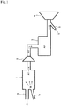
Fig. 1 is a schematic diagram illustrating a basic configuration example of a device for manufacturing high-density air according to the present invention. -
Fig. 2 is a conceptual diagram of raw air, water-containing air, and high-density air. - The best mode for carrying out the present invention will be described below with reference to
Figs. 1 and2 . - In a method for manufacturing high-density air according to the present invention, as illustrated in
Fig. 1 , first, a desired amount of raw air A is supplied into a water-containing air generating means 1 having a sealed space via an air supply means 1a. Next, a large number of fine water particles W are injected to the supplied raw air A through a fine water particle supply means 1b having a jet port such as a nozzle, and the raw air A is mixed with the fine water particles W. - As used in the present invention, the raw air A is preferably air having normal temperature and pressure such as the atmosphere. However, the temperature and pressure of the raw air A can be freely selected and appropriately adjusted in accordance with the implementation of the present invention. Each of the fine water particles W is as fine a water particle (small droplet) as possible in order to increase the surface area, and the particle diameter, temperature, and amount of supply of the fine water particles W are appropriately adjusted, for example, in accordance with the temperature, pressure, and amount of supply of the raw air A.
- As described above, water-containing air A1 is generated by mixing the raw air A with the fine water particles W in the water-containing air generating means 1. Specifically, a large number of fine water particles W mixed in the raw air A are in gas-liquid contact with the raw air A and present in the raw air A while taking the heat of the raw air A. In the present invention, the air containing a large number of fine water particles W is referred to as the water-containing air A1.
- In other words, the fine water particles W are present in the raw air A while holding the heat taken from the raw air A as latent heat of vaporization. Note that the present invention does not exclude a case where part of the fine water particles W in the water-containing air A1 is vaporized into wet steam.
- As described above, the temperature of the water-containing air A1 is lower than that of the raw air A, and accordingly the pressure of the water-containing air A1 is lower than that of the raw air A. As illustrated in
Fig. 2 , the volume of the water-containing air A1 is also smaller than that of the raw air A. - Specifically, assuming that the temperature, pressure, and volume of the raw air A are respectively denoted by T, P, and V (the same applies hereinafter), and the temperature, pressure, and volume of the water-containing air A1 are respectively denoted by T1, P1, and V1 (the same applies hereinafter), then the relations T > T1, P > P1, and V > V1 are satisfied with regard to the temperature, pressure, and volume, respectively.
- Next, as illustrated in
Fig. 1 , the water-containing air A1 passes through a differential pressure supplementing means 2 to be supplemented with a difference in pressure between the raw air A and the water-containing air A1, i.e., a differential pressure (P1 - P) between the pressure P of the raw air A and the pressure P1 of the water-containing air A1, whereby high-density air A2 is manufactured. Since the water-containing air A1 is pressurized to the original pressure P of the raw air A, the generation of heat can be suppressed to a great extent in this case, as compared with a case where the forcible compression is performed, that is, where the raw air A is pressurized to a pressure higher than its original pressure P. In this case, the suppression of heat generation is also achieved through the vaporization of the fine water particles W in the water-containing air A1. - An already known blower machine such as a pressure fan, a fan, and a blower, or an already known known compressor is used as the differential pressure supplementing means 2 to supplement the water-containing air A1 with the differential pressure and transfer the high-density air A2 to a storage means 3 such as a tank. In particular, the blower machine can efficiently supplement the water-containing air A1 with the differential pressure and transfer the high-density air A2 when used as the differential pressure supplementing means 2.
- The temperature and pressure of the manufactured high-density air A2 are higher than those of the water-containing air A1, promoting the vaporization of the fine water particles W. Accordingly, as illustrated in
Fig. 2 , the volume of the high-density air A2 is smaller than that of the water-containing air A1, whereas the pressure of the high-density air A2 is equal to that of the raw air A. - Specifically, assuming that the temperature, pressure, and volume of the high-density air A2 are respectively denoted by T2, P2, and V2 (the same applies hereinafter), then the relations T2 > T1, P = P2 > P1, and V > V1 > V2 are satisfied with regard to the temperature, pressure, and volume, respectively. The temperature T of the raw air A is equal to the temperature T2 of the high-density air A2, or one of the temperatures T and T2 is higher than the other, depending on the amount of contained fine water particles W, the amount of vaporized fine water particles W, and the like.
- As described later, the high-density air A2 manufactured in the above-mentioned manner is supplied for utilization from the storage means 3 to an external combustion engine or an internal combustion engine serving as a heat engine 4.
- Next, a method for utilizing high-density air according to the present invention will be described.
- First, a case where the high-density air A2 manufactured as described above is utilized as an operating gas for an external combustion engine serving as the heat engine 4 will be described. Examples of the external combustion engine include a turbine having an external combustion structure such as an already known steam turbine, an already known free piston, an already known rotary, and the like.
- In this case, the high-density air A2 may be utilized as it is as the operating gas, but preferably it is used together with steam S having a higher pressure than the high-density air A2.
- Specifically, as illustrated in
Fig. 1 , in a case where the heat engine 4 is an external combustion engine, the high-density air A2 is supplied to the external combustion engine 4 together with the steam S that is supplied via a steam supply means 5. - The high-density air A2 and the steam S are simultaneously applied to the external combustion engine 4.
- Alternatively, the high-density air A2 and the steam S are applied to the external combustion engine 4 at a time interval. More specifically, after the operation of the external combustion engine 4 is started by one of the high-density air A2 and the steam S, the other gas is supplied to continue the operation of the external combustion engine 4. Consequently, it is possible to smoothly supply the subsequent gas (the other gas) at a relatively low supply pressure.
- For example, when one gas is supplied, the supply of the other gas is stopped, and when the other gas is supplied, the supply of the one gas is stopped. Alternatively, the supply end of one gas and the supply start of the other gas are synchronized with each other.
- Since the high-density air A2 is a gas that does not condense at the condensation point of the steam S or gas that does not condense at the solidification point of the steam S, the high-density air A2 recovers the heat of condensation or heat of solidification released by the steam S, and inflates itself through the heat recovery to apply its gas pressure to the external combustion engine 4. Therefore, the high-density air A2 can effectively operate the external combustion engine 4 while appropriately receiving the thermal energy of the steam S.
- Note that the present invention does not exclude a case where the temperature, humidity, and pressure of the high-density air A2 are adjusted as necessary for the utilization of the high-density air A2 as the operating gas for the external combustion engine 4.
- Next, a case where the manufactured high-density air A2 is utilized as a combustion supporting gas for an internal combustion engine serving as the heat engine 4 will be described. Examples of the internal combustion engine include a turbine having an internal combustion structure such as an already known gas steam turbine, an engine such as already known hydrogen, gasoline, and jet engines, and an already known boiler.
- In this case, the high-density air A2 is supplied to the internal combustion engine 4, compressed by a cylinder or the like of the internal combustion engine 4, and utilized to enhance the fuel combustion efficiency. The high-density air A2 densely contains a lot of oxygen to effectively improve the combustion efficiency. The high-density air A2 also contains a large number of fine water particles W together with steam, and the fine water particles W are also vaporized into steam and applied to the internal combustion engine.
- Note that the present invention does not exclude a case where the temperature, humidity, and pressure of the high-density air A2 are adjusted as necessary for the utilization of the high-density air A2 as the combustion supporting gas for the internal combustion engine 4.
- As described above, the method for manufacturing high-density air according to the present invention includes mixing the raw air A with the fine water particles W to produce the water-containing air A1 instead of forcibly compressing the raw air A, and supplementing the water-containing air A1 with the differential pressure (P - P1) between the pressure P1 of the water-containing air A1 and the pressure P of the raw air A. Consequently, it is possible to efficiently manufacture the high-density air A2 without unnecessarily increasing the temperature and pressure and thus without causing energy loss such as the loss of thermal energy due to the increase and subsequent decrease in the temperature.
- In addition, if the high-density air A2 manufactured with the above method is utilized as the operating gas for the external combustion engine together with the steam S having a higher pressure than the high-density air A2, the external combustion engine can be effectively operated.
- Further, if the high-density air A2 manufactured with the above method is utilized as the combustion supporting gas for the internal combustion engine, the combustion efficiency in the internal combustion engine can be effectively improved.
-
- 1 water-containing air generating means
- 1a air supply means
- 1b fine water particle supply means
- 2 differential pressure supplementing means (blower machine or compressor)
- 3 storage means
- 4 heat engine (external combustion engine or internal combustion engine)
- 5 steam supply means
- A raw air
- A1 water-containing air
- A2 high-density air
- W fine water particles
- S steam.
Claims (7)
- A method for manufacturing high-density air, the method comprising:mixing raw air with fine water particles to generate water-containing air having a lower pressure than the raw air;supplementing the water-containing air with a differential pressure between a pressure of the raw air and a pressure of the water-containing air; andconsequently promoting vaporization of the fine water particles in the water-containing air and reducing a volume of the water-containing air to manufacture high-density air.
- The method for manufacturing high-density air according to claim 1, wherein
a blower machine is used as a means for supplementing the pressure of the water-containing air. - The method for manufacturing high-density air according to claim 1, wherein
a compressor is used as a means for supplementing the pressure of the water-containing air. - A method for utilizing high-density air, the method comprising:utilizing, as an operating gas for an external combustion engine, high-density air manufactured with the method according to any one of claims 1 to 3 together with steam having a higher pressure than the high-density air.
- The method for utilizing high-density air according to claim 4, wherein
the high-density air and the steam are simultaneously applied to the external combustion engine. - The method for utilizing high-density air according to claim 4, wherein
the high-density air and the steam are applied to the external combustion engine at a time interval. - A method for utilizing high-density air, the method comprising:utilizing, as a combustion supporting gas for an internal combustion engine, high-density air manufactured with the method according to any one of claims 1 to 3.
Priority Applications (5)
| Application Number | Priority Date | Filing Date | Title |
|---|---|---|---|
| RS20201581A RS61375B1 (en) | 2015-05-13 | 2016-01-13 | Method for producing high-density air and method for using same |
| PL16792390T PL3296569T3 (en) | 2015-05-13 | 2016-01-13 | HOW TO GENERATE HIGH DENSITY AIR AND HOW TO USE IT |
| SM20210023T SMT202100023T1 (en) | 2015-05-13 | 2016-01-13 | Method for producing high-density air and method for using same |
| SI201631050T SI3296569T1 (en) | 2015-05-13 | 2016-01-13 | Method for producing high-density air and method for using same |
| HRP20210050TT HRP20210050T8 (en) | 2015-05-13 | 2016-01-13 | Method for producing high-density air and method for using same |
Applications Claiming Priority (2)
| Application Number | Priority Date | Filing Date | Title |
|---|---|---|---|
| JP2015098523A JP5778369B1 (en) | 2015-05-13 | 2015-05-13 | Method for producing and using high-density air |
| PCT/JP2016/050818 WO2016181664A1 (en) | 2015-05-13 | 2016-01-13 | Method for producing high-density air and method for using same |
Publications (3)
| Publication Number | Publication Date |
|---|---|
| EP3296569A1 true EP3296569A1 (en) | 2018-03-21 |
| EP3296569A4 EP3296569A4 (en) | 2018-11-21 |
| EP3296569B1 EP3296569B1 (en) | 2020-11-04 |
Family
ID=54192747
Family Applications (1)
| Application Number | Title | Priority Date | Filing Date |
|---|---|---|---|
| EP16792390.3A Active EP3296569B1 (en) | 2015-05-13 | 2016-01-13 | Method for producing high-density air and method for using same |
Country Status (26)
| Country | Link |
|---|---|
| US (1) | US11506120B2 (en) |
| EP (1) | EP3296569B1 (en) |
| JP (1) | JP5778369B1 (en) |
| KR (1) | KR102455330B1 (en) |
| CN (1) | CN107614872A (en) |
| AU (1) | AU2016261407B2 (en) |
| BR (1) | BR112017023954B1 (en) |
| CY (1) | CY1123848T1 (en) |
| DK (1) | DK3296569T3 (en) |
| ES (1) | ES2843695T3 (en) |
| HK (1) | HK1244862A1 (en) |
| HR (1) | HRP20210050T8 (en) |
| HU (1) | HUE053416T2 (en) |
| LT (1) | LT3296569T (en) |
| MX (1) | MX389151B (en) |
| MY (1) | MY186855A (en) |
| PH (1) | PH12017502047B1 (en) |
| PL (1) | PL3296569T3 (en) |
| PT (1) | PT3296569T (en) |
| RS (1) | RS61375B1 (en) |
| RU (1) | RU2017140041A (en) |
| SI (1) | SI3296569T1 (en) |
| SM (1) | SMT202100023T1 (en) |
| TW (1) | TWI695145B (en) |
| WO (1) | WO2016181664A1 (en) |
| ZA (1) | ZA201707391B (en) |
Families Citing this family (3)
| Publication number | Priority date | Publication date | Assignee | Title |
|---|---|---|---|---|
| CN105715519A (en) * | 2016-02-02 | 2016-06-29 | 娄伟 | Fan system utilizing latent heat of vaporization to achieve pressurization |
| JP6363313B1 (en) * | 2018-03-01 | 2018-07-25 | 隆逸 小林 | Working medium characteristic difference power generation system and working medium characteristic difference power generation method using the power generation system |
| USD1112554S1 (en) | 2024-05-07 | 2026-02-10 | Karen Tefft | Pickleball paddle |
Family Cites Families (33)
| Publication number | Priority date | Publication date | Assignee | Title |
|---|---|---|---|---|
| US4631914A (en) * | 1985-02-25 | 1986-12-30 | General Electric Company | Gas turbine engine of improved thermal efficiency |
| DE4015818A1 (en) * | 1990-05-17 | 1991-04-04 | Daimler Benz Ag | FULL CONDITIONING FOR COMBUSTION AIR AND EXHAUST GAS ON TESTS FOR COMBUSTION ENGINES |
| US5282726A (en) * | 1991-06-21 | 1994-02-01 | Praxair Technology, Inc. | Compressor supercharger with evaporative cooler |
| US5617719A (en) * | 1992-10-27 | 1997-04-08 | Ginter; J. Lyell | Vapor-air steam engine |
| CA2088947C (en) * | 1993-02-05 | 1996-07-16 | Daniel A. Warkentin | Hydrogen fuelled gas turbine |
| IL110361A (en) * | 1993-07-22 | 2003-03-12 | Ormat Ind Ltd | Method of and apparatus for augmenting power produced by gas turbines |
| US5867977A (en) * | 1996-05-14 | 1999-02-09 | The Dow Chemical Company | Method and apparatus for achieving power augmentation in gas turbines via wet compression |
| JPH1077980A (en) * | 1996-08-30 | 1998-03-24 | Ishikawajima Harima Heavy Ind Co Ltd | Air compression equipment |
| US6389799B1 (en) * | 1997-04-22 | 2002-05-21 | Hitachi, Ltd. | Gas turbine Installation |
| JP2000034930A (en) * | 1998-07-17 | 2000-02-02 | Ishikawajima Harima Heavy Ind Co Ltd | Compressed air supply device |
| US6321539B1 (en) * | 1998-09-10 | 2001-11-27 | Ormat Industries Ltd. | Retrofit equipment for reducing the consumption of fossil fuel by a power plant using solar insolation |
| JP2000120596A (en) * | 1998-10-12 | 2000-04-25 | Ishikawajima Harima Heavy Ind Co Ltd | Water spray device for turbo compressor |
| DE19852060A1 (en) * | 1998-11-11 | 2000-05-25 | Steag Ag | Method and device for conditioning supply air for an engine or machine |
| US7096659B1 (en) * | 2000-01-21 | 2006-08-29 | Hitachi, Ltd. | Gas turbine electric power generation equipment and air humidifier |
| MXPA03004561A (en) * | 2000-11-22 | 2003-09-10 | Avl List Gmbh | Method for supplying an internal combustion engine with conditioned combustion gas, device for carrying out said method, method for determining the quantities of pollutants in the exhaust gases of an internal combustion engine, and device for carryin |
| JP3801041B2 (en) * | 2001-12-12 | 2006-07-26 | 株式会社日立製作所 | Water jet screw compressor |
| SE0301585D0 (en) * | 2003-05-30 | 2003-05-30 | Euroturbine Ab | Procedure for operating a gas turbine group |
| JP4804903B2 (en) | 2005-12-09 | 2011-11-02 | 株式会社神戸製鋼所 | Compressed air generation method and compressed air generation system |
| CN2916184Y (en) * | 2006-04-05 | 2007-06-27 | 张礼明 | High-purity compression gas generation system |
| FR2924109B1 (en) | 2007-11-26 | 2010-11-26 | Air Liquide | PROCESS AND INSTALLATION FOR PRODUCING A COOLED AND COMPRESSED SYNTHESIS GAS |
| JP2009191635A (en) * | 2008-02-12 | 2009-08-27 | Ihi Corp | Gas machine |
| JP5248373B2 (en) * | 2009-03-11 | 2013-07-31 | 株式会社日立産機システム | Water jet air compressor |
| GB0917319D0 (en) * | 2009-10-05 | 2009-11-18 | Rolls Royce Plc | An apparatus and method of operating a gas turbine engine |
| EP2623741B1 (en) * | 2010-09-30 | 2018-11-28 | Mitsubishi Hitachi Power Systems, Ltd. | Combined cycle power generation plant utilzing solar heat |
| GB201100602D0 (en) * | 2011-01-14 | 2011-03-02 | Rolls Royce Plc | Gas turbine engine |
| KR20120095489A (en) * | 2011-02-19 | 2012-08-29 | 윤장식 | Centrifugal wet type sweeper |
| WO2012120555A1 (en) * | 2011-03-07 | 2012-09-13 | 株式会社 日立製作所 | Solar heat utilization gas turbine system |
| JP6010348B2 (en) * | 2012-06-01 | 2016-10-19 | 三菱日立パワーシステムズ株式会社 | Axial flow compressor and gas turbine provided with the same |
| JP6109529B2 (en) * | 2012-10-31 | 2017-04-05 | 三菱日立パワーシステムズ株式会社 | Power generation system |
| JP6092613B2 (en) * | 2012-12-26 | 2017-03-08 | 三菱日立パワーシステムズ株式会社 | Axial flow compressor and operation method of axial flow compressor |
| JP2015014207A (en) * | 2013-07-03 | 2015-01-22 | 株式会社東芝 | Erosion reduction device for gas turbine compressor |
| JP2015090090A (en) * | 2013-11-05 | 2015-05-11 | 三菱日立パワーシステムズ株式会社 | Intake spray device and gas turbine equipment |
| JP6483510B2 (en) * | 2015-04-14 | 2019-03-13 | 三菱日立パワーシステムズ株式会社 | Gas turbine manufacturing method |
-
2015
- 2015-05-13 JP JP2015098523A patent/JP5778369B1/en not_active Expired - Fee Related
-
2016
- 2016-01-13 EP EP16792390.3A patent/EP3296569B1/en active Active
- 2016-01-13 CN CN201680027126.5A patent/CN107614872A/en active Pending
- 2016-01-13 SI SI201631050T patent/SI3296569T1/en unknown
- 2016-01-13 MY MYPI2017704045A patent/MY186855A/en unknown
- 2016-01-13 AU AU2016261407A patent/AU2016261407B2/en not_active Ceased
- 2016-01-13 WO PCT/JP2016/050818 patent/WO2016181664A1/en not_active Ceased
- 2016-01-13 DK DK16792390.3T patent/DK3296569T3/en active
- 2016-01-13 PT PT167923903T patent/PT3296569T/en unknown
- 2016-01-13 US US15/572,629 patent/US11506120B2/en active Active
- 2016-01-13 RU RU2017140041A patent/RU2017140041A/en unknown
- 2016-01-13 HK HK18104274.9A patent/HK1244862A1/en unknown
- 2016-01-13 HU HUE16792390A patent/HUE053416T2/en unknown
- 2016-01-13 SM SM20210023T patent/SMT202100023T1/en unknown
- 2016-01-13 MX MX2017014392A patent/MX389151B/en unknown
- 2016-01-13 BR BR112017023954-0A patent/BR112017023954B1/en not_active IP Right Cessation
- 2016-01-13 ES ES16792390T patent/ES2843695T3/en active Active
- 2016-01-13 RS RS20201581A patent/RS61375B1/en unknown
- 2016-01-13 HR HRP20210050TT patent/HRP20210050T8/en unknown
- 2016-01-13 KR KR1020177033042A patent/KR102455330B1/en active Active
- 2016-01-13 LT LTEP16792390.3T patent/LT3296569T/en unknown
- 2016-01-13 PL PL16792390T patent/PL3296569T3/en unknown
- 2016-01-21 TW TW105101863A patent/TWI695145B/en not_active IP Right Cessation
-
2017
- 2017-10-31 ZA ZA2017/07391A patent/ZA201707391B/en unknown
- 2017-11-09 PH PH12017502047A patent/PH12017502047B1/en unknown
-
2021
- 2021-01-14 CY CY20211100029T patent/CY1123848T1/en unknown
Also Published As
Similar Documents
| Publication | Publication Date | Title |
|---|---|---|
| US20220412263A1 (en) | Engine using heated and turbo-expanded ammonia fuel | |
| CN101230799A (en) | Gas turbine power augmentation by expander cold exhaust injection upstream of combustor | |
| CN108716783B (en) | A back pressure injection transcritical CO2 power cycle power generation system | |
| KR102536353B1 (en) | Combined power plant and operating method of the same | |
| US11506120B2 (en) | Method for manufacturing and utilizing high-density air | |
| CN101892878B (en) | Method and system for use with an integrated gasification combined cycle plant | |
| KR20090019759A (en) | Single Circulation Heat Pump Generator | |
| CN102410109A (en) | Engine waste heat energy recovery method and device | |
| CN105134318A (en) | Energy storage device based on hydrogen-steam turbine compound cycle | |
| CN114810252A (en) | Supercritical CO 2 Variable-load working medium charging and discharging system and method for generator set | |
| JP2010235736A (en) | Synthetic fuel production system | |
| CN115306500A (en) | Transcritical compressed carbon dioxide energy storage system and operation method thereof | |
| JP2015536396A (en) | Heat engine | |
| CN107559179B (en) | A kind of compressed-air energy storage overbottom pressure utilization system | |
| OA18458A (en) | Method for producing high-density air and method for using same | |
| JP2021508018A (en) | Internal combustion engine residual heat utilization system | |
| KR101378994B1 (en) | Power generator by using waste gas heat in vehicle engine | |
| RU2776883C2 (en) | Method for producing and utilising high-density air | |
| JPH0211826A (en) | Inert gas circulation hydrogen fuel internal combustion engine | |
| CN218915437U (en) | Geothermal energy utilization system for combined cooling and power generation and carbon sequestration | |
| JP2010174888A (en) | Gas turbine with introduction of nitrogen | |
| CN111463806A (en) | A power storage peak regulation system | |
| CN103334848A (en) | Heat recovery power generation system of engine | |
| JP2006240972A (en) | Hydrogen fuel self-feeding apparatus | |
| CN117189486A (en) | Humidified compressed air energy storage system for offshore wind turbines |
Legal Events
| Date | Code | Title | Description |
|---|---|---|---|
| STAA | Information on the status of an ep patent application or granted ep patent |
Free format text: STATUS: THE INTERNATIONAL PUBLICATION HAS BEEN MADE |
|
| PUAI | Public reference made under article 153(3) epc to a published international application that has entered the european phase |
Free format text: ORIGINAL CODE: 0009012 |
|
| STAA | Information on the status of an ep patent application or granted ep patent |
Free format text: STATUS: REQUEST FOR EXAMINATION WAS MADE |
|
| 17P | Request for examination filed |
Effective date: 20171123 |
|
| AK | Designated contracting states |
Kind code of ref document: A1 Designated state(s): AL AT BE BG CH CY CZ DE DK EE ES FI FR GB GR HR HU IE IS IT LI LT LU LV MC MK MT NL NO PL PT RO RS SE SI SK SM TR |
|
| AX | Request for extension of the european patent |
Extension state: BA ME |
|
| DAV | Request for validation of the european patent (deleted) | ||
| DAX | Request for extension of the european patent (deleted) | ||
| REG | Reference to a national code |
Ref country code: DE Ref legal event code: R079 Ref document number: 602016047290 Country of ref document: DE Free format text: PREVIOUS MAIN CLASS: F04B0039060000 Ipc: F02C0003300000 |
|
| A4 | Supplementary search report drawn up and despatched |
Effective date: 20181022 |
|
| RIC1 | Information provided on ipc code assigned before grant |
Ipc: F02B 29/04 20060101ALI20181016BHEP Ipc: F02C 3/22 20060101ALI20181016BHEP Ipc: F02M 25/035 20060101ALI20181016BHEP Ipc: F04B 39/06 20060101ALI20181016BHEP Ipc: F02M 25/028 20060101ALI20181016BHEP Ipc: F23L 7/00 20060101ALI20181016BHEP Ipc: F02C 3/30 20060101AFI20181016BHEP Ipc: F02C 7/143 20060101ALI20181016BHEP Ipc: F02M 33/00 20060101ALI20181016BHEP Ipc: F02M 25/032 20060101ALI20181016BHEP |
|
| STAA | Information on the status of an ep patent application or granted ep patent |
Free format text: STATUS: EXAMINATION IS IN PROGRESS |
|
| 17Q | First examination report despatched |
Effective date: 20190520 |
|
| GRAP | Despatch of communication of intention to grant a patent |
Free format text: ORIGINAL CODE: EPIDOSNIGR1 |
|
| STAA | Information on the status of an ep patent application or granted ep patent |
Free format text: STATUS: GRANT OF PATENT IS INTENDED |
|
| INTG | Intention to grant announced |
Effective date: 20200720 |
|
| GRAS | Grant fee paid |
Free format text: ORIGINAL CODE: EPIDOSNIGR3 |
|
| GRAA | (expected) grant |
Free format text: ORIGINAL CODE: 0009210 |
|
| STAA | Information on the status of an ep patent application or granted ep patent |
Free format text: STATUS: THE PATENT HAS BEEN GRANTED |
|
| AK | Designated contracting states |
Kind code of ref document: B1 Designated state(s): AL AT BE BG CH CY CZ DE DK EE ES FI FR GB GR HR HU IE IS IT LI LT LU LV MC MK MT NL NO PL PT RO RS SE SI SK SM TR |
|
| REG | Reference to a national code |
Ref country code: GB Ref legal event code: FG4D |
|
| REG | Reference to a national code |
Ref country code: CH Ref legal event code: EP |
|
| REG | Reference to a national code |
Ref country code: AT Ref legal event code: REF Ref document number: 1331097 Country of ref document: AT Kind code of ref document: T Effective date: 20201115 |
|
| REG | Reference to a national code |
Ref country code: DE Ref legal event code: R096 Ref document number: 602016047290 Country of ref document: DE |
|
| REG | Reference to a national code |
Ref country code: IE Ref legal event code: FG4D |
|
| REG | Reference to a national code |
Ref country code: RO Ref legal event code: EPE |
|
| REG | Reference to a national code |
Ref country code: HR Ref legal event code: TUEP Ref document number: P20210050T Country of ref document: HR |
|
| REG | Reference to a national code |
Ref country code: DK Ref legal event code: T3 Effective date: 20210115 Ref country code: FI Ref legal event code: FGE |
|
| REG | Reference to a national code |
Ref country code: PT Ref legal event code: SC4A Ref document number: 3296569 Country of ref document: PT Date of ref document: 20210120 Kind code of ref document: T Free format text: AVAILABILITY OF NATIONAL TRANSLATION Effective date: 20210114 |
|
| REG | Reference to a national code |
Ref country code: SE Ref legal event code: TRGR |
|
| REG | Reference to a national code |
Ref country code: NL Ref legal event code: FP |
|
| REG | Reference to a national code |
Ref country code: CH Ref legal event code: NV Representative=s name: VALIPAT S.A. C/O BOVARD SA NEUCHATEL, CH |
|
| REG | Reference to a national code |
Ref country code: HR Ref legal event code: ODRP Ref document number: P20210050T Country of ref document: HR Payment date: 20210113 Year of fee payment: 6 |
|
| REG | Reference to a national code |
Ref country code: GR Ref legal event code: EP Ref document number: 20210400147 Country of ref document: GR Effective date: 20210215 |
|
| REG | Reference to a national code |
Ref country code: EE Ref legal event code: FG4A Ref document number: E020340 Country of ref document: EE Effective date: 20210118 |
|
| REG | Reference to a national code |
Ref country code: HR Ref legal event code: T1PR Ref document number: P20210050 Country of ref document: HR |
|
| REG | Reference to a national code |
Ref country code: SK Ref legal event code: T3 Ref document number: E 36494 Country of ref document: SK |
|
| REG | Reference to a national code |
Ref country code: NO Ref legal event code: T2 Effective date: 20201104 |
|
| REG | Reference to a national code |
Ref country code: ES Ref legal event code: FG2A Ref document number: 2843695 Country of ref document: ES Kind code of ref document: T3 Effective date: 20210720 |
|
| REG | Reference to a national code |
Ref country code: HU Ref legal event code: AG4A Ref document number: E053416 Country of ref document: HU |
|
| REG | Reference to a national code |
Ref country code: DE Ref legal event code: R097 Ref document number: 602016047290 Country of ref document: DE |
|
| PLBE | No opposition filed within time limit |
Free format text: ORIGINAL CODE: 0009261 |
|
| STAA | Information on the status of an ep patent application or granted ep patent |
Free format text: STATUS: NO OPPOSITION FILED WITHIN TIME LIMIT |
|
| 26N | No opposition filed |
Effective date: 20210805 |
|
| REG | Reference to a national code |
Ref country code: HR Ref legal event code: ODRP Ref document number: P20210050 Country of ref document: HR Payment date: 20220104 Year of fee payment: 7 |
|
| REG | Reference to a national code |
Ref country code: HR Ref legal event code: ODRP Ref document number: P20210050 Country of ref document: HR Payment date: 20221207 Year of fee payment: 8 |
|
| REG | Reference to a national code |
Ref country code: HR Ref legal event code: T8IS Ref document number: P20210050 Country of ref document: HR |
|
| REG | Reference to a national code |
Ref country code: AT Ref legal event code: UEP Ref document number: 1331097 Country of ref document: AT Kind code of ref document: T Effective date: 20201104 |
|
| REG | Reference to a national code |
Ref country code: HR Ref legal event code: ODRP Ref document number: P20210050 Country of ref document: HR Payment date: 20231221 Year of fee payment: 9 |
|
| PGFP | Annual fee paid to national office [announced via postgrant information from national office to epo] |
Ref country code: IS Payment date: 20231218 Year of fee payment: 9 |
|
| PGFP | Annual fee paid to national office [announced via postgrant information from national office to epo] |
Ref country code: SM Payment date: 20231218 Year of fee payment: 9 Ref country code: RS Payment date: 20231215 Year of fee payment: 9 Ref country code: PT Payment date: 20231220 Year of fee payment: 9 Ref country code: MT Payment date: 20231228 Year of fee payment: 9 Ref country code: LV Payment date: 20231218 Year of fee payment: 9 Ref country code: LT Payment date: 20231221 Year of fee payment: 9 Ref country code: HR Payment date: 20231221 Year of fee payment: 9 Ref country code: EE Payment date: 20231215 Year of fee payment: 9 Ref country code: BG Payment date: 20231214 Year of fee payment: 9 |
|
| PGFP | Annual fee paid to national office [announced via postgrant information from national office to epo] |
Ref country code: NL Payment date: 20240123 Year of fee payment: 9 |
|
| PGFP | Annual fee paid to national office [announced via postgrant information from national office to epo] |
Ref country code: LU Payment date: 20240122 Year of fee payment: 9 |
|
| PGFP | Annual fee paid to national office [announced via postgrant information from national office to epo] |
Ref country code: MK Payment date: 20231220 Year of fee payment: 9 |
|
| PGFP | Annual fee paid to national office [announced via postgrant information from national office to epo] |
Ref country code: GR Payment date: 20240129 Year of fee payment: 9 |
|
| PGFP | Annual fee paid to national office [announced via postgrant information from national office to epo] |
Ref country code: IE Payment date: 20240109 Year of fee payment: 9 Ref country code: ES Payment date: 20240206 Year of fee payment: 9 |
|
| PGFP | Annual fee paid to national office [announced via postgrant information from national office to epo] |
Ref country code: AT Payment date: 20240126 Year of fee payment: 9 |
|
| PGFP | Annual fee paid to national office [announced via postgrant information from national office to epo] |
Ref country code: MC Payment date: 20240109 Year of fee payment: 9 |
|
| PGFP | Annual fee paid to national office [announced via postgrant information from national office to epo] |
Ref country code: RO Payment date: 20240108 Year of fee payment: 9 Ref country code: HU Payment date: 20240111 Year of fee payment: 9 Ref country code: FI Payment date: 20240125 Year of fee payment: 9 Ref country code: DE Payment date: 20240125 Year of fee payment: 9 Ref country code: CZ Payment date: 20240108 Year of fee payment: 9 Ref country code: GB Payment date: 20240126 Year of fee payment: 9 Ref country code: SK Payment date: 20240103 Year of fee payment: 9 Ref country code: CH Payment date: 20240202 Year of fee payment: 9 |
|
| PGFP | Annual fee paid to national office [announced via postgrant information from national office to epo] |
Ref country code: SI Payment date: 20240112 Year of fee payment: 9 |
|
| PGFP | Annual fee paid to national office [announced via postgrant information from national office to epo] |
Ref country code: TR Payment date: 20240108 Year of fee payment: 9 Ref country code: SE Payment date: 20240109 Year of fee payment: 9 Ref country code: PL Payment date: 20240109 Year of fee payment: 9 Ref country code: NO Payment date: 20240110 Year of fee payment: 9 Ref country code: IT Payment date: 20240123 Year of fee payment: 9 Ref country code: FR Payment date: 20240124 Year of fee payment: 9 Ref country code: DK Payment date: 20240108 Year of fee payment: 9 Ref country code: BE Payment date: 20240122 Year of fee payment: 9 |
|
| PGFP | Annual fee paid to national office [announced via postgrant information from national office to epo] |
Ref country code: AL Payment date: 20231215 Year of fee payment: 9 |
|
| PGFP | Annual fee paid to national office [announced via postgrant information from national office to epo] |
Ref country code: CY Payment date: 20240607 Year of fee payment: 9 |
|
| REG | Reference to a national code |
Ref country code: HR Ref legal event code: PBON Ref document number: P20210050 Country of ref document: HR Effective date: 20250113 |
|
| REG | Reference to a national code |
Ref country code: DE Ref legal event code: R119 Ref document number: 602016047290 Country of ref document: DE |
|
| REG | Reference to a national code |
Ref country code: LT Ref legal event code: MM4D Effective date: 20250113 |
|
| REG | Reference to a national code |
Ref country code: DK Ref legal event code: EBP Effective date: 20250131 |
|
| REG | Reference to a national code |
Ref country code: SK Ref legal event code: MM4A Ref document number: E 36494 Country of ref document: SK Effective date: 20250113 |
|
| REG | Reference to a national code |
Ref country code: CH Ref legal event code: PL |
|
| REG | Reference to a national code |
Ref country code: SE Ref legal event code: EUG |
|
| REG | Reference to a national code |
Ref country code: NL Ref legal event code: MM Effective date: 20250201 |
|
| PG25 | Lapsed in a contracting state [announced via postgrant information from national office to epo] |
Ref country code: MC Free format text: LAPSE BECAUSE OF NON-PAYMENT OF DUE FEES Effective date: 20250131 Ref country code: LU Free format text: LAPSE BECAUSE OF NON-PAYMENT OF DUE FEES Effective date: 20250113 |
|
| REG | Reference to a national code |
Ref country code: AT Ref legal event code: MM01 Ref document number: 1331097 Country of ref document: AT Kind code of ref document: T Effective date: 20250113 |
|
| PG25 | Lapsed in a contracting state [announced via postgrant information from national office to epo] |
Ref country code: HU Free format text: LAPSE BECAUSE OF NON-PAYMENT OF DUE FEES Effective date: 20250114 |
|
| GBPC | Gb: european patent ceased through non-payment of renewal fee |
Effective date: 20250113 |
|
| PG25 | Lapsed in a contracting state [announced via postgrant information from national office to epo] |
Ref country code: SM Free format text: LAPSE BECAUSE OF NON-PAYMENT OF DUE FEES Effective date: 20250812 |
|
| PG25 | Lapsed in a contracting state [announced via postgrant information from national office to epo] |
Ref country code: PT Free format text: LAPSE BECAUSE OF NON-PAYMENT OF DUE FEES Effective date: 20250714 |
|
| PG25 | Lapsed in a contracting state [announced via postgrant information from national office to epo] |
Ref country code: DE Free format text: LAPSE BECAUSE OF NON-PAYMENT OF DUE FEES Effective date: 20250801 Ref country code: LT Free format text: LAPSE BECAUSE OF NON-PAYMENT OF DUE FEES Effective date: 20250113 Ref country code: FI Free format text: LAPSE BECAUSE OF NON-PAYMENT OF DUE FEES Effective date: 20250113 |
|
| PG25 | Lapsed in a contracting state [announced via postgrant information from national office to epo] |
Ref country code: GR Free format text: LAPSE BECAUSE OF NON-PAYMENT OF DUE FEES Effective date: 20250805 Ref country code: NO Free format text: LAPSE BECAUSE OF NON-PAYMENT OF DUE FEES Effective date: 20250131 |
|
| PG25 | Lapsed in a contracting state [announced via postgrant information from national office to epo] |
Ref country code: NL Free format text: LAPSE BECAUSE OF NON-PAYMENT OF DUE FEES Effective date: 20250201 |
|
| PG25 | Lapsed in a contracting state [announced via postgrant information from national office to epo] |
Ref country code: GB Free format text: LAPSE BECAUSE OF NON-PAYMENT OF DUE FEES Effective date: 20250113 Ref country code: BG Free format text: LAPSE BECAUSE OF NON-PAYMENT OF DUE FEES Effective date: 20250113 Ref country code: BE Free format text: LAPSE BECAUSE OF NON-PAYMENT OF DUE FEES Effective date: 20250131 |
|
| PG25 | Lapsed in a contracting state [announced via postgrant information from national office to epo] |
Ref country code: HR Free format text: LAPSE BECAUSE OF NON-PAYMENT OF DUE FEES Effective date: 20250113 |
|
| PG25 | Lapsed in a contracting state [announced via postgrant information from national office to epo] |
Ref country code: AT Free format text: LAPSE BECAUSE OF NON-PAYMENT OF DUE FEES Effective date: 20250113 Ref country code: FR Free format text: LAPSE BECAUSE OF NON-PAYMENT OF DUE FEES Effective date: 20250131 |
|
| PG25 | Lapsed in a contracting state [announced via postgrant information from national office to epo] |
Ref country code: CY Free format text: LAPSE BECAUSE OF NON-PAYMENT OF DUE FEES Effective date: 20250113 Ref country code: CH Free format text: LAPSE BECAUSE OF NON-PAYMENT OF DUE FEES Effective date: 20250131 |
|
| PG25 | Lapsed in a contracting state [announced via postgrant information from national office to epo] |
Ref country code: RS Free format text: LAPSE BECAUSE OF NON-PAYMENT OF DUE FEES Effective date: 20250113 Ref country code: EE Free format text: LAPSE BECAUSE OF NON-PAYMENT OF DUE FEES Effective date: 20250131 Ref country code: CZ Free format text: LAPSE BECAUSE OF NON-PAYMENT OF DUE FEES Effective date: 20250113 |
|
| REG | Reference to a national code |
Ref country code: BE Ref legal event code: MM Effective date: 20250131 |
|
| PG25 | Lapsed in a contracting state [announced via postgrant information from national office to epo] |
Ref country code: RO Free format text: LAPSE BECAUSE OF NON-PAYMENT OF DUE FEES Effective date: 20250113 |
|
| PG25 | Lapsed in a contracting state [announced via postgrant information from national office to epo] |
Ref country code: SK Free format text: LAPSE BECAUSE OF NON-PAYMENT OF DUE FEES Effective date: 20250113 |
|
| PG25 | Lapsed in a contracting state [announced via postgrant information from national office to epo] |
Ref country code: LV Free format text: LAPSE BECAUSE OF NON-PAYMENT OF DUE FEES Effective date: 20250113 |
|
| PG25 | Lapsed in a contracting state [announced via postgrant information from national office to epo] |
Ref country code: DK Free format text: LAPSE BECAUSE OF NON-PAYMENT OF DUE FEES Effective date: 20250131 |
|
| PG25 | Lapsed in a contracting state [announced via postgrant information from national office to epo] |
Ref country code: IT Free format text: LAPSE BECAUSE OF NON-PAYMENT OF DUE FEES Effective date: 20250113 |
|
| PG25 | Lapsed in a contracting state [announced via postgrant information from national office to epo] |
Ref country code: IE Free format text: LAPSE BECAUSE OF NON-PAYMENT OF DUE FEES Effective date: 20250113 |
|
| REG | Reference to a national code |
Ref country code: SI Ref legal event code: KO00 Effective date: 20250114 |
|
| REG | Reference to a national code |
Ref country code: ES Ref legal event code: FD2A Effective date: 20260227 |
|
| PG25 | Lapsed in a contracting state [announced via postgrant information from national office to epo] |
Ref country code: ES Free format text: LAPSE BECAUSE OF NON-PAYMENT OF DUE FEES Effective date: 20250114 |
|
| PG25 | Lapsed in a contracting state [announced via postgrant information from national office to epo] |
Ref country code: PL Free format text: LAPSE BECAUSE OF NON-PAYMENT OF DUE FEES Effective date: 20250113 |