EP3296536A1 - Dispositif de refroidissement, en particulier pour un véhicule automobile - Google Patents
Dispositif de refroidissement, en particulier pour un véhicule automobile Download PDFInfo
- Publication number
- EP3296536A1 EP3296536A1 EP16188772.4A EP16188772A EP3296536A1 EP 3296536 A1 EP3296536 A1 EP 3296536A1 EP 16188772 A EP16188772 A EP 16188772A EP 3296536 A1 EP3296536 A1 EP 3296536A1
- Authority
- EP
- European Patent Office
- Prior art keywords
- container
- cooling device
- heat exchanger
- gas
- coolant
- Prior art date
- Legal status (The legal status is an assumption and is not a legal conclusion. Google has not performed a legal analysis and makes no representation as to the accuracy of the status listed.)
- Withdrawn
Links
Images


Classifications
-
- F—MECHANICAL ENGINEERING; LIGHTING; HEATING; WEAPONS; BLASTING
- F02—COMBUSTION ENGINES; HOT-GAS OR COMBUSTION-PRODUCT ENGINE PLANTS
- F02B—INTERNAL-COMBUSTION PISTON ENGINES; COMBUSTION ENGINES IN GENERAL
- F02B29/00—Engines characterised by provision for charging or scavenging not provided for in groups F02B25/00, F02B27/00 or F02B33/00 - F02B39/00; Details thereof
- F02B29/04—Cooling of air intake supply
- F02B29/045—Constructional details of the heat exchangers, e.g. pipes, plates, ribs, insulation, materials, or manufacturing and assembly
- F02B29/0462—Liquid cooled heat exchangers
-
- F—MECHANICAL ENGINEERING; LIGHTING; HEATING; WEAPONS; BLASTING
- F28—HEAT EXCHANGE IN GENERAL
- F28D—HEAT-EXCHANGE APPARATUS, NOT PROVIDED FOR IN ANOTHER SUBCLASS, IN WHICH THE HEAT-EXCHANGE MEDIA DO NOT COME INTO DIRECT CONTACT
- F28D7/00—Heat-exchange apparatus having stationary tubular conduit assemblies for both heat-exchange media, the media being in contact with different sides of a conduit wall
- F28D7/16—Heat-exchange apparatus having stationary tubular conduit assemblies for both heat-exchange media, the media being in contact with different sides of a conduit wall the conduits being arranged in parallel spaced relation
- F28D7/1684—Heat-exchange apparatus having stationary tubular conduit assemblies for both heat-exchange media, the media being in contact with different sides of a conduit wall the conduits being arranged in parallel spaced relation the conduits having a non-circular cross-section
- F28D7/1692—Heat-exchange apparatus having stationary tubular conduit assemblies for both heat-exchange media, the media being in contact with different sides of a conduit wall the conduits being arranged in parallel spaced relation the conduits having a non-circular cross-section with particular pattern of flow of the heat exchange media, e.g. change of flow direction
-
- F—MECHANICAL ENGINEERING; LIGHTING; HEATING; WEAPONS; BLASTING
- F28—HEAT EXCHANGE IN GENERAL
- F28D—HEAT-EXCHANGE APPARATUS, NOT PROVIDED FOR IN ANOTHER SUBCLASS, IN WHICH THE HEAT-EXCHANGE MEDIA DO NOT COME INTO DIRECT CONTACT
- F28D9/00—Heat-exchange apparatus having stationary plate-like or laminated conduit assemblies for both heat-exchange media, the media being in contact with different sides of a conduit wall
- F28D9/0031—Heat-exchange apparatus having stationary plate-like or laminated conduit assemblies for both heat-exchange media, the media being in contact with different sides of a conduit wall the conduits for one heat-exchange medium being formed by paired plates touching each other
-
- F—MECHANICAL ENGINEERING; LIGHTING; HEATING; WEAPONS; BLASTING
- F28—HEAT EXCHANGE IN GENERAL
- F28F—DETAILS OF HEAT-EXCHANGE AND HEAT-TRANSFER APPARATUS, OF GENERAL APPLICATION
- F28F9/00—Casings; Header boxes; Auxiliary supports for elements; Auxiliary members within casings
- F28F9/02—Header boxes; End plates
- F28F9/0246—Arrangements for connecting header boxes with flow lines
- F28F9/0251—Massive connectors, e.g. blocks; Plate-like connectors
-
- F—MECHANICAL ENGINEERING; LIGHTING; HEATING; WEAPONS; BLASTING
- F28—HEAT EXCHANGE IN GENERAL
- F28F—DETAILS OF HEAT-EXCHANGE AND HEAT-TRANSFER APPARATUS, OF GENERAL APPLICATION
- F28F9/00—Casings; Header boxes; Auxiliary supports for elements; Auxiliary members within casings
- F28F9/02—Header boxes; End plates
- F28F9/0246—Arrangements for connecting header boxes with flow lines
- F28F9/0256—Arrangements for coupling connectors with flow lines
-
- F—MECHANICAL ENGINEERING; LIGHTING; HEATING; WEAPONS; BLASTING
- F01—MACHINES OR ENGINES IN GENERAL; ENGINE PLANTS IN GENERAL; STEAM ENGINES
- F01P—COOLING OF MACHINES OR ENGINES IN GENERAL; COOLING OF INTERNAL-COMBUSTION ENGINES
- F01P2060/00—Cooling circuits using auxiliaries
- F01P2060/02—Intercooler
-
- F—MECHANICAL ENGINEERING; LIGHTING; HEATING; WEAPONS; BLASTING
- F28—HEAT EXCHANGE IN GENERAL
- F28D—HEAT-EXCHANGE APPARATUS, NOT PROVIDED FOR IN ANOTHER SUBCLASS, IN WHICH THE HEAT-EXCHANGE MEDIA DO NOT COME INTO DIRECT CONTACT
- F28D21/00—Heat-exchange apparatus not covered by any of the groups F28D1/00 - F28D20/00
- F28D2021/0019—Other heat exchangers for particular applications; Heat exchange systems not otherwise provided for
- F28D2021/008—Other heat exchangers for particular applications; Heat exchange systems not otherwise provided for for vehicles
- F28D2021/0082—Charged air coolers
-
- F—MECHANICAL ENGINEERING; LIGHTING; HEATING; WEAPONS; BLASTING
- F28—HEAT EXCHANGE IN GENERAL
- F28F—DETAILS OF HEAT-EXCHANGE AND HEAT-TRANSFER APPARATUS, OF GENERAL APPLICATION
- F28F2230/00—Sealing means
-
- F—MECHANICAL ENGINEERING; LIGHTING; HEATING; WEAPONS; BLASTING
- F28—HEAT EXCHANGE IN GENERAL
- F28F—DETAILS OF HEAT-EXCHANGE AND HEAT-TRANSFER APPARATUS, OF GENERAL APPLICATION
- F28F2275/00—Fastening; Joining
- F28F2275/20—Fastening; Joining with threaded elements
-
- Y—GENERAL TAGGING OF NEW TECHNOLOGICAL DEVELOPMENTS; GENERAL TAGGING OF CROSS-SECTIONAL TECHNOLOGIES SPANNING OVER SEVERAL SECTIONS OF THE IPC; TECHNICAL SUBJECTS COVERED BY FORMER USPC CROSS-REFERENCE ART COLLECTIONS [XRACs] AND DIGESTS
- Y02—TECHNOLOGIES OR APPLICATIONS FOR MITIGATION OR ADAPTATION AGAINST CLIMATE CHANGE
- Y02T—CLIMATE CHANGE MITIGATION TECHNOLOGIES RELATED TO TRANSPORTATION
- Y02T10/00—Road transport of goods or passengers
- Y02T10/10—Internal combustion engine [ICE] based vehicles
- Y02T10/12—Improving ICE efficiencies
Definitions
- the present invention relates to a cooling device, in particular for a motor vehicle, and to an internal combustion engine comprising such a cooling device.
- Cooling devices comprising heat exchangers are used in motor vehicles, for example as charge air coolers when the charge air to be introduced into the cylinders of the internal combustion engine is to be cooled.
- Said heat exchanger typically comprises a plurality of gas paths through which the gas to be cooled is to flow and, fluidically separate thereto, a plurality of gas paths through which a coolant is to flow.
- the gas is cooled by the transfer of heat from the hot gas to the colder coolant.
- the individual gas and coolant paths are generally arranged alongside one another in alternation. In this way, the area available for the thermal interaction is maximized.
- a coolant distributor or coolant collector - each in the form of a container - is usually mounted on the heat exchanger and communicates fluidically with the individual coolant paths.
- the coolant can be fed into the coolant distributor or discharged from the coolant collector.
- the assembly of the components of the cooling device i.e. heat exchanger, coolant distributor, coolant collector and said tubular body, generally proves to be complex, however.
- the present invention therefore addresses the problem of specifying, for a cooling device of the generic type, an improved or at least alternative embodiment distinguished in particular by a simplified assembly.
- the fundamental concept of the invention is accordingly that of configuring essential components of the cooling device in such a manner that they can be mounted on the heat exchanger along the same mounting direction. This is achieved by mounting said components along a predetermined, uniform direction - referred to as "first direction" hereinbelow.
- first direction a predetermined, uniform direction - referred to as "first direction" hereinbelow.
- this applies in particular to a tubular body mountable on the coolant distributor for feeding the coolant into the tubular body and to a tubular body mountable on the coolant collector for discharging the coolant out of the cooling device. In this way, the assembly of the entire cooling device can be simplified.
- a cooling device comprises a heat exchanger, which has a plurality of gas paths which extend along a first direction and through which gas is to flow and a plurality of coolant paths which extend along a second direction and through which a coolant for cooling the gas is to flow. It is particularly preferable that the first direction extends perpendicular to the second direction.
- the heat exchanger is preferably in the form of a tube-fin heat exchanger.
- the gas paths and the coolant paths are stacked on one another in alternation along a stacking direction extending perpendicular to the first and to the second direction R1, R2. Said stacking can be realized by means of suitable tubes, this realizing the desired fluidic separation of the gas paths from the coolant paths.
- the heat exchanger can also be realized in the form of a stacked plate heat exchanger.
- a first container from which there protrudes a first tubular body fastened to the first container and extending along the first direction, is mounted laterally on the heat exchanger.
- a second container from which there protrudes a second tubular body fastened to the second container and likewise extending along the first direction, is mounted laterally and adjacent to the first container on the heat exchanger.
- the first tubular body has a first mouth opening and the second tubular body has a second mouth opening.
- the first container is arranged between the second container and the two mouth openings along the first direction. This variant requires a particularly small amount of installation space.
- the first tubular body and the first container can have a two-part form.
- the formation of the two components is realized here in such a manner that the first tubular body is insertable or inserted along the first direction into a first container opening present on the first container.
- the second tubular body and the second container can also have a two-part form.
- the formation of the two components in this variant is realized in such a manner that the second tubular body is insertable or inserted along the first direction into a second container opening present on the second container.
- This variant makes it possible for tubular bodies of differing tubular length to be installed in a manner specific to the application.
- the first container is in the form of a coolant distributor, which communicates with the coolant paths of the heat exchanger for distributing the coolant introduced into the first container.
- the second container is in the form of a coolant collector, which communicates with the coolant paths of the heat exchanger for collecting the coolant after it has flowed through the heat exchanger.
- a gas distributor and a gas collector are mountable or mounted on two sides of the heat exchanger which lie opposite one another along the first direction.
- the gas distributor and the gas collector each communicate fluidically with the gas paths of the heat exchanger for distributing and, respectively, collecting the gas to be cooled.
- the gas distributor and/or the gas collector are each in the form of a housing with a hood-like configuration and have an inlet opening and outlet opening, which are oriented along the second direction R2. This development therefore also makes it possible for the gas distributor and gas collector to be mounted along the first direction.
- two apertures, through which the first and the second tubular bodies engage along the first direction, are formed on the gas distributor or on the gas collector. It is therefore possible for the two tubular bodies to be supported on the gas distributor or on the gas collector, this bringing about advantageous bracing of the cooling device.
- the cooling device comprises a housing, into which the heat exchanger can be inserted together with the two containers and the two tubular bodies as a structural unit along the first direction.
- a particularly practical configuration provides that the gas distributor and - alternatively or additionally - the gas collector can be fastened detachably to the housing of the heat exchanger by means of screw connections.
- the screw connections comprise screw elements, which can be screwed along the first direction into complementary receptacles provided on the housing.
- a further preferred embodiment in which the two containers are fastened to a side wall of the heat exchanger proves to be particularly simple to realize in technical terms.
- a further preferred embodiment in which the two tubular bodies each have a circumferential wall which extends along the first direction has a particularly simple structure and is therefore inexpensive.
- Said circumferential wall has a round, preferably a circular, geometry in a cross section perpendicular to the first direction.
- a mechanically particularly stable structure of the cooling device is achieved in a further preferred embodiment in which the second tubular body is soldered to the first container at least in certain portions.
- the invention further relates to an internal combustion engine comprising an exhaust system and comprising a cooling device presented above.
- the advantages of the cooling device according to the invention which are explained above are therefore also transferrable to the internal combustion engine.
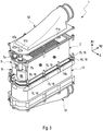
- FIG. 1 is an exploded illustration of the cooling device 1 of Figure 2 .
- the cooling device 1 comprises a heat exchanger, which in the example of the figures is configured as a tube-fin heat exchanger.
- the heat exchanger 2 or tube-fin heat exchanger has a plurality of gas paths 3 extending along a first direction R1 and a plurality of coolant paths 4 extending along a second direction R2.
- the gas paths 3 and the coolant paths 4 can be stacked on one another along a stacking direction S, which runs perpendicular both to the first direction R1 and to the second direction R2. Heat is withdrawn from the gas to be cooled and fed to the coolant by heat exchange between the gas and the coolant, as a result of which the desired cooling of the gas is achieved.
- a coolant distributor 5 is provided on the heat exchanger 2.
- the coolant distributor 5 comprises a first container 6a, which is mounted laterally with respect to the stacking direction S on the heat exchanger 2 and from which there protrudes upwards a first tubular body 7a fastened to the first container 6a.
- the first tubular body 7a By way of the first tubular body 7a, the coolant can be fed into the first container 6a and distributed therefrom over the individual coolant paths 4.
- the first container 6a communicates with the coolant paths 4 of the heat exchanger 2.
- the two containers 6a, 6b are fastened to a side wall 21 of the heat exchanger 2.
- a coolant collector 8 which likewise communicates with the coolant paths 4 is provided on the heat exchanger 2.
- the coolant collector 8 comprises a second container 6b, which is mounted beneath the first container 6a and adjacent thereto on the heat exchanger 2.
- a second tubular body 7b fastened to the second container 6b protrudes upwards from the second container 6b.
- the two tubular bodies 7a, 7b both extend each along the first direction R1.
- the two tubular bodies 7a, 7b thus extend parallel to one another.
- the second tubular body 7b can be soldered to the first container 6a at least in certain portions.
- the two containers 6a, 6b are in this case arranged and fastened one above the other on the same side of the heat exchanger 2 on the housing wall 21.
- the coolant distributor 5 and the coolant collector 8 can be interchanged.
- the terms “top”, “bottom”, “above” and “beneath” used above and hereinbelow preferably refer to a mounting position or to a position of use of the cooling device 1 in a motor vehicle.
- the first tubular body 7a has a first mouth opening 9a and the second tubular body 7b has a second mouth opening 9b.
- the first container 6a is arranged between the second container 6b and the two mouth openings 9a, 9b with respect to the first direction R1.
- the first tubular body 7a and the first container 6a have a two-part form.
- the first tubular body 7a is insertable along the first direction R1 into a first container opening 10a present on the first container 6a.
- the second tubular body and the second container have a two-part form.
- the second tubular body 7b is insertable along the first direction R1 into a second container opening 10b present on the second container 6b.
- the second tubular body 7b can also have a multi-part form - in the example of Figure 2 , a two-part form is shown by way of example - with a first tubular piece 20a and a second tubular piece 20b adjoining the latter in the first direction R1.
- a multi-part form of this type is analogously also possible in the case of the first tubular body 7a.
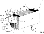
- FIGs 3 and 4 show a development of the cooling device 1 of Figures 1 and 2 .
- Figure 3 shows an exploded illustration of the cooling device 1 of Figure 4 .
- a gas distributor 12 and a gas collector 13 are fastened detachably to the heat exchanger 2 on two sides 11 a, 11 b of the heat exchanger 2 which lie opposite one another along the first direction R1.
- the gas distributor 12 and the gas collector 13 each communicate with the individual gas paths 3, in order to distribute the gas to be cooled over the individual gas paths 3 of the heat exchanger 2a and to collect it again after it has flowed through the heat exchanger 2.
- the gas distributor 12 and the gas collector 13 are each in the form of a housing with a hood-like configuration and have an inlet opening and outlet opening, which are oriented along the second direction R2.
- Two apertures 17a, 17b, through which the first and the second tubular bodies 7a, 7b engage along the first direction R1, are formed on the gas distributor 12.
- the cooling device 1 comprises a housing 14, into which the heat exchanger 2 can be inserted together with the two containers 6a, 6b and the two tubular bodies 7a, 7b along the first direction R1.
- the gas distributor 12 and the gas collector 13 are fastened detachably to the housing 14 of the heat exchanger 2 by means of screw connections 15.
- the screw connections 15 comprise screw elements 16, which can be screwed along the first direction R1 into complementary receptacles 18 provided on the housing.
Priority Applications (1)
| Application Number | Priority Date | Filing Date | Title |
|---|---|---|---|
| EP16188772.4A EP3296536A1 (fr) | 2016-09-14 | 2016-09-14 | Dispositif de refroidissement, en particulier pour un véhicule automobile |
Applications Claiming Priority (1)
| Application Number | Priority Date | Filing Date | Title |
|---|---|---|---|
| EP16188772.4A EP3296536A1 (fr) | 2016-09-14 | 2016-09-14 | Dispositif de refroidissement, en particulier pour un véhicule automobile |
Publications (1)
| Publication Number | Publication Date |
|---|---|
| EP3296536A1 true EP3296536A1 (fr) | 2018-03-21 |
Family
ID=56958758
Family Applications (1)
| Application Number | Title | Priority Date | Filing Date |
|---|---|---|---|
| EP16188772.4A Withdrawn EP3296536A1 (fr) | 2016-09-14 | 2016-09-14 | Dispositif de refroidissement, en particulier pour un véhicule automobile |
Country Status (1)
| Country | Link |
|---|---|
| EP (1) | EP3296536A1 (fr) |
Cited By (1)
| Publication number | Priority date | Publication date | Assignee | Title |
|---|---|---|---|---|
| CN110295992A (zh) * | 2018-03-23 | 2019-10-01 | 翰昂汽车零部件有限公司 | 由液冷的预冷器和空冷的主冷器构成的增压空气冷却器 |
Citations (6)
| Publication number | Priority date | Publication date | Assignee | Title |
|---|---|---|---|---|
| US4474162A (en) * | 1983-03-01 | 1984-10-02 | The Garrett Corporation | Charge air cooler mounting arrangement |
| US6202741B1 (en) * | 1997-11-25 | 2001-03-20 | Behr Gmbh & Co. | Heat transfer device for a motor vehicle and method of making same |
| US6302196B1 (en) * | 1998-04-29 | 2001-10-16 | Valeo Klimatechnik Gmgh & Co., Kg | Heat exchanger as heat exchanger in heating installations or engine radiator of motor vehicles |
| WO2010146063A1 (fr) * | 2009-06-15 | 2010-12-23 | Behr Gmbh & Co. Kg | Collecteur d'admission à refroidisseur d'air de suralimentation intégré |
| WO2013092638A1 (fr) * | 2011-12-22 | 2013-06-27 | Valeo Systemes De Controle Moteur | Échangeur de chaleur à plaques empilées comprenant un collecteur |
| FR2991039A1 (fr) * | 2012-05-22 | 2013-11-29 | Valeo Systemes Thermiques | Echangeur de chaleur, notamment refroidisseur d'air de suralimentation de moteur de vehicule automobile |
-
2016
- 2016-09-14 EP EP16188772.4A patent/EP3296536A1/fr not_active Withdrawn
Patent Citations (6)
| Publication number | Priority date | Publication date | Assignee | Title |
|---|---|---|---|---|
| US4474162A (en) * | 1983-03-01 | 1984-10-02 | The Garrett Corporation | Charge air cooler mounting arrangement |
| US6202741B1 (en) * | 1997-11-25 | 2001-03-20 | Behr Gmbh & Co. | Heat transfer device for a motor vehicle and method of making same |
| US6302196B1 (en) * | 1998-04-29 | 2001-10-16 | Valeo Klimatechnik Gmgh & Co., Kg | Heat exchanger as heat exchanger in heating installations or engine radiator of motor vehicles |
| WO2010146063A1 (fr) * | 2009-06-15 | 2010-12-23 | Behr Gmbh & Co. Kg | Collecteur d'admission à refroidisseur d'air de suralimentation intégré |
| WO2013092638A1 (fr) * | 2011-12-22 | 2013-06-27 | Valeo Systemes De Controle Moteur | Échangeur de chaleur à plaques empilées comprenant un collecteur |
| FR2991039A1 (fr) * | 2012-05-22 | 2013-11-29 | Valeo Systemes Thermiques | Echangeur de chaleur, notamment refroidisseur d'air de suralimentation de moteur de vehicule automobile |
Cited By (1)
| Publication number | Priority date | Publication date | Assignee | Title |
|---|---|---|---|---|
| CN110295992A (zh) * | 2018-03-23 | 2019-10-01 | 翰昂汽车零部件有限公司 | 由液冷的预冷器和空冷的主冷器构成的增压空气冷却器 |
Similar Documents
| Publication | Publication Date | Title |
|---|---|---|
| US6666263B2 (en) | Device for cooling a vehicle appliance, in particular a battery or a fuel cell | |
| CN109312988B (zh) | 具有过冷功能的热交换器凸缘板 | |
| EP2945217A1 (fr) | Dispositif de refroidissement pour un bloc-batterie | |
| US8210247B2 (en) | Plate heat exchanger | |
| US20080041556A1 (en) | Stacked/bar plate charge air cooler including inlet and outlet tanks | |
| US7793710B2 (en) | Intercooler apparatus and method | |
| US8627880B2 (en) | Exhaust gas cooler | |
| US10260817B2 (en) | Stacked-plate heat exchanger | |
| US11563245B2 (en) | Arrangement for cooling of electrical energy storage units | |
| EP2944911B1 (fr) | Échangeur thermique | |
| US20140373798A1 (en) | Heat exchanger, in particular for a vehicle comprising a heat engine | |
| KR20150015463A (ko) | 열 교환기 모듈용 커버 | |
| US20140305621A1 (en) | Multiplate heat exchanger | |
| JP2006307759A (ja) | Egrクーラ装置 | |
| JP2019507053A (ja) | 自動車両空調設備の熱交換器用のタンクを充填するための充填チューブを有する相変化材料のタンク | |
| US20080245514A1 (en) | Charge Air Intercooler | |
| US20020023730A1 (en) | Compact heat exchanger for a compact cooling system | |
| KR102408712B1 (ko) | 차량용 쿨링모듈 | |
| EP3296536A1 (fr) | Dispositif de refroidissement, en particulier pour un véhicule automobile | |
| US10113807B2 (en) | Indirect-type air cooler | |
| US10024587B2 (en) | Evaporator heat exchanger unit | |
| US9016357B2 (en) | Header plate and heat exchanger comprising same | |
| US20150316299A1 (en) | Combined Intake and Exhaust Manifold for a Thermoelectric Temperature Control Device | |
| CN111979584B (zh) | 一种立式联苯炉 | |
| JP6194921B2 (ja) | エンジンの吸気冷却装置 |
Legal Events
| Date | Code | Title | Description |
|---|---|---|---|
| PUAI | Public reference made under article 153(3) epc to a published international application that has entered the european phase |
Free format text: ORIGINAL CODE: 0009012 |
|
| AK | Designated contracting states |
Kind code of ref document: A1 Designated state(s): AL AT BE BG CH CY CZ DE DK EE ES FI FR GB GR HR HU IE IS IT LI LT LU LV MC MK MT NL NO PL PT RO RS SE SI SK SM TR |
|
| AX | Request for extension of the european patent |
Extension state: BA ME |
|
| 17P | Request for examination filed |
Effective date: 20180921 |
|
| RBV | Designated contracting states (corrected) |
Designated state(s): AL AT BE BG CH CY CZ DE DK EE ES FI FR GB GR HR HU IE IS IT LI LT LU LV MC MK MT NL NO PL PT RO RS SE SI SK SM TR |
|
| GRAP | Despatch of communication of intention to grant a patent |
Free format text: ORIGINAL CODE: EPIDOSNIGR1 |
|
| INTG | Intention to grant announced |
Effective date: 20181126 |
|
| STAA | Information on the status of an ep patent application or granted ep patent |
Free format text: STATUS: THE APPLICATION IS DEEMED TO BE WITHDRAWN |
|
| 18D | Application deemed to be withdrawn |
Effective date: 20190409 |