EP3296461A1 - Ensemble à câble - Google Patents
Ensemble à câble Download PDFInfo
- Publication number
- EP3296461A1 EP3296461A1 EP17189548.5A EP17189548A EP3296461A1 EP 3296461 A1 EP3296461 A1 EP 3296461A1 EP 17189548 A EP17189548 A EP 17189548A EP 3296461 A1 EP3296461 A1 EP 3296461A1
- Authority
- EP
- European Patent Office
- Prior art keywords
- tube
- cable
- cable management
- clip
- management assembly
- Prior art date
- Legal status (The legal status is an assumption and is not a legal conclusion. Google has not performed a legal analysis and makes no representation as to the accuracy of the status listed.)
- Withdrawn
Links
- 238000003780 insertion Methods 0.000 claims abstract description 7
- 230000037431 insertion Effects 0.000 claims abstract description 7
- 230000000717 retained effect Effects 0.000 claims abstract description 6
- 230000000712 assembly Effects 0.000 claims description 13
- 238000000429 assembly Methods 0.000 claims description 13
- 239000012811 non-conductive material Substances 0.000 claims description 5
- 238000009434 installation Methods 0.000 description 6
- 241001669679 Eleotris Species 0.000 description 5
- 238000000034 method Methods 0.000 description 5
- 239000011152 fibreglass Substances 0.000 description 4
- 230000008901 benefit Effects 0.000 description 3
- 229920002302 Nylon 6,6 Polymers 0.000 description 2
- 239000004033 plastic Substances 0.000 description 2
- 229920003023 plastic Polymers 0.000 description 2
- 230000006978 adaptation Effects 0.000 description 1
- 230000001627 detrimental effect Effects 0.000 description 1
- 238000012423 maintenance Methods 0.000 description 1
- 239000000463 material Substances 0.000 description 1
Images


Classifications
-
- H—ELECTRICITY
- H02—GENERATION; CONVERSION OR DISTRIBUTION OF ELECTRIC POWER
- H02G—INSTALLATION OF ELECTRIC CABLES OR LINES, OR OF COMBINED OPTICAL AND ELECTRIC CABLES OR LINES
- H02G3/00—Installations of electric cables or lines or protective tubing therefor in or on buildings, equivalent structures or vehicles
- H02G3/26—Installations of cables, lines, or separate protective tubing therefor directly on or in walls, ceilings, or floors
- H02G3/263—Installation, e.g. suspension, of conduit channels or other supports
-
- E—FIXED CONSTRUCTIONS
- E01—CONSTRUCTION OF ROADS, RAILWAYS, OR BRIDGES
- E01B—PERMANENT WAY; PERMANENT-WAY TOOLS; MACHINES FOR MAKING RAILWAYS OF ALL KINDS
- E01B26/00—Tracks or track components not covered by any one of the preceding groups
-
- F—MECHANICAL ENGINEERING; LIGHTING; HEATING; WEAPONS; BLASTING
- F16—ENGINEERING ELEMENTS AND UNITS; GENERAL MEASURES FOR PRODUCING AND MAINTAINING EFFECTIVE FUNCTIONING OF MACHINES OR INSTALLATIONS; THERMAL INSULATION IN GENERAL
- F16L—PIPES; JOINTS OR FITTINGS FOR PIPES; SUPPORTS FOR PIPES, CABLES OR PROTECTIVE TUBING; MEANS FOR THERMAL INSULATION IN GENERAL
- F16L3/00—Supports for pipes, cables or protective tubing, e.g. hangers, holders, clamps, cleats, clips, brackets
- F16L3/08—Supports for pipes, cables or protective tubing, e.g. hangers, holders, clamps, cleats, clips, brackets substantially surrounding the pipe, cable or protective tubing
- F16L3/12—Supports for pipes, cables or protective tubing, e.g. hangers, holders, clamps, cleats, clips, brackets substantially surrounding the pipe, cable or protective tubing comprising a member substantially surrounding the pipe, cable or protective tubing
-
- F—MECHANICAL ENGINEERING; LIGHTING; HEATING; WEAPONS; BLASTING
- F16—ENGINEERING ELEMENTS AND UNITS; GENERAL MEASURES FOR PRODUCING AND MAINTAINING EFFECTIVE FUNCTIONING OF MACHINES OR INSTALLATIONS; THERMAL INSULATION IN GENERAL
- F16L—PIPES; JOINTS OR FITTINGS FOR PIPES; SUPPORTS FOR PIPES, CABLES OR PROTECTIVE TUBING; MEANS FOR THERMAL INSULATION IN GENERAL
- F16L3/00—Supports for pipes, cables or protective tubing, e.g. hangers, holders, clamps, cleats, clips, brackets
- F16L3/08—Supports for pipes, cables or protective tubing, e.g. hangers, holders, clamps, cleats, clips, brackets substantially surrounding the pipe, cable or protective tubing
- F16L3/10—Supports for pipes, cables or protective tubing, e.g. hangers, holders, clamps, cleats, clips, brackets substantially surrounding the pipe, cable or protective tubing divided, i.e. with two or more members engaging the pipe, cable or protective tubing
-
- F—MECHANICAL ENGINEERING; LIGHTING; HEATING; WEAPONS; BLASTING
- F16—ENGINEERING ELEMENTS AND UNITS; GENERAL MEASURES FOR PRODUCING AND MAINTAINING EFFECTIVE FUNCTIONING OF MACHINES OR INSTALLATIONS; THERMAL INSULATION IN GENERAL
- F16L—PIPES; JOINTS OR FITTINGS FOR PIPES; SUPPORTS FOR PIPES, CABLES OR PROTECTIVE TUBING; MEANS FOR THERMAL INSULATION IN GENERAL
- F16L3/00—Supports for pipes, cables or protective tubing, e.g. hangers, holders, clamps, cleats, clips, brackets
- F16L3/08—Supports for pipes, cables or protective tubing, e.g. hangers, holders, clamps, cleats, clips, brackets substantially surrounding the pipe, cable or protective tubing
- F16L3/12—Supports for pipes, cables or protective tubing, e.g. hangers, holders, clamps, cleats, clips, brackets substantially surrounding the pipe, cable or protective tubing comprising a member substantially surrounding the pipe, cable or protective tubing
- F16L3/1215—Supports for pipes, cables or protective tubing, e.g. hangers, holders, clamps, cleats, clips, brackets substantially surrounding the pipe, cable or protective tubing comprising a member substantially surrounding the pipe, cable or protective tubing the pipe being fixed by rotation of an element
-
- F—MECHANICAL ENGINEERING; LIGHTING; HEATING; WEAPONS; BLASTING
- F16—ENGINEERING ELEMENTS AND UNITS; GENERAL MEASURES FOR PRODUCING AND MAINTAINING EFFECTIVE FUNCTIONING OF MACHINES OR INSTALLATIONS; THERMAL INSULATION IN GENERAL
- F16L—PIPES; JOINTS OR FITTINGS FOR PIPES; SUPPORTS FOR PIPES, CABLES OR PROTECTIVE TUBING; MEANS FOR THERMAL INSULATION IN GENERAL
- F16L3/00—Supports for pipes, cables or protective tubing, e.g. hangers, holders, clamps, cleats, clips, brackets
- F16L3/26—Supports for pipes, cables or protective tubing, e.g. hangers, holders, clamps, cleats, clips, brackets specially adapted for supporting the pipes all along their length, e.g. pipe channels or ducts
-
- H—ELECTRICITY
- H02—GENERATION; CONVERSION OR DISTRIBUTION OF ELECTRIC POWER
- H02G—INSTALLATION OF ELECTRIC CABLES OR LINES, OR OF COMBINED OPTICAL AND ELECTRIC CABLES OR LINES
- H02G3/00—Installations of electric cables or lines or protective tubing therefor in or on buildings, equivalent structures or vehicles
- H02G3/02—Details
- H02G3/04—Protective tubing or conduits, e.g. cable ladders or cable troughs
-
- H—ELECTRICITY
- H02—GENERATION; CONVERSION OR DISTRIBUTION OF ELECTRIC POWER
- H02G—INSTALLATION OF ELECTRIC CABLES OR LINES, OR OF COMBINED OPTICAL AND ELECTRIC CABLES OR LINES
- H02G3/00—Installations of electric cables or lines or protective tubing therefor in or on buildings, equivalent structures or vehicles
- H02G3/30—Installations of cables or lines on walls, floors or ceilings
-
- F—MECHANICAL ENGINEERING; LIGHTING; HEATING; WEAPONS; BLASTING
- F16—ENGINEERING ELEMENTS AND UNITS; GENERAL MEASURES FOR PRODUCING AND MAINTAINING EFFECTIVE FUNCTIONING OF MACHINES OR INSTALLATIONS; THERMAL INSULATION IN GENERAL
- F16L—PIPES; JOINTS OR FITTINGS FOR PIPES; SUPPORTS FOR PIPES, CABLES OR PROTECTIVE TUBING; MEANS FOR THERMAL INSULATION IN GENERAL
- F16L3/00—Supports for pipes, cables or protective tubing, e.g. hangers, holders, clamps, cleats, clips, brackets
- F16L3/08—Supports for pipes, cables or protective tubing, e.g. hangers, holders, clamps, cleats, clips, brackets substantially surrounding the pipe, cable or protective tubing
- F16L3/12—Supports for pipes, cables or protective tubing, e.g. hangers, holders, clamps, cleats, clips, brackets substantially surrounding the pipe, cable or protective tubing comprising a member substantially surrounding the pipe, cable or protective tubing
- F16L3/13—Supports for pipes, cables or protective tubing, e.g. hangers, holders, clamps, cleats, clips, brackets substantially surrounding the pipe, cable or protective tubing comprising a member substantially surrounding the pipe, cable or protective tubing and engaging it by snap action
-
- H—ELECTRICITY
- H02—GENERATION; CONVERSION OR DISTRIBUTION OF ELECTRIC POWER
- H02G—INSTALLATION OF ELECTRIC CABLES OR LINES, OR OF COMBINED OPTICAL AND ELECTRIC CABLES OR LINES
- H02G3/00—Installations of electric cables or lines or protective tubing therefor in or on buildings, equivalent structures or vehicles
- H02G3/02—Details
- H02G3/04—Protective tubing or conduits, e.g. cable ladders or cable troughs
- H02G3/0437—Channels
-
- H—ELECTRICITY
- H02—GENERATION; CONVERSION OR DISTRIBUTION OF ELECTRIC POWER
- H02G—INSTALLATION OF ELECTRIC CABLES OR LINES, OR OF COMBINED OPTICAL AND ELECTRIC CABLES OR LINES
- H02G3/00—Installations of electric cables or lines or protective tubing therefor in or on buildings, equivalent structures or vehicles
- H02G3/30—Installations of cables or lines on walls, floors or ceilings
- H02G3/32—Installations of cables or lines on walls, floors or ceilings using mounting clamps
-
- H—ELECTRICITY
- H02—GENERATION; CONVERSION OR DISTRIBUTION OF ELECTRIC POWER
- H02G—INSTALLATION OF ELECTRIC CABLES OR LINES, OR OF COMBINED OPTICAL AND ELECTRIC CABLES OR LINES
- H02G9/00—Installations of electric cables or lines in or on the ground or water
- H02G9/04—Installations of electric cables or lines in or on the ground or water in surface ducts; Ducts or covers therefor
Definitions
- the field of the invention relates to a cable management assembly and in particular a cable management assembly for use with a railway rail.
- a common problem in the field of railway design and, in particular, railway rail cabling is how to appropriately manage or organise cables which need to be routed underneath the running rails of a train track.
- Existing methods of routing cables underneath running rails include clipping the cables to railway sleepers, which support the rails. This technique can be detrimental to the life of the sleepers depending on the methods used to clip the cables to the sleepers and can also take significant time for installation, which in turns raises cost and complexity.
- Another method for routing cables underneath railway tracks includes laying simple plastic drainpipes underneath the rails as a guide and running cables through the plastic drainpipes. It can however be impossible or very difficult to run cables with plug couplers (plug ends) through such drainpipes as they may be too large or a very tight fit. Also, as the drainpipes are not normally secured in place, the drainpipes do not restrict movement of the cables once laid. This method also requires that the cables are run through the ends of the drainpipes.
- a cable management assembly for use with a railway rail, the cable management assembly comprising: a connector comprising a clip and a fastener for fastening the clip to an underside of a foot of the railway rail, and a tube comprising, along the length of the tube, a slit for insertion of a cable into the tube, wherein the clip comprises an opening through which the tube is insertable into the clip, and the tube and clip are configured to be moveable relative to each other between an open position, in which the slit and opening are aligned to allow the cable to be inserted into the tube, and a closed position, in which the slit and opening are out of alignment so that the cable is retained in the tube.
- the cable management assembly may either be fitted to a single rail, such that a cable runs from outside the rail into the gap between that rail and an adjacent rail, or vice versa, or can be fitted to two adjacent rails, so that the cable runs from the outer side of one of the rails, through the gap between the rails, to the outer side of the other rail.
- the fastener may preferably be designed for rapid deployment, such as providing a "snap-fit" attachment to an underside of the foot of the railway.
- the slit along the length of the tube may preferably be large enough that at least a single cable can be inserted into the tube easily.
- the size of the tube and clip may be adapted to accommodate as many cables as is necessary for the given task.
- a cable management assembly provides for rapid installation requiring little or no change to the configuration of the assembly and having no moving parts other than the relative rotation of the tube to the clip, which rotation can be performed by the installer from either side of the railway rail (either end of the tube).
- the cable management assembly further comprises one or more removable cable retainers each for covering the slit at a point along the length of the tube to retain the cable in the tube.
- a removable cable retainer can be fitted in place either over the slit or around the tube to allow the cables to be retained in the tube.
- more than one removable cable retainer may be used. For example such a retainer may be attached at either end of the tube.
- a removable cable retainer may be provided to retain the one or more cables within the tube.
- a cable management assembly for use with a railway rail, the cable management assembly comprising: a connector comprising a receptacle and a fastener for fastening the receptacle to an underside of a foot of the railway rail, a tube comprising, along the length of the tube, a slit for insertion of a cable into the tube, and one or more removable cable retainers each for covering part of the slit at a point along the length of the tube to retain the cable in the tube, wherein the receptacle comprises an opening through which the tube is insertable into the receptacle.
- a cable management assembly embodying the first or second aspect of the present invention is made of a non-conductive material. It is desirable that the cable management assembly is non-conductive so that the cables are electrically isolated from the railway rail.
- suitable non-conductive materials include nylon 66, which may be used for the clip, and GRP (glass reinforced plastics) pultrusion for the tube.
- Materials of the respective parts of the cable management assembly may include other non-conductive materials, preferably with a high durability, such that once installed they require little or no maintenance for long periods of time and do not succumb to weather damage, whilst ensuring the railway rails remain electrically isolated.
- the slit extends along the entire length of the tube, since it is particularly easy to install cables into the tube if the cables can be inserted along the entire length of the tube. Once installed the cables enter and exit the tube through the ends of the tube rather than through the slit.
- the connector includes a second clip, comprising a second opening through which the tube is insertable into the second clip, the second clip being configured to be fastened to the underside of the foot of the railway rail by the fastener.
- each clip provides further hold on the tube to reduce or inhibit movement.
- the positioning of the tube as part of the cable management assembly can be improved and movement reduced through inclusion of the second clip to hold the tube in place. This is particularly advantageous if rotational motion is undesirable as a second clip would provide greater resistance to forces encouraging such motion.
- the clip or clips may be used to position the removable cable retainer.
- the removable cable retainer may preferably be positioned between the two clips.
- a plurality of cable management assemblies forms a system for passing cables under a plurality of railway rails.
- the system comprises a plurality of cable management assemblies as described above, wherein each cable management assembly is attached to one railway rail of the plurality of railway rails.
- the tubes of the cable management assemblies may comprise a single tube which extends through the clips or receptacles of all of the cable management assemblies in the system.
- Embodiments of the invention provide a cable management assembly for the purpose of managing cables which are to be run from one side of one or more railway rails (rails) to the other side. More specifically, the embodiments relate to a way of passing cables under one or more railway rails safely.
- Figure 1 shows a cable management assembly 2 according to an exemplary embodiment of the first aspect of the present invention.
- the cable management assembly 2 includes a connector 10.
- the connector 10 includes a fastener 11, which fastener 11 is configured to fasten around an underside 1a of a foot 1b of a railway rail 1.
- the rail 1 extends from the top left of the figure with the foot 1b passing through the fastener 11 of the cable management assembly 2, and the rail 1 is then obscured behind the cable management assembly 2 on the right of the Figure.
- the cable management assembly 2 further includes a tube 20.
- the connector 10 further includes a clip 12.
- the clip 12 is configured to clip around the tube 20.
- the fastener 11 includes a first side portion 11a and a second side portion 11b, which side portions extend around either side of the foot 1b of the railway rail 1, so as to fasten the clip 12 (and/or the connector 10 as a whole) to the rail 1.
- the side portions 11a, 11b may attach around the foot 1b of the rail 1 in a snap-fit manner. This type of fastening helps to inhibit relative movement between the connector 10 and the rail 1.
- the first and second side portions 11a, 11b of the fastener 11 are connected by a connecting portion 11c. When fitted to a rail 1, the connecting portion 11c of the fastener 11 extends adjacent to, and in parallel with, the underside 1a of the rail 1. To provide additional structural support, the connecting portion 11c may be corrugated or be otherwise reinforced.
- the clip 12 is provided on a side of the connector 10 opposite the fastener 11, as shown in Figure 1 .
- the clip 12 may be positioned at any point along the connecting portion 11c of the fastener 11.
- Figure 1 shows an exemplary embodiment in which the clip 12 is attached to the connecting portion 11c of the fastener 11 at a position close to the first side portion 11a. The embodiment is however not limited to this position.
- the clip 12 is configured to extend away from the fastener 11 to hold the tube 20 in a position such that the tube 20 passes below the railway rail 1.
- the tube 20 is an open tube (i.e. it is open at both ends) and includes a slit 20a which extends along the tube in the axial direction of the tube.
- the slit 20a may, as shown, extend along the full length of the tube 20.
- the slit 20a is configured to allow one or more cables to be inserted into, or removed from, the tube 20.
- the tube 20 may optionally be a rigid tube meaning that the slit 20a remains open without any additional force being applied to the tube 20.
- the tube may be a flexible tube wherein the slit 20a remains substantially closed until an opening force is applied to the tube 20 to open the slit 20a for insertion or removal of a cable.
- the clip 12 may preferably be a flexible clip configured to move with the flexible tube 20 so as to maintain a firm hold on the tube 20 when the slit 20a is open or closed.
- the fastener 11 is attached to the underside 1a of the railway rail 1 and the tube 20 is inserted into the clip 12.
- the slit 20a in the tube 20 is, in one configuration, arranged to be aligned with an opening 12a in the clip 12.
- This arrangement is shown in Figure 1 .
- the alignment of the slit 20a and the opening 12a allows one or more cables to be inserted into the tube 20 or removed from the tube 20.
- the tube 20 may be rotated relative to the clip 12 so that the slit 20a is no longer aligned with the opening 12a.
- This arrangement is shown in Figure 2 .
- the arrangement shown in Figure 1 may be described as an unlocked or open position.
- the arrangement shown in Figure 2 may be described as a locked or closed position.
- the slit 20a and the opening 12a need only be sufficiently aligned to allow one or more cables to be inserted into or removed from the tube 20.
- the tube 20 may include a ridge or lip 20b which extends slightly outwards from the edges of the tube 20 either side of the slit 20a, to aid positioning and alignment of the slit 20a with the opening 12a.
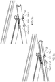
- the connector 10 may include two or more clips 12. As shown in Figures 3a and 3b , in one arrangement the connector 10 includes two clips 12-1, 12-2. Reference sign "12" will be used when no particular clip is being referred to. Figure 3a shows this arrangement in the unlocked position, in which the slit 20a is aligned with the openings 12a-1, 12a-2 of both clips 12-1, 12-2. Both clips 12-1, 12-2 have approximately the same configuration and may be positioned next to and in parallel with each other such that the tube 20 when positioned in the unlocked position provides the slit 20a to be aligned with both openings 12a-1, 12a-2. This arrangement is shown in Figure 3a .
- the clips 12-1, 12-2 are positioned near opposing ends (near the first side portion 11a and the second side portion 11b, respectively) to provide greater resistance to movement of the tube 20 thus ensuring that the positioning of the cables, once installed, remains unchanged.
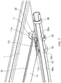
- Figures 4a and 4b show side-on views of an embodiment of the invention in the unlocked position, with the slit 20a and opening 12a aligned, and in the locked position, with the slit 20a and opening 12a not in alignment, respectively.
- FIGs 5a and 5b show unlocked and locked arrangements of an embodiment of the invention, respectively.
- the cable management assembly 2 is attached to one of two parallel railway rails 1 and the tube 20 extends from an outer side of one of the rails, under that rail 1 to the gap between the two rails 1.
- FIGS 6a and 6b show an alternative embodiment in which two cable management assemblies 2 are attached to respective parallel rails 1.
- the tubes 20 of the cable management assemblies 2 comprise a single tube, which extends between the cable management assemblies 2 and through the clips 12 of both cable management assemblies 2.
- each cable management assembly 2 may include a separate tube 20.
- providing a single tube 20 extending between the two cable management assemblies 2 has the benefit that in both cable management assemblies 2 the slit 20a and opening 12a will be aligned simultaneously.
- a cable management assembly 2 includes a removable cable retainer 50, as shown in Figure 7 .
- a connector 30 includes a receptacle 32, with the receptacle 32 containing an opening 32a.
- a tube 40 is received into the receptacle 32 through the opening 32a.
- the fastener 11 and railway rail 1 of this embodiment corresponds to those of the earlier embodiments.
- the receptacle 32 receives the tube 40 and holds the tube 40 in a position corresponding to the open position of the earlier embodiments.
- This embodiment differs from the earlier embodiments as there is no need for relative movement or rotation between the receptacle 32 and tube 40 to move to a closed position.
- cables are retained in the tube 40 by means of the removable cable retainer 50, which may be positioned at any point on the length of the tube 40.
- this embodiment is not limited to a single removable cable retainer 50 and multiple removable cable retainers 50 may be used to improve the resistance to cables accidentally being pulled out of the tube 40.
- Figure 7 includes two receptacles 32. However, this embodiment is not limited to two receptacles 32. A single receptacle 32 or more than two are also envisaged.
- the cable management assembly 2 may be positioned to attach to the underside 1a of a foot of the railway rail 1 adjacent to a railway sleeper, supporting the railway rail 1, such that the tube 20, 40 extends in parallel with the sleeper. Positioning the cable management assembly 2 adjacent to a sleeper provides the benefit that the cables extending to the tube 20, 40 will have extra protection from damage.
- the removable cable retainer 50 may for example be a C-shaped clip retainer which may be fitted either around the tube 40 or simply over the slit 40a.
- the removable cable retainer 50 may be of any configuration suitable for covering the slit 40a in the tube 40.
- the removable cable retainer 50 may alternatively be a tie (such as a cable tie).
- the cable management assembly 2 is preferably made of non-conductive materials, preferably with a high durability.
- nylon 66 may be used for the clip 12 or receptacle 32 and a GRP (glass reinforced plastics) pultrusion may be used for the tube 20, 40.
- GRP glass reinforced plastics
- the connecting portion 11c of the fastener 11 is adjustable to adjust the distance between the side portions 11a, 11b.
- the connecting portion 11c provides a ratcheting connection between the side portions 11a, 11b so that the fastener may be adjusted to any railway rail foot 1b size.
Landscapes
- Engineering & Computer Science (AREA)
- General Engineering & Computer Science (AREA)
- Mechanical Engineering (AREA)
- Architecture (AREA)
- Civil Engineering (AREA)
- Structural Engineering (AREA)
- Installation Of Indoor Wiring (AREA)
- Clamps And Clips (AREA)
Applications Claiming Priority (1)
| Application Number | Priority Date | Filing Date | Title |
|---|---|---|---|
| GB1615637.4A GB2554073B (en) | 2016-09-14 | 2016-09-14 | Cable management assembly |
Publications (1)
| Publication Number | Publication Date |
|---|---|
| EP3296461A1 true EP3296461A1 (fr) | 2018-03-21 |
Family
ID=57234553
Family Applications (1)
| Application Number | Title | Priority Date | Filing Date |
|---|---|---|---|
| EP17189548.5A Withdrawn EP3296461A1 (fr) | 2016-09-14 | 2017-09-06 | Ensemble à câble |
Country Status (5)
| Country | Link |
|---|---|
| US (1) | US20180073201A1 (fr) |
| EP (1) | EP3296461A1 (fr) |
| AU (1) | AU2017225065A1 (fr) |
| BR (1) | BR102017019558A2 (fr) |
| GB (1) | GB2554073B (fr) |
Cited By (2)
| Publication number | Priority date | Publication date | Assignee | Title |
|---|---|---|---|---|
| US11401663B2 (en) | 2018-03-07 | 2022-08-02 | Multiclip Co. Ltd. | Rail cover |
| EP4135139A1 (fr) * | 2021-08-09 | 2023-02-15 | ABN GmbH | Porte-composant pour composants électromécaniques |
Families Citing this family (3)
| Publication number | Priority date | Publication date | Assignee | Title |
|---|---|---|---|---|
| WO2019050825A1 (fr) * | 2017-09-06 | 2019-03-14 | Hubbell Incorporated | Pinces de câble |
| JP7049193B2 (ja) * | 2018-06-20 | 2022-04-06 | 東日本旅客鉄道株式会社 | ケーブル防護カバー |
| NL1044181B1 (en) * | 2021-10-13 | 2023-05-11 | Kampa B V | Railway Fauna Passage |
Citations (6)
| Publication number | Priority date | Publication date | Assignee | Title |
|---|---|---|---|---|
| DE3447836A1 (de) * | 1984-12-29 | 1986-07-03 | Stahlwerke Peine-Salzgitter Ag, 3320 Salzgitter | Kabeltrog fuer gleisanlagen |
| EP0889567A2 (fr) * | 1997-07-02 | 1999-01-07 | OBO Bettermann GmbH & Co. KG. | Système d'installation de câble |
| DE19754062A1 (de) * | 1997-07-02 | 1999-06-10 | Bettermann Obo Gmbh & Co Kg | Kabelverlegesystem |
| DE19828083A1 (de) * | 1997-07-02 | 1999-12-30 | Bettermann Obo Gmbh & Co Kg | Kabelverlegesystem |
| EP1681391A1 (fr) * | 2004-12-27 | 2006-07-19 | Thomas & Betts International, Inc. | Dispositif de fixation de moyens de réchauffement d'un rail de chemin de fer |
| WO2013105014A2 (fr) * | 2012-01-10 | 2013-07-18 | Mertrac Infraco (Proprietary) Limited | Infrastructure à câble et système associé |
Family Cites Families (24)
| Publication number | Priority date | Publication date | Assignee | Title |
|---|---|---|---|---|
| US4826078A (en) * | 1987-11-13 | 1989-05-02 | Imo Delaval Inc. | Wire-to-track-base retainer clip and keeper |
| US5148981A (en) * | 1989-05-19 | 1992-09-22 | Erico International Corporation | Track circuit retainer clip |
| US5127577A (en) * | 1989-05-19 | 1992-07-07 | Erico International Corporation | Track circuit retainer clip |
| US5463189A (en) * | 1993-12-23 | 1995-10-31 | Deneke; Bernard F. | Installation clip device for electrical cables |
| US5803654A (en) * | 1995-10-30 | 1998-09-08 | Capro, Inc. | Control cable mounting system |
| US6073896A (en) * | 1998-09-09 | 2000-06-13 | Instruments Specialties Co., Inc. | Gasket arrangement having retention clip track and method of making a gasket arrangement and method for securing a gasket to a wall |
| US6367744B1 (en) * | 2000-04-07 | 2002-04-09 | Richard A. Ebersole | Pipe supporting apparatus |
| US6685144B1 (en) * | 2001-04-23 | 2004-02-03 | Patrick A. Wochnick | Pipe support apparatus |
| US7434770B2 (en) * | 2004-11-18 | 2008-10-14 | William R. Schmidt | Pipe, tubing and conduit support and retainer |
| US20080116324A1 (en) * | 2005-02-08 | 2008-05-22 | Volvo Trucks North America | Shaping Guide for Vehicular Mounted Tubing |
| US8020811B2 (en) * | 2005-07-07 | 2011-09-20 | Panduit Corp. | Cable bracket and strap assembly |
| CN101303119B (zh) * | 2007-05-11 | 2012-03-14 | 鸿富锦精密工业(深圳)有限公司 | 导光柱固定装置 |
| US20090045301A1 (en) * | 2007-08-13 | 2009-02-19 | C&S Manufacturing Corporation | Rail mount for flexible conduit |
| US20090140108A1 (en) * | 2007-12-03 | 2009-06-04 | International Engine Intellectual Property Company, Llc | Multiple tube clip |
| FR2943856B1 (fr) * | 2009-03-25 | 2011-07-22 | Labinal | Dispositif de support pour harnais electrique a la traversee d'une structure |
| GB201001002D0 (en) * | 2010-01-22 | 2010-03-10 | Airbus Operations Ltd | A bracket for attaching an electrical cable to a vehicle |
| CN101841080B (zh) * | 2010-02-02 | 2013-03-20 | 鸿富锦精密工业(深圳)有限公司 | 天线屏蔽装置及其天线夹 |
| US20120091289A1 (en) * | 2010-08-17 | 2012-04-19 | Tomlinson Wendy M | Wire and catheter retention device |
| FR2966651B1 (fr) * | 2010-10-21 | 2012-11-02 | Snecma | Dispositif d'entretoisement de harnais electriques dans une turbomachine |
| US9450130B2 (en) * | 2011-01-27 | 2016-09-20 | Sunpower Corporation | Frame-mounted wire management device |
| JP2012231558A (ja) * | 2011-04-25 | 2012-11-22 | Sumitomo Wiring Syst Ltd | クリップ及びクリップ付ワイヤハーネス |
| US20120292460A1 (en) * | 2011-05-19 | 2012-11-22 | Wanho T Manufacturing Co., Ltd. | Organizing device for cable and wire |
| US8613411B1 (en) * | 2011-09-14 | 2013-12-24 | C & B Manufacturing | Retainer device |
| US9548598B2 (en) * | 2014-07-24 | 2017-01-17 | Cooper Technologies Company | Cable management fitting |
-
2016
- 2016-09-14 GB GB1615637.4A patent/GB2554073B/en not_active Expired - Fee Related
-
2017
- 2017-09-06 EP EP17189548.5A patent/EP3296461A1/fr not_active Withdrawn
- 2017-09-07 AU AU2017225065A patent/AU2017225065A1/en not_active Abandoned
- 2017-09-13 BR BR102017019558-9A patent/BR102017019558A2/pt not_active Application Discontinuation
- 2017-09-13 US US15/702,911 patent/US20180073201A1/en not_active Abandoned
Patent Citations (6)
| Publication number | Priority date | Publication date | Assignee | Title |
|---|---|---|---|---|
| DE3447836A1 (de) * | 1984-12-29 | 1986-07-03 | Stahlwerke Peine-Salzgitter Ag, 3320 Salzgitter | Kabeltrog fuer gleisanlagen |
| EP0889567A2 (fr) * | 1997-07-02 | 1999-01-07 | OBO Bettermann GmbH & Co. KG. | Système d'installation de câble |
| DE19754062A1 (de) * | 1997-07-02 | 1999-06-10 | Bettermann Obo Gmbh & Co Kg | Kabelverlegesystem |
| DE19828083A1 (de) * | 1997-07-02 | 1999-12-30 | Bettermann Obo Gmbh & Co Kg | Kabelverlegesystem |
| EP1681391A1 (fr) * | 2004-12-27 | 2006-07-19 | Thomas & Betts International, Inc. | Dispositif de fixation de moyens de réchauffement d'un rail de chemin de fer |
| WO2013105014A2 (fr) * | 2012-01-10 | 2013-07-18 | Mertrac Infraco (Proprietary) Limited | Infrastructure à câble et système associé |
Cited By (2)
| Publication number | Priority date | Publication date | Assignee | Title |
|---|---|---|---|---|
| US11401663B2 (en) | 2018-03-07 | 2022-08-02 | Multiclip Co. Ltd. | Rail cover |
| EP4135139A1 (fr) * | 2021-08-09 | 2023-02-15 | ABN GmbH | Porte-composant pour composants électromécaniques |
Also Published As
| Publication number | Publication date |
|---|---|
| GB2554073B (en) | 2019-10-02 |
| GB201615637D0 (en) | 2016-10-26 |
| BR102017019558A2 (pt) | 2018-05-02 |
| AU2017225065A1 (en) | 2018-03-29 |
| US20180073201A1 (en) | 2018-03-15 |
| GB2554073A (en) | 2018-03-28 |
Similar Documents
| Publication | Publication Date | Title |
|---|---|---|
| EP3296461A1 (fr) | Ensemble à câble | |
| US8042237B2 (en) | Cable routing clip | |
| AU2007253167B8 (en) | Separation and/or reinforcement device for a wire cable duct | |
| US7362941B2 (en) | Cable management system | |
| US8540090B2 (en) | Telescoping wire cable tray system | |
| EP2876048B1 (fr) | Capot de rails de siège télescopique | |
| RU2479902C2 (ru) | Фиксирующее устройство для проволочной трассы кабеля | |
| US9156554B2 (en) | System component module and method for mounting in an aircraft cabin | |
| RU2608564C2 (ru) | Опорное и фиксирующее устройство для проводов и кабелей | |
| US6843181B2 (en) | Ducting associated with rail track and installing apparatus | |
| CN109414113A (zh) | 用于安装抽屉元件的方法和用于可移动地安装抽屉元件、家具和家用电器的构造套件 | |
| RU2617383C2 (ru) | Сборное устройство | |
| DE102007017853B4 (de) | Mobile Trennwand für ein Luftfahrzeug | |
| EP3688357B1 (fr) | Attaches de câble | |
| US20090212173A1 (en) | Cable management device | |
| US20210226429A1 (en) | Cable Management Device | |
| KR102103424B1 (ko) | 설치가 용이한 분전함 유닛 | |
| EP3536854A1 (fr) | Couvercle de rail | |
| DE202013003686U1 (de) | Schienenfuß-Klammervorrichtung | |
| EP4312362A1 (fr) | Unité de montage pour panneaux solaires | |
| CN201541096U (zh) | 布线组件和交通运输设备 | |
| DE19727148C2 (de) | Befestigungselement für ein Datenkabel |
Legal Events
| Date | Code | Title | Description |
|---|---|---|---|
| PUAI | Public reference made under article 153(3) epc to a published international application that has entered the european phase |
Free format text: ORIGINAL CODE: 0009012 |
|
| STAA | Information on the status of an ep patent application or granted ep patent |
Free format text: STATUS: THE APPLICATION HAS BEEN PUBLISHED |
|
| AK | Designated contracting states |
Kind code of ref document: A1 Designated state(s): AL AT BE BG CH CY CZ DE DK EE ES FI FR GB GR HR HU IE IS IT LI LT LU LV MC MK MT NL NO PL PT RO RS SE SI SK SM TR |
|
| AX | Request for extension of the european patent |
Extension state: BA ME |
|
| STAA | Information on the status of an ep patent application or granted ep patent |
Free format text: STATUS: REQUEST FOR EXAMINATION WAS MADE |
|
| 17P | Request for examination filed |
Effective date: 20180921 |
|
| RBV | Designated contracting states (corrected) |
Designated state(s): AL AT BE BG CH CY CZ DE DK EE ES FI FR GB GR HR HU IE IS IT LI LT LU LV MC MK MT NL NO PL PT RO RS SE SI SK SM TR |
|
| STAA | Information on the status of an ep patent application or granted ep patent |
Free format text: STATUS: EXAMINATION IS IN PROGRESS |
|
| 17Q | First examination report despatched |
Effective date: 20190314 |
|
| RAP1 | Party data changed (applicant data changed or rights of an application transferred) |
Owner name: PANDROL (VORTOK) LIMITED |
|
| RIC1 | Information provided on ipc code assigned before grant |
Ipc: F16L 3/12 20060101ALI20191119BHEP Ipc: H02G 3/04 20060101ALN20191119BHEP Ipc: E01B 26/00 20060101AFI20191119BHEP Ipc: H02G 3/00 20060101ALI20191119BHEP Ipc: H02G 9/04 20060101ALN20191119BHEP Ipc: H02G 3/32 20060101ALN20191119BHEP Ipc: F16L 3/13 20060101ALN20191119BHEP |
|
| GRAP | Despatch of communication of intention to grant a patent |
Free format text: ORIGINAL CODE: EPIDOSNIGR1 |
|
| STAA | Information on the status of an ep patent application or granted ep patent |
Free format text: STATUS: GRANT OF PATENT IS INTENDED |
|
| INTG | Intention to grant announced |
Effective date: 20200121 |
|
| STAA | Information on the status of an ep patent application or granted ep patent |
Free format text: STATUS: THE APPLICATION IS DEEMED TO BE WITHDRAWN |
|
| 18D | Application deemed to be withdrawn |
Effective date: 20200603 |