EP3296080B1 - Vorrichtung zur herstellung dreidimensionaler objekte - Google Patents
Vorrichtung zur herstellung dreidimensionaler objekte Download PDFInfo
- Publication number
- EP3296080B1 EP3296080B1 EP17174400.6A EP17174400A EP3296080B1 EP 3296080 B1 EP3296080 B1 EP 3296080B1 EP 17174400 A EP17174400 A EP 17174400A EP 3296080 B1 EP3296080 B1 EP 3296080B1
- Authority
- EP
- European Patent Office
- Prior art keywords
- protective pane
- building material
- camera
- unit
- radiation
- Prior art date
- Legal status (The legal status is an assumption and is not a legal conclusion. Google has not performed a legal analysis and makes no representation as to the accuracy of the status listed.)
- Active
Links
Images

Classifications
-
- B—PERFORMING OPERATIONS; TRANSPORTING
- B29—WORKING OF PLASTICS; WORKING OF SUBSTANCES IN A PLASTIC STATE IN GENERAL
- B29C—SHAPING OR JOINING OF PLASTICS; SHAPING OF MATERIAL IN A PLASTIC STATE, NOT OTHERWISE PROVIDED FOR; AFTER-TREATMENT OF THE SHAPED PRODUCTS, e.g. REPAIRING
- B29C64/00—Additive manufacturing, i.e. manufacturing of three-dimensional [3D] objects by additive deposition, additive agglomeration or additive layering, e.g. by 3D printing, stereolithography or selective laser sintering
- B29C64/10—Processes of additive manufacturing
- B29C64/141—Processes of additive manufacturing using only solid materials
- B29C64/153—Processes of additive manufacturing using only solid materials using layers of powder being selectively joined, e.g. by selective laser sintering or melting
-
- B—PERFORMING OPERATIONS; TRANSPORTING
- B22—CASTING; POWDER METALLURGY
- B22F—WORKING METALLIC POWDER; MANUFACTURE OF ARTICLES FROM METALLIC POWDER; MAKING METALLIC POWDER; APPARATUS OR DEVICES SPECIALLY ADAPTED FOR METALLIC POWDER
- B22F10/00—Additive manufacturing of workpieces or articles from metallic powder
-
- B—PERFORMING OPERATIONS; TRANSPORTING
- B22—CASTING; POWDER METALLURGY
- B22F—WORKING METALLIC POWDER; MANUFACTURE OF ARTICLES FROM METALLIC POWDER; MAKING METALLIC POWDER; APPARATUS OR DEVICES SPECIALLY ADAPTED FOR METALLIC POWDER
- B22F10/00—Additive manufacturing of workpieces or articles from metallic powder
- B22F10/20—Direct sintering or melting
- B22F10/28—Powder bed fusion, e.g. selective laser melting [SLM] or electron beam melting [EBM]
-
- B—PERFORMING OPERATIONS; TRANSPORTING
- B22—CASTING; POWDER METALLURGY
- B22F—WORKING METALLIC POWDER; MANUFACTURE OF ARTICLES FROM METALLIC POWDER; MAKING METALLIC POWDER; APPARATUS OR DEVICES SPECIALLY ADAPTED FOR METALLIC POWDER
- B22F12/00—Apparatus or devices specially adapted for additive manufacturing; Auxiliary means for additive manufacturing; Combinations of additive manufacturing apparatus or devices with other processing apparatus or devices
- B22F12/60—Planarisation devices; Compression devices
- B22F12/67—Blades
-
- B—PERFORMING OPERATIONS; TRANSPORTING
- B22—CASTING; POWDER METALLURGY
- B22F—WORKING METALLIC POWDER; MANUFACTURE OF ARTICLES FROM METALLIC POWDER; MAKING METALLIC POWDER; APPARATUS OR DEVICES SPECIALLY ADAPTED FOR METALLIC POWDER
- B22F12/00—Apparatus or devices specially adapted for additive manufacturing; Auxiliary means for additive manufacturing; Combinations of additive manufacturing apparatus or devices with other processing apparatus or devices
- B22F12/90—Means for process control, e.g. cameras or sensors
-
- B—PERFORMING OPERATIONS; TRANSPORTING
- B22—CASTING; POWDER METALLURGY
- B22F—WORKING METALLIC POWDER; MANUFACTURE OF ARTICLES FROM METALLIC POWDER; MAKING METALLIC POWDER; APPARATUS OR DEVICES SPECIALLY ADAPTED FOR METALLIC POWDER
- B22F3/00—Manufacture of workpieces or articles from metallic powder characterised by the manner of compacting or sintering; Apparatus specially adapted therefor ; Presses and furnaces
- B22F3/003—Apparatus, e.g. furnaces
-
- B—PERFORMING OPERATIONS; TRANSPORTING
- B29—WORKING OF PLASTICS; WORKING OF SUBSTANCES IN A PLASTIC STATE IN GENERAL
- B29C—SHAPING OR JOINING OF PLASTICS; SHAPING OF MATERIAL IN A PLASTIC STATE, NOT OTHERWISE PROVIDED FOR; AFTER-TREATMENT OF THE SHAPED PRODUCTS, e.g. REPAIRING
- B29C64/00—Additive manufacturing, i.e. manufacturing of three-dimensional [3D] objects by additive deposition, additive agglomeration or additive layering, e.g. by 3D printing, stereolithography or selective laser sintering
- B29C64/30—Auxiliary operations or equipment
- B29C64/35—Cleaning
-
- B—PERFORMING OPERATIONS; TRANSPORTING
- B33—ADDITIVE MANUFACTURING TECHNOLOGY
- B33Y—ADDITIVE MANUFACTURING, i.e. MANUFACTURING OF THREE-DIMENSIONAL [3D] OBJECTS BY ADDITIVE DEPOSITION, ADDITIVE AGGLOMERATION OR ADDITIVE LAYERING, e.g. BY 3D PRINTING, STEREOLITHOGRAPHY OR SELECTIVE LASER SINTERING
- B33Y30/00—Apparatus for additive manufacturing; Details thereof or accessories therefor
-
- B—PERFORMING OPERATIONS; TRANSPORTING
- B33—ADDITIVE MANUFACTURING TECHNOLOGY
- B33Y—ADDITIVE MANUFACTURING, i.e. MANUFACTURING OF THREE-DIMENSIONAL [3D] OBJECTS BY ADDITIVE DEPOSITION, ADDITIVE AGGLOMERATION OR ADDITIVE LAYERING, e.g. BY 3D PRINTING, STEREOLITHOGRAPHY OR SELECTIVE LASER SINTERING
- B33Y40/00—Auxiliary operations or equipment, e.g. for material handling
-
- B—PERFORMING OPERATIONS; TRANSPORTING
- B33—ADDITIVE MANUFACTURING TECHNOLOGY
- B33Y—ADDITIVE MANUFACTURING, i.e. MANUFACTURING OF THREE-DIMENSIONAL [3D] OBJECTS BY ADDITIVE DEPOSITION, ADDITIVE AGGLOMERATION OR ADDITIVE LAYERING, e.g. BY 3D PRINTING, STEREOLITHOGRAPHY OR SELECTIVE LASER SINTERING
- B33Y50/00—Data acquisition or data processing for additive manufacturing
-
- B—PERFORMING OPERATIONS; TRANSPORTING
- B22—CASTING; POWDER METALLURGY
- B22F—WORKING METALLIC POWDER; MANUFACTURE OF ARTICLES FROM METALLIC POWDER; MAKING METALLIC POWDER; APPARATUS OR DEVICES SPECIALLY ADAPTED FOR METALLIC POWDER
- B22F10/00—Additive manufacturing of workpieces or articles from metallic powder
- B22F10/30—Process control
-
- B—PERFORMING OPERATIONS; TRANSPORTING
- B22—CASTING; POWDER METALLURGY
- B22F—WORKING METALLIC POWDER; MANUFACTURE OF ARTICLES FROM METALLIC POWDER; MAKING METALLIC POWDER; APPARATUS OR DEVICES SPECIALLY ADAPTED FOR METALLIC POWDER
- B22F12/00—Apparatus or devices specially adapted for additive manufacturing; Auxiliary means for additive manufacturing; Combinations of additive manufacturing apparatus or devices with other processing apparatus or devices
- B22F12/22—Driving means
- B22F12/226—Driving means for rotary motion
-
- Y—GENERAL TAGGING OF NEW TECHNOLOGICAL DEVELOPMENTS; GENERAL TAGGING OF CROSS-SECTIONAL TECHNOLOGIES SPANNING OVER SEVERAL SECTIONS OF THE IPC; TECHNICAL SUBJECTS COVERED BY FORMER USPC CROSS-REFERENCE ART COLLECTIONS [XRACs] AND DIGESTS
- Y02—TECHNOLOGIES OR APPLICATIONS FOR MITIGATION OR ADAPTATION AGAINST CLIMATE CHANGE
- Y02P—CLIMATE CHANGE MITIGATION TECHNOLOGIES IN THE PRODUCTION OR PROCESSING OF GOODS
- Y02P10/00—Technologies related to metal processing
- Y02P10/25—Process efficiency
Definitions
- the invention relates to a device for producing three-dimensional objects, in particular an SLM or an SLS device with the further features of the preamble of claim 1.
- the invention also relates to an associated method with the features of claim 13.
- a device for the production of three-dimensional objects refers to all devices known as "3D printers” that are designed and suitable by applying a powder, liquid or pasty layer in layers Building material to build three-dimensional objects on a base or an already formed layer, the layer being selectively converted into a solidified state by radiation, in particular laser radiation, so that the desired component can be built up in layers from stored construction data.
- 3D printers plastic laser sintering or laser melting systems, metal powder laser sintering or laser melting systems or stereolithography systems, in which a liquid resinous material is applied in layers and then selectively solidified according to the available construction data, are addressed.
- an installation space is arranged in a housing, in which a support is provided for supporting the object being formed.
- a device for applying building material layer by layer onto the carrying device or an already formed layer there is a device for applying building material layer by layer onto the carrying device or an already formed layer.
- An irradiation device is provided above the layer for selectively irradiating the applied building material to solidify it, at least one beam from the irradiation device being guided onto the building material as a function of the building data.
- the at least one beam of the irradiation device is guided depending on the construction data via a scanner device, but the subject matter of the invention also includes devices in which a plurality of radiation sources that can be arranged stationary or movable, selective irradiation of the building material he follows. It is also possible to use only one radiation source, e.g. B. a laser targeted and selectively depending on stored To keep construction data above the surface of the building material.
- a camera device that is suitable for optical detection and / or recording of a melting or solidifying process of the building material forming in the focus of the beam of the irradiation device.
- a camera can also be used for optical detection and / or monitoring or recording of a coating process of the building material on the carrying device, in other words, either the building process itself can be observed, monitored and recorded during the selective solidification of the building material in order to e.g. B. to carry out a quality control of the building material, and / or be monitored before exposure to the coating process in order to carry out a qualitative review of a building material coating, since a flawlessly applied building material layer is extremely important for the quality of the component being created.
- optical front lenses of camera devices, scanners or other exposure elements are sensitive to contamination z. B. by smoke or splashes of building material or the like. That can occur in an installation space of such an SLM or SLS device or other 3D printing devices. For this reason, a move has already been made to arrange protective glasses between the zone of the construction process and the camera optics (e.g. DE 10 2010 052 206 A1 ).
- DE 10 2013 219 961 A1 discloses an additive manufacturing system for the manufacture of vehicle components, having a sintering space and a laser light source for energy input into a sintered material.
- An interchangeable frame with at least one coupling window for the transmission of laser light from the laser light source is arranged between the sintering space and the laser light source.
- Such “protective glasses” must be kept as free from contamination as possible. To this end, it has already been discussed to guide a gas flow in the construction chamber in such a way that Smoke and vapors are kept away from a protective glass device or reflective glass device as far as possible.
- the invention is based on the object of developing a device with the features of the preamble of claim 1 or a method with the features of claim 13 in such a way that monitoring of the coating or construction process is possible without interruption even in very long, very fuming construction processes .
- cleaning elements for the protective glass penetrate the beam path at times or in sections, which would also lead to a disruption of the construction process.
- the camera protective glass and / or the radiation reflective glass is designed and mounted so that it can be driven so that parts of the camera protective glass and / or radiation reflective glass are continuously guided through a glass cleaning device during the ongoing construction process and camera operation, with at least one section of the camera protective glass during cleaning or reflective glass is arranged in front of the camera optics.
- the essence of the invention is thus at least one glass cleaning device, which is arranged laterally next to the beam path of the camera or the consolidation radiation source so that a part of the protective or reflective glass can be guided continuously or oscillating or rotating through the cleaning device. It is essential that the cleaning process does not negatively affect or even interrupt the construction process and / or the observation process.
- the protective or reflective glass can be arranged horizontally in front of the lens of the camera or in front of the irradiation device and can be driven in rotation about a vertical axis. However, it is also within the scope of the invention to provide an inclined arrangement of the protective glass and to make the axis of rotation correspondingly inclined.
- a cleaning element should be movable relative to the glass surface to be cleaned, in particular the underside of the glass.
- the relative movement can, for. B. be brought about that the glass is moved, but also moves the cleaning element back and forth, for example in the form of a brush or lip or is driven in a rotary or vibrating manner.
- An ultrasonic cleaning element or bath is also within the scope of the invention.
- the glass cleaning device should be encapsulated in relation to the installation space; it must be ensured that dirt removed from the underside of the glass does not fall onto the construction surface. For this purpose, a collecting container is provided that can hold remains of smoke and the like.
- the protective glass can also have a dirt-repellent coating that supports the cleaning process.
- the degree of soiling is detected continuously or at time intervals and cleaning is only initiated when there is really soiling on the underside of the glass, which would impair the construction or monitoring process .
- This can be done using an optical sensor.
- the optical sensor is formed by the camera itself, which z. B. evaluates a reference pattern below the protective or reflective glass for clarity and contrast.
- the speed of the motor drive of the pane to be cleaned or of the cleaning element can be controlled depending on the degree of soiling of the glass.
- the degree of pollution can be determined in different ways, e.g. B.
- the cleaning container can be emptied during the construction process, particularly in the case of long construction processes, in order to keep the cleaning container as compact as possible.
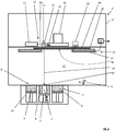
- FIG. 1 in the drawing.
- a device 1 for the production of three-dimensional objects 2 is shown only schematically in relation to FIG .
- the building material 6 is kept ready in a metering chamber 7 which, like the building space 4, is let into a process chamber floor 8.
- a device 9 for applying the building material 6 is designed, for example, as a squeegee device which can be moved over the metering chamber 7 and the building chamber 4 and which picks up building material 6 in the metering chamber 7, applies a thin layer in the area of the building chamber 4 and transfers superfluous building material 6 into an overflow container 10 throws off.
- An irradiation device 12 is provided above or in the upper area of the process chamber 11, which is used to selectively irradiate the applied building material 6 to solidify it; in the exemplary embodiment, the beam 14 of a laser 13 is guided through a scanner 15, the mirror 16 of which is controlled by building data so that the focus 17 of the laser beam 14 impinging on the building material 6 can melt or partially melt the building material 6 and thereby solidify it.
- a camera device 20 for optical detection and / or recording of a melting or solidification process of the building material 6 forming in the focus 17 of the beam of the irradiation device 12 and / or for optical detection and / or monitoring and / or recording a coating process of the building material 6 is provided, the optics 21 of the camera device 20 being separated from the ongoing building process by a protective camera glass 30 or the optics of the scanner 15 by a radiation reflection glass.
- the radiation reflection glass can also be used as camera protective glass 30 and the camera protective glass 30, if designed accordingly, also as radiation reflection glass, which is why in the exemplary embodiment only one protective glass is arranged or shown in front of the two optical elements camera and scanner.
- the protective glass is designed and mounted so that it can be driven such that parts of the protective glass are continuously guided through a glass cleaning device 31 while the construction process and / or camera observation process is running, with at least one other section of the protective glass remaining in front of the camera optics and / or the irradiation optics during the cleaning process.
- the protective glass 30 is arranged horizontally and driven about a vertical axis 32 by an electric motor 33.
- the glass cleaning device 35 is arranged laterally next to the optical axis of the camera device 20 and / or the irradiation optics, namely scanner 15.
- the glass cleaning device 31 comprises at least one cleaning element 35 in the form of a brush, which acts on the underside 36 of the protective glass 30 and removes any smoke particles and the like adhering to it into a collecting container 37.
- the glass cleaning device 31 is encapsulated as a whole with respect to the process chamber 11, i. H. it is ensured that particles present in the glass cleaning device 31 or in the collecting container 37 cannot get onto the building surface.
- the invention further comprises a sensor 40 which is arranged in or on the glass cleaning device 31 and which can detect the contamination of the protective glass 30.
- the sensor 40 is preferably an optical sensor which, through transmission of the protective glass 30, determines whether and, if so, how particles adhere to the underside of the protective glass 30.
- the sensor can also be formed by the camera,
- the speed of the motor drive 33 of the pane or of the cleaning element 35 can be controlled as a function of the result of the degree of soiling of the glass detected by the sensor 40.
- the collecting container 37 can be sucked off by means of a suction device 41 during the construction process and thus emptied.
- Two glass cleaning devices 31a and 31b are arranged to the left and right of the camera and / or the optical elements of the irradiation device 12, the protective glass 30 can be moved to the left and right so that all areas of the protective glass 30 can be cleaned at intervals and always on Section of the protective glass 30 either in front of the camera optics or the irradiation optics remains.
Landscapes
- Engineering & Computer Science (AREA)
- Chemical & Material Sciences (AREA)
- Materials Engineering (AREA)
- Manufacturing & Machinery (AREA)
- Physics & Mathematics (AREA)
- Optics & Photonics (AREA)
- Mechanical Engineering (AREA)
- Analytical Chemistry (AREA)
- Automation & Control Theory (AREA)
- Plasma & Fusion (AREA)
- Laser Beam Processing (AREA)
- Powder Metallurgy (AREA)
Description
- Die Erfindung betrifft eine Vorrichtung zur Herstellung dreidimensionaler Objekte, insbesondere eine SLM- oder eine SLS-Vorrichtung mit den weiteren Merkmalen des Oberbegriffes des Anspruches 1. Zudem betrifft die Erfindung auch ein zugehöriges Verfahren mit den Merkmalen des Anspruches 13.
- Wenn von einer Vorrichtung zur Herstellung dreidimensionaler Objekte im Zusammenhang mit dem Oberbegriff des Anspruches 1 gesprochen wird, so sind damit sämtliche auch als "3D-Drucker" bekannte Vorrichtungen angesprochen, die ausgebildet und geeignet sind, durch einen schichtweisen Auftrag eines pulverförmigen, flüssigen oder pastosem Baumaterials auf eine Unterlage oder eine bereits gebildete Schicht dreidimensionale Gegenstände zu bauen, wobei die Schicht selektiv durch Strahlung, insbesondere Laserstrahlung in einen verfestigten Zustand überführt wird, sodass das gewünschte Bauteil aus abgespeicherten Baudaten schichtweise aufgebaut werden kann. Angesprochen sind insbesondere Kunstoff-Iasersinter- - oder - laserschmelzanlagen, Metallpulver-Iasersinter- oder -laserschmelzanlagen oder Stereolithographieanlagen, bei denen ein flüssiges harzartiges Material schichtweise aufgetragen und dann selektiv entsprechend den zur Verfügung stehenden Baudaten verfestigt wird.
- Bei den angesprochenen Anlagen ist in einem Gehäuse ein Bauraum angeordnet, in welchem eine Auflage zum Tragen des sich bildenden Objektes vorgesehen ist. Außerdem ist eine Vorrichtung zum schichtweisen Auftragen von Baumaterial auf die Tragevorrichtung oder eine bereits gebildete Schicht vorhanden. Eine Bestrahlungseinrichtung ist über der Schicht zum selektiven Bestrahlen des aufgetragenen Baumaterials zu dessen Verfestigung vorhanden, wobei wenigstens ein Strahl der Bestrahlungseinrichtung abhängig von den Baudaten auf das Baumaterial geführt wird. Meist erfolgt die Führung des wenigstens einen Strahls der Bestrahlungseinrichtung abhängig von den Baudaten über eine Scannereinrichtung, es fallen unter den Gegenstand der Erfindung aber auch Vorrichtungen, bei denen durch eine Vielzahl von Strahlungsquellen, die ortsfest oder beweglich angeordnet sein können, eine selektive Bestrahlung des Baumaterials erfolgt. Auch ist es möglich, nur eine Strahlungsquelle, z. B. einen Laser gezielt und selektiv abhängig von gespeicherten Baudaten über der Oberfläche des Baumaterials zu führen.
- Zur Verbesserung laufender Bauprozesse und/oder Beschichtungsprozesse des Baumaterials ist es wünschenswert, eine Kameravorrichtung vorzusehen, die zur optischen Erfassung und/oder auch Aufzeichnung einer sich im Fokus des Strahls der Bestrahlungseinrichtung bildenden Aufschmelz- oder Verfestigungsprozesses des Baumaterials geeignet ist. Eine solche Kamera kann aber auch zur optischen Erfassung und/oder Überwachung oder Aufzeichnung eines Beschichtungsprozesses des Baumaterials auf der Tragevorrichtung dienen, mit anderen Worten, kann entweder der Bauprozess selbst bei der selektiven Verfestigung des Baumaterials beobachtet, überwacht und aufgezeichnet werden, um z. B. eine Qualitätskontrolle des Baumaterials durchzuführen, und/oder bereits vor Belichtung der Beschichtungsprozess überwacht werden, um eine qualitative Überprüfung eines Baumaterialcoatings vorzunehmen, da eine fehlerfrei aufgebrachte Baumaterialschicht extrem wichtig für die Qualität des entstehenden Bauteils ist.
- Bekanntermaßen sind optische Frontlinsen von Kameraeinrichtungen, Scannern oder sonstigen Belichtungselementen empfindlich gegen Verschmutzung z. B. durch Schmauch oder Baumaterialspritzer oder dgl., die in einem Bauraum einer derartigen SLM- oder SLS-Vorrichtung oder sonstigen 3D-Druckvorrichtungen auftreten können. Aus diesem Grunde wurde bereits dazu übergegangen, Schutzgläser zwischen der Zone des Bauprozesses und der Kameraoptik anzuordnen (z. B.
DE 10 2010 052 206 A1 ). - Es wurde auch bereits diskutiert, ein Strahlungsreflexionsglas zwischen der Kameraoptik und der Zone des Bauprozesses vorzusehen, da bei bestimmten Materialien wie z. B. Edelmetallen eine Reflexion des Laserstrahls "in sich" zu einer Störung der Entladung des Lasers führen kann, was den Bauprozess negativ beeinflusst (
DE 10 2014 005 915 A1 ). -
DE 10 2013 219 961 A1 offenbart eine additive Fertigungsanlage für die Herstellung von Fahrzeugbauteilen, aufweisend einen Sinterraum und eine Laserlichtquelle für einen Energieeintrag in ein Sintermaterial. Zwischen dem Sinterraum und der Laserlichtquelle ist ein Wechselrahmen mit wenigstens einem Einkoppelfenster für die Transmission von Laserlicht der Laserlichtquelle angeordnet. - Derartige "Schutzgläser" müssen möglichst frei von Verschmutzung gehalten werden. Dazu wurde bereits diskutiert, eine Gasströmung in der Baukammer so zu führen, dass Schmauch und Dämpfe von einer Schutzglasvorrichtung oder Reflexionsglasvorrichtung möglichst ferngehalten werden.
- Der Erfindung liegt die Aufgabe zugrunde, eine Vorrichtung mit den Merkmalen des Oberbegriffes des Anspruches 1 bzw. ein Verfahren mit den Merkmalen des Anspruches 13 derart weiterzubilden, dass eine Überwachung des Beschichtungs- oder Bauprozesses auch bei sehr langen, stark schmauchenden Bauprozessen ohne Unterbrechung möglich ist. Insbesondere soll eine manuelle Reinigung der Vorrichtung, insbesondere des Schutzglases entfallen können. Insbesondere soll aber auch vermieden werden, dass Reinigungselemente für das Schutzglas zeit- oder abschnittsweise den Strahlengang durchsetzen, was ebenfalls zu einer Störung des Bauprozesses führen würde.
- Diese Aufgabe wird dadurch gelöst, dass das Kameraschutzglas und/oder das Strahlungsreflexionsglas derart ausgebildet und antreibbar gelagert ist, dass Teile des Kameraschutzglases und/oder Strahlungsreflexionsglases bei laufendem Bauprozess und Kamerabetriebes kontinuierlich durch eine Glasreinigungsvorrichtung geführt sind, wobei während der Reinigung wenigstens ein Abschnitt des Kameraschutzglases oder Reflexionsglases vor der Kameraoptik angeordnet ist.
- Kern der Erfindung ist damit wenigstens eine Glasreinigungsvorrichtung, die seitlich neben dem Strahlengang der Kamera oder der Verfestigungsstrahlenquelle so angeordnet ist, dass jeweils ein Teil des Schutz- oder Reflexionsglases kontinuierlich oder oszillierend oder drehend durch die Reinigungsvorrichtung geführt werden kann. Wesentlich ist dabei, dass der Reinigungsprozess den Bauprozess und/oder den Beobachtungsprozess nicht negativ beeinträchtigt oder gar unterbricht. Das Schutz- oder Reflexionsglas kann vor der Linse der Kamera oder vor der Bestrahlungseinrichtung horizontal angeordnet sein und um eine vertikale Achse drehangetrieben werden. Es liegt aber auch im Rahmen der Erfindung, eine schräge Anordnung des Schutzglases vorzusehen und die Drehachse entsprechend schräg zu stellen. Grundsätzlich ist es aber auch möglich, ein Schutz- oder Reflexionsglas oszillierend vor der Kameraeinrichtung hin und her zu bewegen und dabei einseitig oder auf beiden Seiten Reinigungselemente vorzusehen, die bei dem hin- und her bewegten Schutz- oder Reflexionsglas dessen Unterseite reinigen. Ein Reinigungselement sollte relativ zu der zu reinigenden Glasoberfläche, insbesondere Glasunterseite bewegbar sein. Die Relativbewegung kann z. B. dadurch herbeigeführt werden, dass das Glas bewegt wird, aber auch das Reinigungselement zum Beispiel in Form einer Bürste oder Lippe hin- und her bewegt wird oder rotatorisch oder vibrierend angetrieben ist. Auch ein Ultraschallreinigungselement oder -bad liegt im Rahmen der Erfindung. Die Glasreinigungsvorrichtung sollte gegenüber dem Bauraum gekapselt sein, es muss sichergestellt werden, dass von der Glasunterseite abgetragener Schmutz nicht auf die Bauoberfläche fällt. Dazu ist ein Auffangbehälter vorgesehen, der Schmauchreste und dgl. aufnehmen kann.
- Das Schutzglas kann auch eine schmutzabweisende Beschichtung aufweisen, die den Reinigungsvorgang unterstützt.
- Um Schutz- oder Reflexionsglasbewegungen auf ein Minimum zu beschränken, ist es im Rahmen der Erfindung vorteilhaft, wenn der Verschmutzungsgrad laufend oder in zeitlichen Abständen detektiert wird und eine Reinigung nur dann initiiert wird, wenn wirklich eine den Bau- oder Überwachungsprozess beeinträchtigende Verschmutzung der Glasunterseite vorliegt. Dies kann durch einen optischen Sensor geschehen. Es ist aber auch möglich, dass der optische Sensor durch die Kamera selbst gebildet wird, die z. B. ein Referenzmuster unterhalb des Schutz- oder Reflexionsglases auf Klarheit und Kontrast auswertet. Die Geschwindigkeit des motorischen Antriebs der zu reinigenden Scheibe oder des Reinigungselementes kann abhängig vom Verschmutzungsgrad des Glases gesteuert werden. Der Verschmutzungsgrad kann auf unterschiedliche Weise ermittelt werden, z. B. auch durch einen auf die anhaftenden Partikel reagierenden Oberflächenwellensensor, der für Partikel und/oder Flüssigkeitshaftungen eingesetzt wird. Auch ist es zweckdienlich, wenn insbesondere bei langen Bauprozessen der Reinigungsbehälter während des Bauprozesses entleert werden kann, um den Reinigungsbehälter möglichst kompakt zu halten.
- Die Erfindung ist anhand von Ausführungsbeispielen näher erläutert. Diese zeigen:
- Fig. 1
- eine Vorrichtung gemäß der Erfindung mit einer rotierenden Schutzscheibe;
- Fig. 2
- eine ähnlich aufgebaute Vorrichtung, bei der die Schutzscheibe hin und her schiebbar angeordnet ist und bei der zwei Reinigungsvorrichtungen vorgesehen sind.
- Zunächst wird auf Zeichnungsfigur 1 Bezug genommen.
- Zu Zeichnungsfigur 1 ist lediglich schematisch eine Vorrichtung 1 zur Herstellung dreidimensionaler Objekte 2 dargestellt, bei der in einem Gehäuse 3 der Vorrichtung 1 ein Bauraum 4 angeordnet ist, in welchem eine Auflage 5 zum Tragen des sich bildenden Objektes 2 bzw. des Baumaterials 6 vorgesehen ist. Das Baumaterial 6 wird in einer Dosierkammer 7 bereitgehalten, die wie der Bauraum 4 in einem Prozesskammerboden 8 eingelassen ist. Eine Vorrichtung 9 zum Auftragen des Baumaterials 6 ist zum Beispiel als über der Dosierkammer 7 und der Baukammer 4 verfahrbare Rakelvorrichtung ausgebildet, die in der Dosierkammer 7 Baumaterial 6 aufnimmt, im Bereich der Baukammer 4 eine dünne Schicht aufträgt und überflüssiges Baumaterial 6 in einen Überlaufbehälter 10 abwirft.
- Über oder im oberen Bereich der Prozesskammer 11 ist eine Bestrahlungsreinrichtung 12 vorgesehen, die zum selektiven Bestrahlen des aufgetragenen Baumaterials 6 zu dessen Verfestigung dient, wobei beim Ausführungsbeispiel der Strahl 14 eines Lasers 13 durch einen Scanner 15 geführt wird, dessen Spiegel 16 durch Baudaten gesteuert sind, sodass der auf das Baumaterial 6 auftreffende Fokus 17 des Laserstrahls 14 das Baumaterial 6 auf- oder anschmelzen und dadurch verfestigen kann.
- Weiterhin ist im oberen Bereich der Vorrichtung 1, d. h. über der Prozesskammer oder in einer Prozesskammerdecke eine Kameravorrichtung 20 zur optischen Erfassung und/oder auch Aufzeichnung eines sich im Fokus 17 des Strahls der Bestrahlungseinrichtung 12 bildenden Aufschmelz- oder Verfestigungsprozesses des Baumaterials 6 und/oder zur optischen Erfassung und/oder Überwachung und/oder Aufzeichnung eines Beschichtungsprozesses des Baumaterials 6 vorgesehen, wobei die Optik 21 der Kameravorrichtung 20 durch ein Kameraschutzglas 30 oder die Optik des Scanners 15 durch ein Strahlungsrefelxionsglas von dem laufenden Bauprozess getrennt ist.
- Es sei angemerkt, dass das Strahlungsrefelxionsglas auch als Kameraschutzglas 30 eingesetzt werden kann und das Kameraschutzglas 30 bei entsprechender Ausbildung auch als Strahlungsrefelxionsglas, weswegen im Ausführungsbeispiel vor den beiden optischen Elementen Kamera und Scanner nur ein Schutzglas angeordnet oder dargestellt ist.
- Es liegt aber auch im Rahmen der Erfindung, für die Kamera einerseits und den Scanner andererseits jeweils getrennte Schutzgläser vorzusehen, die aber auf die entsprechende nachfolgend beschriebene Weise gereinigt werden können.
- Das Schutzglas ist derart ausgebildet und antreibbar gelagert, dass Teile des Schutzglases bei laufendem Bauprozess und/oder Kamerabeobachtungsprozess kontinuierlich durch eine Glasreinigungsvorrichtung 31 geführt werden, wobei während der Reinigung wenigstens ein anderer Abschnitt des Schutzglases vor der Kameraoptik und/oder der Bestrahlungsoptik verbleibt.
- Bei dem in der
Figur 1 dargestellten Ausführungsbeispiel ist das Schutzglas 30 horizontal angeordnet und um eine vertikale Achse 32 durch einen Elektromotor 33 angetrieben. - Die Glasreinigungsvorrichtung 35 ist seitlich neben der optischen Achse der Kameraeinrichtung 20 und/oder der Bestrahlungsoptik, nämlich Scanner 15 angeordnet.
- Die Glasreinigungsvorrichtung 31 umfasst wenigstens ein als Bürste ausgebildetes Reinigungselement 35, das die Unterseite 36 des Schutzglases 30 beaufschlagt und daran anhaftende Schmauchpartikel und dgl. in einen Auffangbehälter 37 ablöst.
- Die Glasreinigungsvorrichtung 31 ist insgesamt gegenüber der Prozesskammer 11 gekapselt, d. h. es ist sichergestellt, dass in der Glasreinigungsvorrichtung 31 bzw. im Auffangbehälter 37 vorhandene Partikel nicht auf die Bauoberfläche gelangen können.
- Die Erfindung umfasst weiterhin einen in- oder an der Glasreinigungsvorrichtung 31 angeordneten Sensor 40, der die Verschmutzung des Schutzglases 30 detektieren kann. Der Sensor 40 ist vorzugsweise ein optischer Sensor, der durch eine Transmission des Schutzglases 30 feststellt, ob und ggf. wie Partikel an der Unterseite des Schutzglases 30 anhaften. Der Sensor kann aber auch durch die Kamera gebildet werden,
- Die Geschwindigkeit des motorischen Antriebs 33 der Scheibe oder des Reinigungselementes 35 ist abhängig vom Ergebnis des durch den Sensor 40 detektierten Verschmutzungsgrad des Glases steuerbar.
- Der Auffangbehälter 37 kann über eine Absaugvorrichtung 41 während des Bauprozesses abgesaugt und damit geleert werden.
- In
Figur 2 ist eine in weitgehenden Abschnitten zuFigur 1 identische Vorrichtung dargestellt, allerdings ist der Elektromotor 33 nicht dazu ausgebildet, eine Achse 32 sind das Schutzglas 30 drehanzutreiben, sondern das Schutzglas 20 ist über nicht dargestellte Führungselemente nach links und rechts verschiebbar gelagert, der Elektromotor 33 weist Rollensätze 50 auf, durch die das Schutzglas 20 nach links und rechts durch Reibkontakt verschoben wird. - Links und rechts von der Kamera und/oder den optischen Elementen der Bestrahlungseinrichtung 12 sind zwei Glasreinigungsvorrichtungen 31a und 31b angeordnet, das Schutzglas 30 kann so nach links und rechts verfahren werden, dass alle Bereiche des Schutzglases 30 in zeitlichen Abständen gereinigt werden können und immer ein Abschnitt des Schutzglases 30 entweder vor der Kameraoptik oder der Bestrahlungsoptik verbleibt.
Claims (13)
- Vorrichtung (1) zur Herstellung dreidimensionaler Objekte (2), insbesondere eine SLM, SLS, selektive Laserschmelz-oder selektive Lasersintervorrichtung im Wesentlichen umfassend:- einen in einem Gehäuse (3) der Vorrichtung (1) angeordneten Bauraum (4), in welchem eine Auflage (5) zum Tragen des sich bildenden Objektes (2) vorgesehen ist,- eine Vorrichtung (9) zum Auftragen von Schichten des Baumaterials (6) auf die Auflage (5) oder eine zuvor gebildete Schicht,- eine Bestrahlungseinrichtung (12) zum selektiven Bestrahlen des aufgetragenen Baumaterials (6) zu dessen Verfestigung, wobei wenigstens ein Strahl (14) der Bestrahlungseinrichtung (12) abhängig von gespeicherten Baudaten auf das Baumaterial (6) geführt wird, dadurch gekennzeichnet, dass- eine Kameravorrichtung (20) zur optischen Erfassung und/oder Aufzeichnung eines sich im Fokus (17) des Strahls der Bestrahlungseinrichtung (12) bildenden Aufschmelz- oder Verfestigungsprozesses des Baumaterials (6) und/oder zur optischen Erfassung und/oder Überwachung und/oder Aufzeichnung eines Beschichtungsprozesses des Baumaterials (6) auf der Tragevorrichtung angeordnet ist, wobei die Optik (21) der Kameravorrichtung (20) oder die der Bestrahlungseinreichtung (12) durch ein Schutzglas (30) von dem laufenden Bauprozess getrennt ist, wobei- das Schutzglas (30) derart ausgebildet und antreibbar gelagert ist, dass Teile des Schutzglases (30) bei laufendem Bauprozess und/oder Kamerabeobachtungsprozess durch eine Glasreinigungsvorrichtung (31) geführt sind, wobei während der Reinigung wenigstens ein Abschnitt des Schutzglases (30) vor der Kameraoptik und/oder der Bestrahlungsoptik angeordnet ist.
- Vorrichtung nach Anspruch 1, dadurch gekennzeichnet, dass das Schutzglas (30) um eine vertikale Achse (32) drehangetrieben ist.
- Vorrichtung nach Anspruch 2, dadurch gekennzeichnet, dass wenigstens eine Glasreinigungsvorrichtung (31) seitlich neben der optischen Achse der Kameraeinrichtung und/oder der Bestrahlungseinrichtung (12) angeordnet ist.
- Vorrichtung nach einem der vorhergehenden Ansprüche, dadurch gekennzeichnet, dass die Glasreinigungsvorrichtung (31) wenigstens ein Reinigungselement (35) umfasst, das die Unterseite (36) des Schutzglases (30) beaufschlagt.
- Vorrichtung nach Anspruch 4, dadurch gekennzeichnet, dass das Reinigungselement (35) eine Bürste, eine Lippe oder ein sonstiges Abstreifelement ist oder als in einem Ultraschallbad angeordnete Reinigungseinheit ausgeildetist.
- Vorrichtung nach Anspruch 5, dadurch gekennzeichnet, dass die Bürste oder das Abstreifelement mechanisch gegenüber dem Schutzglas (30) bewegbar ist.
- Vorrichtung nach einem der vorhergehenden Ansprüche, dadurch gekennzeichnet, dass die Glasreinigungsvorrichtung (31) gegenüber der Prozesskammer gekapselt ist.
- Vorrichtung nach einem der vorhergehenden Ansprüche, dadurch gekennzeichnet, dass die Glasreinigungsvorrichtung (31) einen Auffangbehälter (37) für die von dem Schutzglas (30) abgenommenen Schmauchreste umfasst.
- Vorrichtung nach einem der vorhergehenden Ansprüche, dadurch gekennzeichnet, dass in/oder an der Glasreinigungsvorrichtung (31) ein Sensor (40) angeordnet ist, der die Verschmutzung des Schutzglases (30) detektiert.
- Vorrichtung nach Anspruch 9, dadurch gekennzeichnet, dass der Sensor (40) durch die Kamera (20) oder einen Oberflächenwellensensor gebildet wird.
- Vorrichtung nach einem der vorhergehenden Ansprüche, dadurch gekennzeichnet, dass die Geschwindigkeit des motorischen Antriebes (33) der Scheibe und/oder des Reinigungselementes (35) abhängig vom Ergebnis des Verschmutzungsgrades des Schutzglases (30) steuerbar ist.
- Vorrichtung nach einem der vorhergehenden Ansprüche, dadurch gekennzeichnet, dass der Auffangbehälter (37) während des Bauprozesses entleerbar ist.
- Verfahren zur Reinigung eines optischen Schutzglases (30) in einer Vorrichtung (1) zur Herstellung dreidimensionaler Objekte (2), insbesondere SLM- oder SLS-Vorrichtung, mit folgenden Merkmalen:- Vorsehen eines in einem Gehäuse (3) der Vorrichtung (1) angeordneten Bauraumes (4), in welchem eine Auflage (5) zum Tragen des sich bildenden Objektes (2) höhenverstellbar gelagert ist;- Vorsehen einer Vorrichtung (9) zum Auftragen von Schichten des Baumaterials (6) auf die Auflage (5) oder eine zuvor gebildete Schicht;- Vorsehen einer Bestrahlungseinrichtung (12) zum selektiven Bestrahlen des aufgetragenen Baumaterials (6) zu dessen Verfestigung, wobei wenigstens ein Strahl der Bestrahlungseinrichtung (12) von gespeicherten Baudaten auf das Baumaterial (6) geführt ist, dadurch gekennzeichnet, dass- eine Kameravorrichtung (20) zur optischen Erfassung und/oder Aufzeichnung eines sich im Fokus (17) des wenigstens einen Strahls (14) der Bestrahlungseinrichtung (12) bildenden Aufschmelz- oder Verfestigungsprozesses des Baumaterials (6) und/oder zur optischen Erfassung und/oder Überwachung und/oder Aufzeichnung eines Beschichtungsprozesses des Baumaterials auf der Tragevorrichtung vorgesehen ist, wobei das Schutzglas (30) vor der Optik (21) der Kameravorrichtung (20) und/oder vor der Optik (21) der Bestrahlungseinrichtung (12) angeordnet ist und eine bewegliche Lagerung des Schutzglases (30) derart vorgesehen ist, dass ein Abschnitt des Schutzglases (30) bei laufendem Bauprozess und/oder Kamerabeobachtungsprozess und/oder Beschichtungsprozess kontinuierlich durch eine Glasreinigungsvorrichtung (31) geführt wird und während der so durchgeführten Reinigung des wenigstens einen Abschnittes des Schutzglases (30) ein anderer Abschnitt des Schutzglases (30) vor der Optik der Kameraeinrichtung oder der Bestrahlungseinrichtung (12) verbleibt.
Applications Claiming Priority (1)
| Application Number | Priority Date | Filing Date | Title |
|---|---|---|---|
| DE102016117633.8A DE102016117633A1 (de) | 2016-09-19 | 2016-09-19 | Vorrichtung zur Herstellung dreidimensionaler Objekte |
Publications (2)
| Publication Number | Publication Date |
|---|---|
| EP3296080A1 EP3296080A1 (de) | 2018-03-21 |
| EP3296080B1 true EP3296080B1 (de) | 2021-08-04 |
Family
ID=59009602
Family Applications (1)
| Application Number | Title | Priority Date | Filing Date |
|---|---|---|---|
| EP17174400.6A Active EP3296080B1 (de) | 2016-09-19 | 2017-06-02 | Vorrichtung zur herstellung dreidimensionaler objekte |
Country Status (5)
| Country | Link |
|---|---|
| US (1) | US11007574B2 (de) |
| EP (1) | EP3296080B1 (de) |
| JP (1) | JP6486425B2 (de) |
| CN (1) | CN107839233B (de) |
| DE (1) | DE102016117633A1 (de) |
Families Citing this family (9)
| Publication number | Priority date | Publication date | Assignee | Title |
|---|---|---|---|---|
| EP3727711B1 (de) * | 2018-04-23 | 2021-07-28 | Carbon, Inc. | Verfahren und harzextraktor für die generative fertigung |
| CN113412186B (zh) | 2018-12-11 | 2023-04-04 | Io技术集团公司 | 用于使用惰性气体防止在3d打印系统中光引发聚合反应的氧阻聚的系统和方法 |
| CN109967737A (zh) * | 2018-12-26 | 2019-07-05 | 西安铂力特增材技术股份有限公司 | 一种用于3d打印设备光学元件保护镜片的自动清洁装置 |
| JP7259362B2 (ja) * | 2019-01-30 | 2023-04-18 | 三菱電機株式会社 | レーザ加工ヘッド、劣化検知装置及びレーザ加工機 |
| CN110238398B (zh) * | 2019-07-01 | 2022-01-04 | 广州大学 | 一种slm型金属3d打印机的透镜保护装置 |
| FR3102397B1 (fr) * | 2019-10-24 | 2022-10-14 | Addup | Machine à faisceau laser comprenant un dispositif d’application d’une couche de gel optique sur une vitre traversée par le faisceau laser. |
| US11752558B2 (en) | 2021-04-16 | 2023-09-12 | General Electric Company | Detecting optical anomalies on optical elements used in an additive manufacturing machine |
| US12275066B2 (en) * | 2021-10-05 | 2025-04-15 | Nikon Corporation | Systems and methods for improved melting in three-dimensional printing processes |
| FR3143417B1 (fr) | 2022-12-15 | 2025-02-14 | Addup | Machine de fabrication additive comprenant un système de remplacement d’une vitre équipant une paroi de l’enceinte de fabrication. |
Family Cites Families (15)
| Publication number | Priority date | Publication date | Assignee | Title |
|---|---|---|---|---|
| JP2895683B2 (ja) * | 1992-07-30 | 1999-05-24 | 住友電気工業株式会社 | 酸化物超電導膜製造装置 |
| US6796746B2 (en) * | 2002-10-22 | 2004-09-28 | Bachtel Bwxt Idaho, Llc | Subterranean drilling and in situ treatment of wastes using a contamination control system and methods relating thereto |
| DE102006047794A1 (de) | 2006-10-06 | 2008-04-10 | Mobil-Mark Gmbh | Laseranordnung zur Bearbeitung der Oberfläche eines Werkstücks |
| US8105066B2 (en) * | 2007-01-17 | 2012-01-31 | 3D Systems, Inc. | Cartridge for solid imaging apparatus and method |
| US8070474B2 (en) | 2007-05-30 | 2011-12-06 | Panasonic Electric Works Co., Ltd. | Lamination shaping apparatus |
| DE102008037345A1 (de) | 2008-08-12 | 2010-02-25 | Andreas Trautmann | Gasdüse mit Schutzglaseinheit und Verfahren zum Schweißen/Schneiden eines Werkstücks |
| DE102010052206B4 (de) | 2010-11-10 | 2015-06-18 | Cl Schutzrechtsverwaltungs Gmbh | Vorrichtung zum Herstellen von dreidimensionalen Objekten |
| EP2537665A1 (de) * | 2011-06-22 | 2012-12-26 | 3D Systems, Inc. | Verbesserungen für Vorrichtung zur schnellen Erstellung von Prototypen und Verfahren |
| CN105209192B (zh) * | 2013-04-26 | 2018-06-01 | 联合工艺公司 | 增材制造中的局部污染检测 |
| DE102013219961A1 (de) * | 2013-10-01 | 2015-04-02 | Bayerische Motoren Werke Aktiengesellschaft | Additive Fertigungsanlage für die Herstellung von Fahrzeugbauteilen |
| DE102014005915A1 (de) | 2014-04-25 | 2015-10-29 | Cl Schutzrechtsverwaltungs Gmbh | Vorrichtung zur generativen Herstellung dreidimensionaler Objekte |
| DE102014212246B3 (de) | 2014-06-26 | 2015-08-06 | MTU Aero Engines AG | Verfahren und Vorrichtung zur Qualitätssicherung |
| KR101962053B1 (ko) * | 2014-12-26 | 2019-03-25 | 파나소닉 아이피 매니지먼트 가부시키가이샤 | 삼차원 형상 조형물의 제조 방법 |
| CN105128343A (zh) * | 2015-10-14 | 2015-12-09 | 湖南华曙高科技有限责任公司 | 多色三维物体的制造方法及装置 |
| WO2018013829A1 (en) * | 2016-07-13 | 2018-01-18 | Xiaoyu Zheng | 3d printing systems and methods thereof |
-
2016
- 2016-09-19 DE DE102016117633.8A patent/DE102016117633A1/de not_active Ceased
-
2017
- 2017-06-02 EP EP17174400.6A patent/EP3296080B1/de active Active
- 2017-07-31 CN CN201710638214.5A patent/CN107839233B/zh active Active
- 2017-08-08 JP JP2017153250A patent/JP6486425B2/ja active Active
- 2017-09-19 US US15/709,265 patent/US11007574B2/en active Active
Non-Patent Citations (1)
| Title |
|---|
| None * |
Also Published As
| Publication number | Publication date |
|---|---|
| EP3296080A1 (de) | 2018-03-21 |
| JP6486425B2 (ja) | 2019-03-20 |
| JP2018047687A (ja) | 2018-03-29 |
| DE102016117633A1 (de) | 2018-03-22 |
| CN107839233B (zh) | 2020-05-01 |
| US11007574B2 (en) | 2021-05-18 |
| US20180079004A1 (en) | 2018-03-22 |
| CN107839233A (zh) | 2018-03-27 |
Similar Documents
| Publication | Publication Date | Title |
|---|---|---|
| EP3296080A1 (de) | Vorrichtung zur herstellung dreidimensionaler objekte | |
| DE102015121748B4 (de) | Strömungseinrichtung für eine Vorrichtung zur generativen Herstellung eines dreidimensionalen Objekts, Vorrichtung mit einer solchen Strömungseinrichtung und Verfahren zur Herstellung eines dreidimensionalen Objekts unter Verwendung einer Vorrichtung und einer entsprechenden Strömungseinrichtung | |
| EP0688262B2 (de) | Verfahren und vorrichtung zum herstellen eines dreidimensionalen objekts | |
| DE202006016477U1 (de) | Vorrichtung zum Herstellen eines dreidimensionalen Objektes | |
| DE102015116923B4 (de) | 3D-Drucker | |
| US11911957B2 (en) | Methods for damage detection during additive manufacturing of at least one three-dimensional object using detected layer information and smoothness | |
| DE102015207254A1 (de) | Vorrichtung und Verfahren zur generativen Herstellung eines dreidimensionalen Objektes | |
| DE102011009345B3 (de) | Verfahren und Vorrichtung zur Erfassung einer Partikeldichteverteilung im Strahl einer Düse | |
| EP3245043A1 (de) | Vorrichtung zur generativen herstellung dreidimensionaler bauteile | |
| EP1250997A1 (de) | Vorrichtung zum Herstellen eines dreidimensionalen Objekts | |
| DE102011017684A1 (de) | Abdeckung für einen optischen Sensor für ein Fahrzeug und optische Sensorvorrichtung für ein Fahrzeug | |
| DE102018217751A1 (de) | Laserbearbeitungsvorrichtung | |
| DE102007014968A1 (de) | Vorrichtung zur Herstellung von Gegenständen | |
| DE102010029078A1 (de) | Verfahren zur Herstellung eines Gegenstandes durch schichtweises Aufbauen aus pulverförmigem Werkstoff | |
| DE10236907A1 (de) | Vorrichtung zur Herstellung eines Formkörpers durch schichtweises Aufbauen aus pulverförmigem, insbesondere metallischem oder keramischem Werkstoff | |
| WO2016113255A1 (de) | Verfahren zur herstellung von dreidimensionalen bauteilen | |
| DE102006041320A1 (de) | Beschichtereinrichtung für eine Bauvorrichtung zur Erstellung von Formteilen aus pulverartigem Baumaterial unter Einbringung von Strahlungsenergie | |
| EP1297561A1 (de) | Verfahren und vorrichtung zum reinigen und anschliessendem bonden von substraten | |
| DE29911122U1 (de) | Vorrichtung zum Herstellen eines dreidimensionalen Objektes | |
| DE102004061836C5 (de) | Schichtweiser Aufbau von Festkörpern durch zweistufigen Materialtransport über eine rotierende Scheibe | |
| DE102017213072A1 (de) | Additives Fertigungsverfahren | |
| EP2796273B1 (de) | Schutzvorrichtung für generative Fertigungsverfahren, damit versehene Fertigungsvorrichtung sowie damit durchführbares generatives Fertigungsverfahren | |
| EP4719677A2 (de) | Verfahren zur steuerung des betriebs einer siebvorrichtung, siebvorrichtung, pulveraufbereitungssystem und anlage zur herstellung von dreidimensionalen werkstücken | |
| DE102011106380B4 (de) | Vorrichtung zur Herstellung von dreidimensionalen Objekten | |
| DE20318721U1 (de) | Vorrichtung zur Herstellung eines Formkörpers durch schichtweises Aufbauen aus pulverförmigem, insbesondere metallischem oder keramischem Werkstoff |
Legal Events
| Date | Code | Title | Description |
|---|---|---|---|
| PUAI | Public reference made under article 153(3) epc to a published international application that has entered the european phase |
Free format text: ORIGINAL CODE: 0009012 |
|
| STAA | Information on the status of an ep patent application or granted ep patent |
Free format text: STATUS: THE APPLICATION HAS BEEN PUBLISHED |
|
| AK | Designated contracting states |
Kind code of ref document: A1 Designated state(s): AL AT BE BG CH CY CZ DE DK EE ES FI FR GB GR HR HU IE IS IT LI LT LU LV MC MK MT NL NO PL PT RO RS SE SI SK SM TR |
|
| AX | Request for extension of the european patent |
Extension state: BA ME |
|
| STAA | Information on the status of an ep patent application or granted ep patent |
Free format text: STATUS: REQUEST FOR EXAMINATION WAS MADE |
|
| 17P | Request for examination filed |
Effective date: 20180410 |
|
| RBV | Designated contracting states (corrected) |
Designated state(s): AL AT BE BG CH CY CZ DE DK EE ES FI FR GB GR HR HU IE IS IT LI LT LU LV MC MK MT NL NO PL PT RO RS SE SI SK SM TR |
|
| RIC1 | Information provided on ipc code assigned before grant |
Ipc: B29C 64/35 20170101AFI20201110BHEP Ipc: B33Y 40/00 20200101ALN20201110BHEP Ipc: B33Y 30/00 20150101ALN20201110BHEP Ipc: B29C 64/153 20170101ALI20201110BHEP Ipc: B29C 64/129 20170101ALI20201110BHEP |
|
| RIC1 | Information provided on ipc code assigned before grant |
Ipc: B29C 64/153 20170101ALI20201126BHEP Ipc: B33Y 40/00 20200101ALN20201126BHEP Ipc: B33Y 30/00 20150101ALN20201126BHEP Ipc: B29C 64/129 20170101ALI20201126BHEP Ipc: B29C 64/35 20170101AFI20201126BHEP |
|
| GRAP | Despatch of communication of intention to grant a patent |
Free format text: ORIGINAL CODE: EPIDOSNIGR1 |
|
| STAA | Information on the status of an ep patent application or granted ep patent |
Free format text: STATUS: GRANT OF PATENT IS INTENDED |
|
| RIC1 | Information provided on ipc code assigned before grant |
Ipc: B33Y 40/00 20200101ALN20201211BHEP Ipc: B29C 64/35 20170101AFI20201211BHEP Ipc: B33Y 30/00 20150101ALN20201211BHEP Ipc: B29C 64/129 20170101ALI20201211BHEP Ipc: B29C 64/153 20170101ALI20201211BHEP |
|
| INTG | Intention to grant announced |
Effective date: 20210120 |
|
| GRAS | Grant fee paid |
Free format text: ORIGINAL CODE: EPIDOSNIGR3 |
|
| GRAA | (expected) grant |
Free format text: ORIGINAL CODE: 0009210 |
|
| STAA | Information on the status of an ep patent application or granted ep patent |
Free format text: STATUS: THE PATENT HAS BEEN GRANTED |
|
| AK | Designated contracting states |
Kind code of ref document: B1 Designated state(s): AL AT BE BG CH CY CZ DE DK EE ES FI FR GB GR HR HU IE IS IT LI LT LU LV MC MK MT NL NO PL PT RO RS SE SI SK SM TR |
|
| REG | Reference to a national code |
Ref country code: GB Ref legal event code: FG4D Free format text: NOT ENGLISH |
|
| REG | Reference to a national code |
Ref country code: AT Ref legal event code: REF Ref document number: 1416544 Country of ref document: AT Kind code of ref document: T Effective date: 20210815 |
|
| REG | Reference to a national code |
Ref country code: CH Ref legal event code: EP |
|
| REG | Reference to a national code |
Ref country code: DE Ref legal event code: R096 Ref document number: 502017011074 Country of ref document: DE |
|
| REG | Reference to a national code |
Ref country code: IE Ref legal event code: FG4D Free format text: LANGUAGE OF EP DOCUMENT: GERMAN |
|
| REG | Reference to a national code |
Ref country code: LT Ref legal event code: MG9D |
|
| REG | Reference to a national code |
Ref country code: NL Ref legal event code: MP Effective date: 20210804 |
|
| PG25 | Lapsed in a contracting state [announced via postgrant information from national office to epo] |
Ref country code: SE Free format text: LAPSE BECAUSE OF FAILURE TO SUBMIT A TRANSLATION OF THE DESCRIPTION OR TO PAY THE FEE WITHIN THE PRESCRIBED TIME-LIMIT Effective date: 20210804 Ref country code: RS Free format text: LAPSE BECAUSE OF FAILURE TO SUBMIT A TRANSLATION OF THE DESCRIPTION OR TO PAY THE FEE WITHIN THE PRESCRIBED TIME-LIMIT Effective date: 20210804 Ref country code: FI Free format text: LAPSE BECAUSE OF FAILURE TO SUBMIT A TRANSLATION OF THE DESCRIPTION OR TO PAY THE FEE WITHIN THE PRESCRIBED TIME-LIMIT Effective date: 20210804 Ref country code: ES Free format text: LAPSE BECAUSE OF FAILURE TO SUBMIT A TRANSLATION OF THE DESCRIPTION OR TO PAY THE FEE WITHIN THE PRESCRIBED TIME-LIMIT Effective date: 20210804 Ref country code: HR Free format text: LAPSE BECAUSE OF FAILURE TO SUBMIT A TRANSLATION OF THE DESCRIPTION OR TO PAY THE FEE WITHIN THE PRESCRIBED TIME-LIMIT Effective date: 20210804 Ref country code: PT Free format text: LAPSE BECAUSE OF FAILURE TO SUBMIT A TRANSLATION OF THE DESCRIPTION OR TO PAY THE FEE WITHIN THE PRESCRIBED TIME-LIMIT Effective date: 20211206 Ref country code: NO Free format text: LAPSE BECAUSE OF FAILURE TO SUBMIT A TRANSLATION OF THE DESCRIPTION OR TO PAY THE FEE WITHIN THE PRESCRIBED TIME-LIMIT Effective date: 20211104 Ref country code: BG Free format text: LAPSE BECAUSE OF FAILURE TO SUBMIT A TRANSLATION OF THE DESCRIPTION OR TO PAY THE FEE WITHIN THE PRESCRIBED TIME-LIMIT Effective date: 20211104 Ref country code: LT Free format text: LAPSE BECAUSE OF FAILURE TO SUBMIT A TRANSLATION OF THE DESCRIPTION OR TO PAY THE FEE WITHIN THE PRESCRIBED TIME-LIMIT Effective date: 20210804 |
|
| PG25 | Lapsed in a contracting state [announced via postgrant information from national office to epo] |
Ref country code: PL Free format text: LAPSE BECAUSE OF FAILURE TO SUBMIT A TRANSLATION OF THE DESCRIPTION OR TO PAY THE FEE WITHIN THE PRESCRIBED TIME-LIMIT Effective date: 20210804 Ref country code: LV Free format text: LAPSE BECAUSE OF FAILURE TO SUBMIT A TRANSLATION OF THE DESCRIPTION OR TO PAY THE FEE WITHIN THE PRESCRIBED TIME-LIMIT Effective date: 20210804 Ref country code: GR Free format text: LAPSE BECAUSE OF FAILURE TO SUBMIT A TRANSLATION OF THE DESCRIPTION OR TO PAY THE FEE WITHIN THE PRESCRIBED TIME-LIMIT Effective date: 20211105 |
|
| PG25 | Lapsed in a contracting state [announced via postgrant information from national office to epo] |
Ref country code: NL Free format text: LAPSE BECAUSE OF FAILURE TO SUBMIT A TRANSLATION OF THE DESCRIPTION OR TO PAY THE FEE WITHIN THE PRESCRIBED TIME-LIMIT Effective date: 20210804 |
|
| PG25 | Lapsed in a contracting state [announced via postgrant information from national office to epo] |
Ref country code: DK Free format text: LAPSE BECAUSE OF FAILURE TO SUBMIT A TRANSLATION OF THE DESCRIPTION OR TO PAY THE FEE WITHIN THE PRESCRIBED TIME-LIMIT Effective date: 20210804 |
|
| REG | Reference to a national code |
Ref country code: DE Ref legal event code: R097 Ref document number: 502017011074 Country of ref document: DE |
|
| PG25 | Lapsed in a contracting state [announced via postgrant information from national office to epo] |
Ref country code: SM Free format text: LAPSE BECAUSE OF FAILURE TO SUBMIT A TRANSLATION OF THE DESCRIPTION OR TO PAY THE FEE WITHIN THE PRESCRIBED TIME-LIMIT Effective date: 20210804 Ref country code: SK Free format text: LAPSE BECAUSE OF FAILURE TO SUBMIT A TRANSLATION OF THE DESCRIPTION OR TO PAY THE FEE WITHIN THE PRESCRIBED TIME-LIMIT Effective date: 20210804 Ref country code: RO Free format text: LAPSE BECAUSE OF FAILURE TO SUBMIT A TRANSLATION OF THE DESCRIPTION OR TO PAY THE FEE WITHIN THE PRESCRIBED TIME-LIMIT Effective date: 20210804 Ref country code: EE Free format text: LAPSE BECAUSE OF FAILURE TO SUBMIT A TRANSLATION OF THE DESCRIPTION OR TO PAY THE FEE WITHIN THE PRESCRIBED TIME-LIMIT Effective date: 20210804 Ref country code: CZ Free format text: LAPSE BECAUSE OF FAILURE TO SUBMIT A TRANSLATION OF THE DESCRIPTION OR TO PAY THE FEE WITHIN THE PRESCRIBED TIME-LIMIT Effective date: 20210804 Ref country code: AL Free format text: LAPSE BECAUSE OF FAILURE TO SUBMIT A TRANSLATION OF THE DESCRIPTION OR TO PAY THE FEE WITHIN THE PRESCRIBED TIME-LIMIT Effective date: 20210804 |
|
| PLBE | No opposition filed within time limit |
Free format text: ORIGINAL CODE: 0009261 |
|
| STAA | Information on the status of an ep patent application or granted ep patent |
Free format text: STATUS: NO OPPOSITION FILED WITHIN TIME LIMIT |
|
| 26N | No opposition filed |
Effective date: 20220506 |
|
| PG25 | Lapsed in a contracting state [announced via postgrant information from national office to epo] |
Ref country code: IT Free format text: LAPSE BECAUSE OF FAILURE TO SUBMIT A TRANSLATION OF THE DESCRIPTION OR TO PAY THE FEE WITHIN THE PRESCRIBED TIME-LIMIT Effective date: 20210804 |
|
| PG25 | Lapsed in a contracting state [announced via postgrant information from national office to epo] |
Ref country code: SI Free format text: LAPSE BECAUSE OF FAILURE TO SUBMIT A TRANSLATION OF THE DESCRIPTION OR TO PAY THE FEE WITHIN THE PRESCRIBED TIME-LIMIT Effective date: 20210804 |
|
| PG25 | Lapsed in a contracting state [announced via postgrant information from national office to epo] |
Ref country code: MC Free format text: LAPSE BECAUSE OF FAILURE TO SUBMIT A TRANSLATION OF THE DESCRIPTION OR TO PAY THE FEE WITHIN THE PRESCRIBED TIME-LIMIT Effective date: 20210804 |
|
| REG | Reference to a national code |
Ref country code: CH Ref legal event code: PL |
|
| REG | Reference to a national code |
Ref country code: DE Ref legal event code: R081 Ref document number: 502017011074 Country of ref document: DE Owner name: CONCEPT LASER GMBH, DE Free format text: FORMER OWNER: CL SCHUTZRECHTSVERWALTUNGS GMBH, 96215 LICHTENFELS, DE |
|
| REG | Reference to a national code |
Ref country code: BE Ref legal event code: MM Effective date: 20220630 |
|
| PG25 | Lapsed in a contracting state [announced via postgrant information from national office to epo] |
Ref country code: LU Free format text: LAPSE BECAUSE OF NON-PAYMENT OF DUE FEES Effective date: 20220602 Ref country code: LI Free format text: LAPSE BECAUSE OF NON-PAYMENT OF DUE FEES Effective date: 20220630 Ref country code: IE Free format text: LAPSE BECAUSE OF NON-PAYMENT OF DUE FEES Effective date: 20220602 Ref country code: CH Free format text: LAPSE BECAUSE OF NON-PAYMENT OF DUE FEES Effective date: 20220630 |
|
| REG | Reference to a national code |
Ref country code: GB Ref legal event code: 732E Free format text: REGISTERED BETWEEN 20230406 AND 20230412 |
|
| PG25 | Lapsed in a contracting state [announced via postgrant information from national office to epo] |
Ref country code: BE Free format text: LAPSE BECAUSE OF NON-PAYMENT OF DUE FEES Effective date: 20220630 |
|
| P01 | Opt-out of the competence of the unified patent court (upc) registered |
Effective date: 20230517 |
|
| P02 | Opt-out of the competence of the unified patent court (upc) changed |
Effective date: 20230606 |
|
| REG | Reference to a national code |
Ref country code: AT Ref legal event code: MM01 Ref document number: 1416544 Country of ref document: AT Kind code of ref document: T Effective date: 20220602 |
|
| PG25 | Lapsed in a contracting state [announced via postgrant information from national office to epo] |
Ref country code: AT Free format text: LAPSE BECAUSE OF NON-PAYMENT OF DUE FEES Effective date: 20220602 |
|
| PG25 | Lapsed in a contracting state [announced via postgrant information from national office to epo] |
Ref country code: HU Free format text: LAPSE BECAUSE OF FAILURE TO SUBMIT A TRANSLATION OF THE DESCRIPTION OR TO PAY THE FEE WITHIN THE PRESCRIBED TIME-LIMIT; INVALID AB INITIO Effective date: 20170602 |
|
| PG25 | Lapsed in a contracting state [announced via postgrant information from national office to epo] |
Ref country code: MK Free format text: LAPSE BECAUSE OF FAILURE TO SUBMIT A TRANSLATION OF THE DESCRIPTION OR TO PAY THE FEE WITHIN THE PRESCRIBED TIME-LIMIT Effective date: 20210804 Ref country code: CY Free format text: LAPSE BECAUSE OF FAILURE TO SUBMIT A TRANSLATION OF THE DESCRIPTION OR TO PAY THE FEE WITHIN THE PRESCRIBED TIME-LIMIT Effective date: 20210804 |
|
| PG25 | Lapsed in a contracting state [announced via postgrant information from national office to epo] |
Ref country code: MT Free format text: LAPSE BECAUSE OF FAILURE TO SUBMIT A TRANSLATION OF THE DESCRIPTION OR TO PAY THE FEE WITHIN THE PRESCRIBED TIME-LIMIT Effective date: 20210804 |
|
| PGFP | Annual fee paid to national office [announced via postgrant information from national office to epo] |
Ref country code: DE Payment date: 20250520 Year of fee payment: 9 |
|
| PGFP | Annual fee paid to national office [announced via postgrant information from national office to epo] |
Ref country code: GB Payment date: 20250520 Year of fee payment: 9 |
|
| PGFP | Annual fee paid to national office [announced via postgrant information from national office to epo] |
Ref country code: FR Payment date: 20250520 Year of fee payment: 9 |
|
| PG25 | Lapsed in a contracting state [announced via postgrant information from national office to epo] |
Ref country code: TR Free format text: LAPSE BECAUSE OF FAILURE TO SUBMIT A TRANSLATION OF THE DESCRIPTION OR TO PAY THE FEE WITHIN THE PRESCRIBED TIME-LIMIT Effective date: 20210804 |