EP3295246B1 - Verfahren zur herstellung eines objekts - Google Patents
Verfahren zur herstellung eines objekts Download PDFInfo
- Publication number
- EP3295246B1 EP3295246B1 EP16723468.1A EP16723468A EP3295246B1 EP 3295246 B1 EP3295246 B1 EP 3295246B1 EP 16723468 A EP16723468 A EP 16723468A EP 3295246 B1 EP3295246 B1 EP 3295246B1
- Authority
- EP
- European Patent Office
- Prior art keywords
- bis
- titanium
- difluoro
- phenyl
- screen
- Prior art date
- Legal status (The legal status is an assumption and is not a legal conclusion. Google has not performed a legal analysis and makes no representation as to the accuracy of the status listed.)
- Active
Links
Images

Classifications
-
- G—PHYSICS
- G03—PHOTOGRAPHY; CINEMATOGRAPHY; ANALOGOUS TECHNIQUES USING WAVES OTHER THAN OPTICAL WAVES; ELECTROGRAPHY; HOLOGRAPHY
- G03F—PHOTOMECHANICAL PRODUCTION OF TEXTURED OR PATTERNED SURFACES, e.g. FOR PRINTING, FOR PROCESSING OF SEMICONDUCTOR DEVICES; MATERIALS THEREFOR; ORIGINALS THEREFOR; APPARATUS SPECIALLY ADAPTED THEREFOR
- G03F7/00—Photomechanical, e.g. photolithographic, production of textured or patterned surfaces, e.g. printing surfaces; Materials therefor, e.g. comprising photoresists; Apparatus specially adapted therefor
- G03F7/70—Microphotolithographic exposure; Apparatus therefor
- G03F7/70416—2.5D lithography
-
- G—PHYSICS
- G03—PHOTOGRAPHY; CINEMATOGRAPHY; ANALOGOUS TECHNIQUES USING WAVES OTHER THAN OPTICAL WAVES; ELECTROGRAPHY; HOLOGRAPHY
- G03F—PHOTOMECHANICAL PRODUCTION OF TEXTURED OR PATTERNED SURFACES, e.g. FOR PRINTING, FOR PROCESSING OF SEMICONDUCTOR DEVICES; MATERIALS THEREFOR; ORIGINALS THEREFOR; APPARATUS SPECIALLY ADAPTED THEREFOR
- G03F7/00—Photomechanical, e.g. photolithographic, production of textured or patterned surfaces, e.g. printing surfaces; Materials therefor, e.g. comprising photoresists; Apparatus specially adapted therefor
- G03F7/0037—Production of three-dimensional images
-
- B—PERFORMING OPERATIONS; TRANSPORTING
- B29—WORKING OF PLASTICS; WORKING OF SUBSTANCES IN A PLASTIC STATE IN GENERAL
- B29C—SHAPING OR JOINING OF PLASTICS; SHAPING OF MATERIAL IN A PLASTIC STATE, NOT OTHERWISE PROVIDED FOR; AFTER-TREATMENT OF THE SHAPED PRODUCTS, e.g. REPAIRING
- B29C64/00—Additive manufacturing, i.e. manufacturing of three-dimensional [3D] objects by additive deposition, additive agglomeration or additive layering, e.g. by 3D printing, stereolithography or selective laser sintering
- B29C64/10—Processes of additive manufacturing
- B29C64/106—Processes of additive manufacturing using only liquids or viscous materials, e.g. depositing a continuous bead of viscous material
- B29C64/124—Processes of additive manufacturing using only liquids or viscous materials, e.g. depositing a continuous bead of viscous material using layers of liquid which are selectively solidified
- B29C64/129—Processes of additive manufacturing using only liquids or viscous materials, e.g. depositing a continuous bead of viscous material using layers of liquid which are selectively solidified characterised by the energy source therefor, e.g. by global irradiation combined with a mask
-
- B—PERFORMING OPERATIONS; TRANSPORTING
- B29—WORKING OF PLASTICS; WORKING OF SUBSTANCES IN A PLASTIC STATE IN GENERAL
- B29C—SHAPING OR JOINING OF PLASTICS; SHAPING OF MATERIAL IN A PLASTIC STATE, NOT OTHERWISE PROVIDED FOR; AFTER-TREATMENT OF THE SHAPED PRODUCTS, e.g. REPAIRING
- B29C64/00—Additive manufacturing, i.e. manufacturing of three-dimensional [3D] objects by additive deposition, additive agglomeration or additive layering, e.g. by 3D printing, stereolithography or selective laser sintering
- B29C64/20—Apparatus for additive manufacturing; Details thereof or accessories therefor
- B29C64/264—Arrangements for irradiation
-
- B—PERFORMING OPERATIONS; TRANSPORTING
- B33—ADDITIVE MANUFACTURING TECHNOLOGY
- B33Y—ADDITIVE MANUFACTURING, i.e. MANUFACTURING OF THREE-DIMENSIONAL [3D] OBJECTS BY ADDITIVE DEPOSITION, ADDITIVE AGGLOMERATION OR ADDITIVE LAYERING, e.g. BY 3D PRINTING, STEREOLITHOGRAPHY OR SELECTIVE LASER SINTERING
- B33Y70/00—Materials specially adapted for additive manufacturing
-
- G—PHYSICS
- G03—PHOTOGRAPHY; CINEMATOGRAPHY; ANALOGOUS TECHNIQUES USING WAVES OTHER THAN OPTICAL WAVES; ELECTROGRAPHY; HOLOGRAPHY
- G03F—PHOTOMECHANICAL PRODUCTION OF TEXTURED OR PATTERNED SURFACES, e.g. FOR PRINTING, FOR PROCESSING OF SEMICONDUCTOR DEVICES; MATERIALS THEREFOR; ORIGINALS THEREFOR; APPARATUS SPECIALLY ADAPTED THEREFOR
- G03F7/00—Photomechanical, e.g. photolithographic, production of textured or patterned surfaces, e.g. printing surfaces; Materials therefor, e.g. comprising photoresists; Apparatus specially adapted therefor
- G03F7/004—Photosensitive materials
- G03F7/027—Non-macromolecular photopolymerisable compounds having carbon-to-carbon double bonds, e.g. ethylenic compounds
- G03F7/028—Non-macromolecular photopolymerisable compounds having carbon-to-carbon double bonds, e.g. ethylenic compounds with photosensitivity-increasing substances, e.g. photoinitiators
- G03F7/029—Inorganic compounds; Onium compounds; Organic compounds having hetero atoms other than oxygen, nitrogen or sulfur
-
- G—PHYSICS
- G03—PHOTOGRAPHY; CINEMATOGRAPHY; ANALOGOUS TECHNIQUES USING WAVES OTHER THAN OPTICAL WAVES; ELECTROGRAPHY; HOLOGRAPHY
- G03F—PHOTOMECHANICAL PRODUCTION OF TEXTURED OR PATTERNED SURFACES, e.g. FOR PRINTING, FOR PROCESSING OF SEMICONDUCTOR DEVICES; MATERIALS THEREFOR; ORIGINALS THEREFOR; APPARATUS SPECIALLY ADAPTED THEREFOR
- G03F7/00—Photomechanical, e.g. photolithographic, production of textured or patterned surfaces, e.g. printing surfaces; Materials therefor, e.g. comprising photoresists; Apparatus specially adapted therefor
- G03F7/20—Exposure; Apparatus therefor
-
- G—PHYSICS
- G03—PHOTOGRAPHY; CINEMATOGRAPHY; ANALOGOUS TECHNIQUES USING WAVES OTHER THAN OPTICAL WAVES; ELECTROGRAPHY; HOLOGRAPHY
- G03F—PHOTOMECHANICAL PRODUCTION OF TEXTURED OR PATTERNED SURFACES, e.g. FOR PRINTING, FOR PROCESSING OF SEMICONDUCTOR DEVICES; MATERIALS THEREFOR; ORIGINALS THEREFOR; APPARATUS SPECIALLY ADAPTED THEREFOR
- G03F7/00—Photomechanical, e.g. photolithographic, production of textured or patterned surfaces, e.g. printing surfaces; Materials therefor, e.g. comprising photoresists; Apparatus specially adapted therefor
- G03F7/20—Exposure; Apparatus therefor
- G03F7/2051—Exposure without an original mask, e.g. using a programmed deflection of a point source, by scanning, by drawing with a light beam, using an addressed light or corpuscular source
-
- G—PHYSICS
- G03—PHOTOGRAPHY; CINEMATOGRAPHY; ANALOGOUS TECHNIQUES USING WAVES OTHER THAN OPTICAL WAVES; ELECTROGRAPHY; HOLOGRAPHY
- G03F—PHOTOMECHANICAL PRODUCTION OF TEXTURED OR PATTERNED SURFACES, e.g. FOR PRINTING, FOR PROCESSING OF SEMICONDUCTOR DEVICES; MATERIALS THEREFOR; ORIGINALS THEREFOR; APPARATUS SPECIALLY ADAPTED THEREFOR
- G03F7/00—Photomechanical, e.g. photolithographic, production of textured or patterned surfaces, e.g. printing surfaces; Materials therefor, e.g. comprising photoresists; Apparatus specially adapted therefor
- G03F7/20—Exposure; Apparatus therefor
- G03F7/2051—Exposure without an original mask, e.g. using a programmed deflection of a point source, by scanning, by drawing with a light beam, using an addressed light or corpuscular source
- G03F7/2057—Exposure without an original mask, e.g. using a programmed deflection of a point source, by scanning, by drawing with a light beam, using an addressed light or corpuscular source using an addressed light valve, e.g. a liquid crystal device
-
- G—PHYSICS
- G03—PHOTOGRAPHY; CINEMATOGRAPHY; ANALOGOUS TECHNIQUES USING WAVES OTHER THAN OPTICAL WAVES; ELECTROGRAPHY; HOLOGRAPHY
- G03F—PHOTOMECHANICAL PRODUCTION OF TEXTURED OR PATTERNED SURFACES, e.g. FOR PRINTING, FOR PROCESSING OF SEMICONDUCTOR DEVICES; MATERIALS THEREFOR; ORIGINALS THEREFOR; APPARATUS SPECIALLY ADAPTED THEREFOR
- G03F7/00—Photomechanical, e.g. photolithographic, production of textured or patterned surfaces, e.g. printing surfaces; Materials therefor, e.g. comprising photoresists; Apparatus specially adapted therefor
- G03F7/70—Microphotolithographic exposure; Apparatus therefor
- G03F7/70216—Mask projection systems
- G03F7/70283—Mask effects on the imaging process
- G03F7/70291—Addressable masks, e.g. spatial light modulators [SLMs], digital micro-mirror devices [DMDs] or liquid crystal display [LCD] patterning devices
-
- B—PERFORMING OPERATIONS; TRANSPORTING
- B33—ADDITIVE MANUFACTURING TECHNOLOGY
- B33Y—ADDITIVE MANUFACTURING, i.e. MANUFACTURING OF THREE-DIMENSIONAL [3D] OBJECTS BY ADDITIVE DEPOSITION, ADDITIVE AGGLOMERATION OR ADDITIVE LAYERING, e.g. BY 3D PRINTING, STEREOLITHOGRAPHY OR SELECTIVE LASER SINTERING
- B33Y10/00—Processes of additive manufacturing
-
- B—PERFORMING OPERATIONS; TRANSPORTING
- B33—ADDITIVE MANUFACTURING TECHNOLOGY
- B33Y—ADDITIVE MANUFACTURING, i.e. MANUFACTURING OF THREE-DIMENSIONAL [3D] OBJECTS BY ADDITIVE DEPOSITION, ADDITIVE AGGLOMERATION OR ADDITIVE LAYERING, e.g. BY 3D PRINTING, STEREOLITHOGRAPHY OR SELECTIVE LASER SINTERING
- B33Y30/00—Apparatus for additive manufacturing; Details thereof or accessories therefor
Definitions
- This invention describes a method for making a three dimensional (3D) image by additive manufacturing.
- 3D printing also known as rapid prototyping or additive manufacturing, is a method of creating three dimensional objects in layers each obtained from a digital representation of the object.
- an object is scanned in 3 dimensions or generated digitally by computer-aided design (CAD) and split into layers of a specified thickness.
- CAD computer-aided design
- These layers are sequentially sent to a 3D printer which constructs each layer of the image, then moves away from the imaging source the platform upon which the 3D object is being created. The platform is moved away from the imaging source by the thickness of one layer. The printer then starts the process of creating the next layer on top of the layer just laid down.
- CAD computer-aided design
- This invention lies in the field of stereolithography.
- 3D objects are created in photopolymer (light sensitive resin) by selectively applying electromagnetic radiation to areas of the liquid.
- Examples of stereolithography are discussed in U.S. patent 4,929,402 to Hull , U.S. patent 4,999,143 to Hull et al. , U.S. patent 5,174,931 to Almquist et al and U.S. patent 6,406,658 to Manners et al. .
- Stereolithographic techniques have been developed that use LCD screens as a light source but typically the light sources in said screens have been replaced with ones which provide greater intensity of light. Because of their high intensity light emission they also emit electromagnetic radiation in the near visible UV region at between 365nm and 400nm.
- US patent 8,114,569 to Holt describes the use of daylight active photoinitiators incorporated into photopolymer that is active enough to polymerise using commercially available LCD screens (typically computer monitors) as the illuminating source to make a flexographic printing plate (a 3D object comprising two layers: a solid base and an image).
- LCD screens typically computer monitors
- US 8,114,569 discloses the use of organic carbonyl compounds, phosphine oxides, titanocene compounds and camphor quinone compounds as photoinitiators activated at a wavelength greater than 370 nm.
- the methods described in the US 8,114,569 did not ultimately provide printing plates of a resolution that was commercially viable.
- WO95/158411 discloses a 3D printer using an active mask controlled by a computer to selectively polymerise resins.
- a 3D printer comprising:
- the invention also provides a method for creating a 3-dimensional object using the 3D printer of the first aspect, the method comprising forming more than two layers of a cured polymer by exposing liquid photopolymer to light emitted by a visual display screen, wherein the photopolymer contains a visible light photoinitiator.
- the screen may be suitable for human viewing. Preferably, there is a single screen. Less than 5% (e.g. less than 0.5%) of the light emitted by the screen is UV light, e.g. it may be that none of the light emitted is UV light.
- the screen may be an 'off-the-shelf' screen, e.g. a computer screen, monitor, laptop, tablet or mobile phone.
- the photoinitiator is organometallic or metallocene.
- the invention involves the use of a visual display screen as an image source to sequentially create layers which together form solid objects from liquid daylight-active polymer.
- the inventor has found that effective 3D images can be created with commercially acceptable levels of resolution using 'off-the-shelf' visual display screens. That the resolution of the 3D images made according to the method of the invention is commercially acceptable is surprising given that the resolution of printing plates made using 'off-the-shelf' visual display screens, photopolymers and photoinitiators was not commercially acceptable. It appears that, when formed in only a thin film (typically 0.2 mm or thinner) the polymer image is an excellent representation of the digital image. This is in contrast to the thicker layers (typically over 1 mm) required in the construction of a printing plate, in which, possibly due to diffraction of light when entering cured polymer, the image becomes curved and loses detail.
- the screens used in the methods of the invention may be suitable for human viewing.
- the screens used in the methods of the invention may emit little or no UV radiation.
- Using 'off-the-shelf' display screens means that the cost of producing a 3D printer which carries out the method of the invention is lower than it would be if the backlighting of the screen had been replaced with a more intense light.
- light sources which offer an increased intensity of light also emit significant amounts of UV light.
- a 3D printer which carries out the method of the invention might be expected to have a greater longevity than one using a screen with a backlight which has been modified to provide a more intense light source. Screens that emit little or no UV light are inherently safer to the human eye than those that emit a high level of UV light.
- Visual display screens used for human viewing emit orders of magnitude less light than the light sources used in existing 3D printers.
- a normal LCD screen emits of the order of 300cd/m 2
- the typical DLP projector in a 3D printer emits orders of magnitude greater, at around 3000 lumens.
- This invention is surprising given the lack of intensity of the LCD screen in comparison to existing methods, the only drawback being the longer exposure times required.
- the visual display screen is suitable for human viewing. It may be that the visual display screen is adapted for human viewing.
- the visual display screen may be an 'off-the-shelf' screen.
- the visual display screen may be a television monitor, a computer such as a laptop, a mobile device such as a smart phone or a tablet computer.
- the screen may be unmodified after manufacture.
- UV light less than 5% of the light emitted by the screen is UV light. It may be that less than 2% of the light emitted by the screen is UV light. More preferably it may be that less than 1% (e.g. less than 0.5%) of the light emitted by the screen is UV light. Even more preferably, it may be that less than 0.1% (e.g. less than 0.05%) of the light emitted by the screen is UV light. It may be that no UV light is emitted by the screen.
- LCD screens manufactured for human viewing are typically illuminated by LED backlights. As LEDs used to backlight LCD screens for human viewing emit across a narrow range of frequencies they have no emissions in the UV region. Visual display screens adapted for human viewing typically emit no light in the UV region.
- the distribution of wavelengths emitted by a screen will typically be available as a graph as part of the manufacturer's technical data package. Integration of the relevant portions of that graph can be used to determine the proportion of the light emitted which is UV light.
- the distribution of radiation, and therefore the relative proportions of the components of that radiation may also be determined using a light meter configured to measure the amount of light emitted across the appropriate ranges of wavelengths.
- the visual display screen has a luminescence of between 100 and 2000 candela per square metre. Thus, it may be that the visual display screen has a luminescence of between 200 to 400 candela per square metre.
- the luminescence is intended to mean the total luminescence, i.e. the sum of the individual luminescences for UV radiation, visible light, IR radiation, etc.
- the luminescence of a screen will typically be provided as part of the manufacturer's technical data. It may also be determined using a light meter configured to measure the amount of light emitted across the range of wavelengths emitted by the screen. Thus, the luminescence of an screen can be measured using a luminance meter such as the LS-100 made by Konica.
- This instrument can provide accurate measurements of the candela / sqm and produce an accurate relative photopic luminosity curve.
- the test procedure is to turn the screen on for 5 minutes to allow it to reach maximum emission and then in a dark enclosure place the LS-100 on the screen and take the reading in cd/sqm.
- the visual display screen may be coated with a low surface energy coating or film (otherwise referred to in this specification as a release layer).
- the coating is the only modification made to said screen.
- the coating may be a silicone coating, e.g. a polydimethylsiloxane (PDMS) coating.
- PDMS polydimethylsiloxane
- the coating may have a thickness of from 0.1-2 mm, e.g. 0.5-1.5 mm, for example 1 mm.
- a film of transparent plastic is situated on the screen.
- the visual display screen is separated from the photopolymer by the film of transparent plastic.
- the film may be siliconized.
- the film may be a fluorinated ethylene propylene (FEP) film.
- FEP fluorinated ethylene propylene
- the film may have a thickness from 12 ⁇ m to 250 ⁇ m, for example 25 ⁇ m thick.
- the film may be a perfluoroalkoxy (PFA) film.
- silicone coating is applied to the base of a rigid transparent tray which sits on the visual display screen.
- the term 'transparent' is not intended to mean completely colourless.
- the film or the base of the tray may be tinted.
- the term 'transparent' is therefore intended to mean that the transparent object allows light of the wavelengths emitted by the screen when carrying out the methods of the invention to pass.
- the term transparent may mean that the transparent object allows blue light to pass, e.g. the light emitted by the blue pixels of the visual display screen.
- the visual display screen may be a liquid crystal display screen (LCD), e.g. a single LCD screen.
- the visual display screen may be selected from a light emitting diode type (LED), an organic light emitting diode type (OLED), a polymer light emitting diode type (PLED), an electroluminescent display type (ELD) and a plasma display panel type (PDP).
- the visual display screen may be a LCD screen (e.g. a single LCD screen) that is backlit by LEDs.
- the photoinitiator may be bis(.eta.5-2,4-cylcopentadien-1-yl)-bis(2,6-difluoro-3-(1H-pyrrol-1-yl)-phenyl) titanium.
- the method may comprise the steps of (1) forming a first layer of the liquid photopolymer onto a surface; (2) exposing said layer to the light emitted by the visual display screen to form the first layer of cured or partially cured polymer; (3) forming a second layer of the liquid photopolymer onto the first layer of cured or partially cured polymer; (4) exposing said second layer to the light emitted by the visual display screen to form a second layer of cured or partially cured polymer; (5) repeating steps (3) and (4) at least once to build up the three-dimensional object.
- Step 3 the step of forming the second layer of photopolymer will typically comprise moving the first layer away from the screen and allowing liquid photopolymer to occupy the space between the first layer and the screen. It may be that the separation of the first layer and the visual display screen is increased monotonically, i.e. the separation of the first layer and the visual display screen is increased between successive exposures by a distance corresponding with a layer thickness of a 3D object to be printed.
- the separation of the first layer and the visual display screen is increased between successive exposures by a distance greater than a layer thickness of a 3D object to be formed, and subsequently the separation of the first layer and the visual display screen is reduced by a second distance to provide a net increase in separation corresponding with a layer thickness of a 3D object to be formed. This facilitates the formation of the second layer of the liquid photopolymer in a way that reduces the likelihood of air bubbles which in turn would lead to defects in the resultant 3D object.
- Each layer of cured polymer is a 2D image. It represents a cross-section of the completed object. It may be that all layers of cured polymer form different images. It may be that at least 3 of the layers of cured polymer form different images. It may be that at least three adjacent layers of cured polymer form different images. A layer forms a different image from another layer when the two layers have boundaries that do not coincide throughout their whole extent, e.g. they do not coincide to the human eye. A layer forms a different image when the two layers are visibly different in shape and/or size.
- the photopolymer may be in direct contact with the visual display screen.
- the photopolymer may be separated from the visual display screen by a liquid layer.
- the photopolymer may be separated from the visual display screen by a gaseous layer.
- the photopolymer may be separated from the visual display screen by a coating or filmic layer, such as those described elsewhere in this specification.
- At least three adjacent layers of the cured polymer are not superimposed throughout the whole extent of each.
- the three adjacent layers therefore may form different images.
- each layer It may be that all of the layers are of the same thickness. It may be that the thickness of each layer is 0.2 mm or less. It may be that the thickness of each layer is 0.15 mm or less. It may be that the thickness of each layer is 0.1 mm or less. It may be that the thickness of each layer is 0.01 mm or greater. It will be understood that layer thickness is subject to manufacturing tolerance, which may cause a microscopic difference in thickness of two layers that would be considered to be of the same thickness.
- the photopolymer may comprise at least one stabiliser that prevents degradation of the cured polymer in the 3D object.
- exemplary stabilisers include hindered amine light stabilisers.
- Further exemplary stabilisers include sterically hindered monophenols, e.g. 2,6-di-tert-butyl-p-cresol or butylated hydroxy toluene (BHT).
- Further exemplary stabilisers include alkylated thiobisphenols, e.g. 2,2-methylenebis-(4-methyl-6-tert-butylphenol) and 2,2- bis (1-hydroxy-4-methyl-6-tert-bytylphenyl) sulfide.
- the photopolymer may comprise two stabilisers, the stabilisers being 2,6-di-tertiarybutyl-4-methyl phenol and a disubstituted diphenyl amine.
- the photopolymer may be free of stabilisers.
- the photopolymer may comprise at least one additional additive selected from dyes, pigments, fillers and plasticizers.
- This invention provides significant advantages of cost over current 3D printing systems, in that it utilises low cost mass-produced LCD devices for consumer viewing, however it is an accepted drawback of the invention that it can take longer to produce a fully exposed image than existing systems.
- the energy usage and therefore running costs for the machines of the present invention offer advantages that may outweigh the slower printing times.
- the wavelength of the light is a length suitable to create polymerisation in the liquid polymer.
- the electromagnetic radiation selectively exposes an area of a thin layer of the liquid, solidifying it to form the relevant layer of the shape that is being created.
- the solidified layer is recoated with more resin and the process is repeated to harden another layer of resin on the previous layer.
- the process is repeated until the three-dimensional object is complete.
- the shape of the cured polymer is determined by the shape of the images sequentially created on the screen.
- the three-dimensional object When initially formed, the three-dimensional object may not be fully cured and may require post-curing by heat, immersion in a curative liquid or electromagnetic radiation, or a combination thereof.
- Each new layer of cured polymer is formed, therefore, by applying uncured polymer to the previously formed cured layer, e.g. the partially cured layer.
- the uncured polymer may be applied by lowering the build platform into a vat of the liquid photopolymer and allowing it to cover the previous layer, by spraying the polymer onto the previous layer or by retracting the build platform from the imaging source in a vat of resin or other methods familiar to those skilled in the art.
- the object is moved away from the imaging source by a greater distance than a layer then returned to a distance of a single layer. It is possible to retract the build platform in one direction only, away from the imaging source by only the build layer thickness each time.
- FIG. 1 shows this configuration where 100 is a build platform upon which a 3D object 102 is being built from a liquid polymer 101 , contained in a vat 105 , illuminated with light from an LCD screen 103 which is separated from the polymer by a low surface energy (or release) layer 104 .
- the build platform moves up away from the screen.
- FIG. 2 shows the configuration where the build platform 200 supports the 3D object 202 which is built from the liquid polymer 201 , contained in the vat 205 , illuminated with light from the LCD screen 203 which is separated from the polymer by the release layer 204 .
- a coating that comprises or is polydimethylsiloxane (PDMS) can be applied to the base of the container, usually acrylic sheet.
- PDMS coating creates a thin lubricating film of un-polymerized resin through its action as a polymerization inhibitor. This is thought to be caused by ability for silicones to retain oxygen in their surface which is a known inhibitor of photoinitiation.
- another polymerisation inhibitor, stabiliser or a combination of them may be applied to the base of the container.
- low surface energy films tightened over a frame or open-bottomed tray.
- These films can be any clear plastic such as polypropylene, polyester, polycarbonate, polyethylene etc with silicone particles that are grafted or nano-coated onto their surface.
- transparent polytetrafluoroethylene (PTFE) a perfluoroalkoxy copolymer (PFA) film
- PFA perfluoroalkoxy copolymer
- ECTFE ethylene-chloro-trifluoro-ethylene film
- ETFE copolymer of ethylene & tetrafluoroethylene
- PVDF polyvinylidene fluoride
- U.S. patent 5,569,349 to Almquist et al. discloses an apparatus and method for providing 3D objects through the principles of stereolithography using flowable materials. This patent also describes the use of support materials that are easily removable from the finished part.
- the apparatus directs a nozzle to selectively dispense polymer in the desired areas to form the object. The flow is then blocked, allowing the material to harden, and the next section is formed in the same manner.
- a second material such as a wax, thermoplastic or hot melt glue can be used to fill the voids. By using a second material with a different melting point, the second material can be readily removed from the final part.
- Stereolithographic 3D printers typically require relatively low viscosity polymer to enable the new layer of liquid polymer coating the object to be applied evenly and easily.
- This viscosity may be less than 5,000 cps at 25°C and desirably less than 500 cps at 25°C. In practice as low a viscosity as possible is advantageous for ease of recovering the build platform.
- photoinitiators in 3D printing that are responsive to visible light has been described in EP 2502728 to Kangtai et al. This describes light sources emitting visible light e.g., from about 475 nm to about 900 nm and gives examples of suitable photoinitiators that include: camphorquinone, 4,4'- bis(diethylamino) benzophenone, 4,4'-bis(N,N'-dimethylamino) benzophenone, bis(2,4,6-trimethylbenzoyl)-phenylphosphineoxide, metallocenes such as bis(ela 5-2-4-cyclopentadien-1-yl)bis[2,6-difluoro-3-(1H-pyrrol-1-yl)phenyl] titanium, and the visible light photo initiators from Spectra Group Limited, Inc. such as H-Nu 470, H-Nu-535, H-Nu-635, H-Nu-Blue-640, and H-Nu-Blue-660
- Photoinitiators used in 3D printing typically act by free radical transfer or by cationic transfer of light energy.
- the polymers used in 3D printing sometimes also referred to as resins, inks or polymers, are typically either urethane acrylate or epoxy acrylate chemistry.
- Urethane acrylates can include monomers and/or free radical polymerizable monomers, and a suitable initiator such as a free radical initiator, and combinations thereof.
- Examples include, but are not limited to, acrylics, methacrylics, acrylamides, styrenics, olefins, halogenated olefins, cyclic alkenes, maleic anhydride, alkenes, alkynes, carbon monoxide, functionalized oligomers, functionalized polyethylene glycols, etc., including combinations thereof.
- liquid resins, monomers and initiators include, but are not limited to those described in U.S. patent 8,232,043 to Bishop , which references the use of liquid bis(acyl)phosphine oxide as a photoinitiator.
- the polymerizable liquid comprises a free radical polymerizable liquid in which case an inhibitor may be oxygen
- the polymerizable liquid comprises an acid catalyzed, or cationically polymerized polymerizable liquid.
- the polymerizable liquid comprises monomers containing groups suitable for acid catalysis, such as epoxide groups and vinyl ether groups.
- Suitable monomers include olefins such as methoxyethene, 4-methoxystyrene, styrene, 2-methylprop-1-ene, 1,3- butadiene, etc.; heterocyclic monomers (including lactones, lactams, and cyclic amines) such as oxirane, thietane, tetrahydrofuran, oxazoline, 1,3, dioxepane, oxetan-2-one, etc., and combinations thereof.
- olefins such as methoxyethene, 4-methoxystyrene, styrene, 2-methylprop-1-ene, 1,3- butadiene, etc.
- heterocyclic monomers including lactones, lactams, and cyclic amines
- a suitable photoacid generator is included in the acid catalyzed polymerizable liquid, examples of which include, but are not limited to onium salts, sulfonium and iodonium salts, etc., such as diphenyl iodide hexafluorophosphate, diphenyl iodide hexafluoroarsenate, diphenyl iodide hexafiuoroantimonate, diphenyl p-methoxyphenyl triflate, diphenyl p-toluenyl triflate, diphenyl p-isobutylphenyl triflate, diphenyl p-tert-butylphenyl triflate, triphenylsulfonium hexafluororphosphate, triphenylsulfonium hexafluoroarsenate, triphenylsulfonium hexafiuoroantimonate
- the screen used in the methods of the invention is an LCD screen.
- An LCD typically consists of an array of pixels.
- Each pixel consists of a layer of liquid crystal molecules aligned between two transparent electrodes and two polarizing filters (parallel and perpendicular), the axes of transmission of which are, in most of the cases, perpendicular to each other.
- the orientation of the liquid-crystal molecules is determined by the alignment at the surfaces of electrodes.
- the surface alignment directions at the two electrodes are perpendicular to each other and so the molecules arrange themselves in a helical structure. This induces the rotation of the polarization of the incident light, and the device appears grey.
- the apparatus of the 3D printer used in this invention may in principle be the same as any machine commonly used in stereo lithographic printers.
- the process of creating the layers may in principle be the same as in existing stereolithography systems, but has been modified for the invention.
- the invention provides an apparatus for creating a 3-dimensional object (i.e. a 3D printer), the apparatus comprising:
- the apparatus may also comprise an image processor configured to control the visual display screen to display a sequence of photolithographic images.
- the apparatus may also comprise an actuation controller configured to control the actuator; wherein the image processor and actuation controller are configured to communicate to synchronise the display of photolithographic images and the varying the separation of the build surface and the visual display screen. It may be that the actuation controller is configured to monotonically increase the separation of the build surface and the visual display screen between successive stereolithographic exposures by a distance corresponding with a layer thickness of a 3D object to be printed.
- the actuation controller is configured to increase the separation of the build surface and the visual display screen between successive stereolithographic exposures by a distance greater than a layer thickness of a 3D object to be formed, and subsequently to reduce the separation by a second distance to provide a net increase in separation corresponding with a layer thickness of a 3D object to be formed.
- the actuation controller that controls the actuator could be the processor in the handheld device (i.e. same processor as the image processor), or it could be a separate part of the printer, which communicates with the phone's processor to synchronise varying the separation and making the image exposures.
- the visual display screen is a liquid crystal display screen (LCD). It may be that the visual display screen is a single LCD screen. It may be that the visual display screen is backlit by LEDs. It may be that the visual display screen is selected from a light emitting diode type (LED), an organic light emitting diode type (OLED), a polymer light emitting diode type (PLED), an electroluminescent display type (ELD), and a plasma display panel type (PDP).
- LED light emitting diode type
- OLED organic light emitting diode type
- PLED polymer light emitting diode type
- ELD electroluminescent display type
- PDP plasma display panel type
- the build platform may comprise a plate having a surface, said surface being the build surface.
- the plate is typically made of a substance that has a considerably higher affinity for photopolymers than the base of the vat.
- the plate may, for example, be a glass plate.
- the plate is typically the same shape as the base of the vat.
- the plate may be the same size as the base of the vat.
- the plate may be slightly smaller than the base of the vat, e.g. from 85%-99% as large in one or all dimensions compared to the base of the vat.
- the standard process of creating a 3D image is to take a digital 3D image using computer aided design /computer aided manufacturing (CAD/CAM) software, for example, Google's SketchUp or Caligari Corp's Truespace, which will then split this design into layers, typically 0.1mm or smaller. It then sends a digital image of this layer to a display apparatus, in this case an LCD screen.
- CAD/CAM computer aided design /computer aided manufacturing
- the length of time that the screen illuminates the image is determined by the rate of cure of the polymer. It is desirable that it is as short as time as possible, typically a number of seconds from 1 to 2520 seconds, more typically from 20 to 220 seconds or from 50 to 180 seconds. While exposure times of from 1 to 50 seconds (e.g. from 1 to 20 second) can generate images suitable for certain applications, these images are often underexposed for many applications.
- This invention typically uses longer times of the order of 60 to 180 seconds per layer 0.1mm thick. Typically existing SLA machines require between 4 and 20 seconds to build a layer 0.1mm thick. At the end of the illuminating sequence the print platform will move away from the screen in order to provide a space for the new layer to be created.
- the platform In practice it can be desirable to move the platform further away from the screen than the layer thickness to allow easy and fast passage of the polymer back into the gap.
- the platform will typically move away by the distance of small number of layers and then can optionally wait for a dwell time of a few seconds before returning to the separation distance of one build layer from the screen.
- the photosensitive resin is filled into a vat.
- the object will be created on a build platform which is immersed in the vat.
- the build platform can be moved in the vertical plane inside that vat of polymer.
- the build platform may be made from a light, strong and flexible material, suitably aluminium, stainless steel or rigid plastic.
- the build platform is typically made of a substance that has a considerably higher affinity for photopolymers than the base of the vat.
- the build platform may, for example, be made of glass.
- the surface of the build platform should be a material that the polymer will grow onto easily. The surface of the material may thus be roughened. It has been found that the good results can be obtained from using anodised aluminium with a surface that was slightly roughened.
- the build platform could be formed from the same daylight active polymer that is used to make the 3D objects. In practice it has been found that it is desirable to exposes a number of solid layers first typically between 2 and 5 that will become an active base layer to grow the structure from.
- the photopolymer is typically a urethane acrylate or an epoxy acrylate, but could be any compound that is polymerisable under electromagnetic radiation.
- a photopolymer was created by combining urethane oligomers with reactive monomers and photoinitiators.
- the photopolymer resin used in the formulation can be manufactured in a variety of manners known by anyone skilled in the art.
- the critical aspect is the addition of the correct photoinitiators in the correct concentrations so that they have the ability to absorb in the visible region of the electromagnetic spectrum and pass that energy on.
- the level of the photoinitiators can be at an amount, for example, from 0.1% to 10% by weight and more typically at levels of from 0.3 to 2.5% (e.g. from 0.3 to 1.3% or from 0.3 to 0.7%). More preferably, the photoinitiators will be present at an amount of from 0.7 to 1.5%, the percentages being calculated by weight of the total liquid photopolymer. It is desirable that the cure speed of the reaction is adjusted so that the rate of growth is as fast as practical. The rate of cure will determine the programmed time to create a layer of the desired thickness in the apparatus.
- organometallic and metallocene photoinitiators are suitable for the invention. These photoinitiators react mainly to the photons emitted from the blue pixels of the visual display screen. Other initiators tried so far have been unsuitable.
- Suitable photoinitiators in certain embodiments include titanocene compounds, e. g.bis(cyclopentadienyl)titanium dichloride, bis(cyclopentadienyl)diphenyltitanium, bis(cyclopentadienyl)bis(2,3,4,5,6-pentafluorophen-1-yl)titanium, bis(cyclopenta-dienyl)bis(2,3,5,6-tetrafluorophen-1-yl)titanium, bis-(cyclopentadienyl) bis(2,4,6-trifluoropheny-1-yl)titanium, bis(cyclopentadienyl)bis(2,6-difluorophen-1-yl)titanium, bis(cyclopentadienyl)bis(2,4-difluorophen-1-yl)titanium, bis(methylcyclopenta-dienyl)bis(2,3,4,5,6
- the composition further comprises an activator which can be used together with a photoinitiator to enhance curing efficiency.
- the activators may comprise tertiary amine and sulfinate compounds.
- activators which could be used in the present invention include, but are not limited to, e.g. ethyl 4-(N,N-dimethylamino) benzoate, 2-(ethylhexyl)-4-(N,N-dimethylamino) benzoate, N,N-dimethylaminoethyl methacrylate, N,N-dimethylaminophenethyl alcohol, sodium benzenesulfinate, and sodium toluenesulfinate.
- the metallocene compound was used in conjunction with Eosin Y or 2',4',5',7'-Tetrabromofluorescein acid to enhance its reactivity to photons emitted from the green pixels.
- metallocene composition containing bis(.eta.5-2,4-cylcopentadien-1-yl)-bis(2,6-difluoro-3-(1H-pyrrol-1-yl)-phenyl) titanium.
- the composition further comprises one or more performance-enhancing additives including, for example, esters of acrylic or methacrylic acid, stabilisers, defoamers, dyes and high molecular weight fatty acids.
- performance-enhancing additives including, for example, esters of acrylic or methacrylic acid, stabilisers, defoamers, dyes and high molecular weight fatty acids.
- fatty acids which are particularly effective in ensuring a dry, tack-free surface after post-curing of the washed plate include, for example, myristic acid.
- Example 1 Exemplary apparatus and method
- a 3D printer was constructed in the following manner, a central processing unit was programmed with the driver software and connected to a drive motor that vertically raised or declined a platform by small increments, typically 0.1mm.
- the image to be printed was a detailed chess piece which was scanned using 3D scanning software such as reconstructme.net from Profactor and created using Google SketchUp from Google Inc.
- the resultant computer image file was stored in stereolithography format (STL).
- the image was split into slices that were 0.1mm thick and these images were sent sequentially to the screen as black and white files.
- the length of time the image was displayed on the screen, the illuminating time, was a constant for all the image slices after the first layer. This was calculated as the time required for the chosen screen to polymerise 0.1mm of the liquid polymer.
- a VGA type 4:3 resolution 8" LCD colour monitor with VGA BNC AV Port, manufactured by Samsung was used, this screen provided a 800 (horizontal) x 600 pixel resolution (vertical) with a viewing area of 162mm wide by 121.5mm high and a viewing angle of 130 degrees high by 115 degrees vertically.
- the brightness of the screen was 300cd/sqm.
- a flat aluminium platform 75mm x 45mm perforated with holes was mounted onto a belt driven motor so that it could be raised and lowered in the vertical plane by increments of 0.1mm.
- An open-topped and open-bottomed polymer containment vessel or vat was sealed around the edge of the top of the LCD screen which could contain liquid in a leak-proof manner. The vat was large enough to take the print platform.
- 500g of the light polymerisable compound was composed in the following manner.
- a glass vessel was loaded with 325g of Genomer 4302, an aliphatic polyester triurethane, manufactured by Rahn AG of Switzerland, 130g of TEDGMA (triethylene dimethacrylate) a reactive diluent manufactured by Sartomer under the trade SR205 to it, 40g of TMPTMA (trimethylolpropane trimethacrylate) a reactive diluent manufactured by Sartomer under the trade SR350 and 5.0g of (bis(.eta.5-2,4-cylcopentadien-1-yl)-bis(2,6-difluoro-3-(1H-pyrrol-1-yl)-phenyl) titanium) a photoinitiator manufactured by BASF under the trade name Irgacure 784. They were mixed at 60 °C for a total of 3 hours and allowed to cool.
- the photopolymer liquid was poured into the vat.
- the print platform with the adhesive sheet on, with its sticky side facing down, was lowered down onto the screen and this point was taken as the zero point. It was then backed off by 0.5mm by the motor and the first exposure was commenced.
- the first image was an extended exposure time to ensure that any fine detail is formed and adhered to the print platform. This first time was set to 2 minutes. After this the normal exposure cycle was started.
- the print platform was lowered from its previous exposure position by 0.5mm to allow polymer to re-fill the cavity. It can be lowered in the motor's fast setting to save time. The motor then stopped and reversed to bring the platform back up to the same position as before, but 0.1mm lower, i.e. a reversal of 0.4mm. The second image was exposed on the screen for 15 seconds, the print platform was again lowered by 0.5mm and the process repeated.
- the 3D printer could be positioned in two orientations, with the LCD screen at the top with the build platform below where the platform moves sequentially lower and further away from the screen as the image grows. It could also be positioned with the LCD screen at the bottom with the build platform above it where the build platform moves upwards away from the LCD screen. In both formats the build platform is immersed in a vat of liquid polymer.
- the image could be formed in layers, each one being created in proximity to the screen.
- the print platform is then moved away by a multiple of the layers or separation distance and the cavity created is replaced by liquid polymer. This method is repeated until the final slice of the image was exposed and the image is completed.
- the print platform and 3D object was removed from the polymer vat.
- the 3D image was washed in water and detergent to remove liquid polymer and was treated to post treatment of 10 minutes post curing by immersing the object in water and subjecting it to UV exposure of an intensity of 1.5mW/cm2.
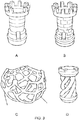
- the chess piece was composed of 657 0.1mm layers and is shown in Figure 3A .
- a glass vessel was loaded with 325g of Genomer 4302, an aliphatic polyester triurethane, manufactured by Rahn AG of Switzerland, 130g of TEDGMA (triethylene dimethacrylate) a reactive diluent manufactured by Sartomer under the trade SR205 to it, 45g of TMPTMA (trimethylolpropane trimethacrylate) a reactive diluent manufactured by Sartomer under the trade SR350.
- the following percentages of bis(.eta.5-2,4-cylcopentadien-1-yl)-bis(2,6-difluoro-3-(1H-pyrrol-1-yl)-phenyl) titanium) were separately added, 0.1%, 0.2%, 0.3%. 0.4%, 0.5%, 0.6%, 0.7%, 0.8%, 0.9%, 1.0%, 1.1%, 1.2%, 1.3%, 1.4% and 1.5%.
- Each composition was mixed at 60 °C for a total of 3 hours and allowed to cool.
- 500g of the light polymerisable compound was composed in the following manner.
- a glass vessel was loaded with 325g of Genomer 4302, an aliphatic polyester triurethane, manufactured by Rahn AG of Switzerland, 130g of TEDGMA (triethylene dimethacrylate) a reactive diluent manufactured by Sartomer under the trade SR205 to it, 41.25g of TMPTMA (trimethylolpropane trimethacrylate) a reactive diluent manufactured by Sartomer under the trade SR350 and 3.75g of (bis(.eta.5-2,4-cylcopentadien-1-yl)-bis(2,6-difluoro-3-(1H-pyrrol-1-yl)-phenyl) titanium) a photoinitiator manufactured by BASF under the trade name Irgacure 784. They were mixed at 60 °C for a total of 3 hours and allowed to cool.
- the LCD screen was a VGA type 4:3 resolution 8" LCD colour monitor with VGA BNC AV Port, manufactured by Samsung. It provided a 800 (horizontal) x 600 pixel resolution (vertical) with a viewing area of 162mm wide by 121.5mm high and a viewing angle of 130 degrees high by 115 degrees vertically. The brightness of the screen was 300cd/sqm.
- a release layer for the LCD screen was created covering it with a suitable curable silicone compound.
- a total of 60g of Silgaurd 184, a 2 part reactive silicone, manufactured by Dow Corporation was mixed thoroughly, de-aerated and poured over the LCD screen to create a low surface energy surface for easy detachment of the polymer from the screen. This provided a 1mm thickness of silicone evenly cured over the screen.
- the screen was left at 40C for 48 hours to fully harden and be dry to touch.
- a flat aluminium platform 75mm x 45mm perforated with holes was mounted to a belt driven motor so that it could be elevated and declined in the vertical plane by increments of 0.1mm.
- a total of 16.9g of the photopolymer was poured in a tray the size of the print platform. It was cured with daylight to form a level solid sheet of exposed polymer. It was not post exposed under water, so the upper surface contained open, not fully cross-linked chains. This sheet was attached to the print platform using 9088 double sided tape manufactured by 3M Corporation.
- An open-topped and open-bottomed polymer containment vat was made from Perspex (trademark of Dupont) to the inner dimensions of the screen. It was sealed around its base to the top of the LCD screen with the same silicone, such that it could contain the liquid polymer in a leak-proof manner. The container was large enough to take the print platform and elevate it to a total of 10cm high.
- the object to be printed was an open lattice of a sphere. It was scaled by a half of its original size so that the final object would be 5cm in diameter, comfortably within the dimensions of the print platform.
- the print platform was then moved 0.5mm away from the screen and the first exposure was started.
- the first exposure was an extended exposure time to ensure that any fine detail is formed and successfully adhered. This first time was set to 2 minutes. After this the normal exposure cycle commenced.
- the print platform was lowered from its previous exposure position by 0.5mm to allow polymer to re-fill the cavity. It was lowered in the motor's fast setting to save time. The motor then stopped and reversed to bring the platform back up to the same position as before, but 0.1mm lower, i.e. a reversal of 0.4mm. The second image was exposed on the screen for 24 seconds, and the process was repeated.
- 500g of the light polymerisable compound was composed in the following manner.
- a glass vessel was loaded with 325g of Genomer 4302, 130g of TEDGMA to it, 40.5g of TMPTMA and 4.5g of titanocene They were mixed at 60°C for a total of 3 hours and allowed to cool.
- the LCD screen was a VGA type 4:3 resolution 8" LCD colour monitor with VGA BNC AV Port. It provided a 800 (horizontal) x 600 pixel resolution (vertical) with a viewing area of 162mm wide by 121.5mm high and a viewing angle of 130 degrees high by 115 degrees vertically. The brightness of the screen was 400cd/sqm.
- An open bottomed rectangular tray of base dimensions 162mm by 121.5mm was constructed from 4mm thick clear cast acrylic sheet, the sheet was 100mm wide, creating the depth of the vat.
- a flat aluminium platform 75mm x 45mm perforated with holes was mounted to a belt driven motor so that it could be elevated and declined in the vertical plane by increments of 0.1mm.
- a total of 500g of the photopolymer was poured into the tray.
- the print platform was lowered down onto the screen and this point was taken as the starting or zero point.
- the object to be printed was a cylindrical spiral shape.
- the print platform was then elevated 0.1mm away from the screen and the first exposure was started.
- the first exposure was an extended exposure time to ensure that any fine detail is formed and successfully adhered. This first time was set to 5 minutes. After this the normal exposure cycle commenced.
- the print platform was raised from its previous exposure position by 0.5mm to allow polymer to re-fill the cavity. It was lowered 0.4mm to leave it 0.1mm away from the screen. The second image was exposed on the screen for 55 seconds, and the process was repeated.
- this daylight polymerisable compound was made by taking 190g of Genomer 4302, an aliphatic polyester triurethane, 135g of Genomer 4269 a urethane acrylate manufactured by Rahn AG of Switzerland, 150g of HDDA (Hexane-1,6-diol diacrylate) a difunctional reactive monomer made by Rahn under the name Miramer M200, adding 22.75g of TMPTMA (trimethylolpropane trimethacrylate) a reactive diluent manufactured by Sartomer under the trade SR350 and 2.25g of (bis(.eta.5-2,4-cylcopentadien-1-yl)-bis(2,6-difluoro-3-(1H-pyrrol-1-yl)-phenyl) titanium) manufactured by BASF under the trade name Irgacure 784. They were all added to a glass mixing vessel and were mixed at 60C
- the LCD screen, 3D printing apparatus and procedure of operation was the same as in Example 3.
- the object to be printed was a scale model of the 101 Tower in Taipei.
- the print platform was moved 0.5mm away from the screen to create a larger first layer to ensure that any fine detail is formed and adhered to the print platform. This first time was set to 90 secs. After this the normal exposure cycle commenced.
- the print platform was lowered from its previous exposure position by 0.5mm to allow polymer to re-fill the cavity. It can be lowered in the motor's fast setting to save time. The motor then stopped and reversed to bring the platform back up to the same position as before but 0.1mm lower, i.e. a reversal of 0.4mm. The second image was exposed on the screen for 15 seconds, and the process was repeated.
- the LCD screen, 3D printing apparatus and procedure of operation was the same as in Example 4.
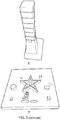
- the object to be printed was a test plate with fine dots and lines.
- the print platform was moved 0.1mm away from the screen to create a larger first layer to ensure that any fine detail is formed and adhered to the print platform. This first time was set to 5 mins. After this the normal exposure cycle commenced.
- the print platform was raised from its previous exposure position by 0.5mm to allow polymer to re-fill the cavity. It was then lowered by 0.45mm, ie a separation of 0.05mm or 50 ⁇ m. The second image was exposed on the screen for 28 seconds, and the process was repeated.
- the LCD screen, 3D printing apparatus and procedure of operation was the same as in Example 4.
- the object to be printed was a tower.
- the print platform was moved 0.5mm away from the screen to create a larger first layer to ensure that any fine detail is formed and adhered to the print platform. This first time was set to 1 minute. After this the normal exposure cycle commenced.
- the print platform was lowered from its previous exposure position by 0.5mm to allow polymer to re-fill the cavity. It can be lowered in the motor's fast setting to save time. The motor then stopped and reversed to bring the platform back up to the same position as before but 0.1mm lower, i.e. a reversal of 0.4mm. The second image was exposed on the screen for 18 seconds, and the process was repeated.
- the LCD screen was a 7" photo display screen made by Lumina. This had a display providing 480 x 234 pixels, a screen size of 15.8cm x 8.7 cm (6.2 inches x 3.4inches) with a viewing angle of 60° vertically and 40° horizontally and a brightness of 200 cd/m 2 .
- the 3D printing apparatus and procedure of operation was the same as in Example 5.
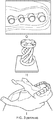
- the object to be printed was a lower human jaw or mandible.
- the print platform was moved 0.5mm away from the screen to create a larger first layer to ensure that any fine detail is formed and adhered to the print platform. This first time was set to 2 minutes. After this the normal exposure cycle commenced.
- the print platform was lowered from its previous exposure position by 0.5mm to allow polymer to re-fill the cavity. It can be lowered in the motor's fast setting to save time. The motor then stopped and reversed to bring the platform back up to the same position as before but 0.1mm lower, i.e. a reversal of 0.4mm. The second image was exposed on the screen for 21 seconds, and the process was repeated.
Landscapes
- Physics & Mathematics (AREA)
- General Physics & Mathematics (AREA)
- Chemical & Material Sciences (AREA)
- Engineering & Computer Science (AREA)
- Materials Engineering (AREA)
- Manufacturing & Machinery (AREA)
- Mechanical Engineering (AREA)
- Optics & Photonics (AREA)
- Inorganic Chemistry (AREA)
- Spectroscopy & Molecular Physics (AREA)
- Health & Medical Sciences (AREA)
- Toxicology (AREA)
Claims (14)
- 3D-Drucker, umfassend:einen visuellen Anzeigebildschirm; wobei höchstens 5 % des vom Bildschirm ausgegebenen Lichts UV-Licht ist;eine Wanne für flüssigen Photopolymer;eine Bauplattform mit einer Bauoberfläche zur Verwendung in der Wanne während des stereolithographischen Druckens eines 3D-Objekts;und ein Betätigungselement zum Variieren des Trennabstands der Bauoberfläche und des visuellen Anzeigebildschirms;wobei der visuelle Anzeigebildschirm während des Druckens eines 3D-Objekts außerhalb der Wanne angeordnet ist undwobei die Wanne mindestens gegenüber einem Teil des Lichtspektrums, der für das menschliche Auge sichtbar ist, transparent ist oder ein Fenster umfasst, das mindestens gegenüber einem Teil des Lichtspektrums, der für das menschliche Auge sichtbar ist, transparent ist.
- 3D-Drucker nach Anspruch 1, umfassend:einen Bildprozessor, der konfiguriert ist, um den visuellen Anzeigebildschirm zu steuern, um eine Abfolge photolithographischer Bilder anzuzeigen;und eine Betätigungssteuerung, die konfiguriert ist, um das Betätigungselement zu steuern;wobei der Bildprozessor und die Betätigungssteuerung konfiguriert sind, um zu kommunizieren, um die Anzeige photolithographischer Bilder und das Variieren des Trennabstands der Bauoberfläche und des visuellen Anzeigebildschirms zu steuern.
- 3D-Drucker nach Anspruch 2, wobei die Betätigungssteuerung konfiguriert ist, um den Trennabstand der Bauoberfläche und des visuellen Anzeigebildschirms zwischen aufeinanderfolgenden stereolithographischen Expositionen um einen Abstand monoton zu erhöhen, der einer Schichtdicke eines zu druckenden 3D-Objekts entspricht.
- 3D-Drucker nach Anspruch 2, wobei die Betätigungssteuerung konfiguriert ist, um den Trennabstand der Bauoberfläche und des visuellen Anzeigebildschirms zwischen aufeinanderfolgenden stereolithographischen Expositionen um einen Abstand zu erhöhen, der größer als eine Schichtdicke eines zu formenden 3D-Objekts ist, und anschließend den Trennabstand um einen zweiten Abstand zu verringern, um eine Nettoerhöhung im Trennabstand bereitzustellen, die einer Schichtdicke eines zu formenden 3D-Objekts entspricht.
- 3D-Drucker nach einem der Ansprüche 1 bis 4, wobei der visuelle Anzeigebildschirm ein Flüssigkristallanzeigebildschirm (Liquid Crystal Display, LCD) ist; optional wobei der visuelle Anzeigebildschirm ein einzelner LCD-Bildschirm ist.
- 3D-Drucker nach Anspruch 5, wobei der visuelle Anzeigebildschirm durch LEDs hintergrundbeleuchtet wird.
- 3D-Drucker nach einem der Ansprüche 1 bis 4, wobei der visuelle Anzeigebildschirm ausgewählt ist aus einem der folgenden Typen: LED (Light Emitting Diode), OLED (Organic Light Emitting Diode), PLED (Polymer Light Emitting Diode), ELD (Electroluminescent Display) und PDP (Plasma Display Panel).
- 3D-Drucker nach einem der Ansprüche 1 bis 7, wobei der visuelle Kristallanzeigebildschirm der Bildschirm eines Geräts ist, ausgewählt aus Fernseher, Computer, Tablet-Computer und Mobiltelefon.
- 3D-Drucker nach einem der Ansprüche 1 bis 8, wobei nichts von dem vom Bildschirm ausgegebenen Licht UV-Licht ist.
- 3D-Drucker nach einem der Ansprüche 1 bis 9, wobei der visuelle Anzeigebildschirm eine Lumineszenz von zwischen 100 bis 2000 Candela pro Quadratmeter hat.
- Verfahren zum Schaffen eines dreidimensionalen Objekts, wobei das Verfahren auf einem 3D-Drucker nach einem der Ansprüche 1 bis 10 ausgeführt wird, wobei das Verfahren umfasst Formen von mehr als zwei Schichten eines ausgehärteten Polymers durch Exponieren von flüssigem Photopolymer gegenüber Licht, das vom visuellen Anzeigebildschirm ausgegeben wird, und wobei das Photopolymer einen Photoinitiator für sichtbares Licht enthält, wobei der Photoinitiator organometallisch oder metallocen ist.
- Verfahren nach einem der Ansprüche 11, wobei der Photoinitiator Titanocen ist.
- Verfahren nach Anspruch 12, wobei der Photoinitiator Bis(.eta.5-2,4-cylcopentadien-1-yl)-bis(2,6-difluor-3-(1H-pyrrol-1-yl)-phenyl)-titan ist.
- Verfahren nach einem der Ansprüche 11 bis 13, wobei mindestens drei angrenzende Schichten des ausgehärteten Polymers nicht übereinandergelagert sind.
Applications Claiming Priority (3)
| Application Number | Priority Date | Filing Date | Title |
|---|---|---|---|
| GBGB1508178.9A GB201508178D0 (en) | 2015-05-13 | 2015-05-13 | Method for making an object |
| GB1513771.4A GB2538333B (en) | 2015-05-13 | 2015-08-04 | Method for making an object |
| PCT/GB2016/051361 WO2016181149A1 (en) | 2015-05-13 | 2016-05-12 | Method for making an object |
Publications (2)
| Publication Number | Publication Date |
|---|---|
| EP3295246A1 EP3295246A1 (de) | 2018-03-21 |
| EP3295246B1 true EP3295246B1 (de) | 2019-05-01 |
Family
ID=53489559
Family Applications (1)
| Application Number | Title | Priority Date | Filing Date |
|---|---|---|---|
| EP16723468.1A Active EP3295246B1 (de) | 2015-05-13 | 2016-05-12 | Verfahren zur herstellung eines objekts |
Country Status (4)
| Country | Link |
|---|---|
| US (2) | US20180141268A1 (de) |
| EP (1) | EP3295246B1 (de) |
| GB (2) | GB201508178D0 (de) |
| WO (1) | WO2016181149A1 (de) |
Families Citing this family (37)
| Publication number | Priority date | Publication date | Assignee | Title |
|---|---|---|---|---|
| WO2015081756A1 (zh) * | 2013-12-03 | 2015-06-11 | 上海普利生机电科技有限公司 | 光固化型3d打印设备及其成像系统 |
| US11919229B2 (en) | 2015-04-16 | 2024-03-05 | Lawrence Livermore National Security, Llc | Large area projection micro stereolithography |
| PL3374163T3 (pl) * | 2015-11-13 | 2023-04-24 | Paxis Llc | Urządzenie, układ i sposób wytwarzania przyrostowego |
| CN120080549A (zh) * | 2016-12-15 | 2025-06-03 | 上海普利生三维科技有限公司 | 光固化型三维打印设备、方法及系统 |
| US11542384B2 (en) | 2017-03-28 | 2023-01-03 | Ford Global Technologies, Llc | Stabilized additive manufacturing articles |
| CN110709471B (zh) * | 2017-06-14 | 2022-04-29 | 科思创德国股份有限公司 | 使用胺用于后固化的增材制造法 |
| EP3645598B1 (de) | 2017-06-30 | 2024-06-19 | Stratasys, Inc. | Additives herstellungsverfahren mit einem thermoplastischen radikalisch vernetzbaren aufbaumaterial |
| US12472685B2 (en) * | 2018-01-12 | 2025-11-18 | University Of Florida Research Foundation, Incorporated | Three-dimensional fabrication at inert immiscible liquid interface |
| CA3096390C (en) | 2018-04-06 | 2023-10-17 | Paxis Llc | Additive manufacturing apparatus, system, and method |
| GB201808384D0 (en) | 2018-05-22 | 2018-07-11 | Photocentric Ltd | Methods for making a metal, sand or ceramic object by additive manufacture and formulations for use in said methods |
| GB201815653D0 (en) | 2018-09-26 | 2018-11-07 | Photocentric Ltd | Method of automating the manufacture of 3D printed objects |
| CA3116709A1 (en) | 2018-10-17 | 2020-04-23 | Inkbit, LLC | Thiol-ene printable resins for inkjet 3d printing |
| WO2020123479A1 (en) * | 2018-12-10 | 2020-06-18 | Inkbit, LLC | Precision system for additive fabrication |
| CN109795113B (zh) * | 2019-02-20 | 2021-06-08 | 广州黑格智造信息科技有限公司 | 3d打印机及三维模型打印方法 |
| GB201902878D0 (en) * | 2019-03-04 | 2019-04-17 | Photocentric Ltd | Method of making a 3D printed dental aligener or mouthgaurd |
| CN110039780B (zh) * | 2019-05-24 | 2024-05-10 | 杭州捷诺飞生物科技股份有限公司 | 3d打印器皿、置物台及3d打印机 |
| FR3096606A1 (fr) | 2019-05-29 | 2020-12-04 | Elkem Silicones France Sas | Méthode de fabrication additive pour produire un article en élastomère silicone |
| EP3819100B1 (de) * | 2019-11-08 | 2021-08-11 | Ivoclar Vivadent AG | Verfahren zum generativen aufbau von formkörpern durch stereolithographie |
| WO2021173651A1 (en) | 2020-02-26 | 2021-09-02 | Jabil, Inc. | Chain scission to make improved polymers for 3d printing |
| WO2021183340A1 (en) | 2020-03-10 | 2021-09-16 | Sirrus, Inc. | Radiation cured copolymers of dicarbonyl substituted-l-alkenes and electron rich comonomers |
| JP7796661B2 (ja) | 2020-03-25 | 2026-01-09 | オーピーティー インダストリーズ,インコーポレイテッド | マイクロ構造の3d印刷のためのシステム、方法及びファイルフォーマット |
| WO2021231288A1 (en) | 2020-05-15 | 2021-11-18 | Nippon Shokubai Co., Ltd. | Improved dicarbonyl substituted-1-alkene compositions |
| WO2021252740A1 (en) | 2020-06-10 | 2021-12-16 | Inkbit, LLC | Materials for photoinitiated cationic ring-opening polymerization and uses thereof |
| WO2022005947A1 (en) | 2020-06-29 | 2022-01-06 | Board Of Regents, The University Of Texas System | Photocurable compositions and methods of use thereof |
| US12358222B2 (en) | 2020-08-14 | 2025-07-15 | Paxis Llc | Additive manufacturing apparatus, system, and method |
| EP4330016A4 (de) * | 2021-04-26 | 2025-02-26 | 3D Systems, Inc. | Systeme und verfahren zur durchführung einer optisch kalibrierten grossflächigen mikrostereolithographie |
| CA3215376A1 (en) | 2021-04-26 | 2022-11-03 | Bryan D. Moran | Methods of calibration of a stereolithography system |
| US20220380549A1 (en) | 2021-05-12 | 2022-12-01 | Elkem Silicones USA Corp. | Method for producing a three-dimensional printed article |
| US11964425B2 (en) | 2021-05-12 | 2024-04-23 | Elkem Silicones USA Corp. | Method for producing a three-dimensional printed article |
| US12427719B1 (en) | 2021-07-27 | 2025-09-30 | Antonio St. Clair Lloyd Williams | Digital manufacturing device operable in additive or subtractive manufacturing modes using selectable materials |
| WO2023123326A1 (en) | 2021-12-31 | 2023-07-06 | Elkem Silicones Shanghai Co., Ltd. | Silicone composition and a method for photopolymerization-based 3d printing |
| US20260109820A1 (en) | 2022-09-15 | 2026-04-23 | Elkem Silicones France Sas | Additive manufacturing method for producing a silicone elastomer article |
| US12605889B2 (en) | 2022-09-22 | 2026-04-21 | Align Technology, Inc. | Modular build platforms for additive manufacturing |
| EP4344873A1 (de) | 2022-09-27 | 2024-04-03 | Elkem Silicones France SAS | Nachbehandlung eines 3d-gedruckten elastomersilikonartikels |
| WO2024141095A1 (en) | 2022-12-30 | 2024-07-04 | Elkem Silicones Shanghai Co., Ltd. | Method for manufacturing 3d printed article using a photocurable silicone composition |
| FR3145164A1 (fr) | 2023-01-20 | 2024-07-26 | Elkem Silicones France Sas | Méthode de fabrication additive pour produire un article en élastomère silicone |
| WO2024200927A1 (fr) | 2023-03-31 | 2024-10-03 | Elkem Silicones France Sas | Procédé de préparation d'organopolysiloxanes à fonctions (méth)acrylates |
Family Cites Families (11)
| Publication number | Priority date | Publication date | Assignee | Title |
|---|---|---|---|---|
| WO1995015841A1 (fr) * | 1992-06-05 | 1995-06-15 | Finab Limited | Machine de fabrication d'objets par photopolymerisation selective de liquides ou poudres par couches |
| US7088432B2 (en) * | 2000-09-27 | 2006-08-08 | The Regents Of The University Of California | Dynamic mask projection stereo micro lithography |
| US6764796B2 (en) * | 2001-06-27 | 2004-07-20 | University Of South Florida | Maskless photolithography using plasma displays |
| US7232850B2 (en) * | 2003-10-03 | 2007-06-19 | Huntsman Advanced Materials Americas Inc. | Photocurable compositions for articles having stable tensile properties |
| EP1709099A2 (de) * | 2004-01-27 | 2006-10-11 | Ciba Specialty Chemicals Holding Inc. | Thermisch stabile kationische photohärtbare zusammensetzungen |
| US7268172B2 (en) * | 2004-10-15 | 2007-09-11 | Bayer Materialscience Llc | Radiation curable compositions |
| GB0610606D0 (en) * | 2006-05-30 | 2006-07-05 | Photocentric Ltd | Process and apparatus |
| KR20100014901A (ko) * | 2007-03-14 | 2010-02-11 | 훈츠만 어드밴스트 머티리얼스(스위처랜드) 게엠베하 | Abs-유사 물품을 제조하기 위한 광경화성 조성물 |
| EP2218571A1 (de) * | 2009-01-30 | 2010-08-18 | Nederlandse Organisatie voor toegepast -natuurwetenschappelijk onderzoek TNO | Beleuchtungssystem zur Verwendung in einer Stereolithographievorrichtung |
| US20120251841A1 (en) * | 2009-12-17 | 2012-10-04 | Dsm Ip Assets, B.V. | Liquid radiation curable resins for additive fabrication comprising a triaryl sulfonium borate cationic photoinitiator |
| EP2502728B1 (de) * | 2011-03-23 | 2017-01-04 | DSM IP Assets B.V. | Leichte und hochfeste, mittels Additivherstellungsverfahren erzeugbare dreidimensionale Artikel |
-
2015
- 2015-05-13 GB GBGB1508178.9A patent/GB201508178D0/en not_active Ceased
- 2015-08-04 GB GB1513771.4A patent/GB2538333B/en active Active
-
2016
- 2016-05-12 WO PCT/GB2016/051361 patent/WO2016181149A1/en not_active Ceased
- 2016-05-12 EP EP16723468.1A patent/EP3295246B1/de active Active
- 2016-05-12 US US15/572,822 patent/US20180141268A1/en not_active Abandoned
-
2021
- 2021-03-01 US US17/188,487 patent/US20210197447A1/en not_active Abandoned
Also Published As
| Publication number | Publication date |
|---|---|
| EP3295246A1 (de) | 2018-03-21 |
| WO2016181149A1 (en) | 2016-11-17 |
| US20180141268A1 (en) | 2018-05-24 |
| GB2538333B (en) | 2017-12-06 |
| GB201513771D0 (en) | 2015-09-16 |
| US20210197447A1 (en) | 2021-07-01 |
| GB2538333A (en) | 2016-11-16 |
| GB201508178D0 (en) | 2015-06-24 |
Similar Documents
| Publication | Publication Date | Title |
|---|---|---|
| US20210197447A1 (en) | Method for Making an Object | |
| US11117316B2 (en) | Continuous liquid interface production with upconversion photopolymerization | |
| US12179435B2 (en) | Methods of producing three-dimensional objects with apparatus having feed channels | |
| EP3705077B1 (de) | Verfahren zur herstellung eines 3d-gedruckten zahnärztlichen ausrichters oder mundschutzes | |
| US11597839B2 (en) | Methods for making an object and formulations for use in said methods | |
| US20180243976A1 (en) | Method and Apparatus for Producing Three- Dimensional Objects | |
| EP3815879B1 (de) | Verfahren zum 3d-drucken in einer kammer mit einstellbarem volumen unter verwendung von lcd-bildschirmen als verfahren zur polymerisation | |
| US11097467B2 (en) | Method of automating the manufacture of 3D printed objects | |
| JP2020121569A (ja) | 付加製造装置及び方法 | |
| WO2007138356A1 (en) | Maskless photopolymer exposure process and apparatus | |
| EP3181357A1 (de) | Additives fertigungsverfahren mit dynamischer lichtprojektion für flexografiedruckvorlage | |
| US20060161287A1 (en) | Rapid prototyping and manufacturing of photocured objects using LCD panel as programmably variable photomask | |
| CN116373295A (zh) | 3d打印设备、打印方法、打印系统及存储介质 | |
| JP2024517720A (ja) | 大面積マイクロステレオリソグラフィにおけるレイヤレベリングのためのシステム及び方法 | |
| JPH07329191A (ja) | 光造形法 | |
| US11370165B2 (en) | Method for improving resolution in LCD screen based 3D printers | |
| CN106313568A (zh) | 底投影光固化成型中将实体造型与树脂槽分离的控制方法 | |
| RU2810712C1 (ru) | Способ векторно-матричной фотополимерной 3Д-печати (варианты) | |
| JPH0669725B2 (ja) | 立体形状の形成方法 |
Legal Events
| Date | Code | Title | Description |
|---|---|---|---|
| STAA | Information on the status of an ep patent application or granted ep patent |
Free format text: STATUS: THE INTERNATIONAL PUBLICATION HAS BEEN MADE |
|
| PUAI | Public reference made under article 153(3) epc to a published international application that has entered the european phase |
Free format text: ORIGINAL CODE: 0009012 |
|
| STAA | Information on the status of an ep patent application or granted ep patent |
Free format text: STATUS: REQUEST FOR EXAMINATION WAS MADE |
|
| 17P | Request for examination filed |
Effective date: 20171107 |
|
| AK | Designated contracting states |
Kind code of ref document: A1 Designated state(s): AL AT BE BG CH CY CZ DE DK EE ES FI FR GB GR HR HU IE IS IT LI LT LU LV MC MK MT NL NO PL PT RO RS SE SI SK SM TR |
|
| AX | Request for extension of the european patent |
Extension state: BA ME |
|
| DAV | Request for validation of the european patent (deleted) | ||
| DAX | Request for extension of the european patent (deleted) | ||
| GRAP | Despatch of communication of intention to grant a patent |
Free format text: ORIGINAL CODE: EPIDOSNIGR1 |
|
| STAA | Information on the status of an ep patent application or granted ep patent |
Free format text: STATUS: GRANT OF PATENT IS INTENDED |
|
| INTG | Intention to grant announced |
Effective date: 20181211 |
|
| GRAS | Grant fee paid |
Free format text: ORIGINAL CODE: EPIDOSNIGR3 |
|
| GRAA | (expected) grant |
Free format text: ORIGINAL CODE: 0009210 |
|
| STAA | Information on the status of an ep patent application or granted ep patent |
Free format text: STATUS: THE PATENT HAS BEEN GRANTED |
|
| AK | Designated contracting states |
Kind code of ref document: B1 Designated state(s): AL AT BE BG CH CY CZ DE DK EE ES FI FR GB GR HR HU IE IS IT LI LT LU LV MC MK MT NL NO PL PT RO RS SE SI SK SM TR |
|
| REG | Reference to a national code |
Ref country code: GB Ref legal event code: FG4D |
|
| REG | Reference to a national code |
Ref country code: CH Ref legal event code: EP Ref country code: AT Ref legal event code: REF Ref document number: 1127728 Country of ref document: AT Kind code of ref document: T Effective date: 20190515 |
|
| REG | Reference to a national code |
Ref country code: DE Ref legal event code: R096 Ref document number: 602016013237 Country of ref document: DE |
|
| REG | Reference to a national code |
Ref country code: IE Ref legal event code: FG4D |
|
| REG | Reference to a national code |
Ref country code: CH Ref legal event code: NV Representative=s name: MICHELI AND CIE SA, CH |
|
| REG | Reference to a national code |
Ref country code: NL Ref legal event code: MP Effective date: 20190501 |
|
| REG | Reference to a national code |
Ref country code: LT Ref legal event code: MG4D |
|
| PG25 | Lapsed in a contracting state [announced via postgrant information from national office to epo] |
Ref country code: PT Free format text: LAPSE BECAUSE OF FAILURE TO SUBMIT A TRANSLATION OF THE DESCRIPTION OR TO PAY THE FEE WITHIN THE PRESCRIBED TIME-LIMIT Effective date: 20190901 Ref country code: ES Free format text: LAPSE BECAUSE OF FAILURE TO SUBMIT A TRANSLATION OF THE DESCRIPTION OR TO PAY THE FEE WITHIN THE PRESCRIBED TIME-LIMIT Effective date: 20190501 Ref country code: LT Free format text: LAPSE BECAUSE OF FAILURE TO SUBMIT A TRANSLATION OF THE DESCRIPTION OR TO PAY THE FEE WITHIN THE PRESCRIBED TIME-LIMIT Effective date: 20190501 Ref country code: NL Free format text: LAPSE BECAUSE OF FAILURE TO SUBMIT A TRANSLATION OF THE DESCRIPTION OR TO PAY THE FEE WITHIN THE PRESCRIBED TIME-LIMIT Effective date: 20190501 Ref country code: NO Free format text: LAPSE BECAUSE OF FAILURE TO SUBMIT A TRANSLATION OF THE DESCRIPTION OR TO PAY THE FEE WITHIN THE PRESCRIBED TIME-LIMIT Effective date: 20190801 Ref country code: FI Free format text: LAPSE BECAUSE OF FAILURE TO SUBMIT A TRANSLATION OF THE DESCRIPTION OR TO PAY THE FEE WITHIN THE PRESCRIBED TIME-LIMIT Effective date: 20190501 Ref country code: HR Free format text: LAPSE BECAUSE OF FAILURE TO SUBMIT A TRANSLATION OF THE DESCRIPTION OR TO PAY THE FEE WITHIN THE PRESCRIBED TIME-LIMIT Effective date: 20190501 Ref country code: SE Free format text: LAPSE BECAUSE OF FAILURE TO SUBMIT A TRANSLATION OF THE DESCRIPTION OR TO PAY THE FEE WITHIN THE PRESCRIBED TIME-LIMIT Effective date: 20190501 Ref country code: AL Free format text: LAPSE BECAUSE OF FAILURE TO SUBMIT A TRANSLATION OF THE DESCRIPTION OR TO PAY THE FEE WITHIN THE PRESCRIBED TIME-LIMIT Effective date: 20190501 |
|
| PG25 | Lapsed in a contracting state [announced via postgrant information from national office to epo] |
Ref country code: RS Free format text: LAPSE BECAUSE OF FAILURE TO SUBMIT A TRANSLATION OF THE DESCRIPTION OR TO PAY THE FEE WITHIN THE PRESCRIBED TIME-LIMIT Effective date: 20190501 Ref country code: LV Free format text: LAPSE BECAUSE OF FAILURE TO SUBMIT A TRANSLATION OF THE DESCRIPTION OR TO PAY THE FEE WITHIN THE PRESCRIBED TIME-LIMIT Effective date: 20190501 Ref country code: GR Free format text: LAPSE BECAUSE OF FAILURE TO SUBMIT A TRANSLATION OF THE DESCRIPTION OR TO PAY THE FEE WITHIN THE PRESCRIBED TIME-LIMIT Effective date: 20190802 Ref country code: BG Free format text: LAPSE BECAUSE OF FAILURE TO SUBMIT A TRANSLATION OF THE DESCRIPTION OR TO PAY THE FEE WITHIN THE PRESCRIBED TIME-LIMIT Effective date: 20190801 |
|
| REG | Reference to a national code |
Ref country code: AT Ref legal event code: MK05 Ref document number: 1127728 Country of ref document: AT Kind code of ref document: T Effective date: 20190501 |
|
| PG25 | Lapsed in a contracting state [announced via postgrant information from national office to epo] |
Ref country code: IS Free format text: LAPSE BECAUSE OF FAILURE TO SUBMIT A TRANSLATION OF THE DESCRIPTION OR TO PAY THE FEE WITHIN THE PRESCRIBED TIME-LIMIT Effective date: 20190901 |
|
| PG25 | Lapsed in a contracting state [announced via postgrant information from national office to epo] |
Ref country code: AT Free format text: LAPSE BECAUSE OF FAILURE TO SUBMIT A TRANSLATION OF THE DESCRIPTION OR TO PAY THE FEE WITHIN THE PRESCRIBED TIME-LIMIT Effective date: 20190501 Ref country code: MC Free format text: LAPSE BECAUSE OF FAILURE TO SUBMIT A TRANSLATION OF THE DESCRIPTION OR TO PAY THE FEE WITHIN THE PRESCRIBED TIME-LIMIT Effective date: 20190501 Ref country code: CZ Free format text: LAPSE BECAUSE OF FAILURE TO SUBMIT A TRANSLATION OF THE DESCRIPTION OR TO PAY THE FEE WITHIN THE PRESCRIBED TIME-LIMIT Effective date: 20190501 Ref country code: SK Free format text: LAPSE BECAUSE OF FAILURE TO SUBMIT A TRANSLATION OF THE DESCRIPTION OR TO PAY THE FEE WITHIN THE PRESCRIBED TIME-LIMIT Effective date: 20190501 Ref country code: RO Free format text: LAPSE BECAUSE OF FAILURE TO SUBMIT A TRANSLATION OF THE DESCRIPTION OR TO PAY THE FEE WITHIN THE PRESCRIBED TIME-LIMIT Effective date: 20190501 Ref country code: EE Free format text: LAPSE BECAUSE OF FAILURE TO SUBMIT A TRANSLATION OF THE DESCRIPTION OR TO PAY THE FEE WITHIN THE PRESCRIBED TIME-LIMIT Effective date: 20190501 Ref country code: DK Free format text: LAPSE BECAUSE OF FAILURE TO SUBMIT A TRANSLATION OF THE DESCRIPTION OR TO PAY THE FEE WITHIN THE PRESCRIBED TIME-LIMIT Effective date: 20190501 |
|
| REG | Reference to a national code |
Ref country code: DE Ref legal event code: R097 Ref document number: 602016013237 Country of ref document: DE |
|
| REG | Reference to a national code |
Ref country code: BE Ref legal event code: MM Effective date: 20190531 |
|
| PG25 | Lapsed in a contracting state [announced via postgrant information from national office to epo] |
Ref country code: LU Free format text: LAPSE BECAUSE OF NON-PAYMENT OF DUE FEES Effective date: 20190512 Ref country code: SM Free format text: LAPSE BECAUSE OF FAILURE TO SUBMIT A TRANSLATION OF THE DESCRIPTION OR TO PAY THE FEE WITHIN THE PRESCRIBED TIME-LIMIT Effective date: 20190501 Ref country code: IT Free format text: LAPSE BECAUSE OF FAILURE TO SUBMIT A TRANSLATION OF THE DESCRIPTION OR TO PAY THE FEE WITHIN THE PRESCRIBED TIME-LIMIT Effective date: 20190501 |
|
| PLBE | No opposition filed within time limit |
Free format text: ORIGINAL CODE: 0009261 |
|
| STAA | Information on the status of an ep patent application or granted ep patent |
Free format text: STATUS: NO OPPOSITION FILED WITHIN TIME LIMIT |
|
| PG25 | Lapsed in a contracting state [announced via postgrant information from national office to epo] |
Ref country code: TR Free format text: LAPSE BECAUSE OF FAILURE TO SUBMIT A TRANSLATION OF THE DESCRIPTION OR TO PAY THE FEE WITHIN THE PRESCRIBED TIME-LIMIT Effective date: 20190501 |
|
| 26N | No opposition filed |
Effective date: 20200204 |
|
| PG25 | Lapsed in a contracting state [announced via postgrant information from national office to epo] |
Ref country code: PL Free format text: LAPSE BECAUSE OF FAILURE TO SUBMIT A TRANSLATION OF THE DESCRIPTION OR TO PAY THE FEE WITHIN THE PRESCRIBED TIME-LIMIT Effective date: 20190501 Ref country code: IE Free format text: LAPSE BECAUSE OF NON-PAYMENT OF DUE FEES Effective date: 20190512 |
|
| PG25 | Lapsed in a contracting state [announced via postgrant information from national office to epo] |
Ref country code: BE Free format text: LAPSE BECAUSE OF NON-PAYMENT OF DUE FEES Effective date: 20190531 Ref country code: SI Free format text: LAPSE BECAUSE OF FAILURE TO SUBMIT A TRANSLATION OF THE DESCRIPTION OR TO PAY THE FEE WITHIN THE PRESCRIBED TIME-LIMIT Effective date: 20190501 |
|
| PG25 | Lapsed in a contracting state [announced via postgrant information from national office to epo] |
Ref country code: CY Free format text: LAPSE BECAUSE OF FAILURE TO SUBMIT A TRANSLATION OF THE DESCRIPTION OR TO PAY THE FEE WITHIN THE PRESCRIBED TIME-LIMIT Effective date: 20190501 |
|
| PG25 | Lapsed in a contracting state [announced via postgrant information from national office to epo] |
Ref country code: HU Free format text: LAPSE BECAUSE OF FAILURE TO SUBMIT A TRANSLATION OF THE DESCRIPTION OR TO PAY THE FEE WITHIN THE PRESCRIBED TIME-LIMIT; INVALID AB INITIO Effective date: 20160512 Ref country code: MT Free format text: LAPSE BECAUSE OF FAILURE TO SUBMIT A TRANSLATION OF THE DESCRIPTION OR TO PAY THE FEE WITHIN THE PRESCRIBED TIME-LIMIT Effective date: 20190501 |
|
| PG25 | Lapsed in a contracting state [announced via postgrant information from national office to epo] |
Ref country code: MK Free format text: LAPSE BECAUSE OF FAILURE TO SUBMIT A TRANSLATION OF THE DESCRIPTION OR TO PAY THE FEE WITHIN THE PRESCRIBED TIME-LIMIT Effective date: 20190501 |
|
| PGFP | Annual fee paid to national office [announced via postgrant information from national office to epo] |
Ref country code: FR Payment date: 20220513 Year of fee payment: 7 |
|
| PGFP | Annual fee paid to national office [announced via postgrant information from national office to epo] |
Ref country code: CH Payment date: 20220531 Year of fee payment: 7 |
|
| PGFP | Annual fee paid to national office [announced via postgrant information from national office to epo] |
Ref country code: DE Payment date: 20230426 Year of fee payment: 8 |
|
| REG | Reference to a national code |
Ref country code: CH Ref legal event code: PL |
|
| PG25 | Lapsed in a contracting state [announced via postgrant information from national office to epo] |
Ref country code: LI Free format text: LAPSE BECAUSE OF NON-PAYMENT OF DUE FEES Effective date: 20230531 Ref country code: CH Free format text: LAPSE BECAUSE OF NON-PAYMENT OF DUE FEES Effective date: 20230531 |
|
| PG25 | Lapsed in a contracting state [announced via postgrant information from national office to epo] |
Ref country code: FR Free format text: LAPSE BECAUSE OF NON-PAYMENT OF DUE FEES Effective date: 20230531 |
|
| REG | Reference to a national code |
Ref country code: DE Ref legal event code: R119 Ref document number: 602016013237 Country of ref document: DE |
|
| PG25 | Lapsed in a contracting state [announced via postgrant information from national office to epo] |
Ref country code: DE Free format text: LAPSE BECAUSE OF NON-PAYMENT OF DUE FEES Effective date: 20241203 |
|
| PGFP | Annual fee paid to national office [announced via postgrant information from national office to epo] |
Ref country code: GB Payment date: 20260331 Year of fee payment: 11 |