EP3294223B1 - Expandierbare lordose-bandscheibenimplantate - Google Patents
Expandierbare lordose-bandscheibenimplantate Download PDFInfo
- Publication number
- EP3294223B1 EP3294223B1 EP16724244.5A EP16724244A EP3294223B1 EP 3294223 B1 EP3294223 B1 EP 3294223B1 EP 16724244 A EP16724244 A EP 16724244A EP 3294223 B1 EP3294223 B1 EP 3294223B1
- Authority
- EP
- European Patent Office
- Prior art keywords
- bottom plate
- chassis
- implant
- top plate
- screw
- Prior art date
- Legal status (The legal status is an assumption and is not a legal conclusion. Google has not performed a legal analysis and makes no representation as to the accuracy of the status listed.)
- Active
Links
Images






Classifications
-
- A—HUMAN NECESSITIES
- A61—MEDICAL OR VETERINARY SCIENCE; HYGIENE
- A61F—FILTERS IMPLANTABLE INTO BLOOD VESSELS; PROSTHESES; DEVICES PROVIDING PATENCY TO, OR PREVENTING COLLAPSING OF, TUBULAR STRUCTURES OF THE BODY, e.g. STENTS; ORTHOPAEDIC, NURSING OR CONTRACEPTIVE DEVICES; FOMENTATION; TREATMENT OR PROTECTION OF EYES OR EARS; BANDAGES, DRESSINGS OR ABSORBENT PADS; FIRST-AID KITS
- A61F2/00—Filters implantable into blood vessels; Prostheses, i.e. artificial substitutes or replacements for parts of the body; Appliances for connecting them with the body; Devices providing patency to, or preventing collapsing of, tubular structures of the body, e.g. stents
- A61F2/02—Prostheses implantable into the body
- A61F2/30—Joints
- A61F2/44—Joints for the spine, e.g. vertebrae, spinal discs
- A61F2/4455—Joints for the spine, e.g. vertebrae, spinal discs for the fusion of spinal bodies, e.g. intervertebral fusion of adjacent spinal bodies, e.g. fusion cages
- A61F2/447—Joints for the spine, e.g. vertebrae, spinal discs for the fusion of spinal bodies, e.g. intervertebral fusion of adjacent spinal bodies, e.g. fusion cages substantially parallelepipedal, e.g. having a rectangular or trapezoidal cross-section
-
- A—HUMAN NECESSITIES
- A61—MEDICAL OR VETERINARY SCIENCE; HYGIENE
- A61F—FILTERS IMPLANTABLE INTO BLOOD VESSELS; PROSTHESES; DEVICES PROVIDING PATENCY TO, OR PREVENTING COLLAPSING OF, TUBULAR STRUCTURES OF THE BODY, e.g. STENTS; ORTHOPAEDIC, NURSING OR CONTRACEPTIVE DEVICES; FOMENTATION; TREATMENT OR PROTECTION OF EYES OR EARS; BANDAGES, DRESSINGS OR ABSORBENT PADS; FIRST-AID KITS
- A61F2/00—Filters implantable into blood vessels; Prostheses, i.e. artificial substitutes or replacements for parts of the body; Appliances for connecting them with the body; Devices providing patency to, or preventing collapsing of, tubular structures of the body, e.g. stents
- A61F2/02—Prostheses implantable into the body
- A61F2/30—Joints
- A61F2/44—Joints for the spine, e.g. vertebrae, spinal discs
- A61F2/4455—Joints for the spine, e.g. vertebrae, spinal discs for the fusion of spinal bodies, e.g. intervertebral fusion of adjacent spinal bodies, e.g. fusion cages
-
- A—HUMAN NECESSITIES
- A61—MEDICAL OR VETERINARY SCIENCE; HYGIENE
- A61F—FILTERS IMPLANTABLE INTO BLOOD VESSELS; PROSTHESES; DEVICES PROVIDING PATENCY TO, OR PREVENTING COLLAPSING OF, TUBULAR STRUCTURES OF THE BODY, e.g. STENTS; ORTHOPAEDIC, NURSING OR CONTRACEPTIVE DEVICES; FOMENTATION; TREATMENT OR PROTECTION OF EYES OR EARS; BANDAGES, DRESSINGS OR ABSORBENT PADS; FIRST-AID KITS
- A61F2/00—Filters implantable into blood vessels; Prostheses, i.e. artificial substitutes or replacements for parts of the body; Appliances for connecting them with the body; Devices providing patency to, or preventing collapsing of, tubular structures of the body, e.g. stents
- A61F2/02—Prostheses implantable into the body
- A61F2/30—Joints
- A61F2002/30001—Additional features of subject-matter classified in A61F2/28, A61F2/30 and subgroups thereof
- A61F2002/30316—The prosthesis having different structural features at different locations within the same prosthesis; Connections between prosthetic parts; Special structural features of bone or joint prostheses not otherwise provided for
- A61F2002/30329—Connections or couplings between prosthetic parts, e.g. between modular parts; Connecting elements
- A61F2002/30331—Connections or couplings between prosthetic parts, e.g. between modular parts; Connecting elements made by longitudinally pushing a protrusion into a complementarily-shaped recess, e.g. held by friction fit
-
- A—HUMAN NECESSITIES
- A61—MEDICAL OR VETERINARY SCIENCE; HYGIENE
- A61F—FILTERS IMPLANTABLE INTO BLOOD VESSELS; PROSTHESES; DEVICES PROVIDING PATENCY TO, OR PREVENTING COLLAPSING OF, TUBULAR STRUCTURES OF THE BODY, e.g. STENTS; ORTHOPAEDIC, NURSING OR CONTRACEPTIVE DEVICES; FOMENTATION; TREATMENT OR PROTECTION OF EYES OR EARS; BANDAGES, DRESSINGS OR ABSORBENT PADS; FIRST-AID KITS
- A61F2/00—Filters implantable into blood vessels; Prostheses, i.e. artificial substitutes or replacements for parts of the body; Appliances for connecting them with the body; Devices providing patency to, or preventing collapsing of, tubular structures of the body, e.g. stents
- A61F2/02—Prostheses implantable into the body
- A61F2/30—Joints
- A61F2002/30001—Additional features of subject-matter classified in A61F2/28, A61F2/30 and subgroups thereof
- A61F2002/30316—The prosthesis having different structural features at different locations within the same prosthesis; Connections between prosthetic parts; Special structural features of bone or joint prostheses not otherwise provided for
- A61F2002/30329—Connections or couplings between prosthetic parts, e.g. between modular parts; Connecting elements
- A61F2002/30383—Connections or couplings between prosthetic parts, e.g. between modular parts; Connecting elements made by laterally inserting a protrusion, e.g. a rib into a complementarily-shaped groove
-
- A—HUMAN NECESSITIES
- A61—MEDICAL OR VETERINARY SCIENCE; HYGIENE
- A61F—FILTERS IMPLANTABLE INTO BLOOD VESSELS; PROSTHESES; DEVICES PROVIDING PATENCY TO, OR PREVENTING COLLAPSING OF, TUBULAR STRUCTURES OF THE BODY, e.g. STENTS; ORTHOPAEDIC, NURSING OR CONTRACEPTIVE DEVICES; FOMENTATION; TREATMENT OR PROTECTION OF EYES OR EARS; BANDAGES, DRESSINGS OR ABSORBENT PADS; FIRST-AID KITS
- A61F2/00—Filters implantable into blood vessels; Prostheses, i.e. artificial substitutes or replacements for parts of the body; Appliances for connecting them with the body; Devices providing patency to, or preventing collapsing of, tubular structures of the body, e.g. stents
- A61F2/02—Prostheses implantable into the body
- A61F2/30—Joints
- A61F2002/30001—Additional features of subject-matter classified in A61F2/28, A61F2/30 and subgroups thereof
- A61F2002/30316—The prosthesis having different structural features at different locations within the same prosthesis; Connections between prosthetic parts; Special structural features of bone or joint prostheses not otherwise provided for
- A61F2002/30329—Connections or couplings between prosthetic parts, e.g. between modular parts; Connecting elements
- A61F2002/30405—Connections or couplings between prosthetic parts, e.g. between modular parts; Connecting elements made by screwing complementary threads machined on the parts themselves
-
- A—HUMAN NECESSITIES
- A61—MEDICAL OR VETERINARY SCIENCE; HYGIENE
- A61F—FILTERS IMPLANTABLE INTO BLOOD VESSELS; PROSTHESES; DEVICES PROVIDING PATENCY TO, OR PREVENTING COLLAPSING OF, TUBULAR STRUCTURES OF THE BODY, e.g. STENTS; ORTHOPAEDIC, NURSING OR CONTRACEPTIVE DEVICES; FOMENTATION; TREATMENT OR PROTECTION OF EYES OR EARS; BANDAGES, DRESSINGS OR ABSORBENT PADS; FIRST-AID KITS
- A61F2/00—Filters implantable into blood vessels; Prostheses, i.e. artificial substitutes or replacements for parts of the body; Appliances for connecting them with the body; Devices providing patency to, or preventing collapsing of, tubular structures of the body, e.g. stents
- A61F2/02—Prostheses implantable into the body
- A61F2/30—Joints
- A61F2002/30001—Additional features of subject-matter classified in A61F2/28, A61F2/30 and subgroups thereof
- A61F2002/30316—The prosthesis having different structural features at different locations within the same prosthesis; Connections between prosthetic parts; Special structural features of bone or joint prostheses not otherwise provided for
- A61F2002/30329—Connections or couplings between prosthetic parts, e.g. between modular parts; Connecting elements
- A61F2002/30433—Connections or couplings between prosthetic parts, e.g. between modular parts; Connecting elements using additional screws, bolts, dowels, rivets or washers e.g. connecting screws
-
- A—HUMAN NECESSITIES
- A61—MEDICAL OR VETERINARY SCIENCE; HYGIENE
- A61F—FILTERS IMPLANTABLE INTO BLOOD VESSELS; PROSTHESES; DEVICES PROVIDING PATENCY TO, OR PREVENTING COLLAPSING OF, TUBULAR STRUCTURES OF THE BODY, e.g. STENTS; ORTHOPAEDIC, NURSING OR CONTRACEPTIVE DEVICES; FOMENTATION; TREATMENT OR PROTECTION OF EYES OR EARS; BANDAGES, DRESSINGS OR ABSORBENT PADS; FIRST-AID KITS
- A61F2/00—Filters implantable into blood vessels; Prostheses, i.e. artificial substitutes or replacements for parts of the body; Appliances for connecting them with the body; Devices providing patency to, or preventing collapsing of, tubular structures of the body, e.g. stents
- A61F2/02—Prostheses implantable into the body
- A61F2/30—Joints
- A61F2002/30001—Additional features of subject-matter classified in A61F2/28, A61F2/30 and subgroups thereof
- A61F2002/30316—The prosthesis having different structural features at different locations within the same prosthesis; Connections between prosthetic parts; Special structural features of bone or joint prostheses not otherwise provided for
- A61F2002/30329—Connections or couplings between prosthetic parts, e.g. between modular parts; Connecting elements
- A61F2002/30471—Connections or couplings between prosthetic parts, e.g. between modular parts; Connecting elements connected by a hinged linkage mechanism, e.g. of the single-bar or multi-bar linkage type
-
- A—HUMAN NECESSITIES
- A61—MEDICAL OR VETERINARY SCIENCE; HYGIENE
- A61F—FILTERS IMPLANTABLE INTO BLOOD VESSELS; PROSTHESES; DEVICES PROVIDING PATENCY TO, OR PREVENTING COLLAPSING OF, TUBULAR STRUCTURES OF THE BODY, e.g. STENTS; ORTHOPAEDIC, NURSING OR CONTRACEPTIVE DEVICES; FOMENTATION; TREATMENT OR PROTECTION OF EYES OR EARS; BANDAGES, DRESSINGS OR ABSORBENT PADS; FIRST-AID KITS
- A61F2/00—Filters implantable into blood vessels; Prostheses, i.e. artificial substitutes or replacements for parts of the body; Appliances for connecting them with the body; Devices providing patency to, or preventing collapsing of, tubular structures of the body, e.g. stents
- A61F2/02—Prostheses implantable into the body
- A61F2/30—Joints
- A61F2002/30001—Additional features of subject-matter classified in A61F2/28, A61F2/30 and subgroups thereof
- A61F2002/30316—The prosthesis having different structural features at different locations within the same prosthesis; Connections between prosthetic parts; Special structural features of bone or joint prostheses not otherwise provided for
- A61F2002/30535—Special structural features of bone or joint prostheses not otherwise provided for
- A61F2002/30537—Special structural features of bone or joint prostheses not otherwise provided for adjustable
- A61F2002/30538—Special structural features of bone or joint prostheses not otherwise provided for adjustable for adjusting angular orientation
-
- A—HUMAN NECESSITIES
- A61—MEDICAL OR VETERINARY SCIENCE; HYGIENE
- A61F—FILTERS IMPLANTABLE INTO BLOOD VESSELS; PROSTHESES; DEVICES PROVIDING PATENCY TO, OR PREVENTING COLLAPSING OF, TUBULAR STRUCTURES OF THE BODY, e.g. STENTS; ORTHOPAEDIC, NURSING OR CONTRACEPTIVE DEVICES; FOMENTATION; TREATMENT OR PROTECTION OF EYES OR EARS; BANDAGES, DRESSINGS OR ABSORBENT PADS; FIRST-AID KITS
- A61F2/00—Filters implantable into blood vessels; Prostheses, i.e. artificial substitutes or replacements for parts of the body; Appliances for connecting them with the body; Devices providing patency to, or preventing collapsing of, tubular structures of the body, e.g. stents
- A61F2/02—Prostheses implantable into the body
- A61F2/30—Joints
- A61F2002/30001—Additional features of subject-matter classified in A61F2/28, A61F2/30 and subgroups thereof
- A61F2002/30621—Features concerning the anatomical functioning or articulation of the prosthetic joint
- A61F2002/30624—Hinged joint, e.g. with transverse axle restricting the movement
Definitions
- the subject disclosure relates generally to spinal implants. Specifically, the subject disclosure relates to expandable lordosis intervertebral implants.
- Back problems are one of the most common and debilitating occurrences in people of all ethnicities.
- spine lumbar and cervical fusion procedures are performed each year.
- One of the causes of back pain and disability results from the rupture or degeneration of one or more intervertebral discs in the spine.
- Surgical procedures are commonly performed to correct problems with displaced, damaged, or degenerated intervertebral discs due to trauma, disease, or aging.
- spinal fusion procedures involve removing some or the all of the diseased or damaged disc, and inserting one or more intervertebral implants into the resulting disc space.
- Anterior lumbar interbody fusion (ALIF) and lateral lumbar interbody fusion procedures are two of the techniques that spine surgeons use to access the portions of the spine to be repaired or replaced.
- Replacement of injured or deteriorated spinal bone with artificial implants requires a balance of knowledge of the mechanisms of the stresses inherent in the spine, as well as the biological properties of the body in response to the devices. Further, the size, configuration, and placement of an artificial implant requires precision positioning and handling by a skilled surgeon.
- WO2016/073214 describes an expandable interbody implant for insertion into a disc space between two adjacent vertebrae.
- first and second plates are joined by a hinge and a linkage is disposed between the plates.
- a translation mechanism moves the linkage between collapse and expanded positions to move the plates away from one another.
- the present subject disclosure provides a novel implant device which may be adjusted to form a particular lordosis angle depending on the needs or the functionality of the particular placement of the implant.
- the present invention provides an implant device as set out in claim 1. Further advantageous features are set out in the dependent claims.
- the subject disclosure relates to an expandable lordosis intervertebral implant.
- the implant has a collapsed configuration and an expanded configuration, and is designed to be placed into an intervertebral disc space in its collapsed configuration and then expanded while in the disc space to its expanded configuration.
- When the implant is in its expanded configuration it creates a lordotic angle in the disc space (i.e., the anterior height of the implant is greater than the posterior height of the implant).
- the implants as shown and described herein are dimensioned for use in a direct lateral approach to the spine, however, it is contemplated that a similar implant with a similar expansion mechanism could be used in an anterior approach to the spine.
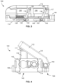
- the first example of an implant 100 comprises a top plate 112, a bottom plate 114, linkages 116 connecting the top and bottom plates 112, 114, a drive shaft 118 (see FIG. 8 ) coupled to the linkages 116 and a threaded coupling 120 between the bottom plate 114 and the drive shaft 118.
- the top plate 112 has an upper bone contacting surface 122 and an opposite interior surface 124 (see FIG. 7 ). As shown in the example, the top plate 112 includes one or more fusion apertures 126 extending through the bone contacting surface 122 and interior surface 124.
- the interior surface 124 includes recesses 128 to accommodate the linkages 116 in the interior of the implant 100.
- the recesses 128 further comprise a pocket 127 that houses the superior ends 117 of the linkages 116. As shown in FIG. 3 , the superior ends 117 of the linkages 116 are coupled to the interior surface 124 of the top plate 112 via a pivot pin 130.
- the bottom plate 114 has a lower bone contacting surface 132 and an opposite interior surface 134.
- the bottom plate 114 includes one or more fusion apertures 126 extending through the lower bone contacting surface 132 and the opposite interior surface 134.
- the distal wall 136 of the lower plate 114 includes a threaded hole for receiving the threaded coupling 120.
- the anterior wall 140 of the bottom plate 114 includes pin slots (not shown) configured to receive pins that couple the inferior end of the linkages 116 to the bottom plate 114.
- the proximal end 141 of the bottom plate 114 includes a recess 142 configured to receive a detachable fixation tab 144.
- the recess 142 has a shape that complements the shape of the attachment portion 146 of the detachable fixation tab 144. As shown in the example, the recess 142 and the attachment portion 146 of the detachable tab 144 are generally flower shaped to allow the tab 144 to be attached in a variety of positions, however, other shapes may be implemented.
- the interior surface 134 of the bottom plate 114 houses the drive shaft 118. As illustrated in the example in Figs. 1-8 , the interior surface 134 of the bottom plate 114 includes a track dimensioned to receive the drive shaft 118. As shown best in FIGS. 3 and 8 , the distal end 138 of the drive shaft 118 includes a hole for receiving the threaded coupling 120. The drive shaft 118 further includes pin holes 148 dimensioned to receive the pin 150 that couples the inferior end 152 of the linkages 116 to the bottom plate 114.
- One end of the pin 150 resides and translates within the slots 156 in the anterior wall 158 of the bottom plate 114, the center of the pin 150 is received in a pin hole through the inferior end 152 of the linkages 116 and a second end of the pin 150 is received in the pin hole 148 in the drive shaft 118.
- the drive shaft 118 is configured such that when the implant 100 is in its collapsed configuration, the distal surface 138 of the drive shaft 118 is in close proximity to the proximal face 160 of the distal wall 136 of the bottom plate 114. As the threaded coupling 120 is rotated in a first direction, the drive shaft 118 translates in a proximal direction. Translation of the drive shaft 118 in the proximal direction causes the pins 150 received through the inferior ends 152 of the linkages 116 to slide proximally within the pin slots 156 in the bottom plate 114 while causing the linkages 116 to pivot about the pivot pin 130 coupled to the top plate 112.
- the pivoting of the linkages 116 about the pivot pin 130 allows the linkages 116 to move from a first, generally horizontal position in the interior of the implant 100 to a second, more vertical position, pushing the top plate 112 upwards and thereby causing a change in the anterior height of the implant 100 when the implant is in its expanded state.
- the top plate 112 is coupled to the bottom plate 114 via a hinge 162 on the posterior side 164 of the implant 100.
- the described expansion mechanism allows the lordotic angle of the implant 100 to be increased in non-discrete increments, meaning the surgeon can increase the angle of lordosis until the desired amount of lordosis is reached.
- the implant 100 can be packed with bone graft or bone graft substitute through the same hole 166 through which instruments used to actuate the drive mechanism are inserted.
- the fixation tab 144 is coupled to the proximal end 141 of the implant 100.
- the fixation tab 144 includes a superior and an inferior extension 168, 169 with a screw hole 167 therethough.
- the superior extension 168 is configured to be positioned adjacent the superior vertebral body and the inferior extension 169 is configured to be positioned adjacent the inferior vertebral body.
- a fixation tab 144 with a single extension for receiving a single screw therethrough and positioned adjacent only one of the superior and inferior vertebral body is also contemplated. It is also contemplated that the extensions include an anti-backout element for preventing backout of the screws after they've been placed through the extension and into the vertebral body. Further details of an exemplary fixation tab 144 are shown in FIGS. 31-33 .
- a method (not claimed) of using the implant 100 is as follows: a disc space is accessed via a lateral approach; the disc space is prepared to receive an intervertebral implant; the implant 100 is inserted into the prepared disc space in its collapsed position having 0 degrees of lordosis; an expansion tool is used to rotate the threaded coupling 120, thereby causing the drive shaft 118 to translate in a proximal direction; the implant 100 is expanded until the desired degree of lordosis is achieved; the expansion tool is withdrawn from the implant 100; bone graft or bone graft substitute is packed into the interior of the implant 100; a fixation tab 144 is attached to the proximal end 140 of the implant 100 and at least one screw is inserted through the fixation tab 144 into the vertebral body.
- FIGS. 9-14 illustrate an alternative embodiment of the expandable lordosis intervertebral implant.
- the implant according to this embodiment shares many of the same features as the implant of FIGS. 1-8 .
- the same features and elements will not be re-described in this embodiment but may be labeled using a "2" instead of a "1" as the first digit of the three digit label.
- the reader should understand that the features are the same or similar as in the first embodiment. Attention will be directed to the distinctions between this embodiment and the embodiment presented in FIGS. 1-8 .
- One of the differences according to this alternative embodiment is that the top plate 212 and the bottom plate 214 include planar extensions 213, 215 that together define an anterior wall when the implant 200 is in its expanded state. These planar extensions 213, 215 are configured to enclose the generally hollow interior of the implant 200.
- the expansion mechanism of the device 200 includes a chassis 270 with a threaded interior.
- the drive screw 390 resides within the chassis 270 and has threads that engage the threaded interior of the chassis 270. Turning the drive screw causes the chassis 270 to translate proximally, consequently causing pins 250 coupled to the chassis 270 to translate proximally within slots 256 in the bottom anterior wall 215 of the bottom plate 214.
- Linkages 216 are coupled to these pins 250 at their inferior end and coupled to the top plate 212, such that when the chassis 270 translates proximally, the inferior ends of the linkages 216 are moved proximally, causing the linkages 216 to move to a more upright position and thereby causing the top plate 212 to move upward and away from the bottom plate 214, increasing the height and lordotic angle of the implant.
- This motion may be viewed in the figures as FIGS. 9 and 10 show the implant 200 in a low profile, closed/collapsed configuration.
- FIG. 10 shows the position of the various components with the top plate 212 removed for a better depiction of the mechanism, with pins 250 in a distal most position within their respective slots 256.
- FIGS. 9 and 10 show the implant 200 in a low profile, closed/collapsed configuration.
- FIG. 10 shows the position of the various components with the top plate 212 removed for a better depiction of the mechanism, with pins 250 in a distal most position within
- FIGS. 13 and 14 show the implant 200 from a lower perspective view ( FIG. 13 ) and a side view ( FIG. 14 ) in an open, expanded position with pins 250 having been translated proximally within slots 256, thereby pushing linkages 216 in a vertical manner, which results in the lifting of the top plate 212.
- FIGS. 9-14 presents alternative additional features not shown in FIGS. 1-8 .
- the top plate 212 has an additional top anterior cover 213 and the bottom plate 214 has an additional bottom anterior cover 215 which together serve to cover the entire anterior portion of the implant 200 when in a collapsed or expanded implant configuration. Further, top anterior cover 213 is lifted along with the top plate 212 when the pins 250 are slid proximally within the pin slots 256.
- Anti-migration features 211 on the exterior portions of both the top plate 212 and the bottom plate 214 serve to provide further frictional and contact surface between the implant 200 and the adjoining vertebrae.
- FIGS. 15-30 illustrate an embodiment of the expandable lordosis intervertebral implant.
- the implant according to this embodiment shares many of the same features as the example of FIGS. 1-8 , and the example of FIGS. 9-14 .
- the same features will not be re-described in this embodiment but may be labeled using a "3" instead of a "1" or "2" as the first digit of the three digit label.
- the reader should understand that the features are the same or similar as in the first and second embodiments. Attention will be directed to the distinctions between this embodiment and the prior described embodiments. Similar to the embodiment shown and described in FIGS.
- the present embodiment also has a top plate 312 and a bottom plate 314 which include planar extensions 313, 315 that together define an anterior wall when the implant 300 is in its expanded state. These extensions 313, 315 are configured to enclose the generally hollow interior of the implant 300.
- An additional feature is a number of projections 317 on both the top plate 312 external surface and bottom plate 314 external surface. These fang-like projections 317 work in conjunction with the anti-migration features 311 on the top plate 312 and bottom plate 314 surfaces to create a friction fit with adjoining vertebrae.
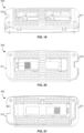
- FIGS. 22-24 show a chassis 380 and its relative positioning within the bottom plate 314.
- a set of primary linkages 381 having spherical end portions 382 are connected to a set of support linkages 383, which are connected to the body portion 385 of the chassis 380 via pins 384.
- the pins 384 serve as the axis of rotation of the support linkages 383, which in turn allow for rotation of the primary linkages 381 via pins 386.
- the primary linkages 381 are not directly connected to the chassis body 385. Thus, the primary linkages 381 only articulate about a rotational axis formed by pins 386, and do not translate.
- the support linkages 383 both articulate and translate.
- Chassis 380 includes oval protrusions 387 which are aligned with channels 319 and used to "drop down" the chassis 380 within the internal frame of the bottom plate 314 and then shift the chassis 380 back distally to lock the chassis 380 within the frame of the bottom plate 314. This mechanism secures the position of the chassis 380 with respect to the bottom plate 314.
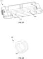
- Screw 390 in conjunction with washer 391 act to lock the expansion/collapsing mechanism within chassis 380. As shown in FIG. 29 , the screw 390 with washer 391 are locked into position by a friction fit within an accommodating portion 393 of the bottom plate 314. Additionally, raptor spring 392 has a protrusion 394 which provides further a locking mechanism for the screw 390 to position it within place. The protrusion 394 mates with divots 395 positioned annularly to form an annular flower pattern. A divot is available every 15-20 degrees such that a ratcheting mechanism is available for the surgeon to determine the precise level of openness of the top plate 312 is desired.
- the protrusion 394 of the spring 392 is allowed to mate with divot 395 of the bottom plate 314, to essentially lock the position and prevent further movement. Some level of force is required to further open or close the top plate 312.
- Top plate 312 is opened up by the mechanism driven by the chassis 380 such that the spherical heads 382 of the primary linkages 381 push the top plate 312 upward by physical upward force. This is essentially the expansion mechanism. Contraction or collapsing of the implant 300 involves a different mechanism which is also positioned on the chassis 380. As shown in FIG. 30 , a diagonally cut groove 396 in the body of the chassis 385 allows for the diagonal translation of a protrusion 397 in the chassis 380, which is connected to the top plate 312 through connection 398. The contracted implant 300 has the protrusion 397 in its lowermost position on a distal end of the groove 396. This serves to maintain a relatively tight connection and parallel configuration between the top plate 312 and the bottom plate 314.
- the protrusion As the expansion mechanism is activated, the protrusion is extended proximally such that it begins to lift up diagonally in the groove 396, thereby lifting the top plate 312. However, if there is desire to contract the implant 300, the protrusion 397 travels back down the groove 396, serving to lower the connection 398 between the top 312 and bottom 314 plates, and therefore the top plate 312 is lowered down toward the bottom plate 314 again.
- this sliding protrusion mechanism is passive, and during the contraction mechanism, this sliding protrusion mechanism becomes active to pull down the top plate 312.
- fixation devices with locking and anti-backout mechanisms may be used with the implants 100, 200, and 300 shown in the present disclosure.
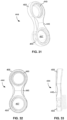
- FIGS. 31-33 One such type is shown in FIGS. 31-33 .
- fixation device 444 with anti-backout device has a top circular portion 468 and bottom circular portion 469 having an aperture 467 therein.
- the middle portion 446 is the engagement mechanism which services to lock into an accommodating portion of an implant, such as those shown in FIGS. 1-2 .
- the device shown contains a canted coil mechanism 449 as its anti-backout mechanism, but other types may also be used to secure the implant position with respect to adjacent vertebra once it is placed and sized.
Landscapes
- Health & Medical Sciences (AREA)
- Engineering & Computer Science (AREA)
- Biomedical Technology (AREA)
- Neurology (AREA)
- Orthopedic Medicine & Surgery (AREA)
- Cardiology (AREA)
- Oral & Maxillofacial Surgery (AREA)
- Transplantation (AREA)
- Heart & Thoracic Surgery (AREA)
- Vascular Medicine (AREA)
- Life Sciences & Earth Sciences (AREA)
- Animal Behavior & Ethology (AREA)
- General Health & Medical Sciences (AREA)
- Public Health (AREA)
- Veterinary Medicine (AREA)
- Prostheses (AREA)
Claims (15)
- Implantatvorrichtung (300), umfassend:- eine obere Platte (312), die mit einer unteren Platte (314) durch ein Scharnier (362) verbunden ist, wobei die obere Platte (312) eine verlängerte Vorderwand (313) und die untere Platte (314) eine verlängerte Vorderwand (315) aufweist;- eine Verbindung (381, 383), die zwischen der oberen (312) und unteren (314) Platte angeordnet ist;- ein bewegliches Chassis (380), das innerhalb der unteren Platte (314) positioniert ist;- eine Schraube (390), die innerhalb des beweglichen Chassis (380) positioniert ist und mit diesem in Eingriff steht; und- eine Unterlegscheibe (391), die um die Schraube (390) angeordnet ist,- wobei die Drehung der Schraube (390) eingerichtet ist, um eine inkrementelle Ratschenbewegung des Chassis (380) zu bewirken, und um zu bewirken, dass sich die Verbindung (381, 383) von einer zusammengeklappten Position, in der die verlängerte Vorderwand (313) der oberen Platte (312) und die verlängerte Vorderwand (315) der unteren Platte (314) im Wesentlichen parallel zueinander sind, in eine erweiterte Position bewegt, in der die obere Platte (312) von der unteren Platte (314) weggedrückt wird, so dass die obere Platte (312) und die untere Platte (314) einen Winkel zueinander bilden.
- Vorrichtung (300) nach Anspruch 1, wobei die Verbindung (381, 383) ferner eine drehbar gelenkige Primärverbindung (381) mit einem kugelförmigen Kopfabschnitt (382) aufweist, der im Chassis (380) angeordnet ist, wobei der kugelförmige Kopfabschnitt (382) mit einer Innenwand (326) der oberen Platte (312) in Verbindung steht.
- Vorrichtung (300) nach Anspruch 2, wobei die Verbindung (381, 383) ferner eine drehbar gelenkige und linear verschiebbare Sekundärverbindung (383) aufweist, die direkt mit dem Chassis (380) verbunden ist und die Drehbewegung der Primärverbindung (381) ausrichtet.
- Vorrichtung (300) nach Anspruch 1, die ferner einen diagonalen Schlitz (396) aufweist, der innerhalb des Chassis (380) positioniert ist, und eingerichtet ist, um einen Vorsprung (397) aufzunehmen, der an der oberen Platte (312) angeordnet ist, und um eine Aufwärtsbewegung der oberen Platte (312) während der Bewegung in die erweiterte Position passiv zu ermöglichen, indem dem Vorsprung (397) ermöglicht wird, sich entlang des diagonalen Schlitzes (396) zu verschieben, wobei der diagonale Schlitz (396) ferner eingerichtet ist, um die obere Platte (312) während einer Bewegung in die zusammengeklappte Position nach unten zu ziehen, indem der Vorsprung (397) innerhalb des Schlitzes (396) nach unten gezogen wird.
- Vorrichtung (300) nach Anspruch 1, wobei das Chassis (380) darauf angeordnete Vorsprünge (387) aufweist, die innerhalb von Aufnahmekanälen (319) in der unteren Platte (314) gleiten und dort verriegelt sind.
- Vorrichtung (300) nach Anspruch 1, wobei jede der oberen (312) und unteren (314) Platten ein Antimigrationsmerkmal (311) und einen Vorsprung (317) aufweist, der eingerichtet ist, um in den Knochen einzugreifen.
- Vorrichtung (300) nach Anspruch 1, wobei die Schraube (390) und die Unterlegscheibe (391) durch eine Reibungspassung innerhalb eines Abschnitts (393) der unteren Platte (314) in ihrer Position verriegelt sind.
- Vorrichtung (300) nach Anspruch 1, die ferner eine Feder (392) aufweist, die an der Schraube (390) zwischen der Unterlegscheibe (391) und dem Chassis (380) positioniert ist.
- Vorrichtung (300) nach Anspruch 8, die ferner einen Vorsprung (394) aufweist, der an der Feder (392) angeordnet ist, und eine oder mehrere Vertiefungen (395) aufweist, die an der Bodenplatte (314) angeordnet sind, wobei der Vorsprung (394) und die eine oder mehrere Vertiefungen (395) zusammenwirken, um die inkrementelle Ratschenbewegung zu erzeugen.
- Vorrichtung (300) nach Anspruch 9, wobei die Vertiefungen (395) ringförmig angeordnet sind, so dass eine Vertiefung (395) alle 15 bis 20 Grad verfügbar ist.
- Vorrichtung (300) nach Anspruch 1, wobei die Schraube (390) ein Außengewinde aufweist, das eingerichtet ist, um in ein Innengewinde des Chassis (380) einzugreifen, so dass eine Drehung der Schraube (390) bewirkt, dass sich das Chassis (380) entlang des Außengewindes der Schraube (390) verschiebt.
- Vorrichtung (300) nach Anspruch 1, wobei die Bodenplatte (314) ein proximales Ende (371) mit einer sich darin erstreckenden Einführöffnung (375) aufweist.
- Vorrichtung (300) nach Anspruch 12, wobei das proximale Ende (371) der Bodenplatte (314) eingerichtet ist, um in eine Fixierungsvorrichtung (444) einzugreifen.
- Vorrichtung (300) nach Anspruch 12, wobei das proximale Ende (371) der Bodenplatte (314) eine oder mehrere sich darin erstreckende Öffnungen (377) aufweist.
- Vorrichtung (300) nach Anspruch 14, wobei der Einführabschnitt (375) und die eine oder mehrere Öffnungen (377) eingerichtet sind, um in ein Einführwerkzeug einzugreifen.
Applications Claiming Priority (3)
| Application Number | Priority Date | Filing Date | Title |
|---|---|---|---|
| US201562160544P | 2015-05-12 | 2015-05-12 | |
| US201562190251P | 2015-07-09 | 2015-07-09 | |
| PCT/US2016/032216 WO2016183382A1 (en) | 2015-05-12 | 2016-05-12 | Expandable lordosis intervertebral implants |
Publications (2)
| Publication Number | Publication Date |
|---|---|
| EP3294223A1 EP3294223A1 (de) | 2018-03-21 |
| EP3294223B1 true EP3294223B1 (de) | 2024-10-16 |
Family
ID=56027247
Family Applications (1)
| Application Number | Title | Priority Date | Filing Date |
|---|---|---|---|
| EP16724244.5A Active EP3294223B1 (de) | 2015-05-12 | 2016-05-12 | Expandierbare lordose-bandscheibenimplantate |
Country Status (5)
| Country | Link |
|---|---|
| US (2) | US11234833B2 (de) |
| EP (1) | EP3294223B1 (de) |
| JP (2) | JP6949725B2 (de) |
| AU (2) | AU2016260301B2 (de) |
| WO (1) | WO2016183382A1 (de) |
Families Citing this family (55)
| Publication number | Priority date | Publication date | Assignee | Title |
|---|---|---|---|---|
| US10842642B2 (en) * | 2009-04-16 | 2020-11-24 | Nuvasive, Inc. | Methods and apparatus of performing spine surgery |
| US12193948B2 (en) | 2013-03-13 | 2025-01-14 | Life Spine, Inc. | Expandable implant assembly |
| US10426632B2 (en) | 2013-03-13 | 2019-10-01 | Life Spine, Inc. | Expandable spinal interbody assembly |
| US10500061B2 (en) * | 2015-08-13 | 2019-12-10 | K2M, Inc. | Adjustable spinal implant |
| US10940018B2 (en) | 2016-05-20 | 2021-03-09 | Howmedica Osteonics Corp. | Expandable interbody implant with lordosis correction |
| EP3487448B1 (de) | 2016-07-21 | 2024-08-28 | Seaspine, Inc. | Expandierbares implantat |
| WO2018049227A1 (en) | 2016-09-08 | 2018-03-15 | Mayo Foundation For Medical Education And Research | Spinal fixation system |
| AU2017228529B2 (en) | 2016-09-12 | 2022-03-10 | Vb Spine Us Opco Llc | Interbody implant with independent control of expansion at multiple locations |
| AU2017251734B2 (en) | 2016-10-26 | 2022-10-20 | Vb Spine Us Opco Llc | Expandable interbody implant with lateral articulation |
| US9962272B1 (en) | 2017-06-28 | 2018-05-08 | Amendia, Inc. | Intervertebral implant device with lordotic expansion |
| US11896494B2 (en) | 2017-07-10 | 2024-02-13 | Life Spine, Inc. | Expandable implant assembly |
| JP7337087B2 (ja) * | 2017-12-18 | 2023-09-01 | ニューヴェイジヴ,インコーポレイテッド | 拡張可能なインプラントデバイス |
| EP3755273B1 (de) * | 2018-02-22 | 2025-04-30 | Warsaw Orthopedic, Inc. | Expandierbares wirbelsäulenimplantatsystem |
| US11806250B2 (en) | 2018-02-22 | 2023-11-07 | Warsaw Orthopedic, Inc. | Expandable spinal implant system and method of using same |
| US11013616B2 (en) * | 2018-10-10 | 2021-05-25 | K2M, Inc. | Sagittal balance systems and methods of use thereof |
| KR102163985B1 (ko) * | 2018-12-12 | 2020-10-12 | 주식회사 메디너스 | 척추체간 확장형 케이지 |
| WO2020251943A1 (en) | 2019-06-10 | 2020-12-17 | Life Spine, Inc. | Expandable implant assembly with compression features |
| US12042395B2 (en) | 2019-06-11 | 2024-07-23 | Life Spine, Inc. | Expandable implant assembly |
| US11857432B2 (en) | 2020-04-13 | 2024-01-02 | Life Spine, Inc. | Expandable implant assembly |
| US11602439B2 (en) * | 2020-04-16 | 2023-03-14 | Life Spine, Inc. | Expandable implant assembly |
| US12336917B2 (en) | 2020-05-15 | 2025-06-24 | Life Spine, Inc. | Steerable implant assembly |
| US11602440B2 (en) | 2020-06-25 | 2023-03-14 | Life Spine, Inc. | Expandable implant assembly |
| US11554020B2 (en) | 2020-09-08 | 2023-01-17 | Life Spine, Inc. | Expandable implant with pivoting control assembly |
| US11376134B1 (en) | 2020-11-05 | 2022-07-05 | Warsaw Orthopedic, Inc. | Dual expanding spinal implant, system, and method of use |
| US12121453B2 (en) | 2020-11-05 | 2024-10-22 | Warsaw Orthopedic, Inc. | Dual wedge expandable implant with eyelets, system, and method of use |
| US11395743B1 (en) | 2021-05-04 | 2022-07-26 | Warsaw Orthopedic, Inc. | Externally driven expandable interbody and related methods |
| US11291554B1 (en) | 2021-05-03 | 2022-04-05 | Medtronic, Inc. | Unibody dual expanding interbody implant |
| US12318308B2 (en) | 2020-11-05 | 2025-06-03 | Warsaw Orthopedic, Inc. | Dual expandable inter-body device |
| US12239544B2 (en) | 2020-11-05 | 2025-03-04 | Warsaw Orthopedic, Inc. | Rhomboid shaped implants |
| US11517443B2 (en) | 2020-11-05 | 2022-12-06 | Warsaw Orthopedic, Inc. | Dual wedge expandable implant, system and method of use |
| US11833059B2 (en) | 2020-11-05 | 2023-12-05 | Warsaw Orthopedic, Inc. | Expandable inter-body device, expandable plate system, and associated methods |
| US11638653B2 (en) | 2020-11-05 | 2023-05-02 | Warsaw Orthopedic, Inc. | Surgery instruments with a movable handle |
| US11285014B1 (en) | 2020-11-05 | 2022-03-29 | Warsaw Orthopedic, Inc. | Expandable inter-body device, system, and method |
| US12171439B2 (en) | 2020-11-05 | 2024-12-24 | Warsaw Orthopedic, Inc. | Protected drill |
| US11564724B2 (en) | 2020-11-05 | 2023-01-31 | Warsaw Orthopedic, Inc. | Expandable inter-body device, system and method |
| US11963881B2 (en) | 2020-11-05 | 2024-04-23 | Warsaw Orthopedic, Inc. | Expandable inter-body device, system, and method |
| US11701240B2 (en) * | 2021-02-19 | 2023-07-18 | Loubert S. Suddaby | Expandable intervertebral fusion implant |
| EP4312890B1 (de) | 2021-04-02 | 2025-11-05 | Nuvasive, Inc. | Erweiterungstreiber |
| WO2022216564A1 (en) | 2021-04-04 | 2022-10-13 | Nuvasive, Inc. | Expandable spinal fusion implants and insertion devices |
| US12427036B2 (en) | 2021-04-04 | 2025-09-30 | Nuvasive, Inc. | Expandable implants |
| US12295865B2 (en) | 2021-06-24 | 2025-05-13 | Warsaw Orthopedic, Inc. | Expandable interbody implant and corresponding inserter |
| US12485019B2 (en) | 2021-06-24 | 2025-12-02 | Warsaw Orthopedic, Inc. | Parallel jaw inserter |
| US12268614B2 (en) | 2021-06-24 | 2025-04-08 | Warsaw Orthopedic, Inc. | Interbody implant with adjusting shims |
| US12440349B2 (en) | 2021-11-01 | 2025-10-14 | Warsaw Orthopedic, Inc. | Expandable interbody implant and breakoff screw |
| US11612499B2 (en) | 2021-06-24 | 2023-03-28 | Warsaw Orthopedic, Inc. | Expandable interbody implant |
| WO2022271280A1 (en) * | 2021-06-24 | 2022-12-29 | Warsaw Orthopedic, Inc. | Expandable interbody implant and corresponding surgical tool |
| US11730608B2 (en) | 2021-07-13 | 2023-08-22 | Warsaw Orthopedic, Inc. | Monoblock expandable interbody implant |
| WO2023285675A1 (en) | 2021-07-16 | 2023-01-19 | Blue Ocean Spine Gmbh | Adjustable intervertebral cage, associated instrument and manufacturing process therefor |
| US12453640B2 (en) | 2021-07-16 | 2025-10-28 | Blue Ocean Spine Gmbh | Adjustable spinal implants, associated instruments and methods |
| US11850163B2 (en) | 2022-02-01 | 2023-12-26 | Warsaw Orthopedic, Inc. | Interbody implant with adjusting shims |
| US12076252B2 (en) * | 2022-06-30 | 2024-09-03 | Ingeniumspine, LLC | Lordotic intervertebral spacer with ratchet locking mechanism and integral expansion mechanism |
| US12011370B2 (en) * | 2022-06-30 | 2024-06-18 | Ingeniumspine, LLC | Expandable vertebral spacer with four locking mechanisms |
| US12533242B2 (en) | 2023-01-18 | 2026-01-27 | Blue Ocean Spine Gmbh | Adjustable spinal implants and related deployment instruments |
| CN116196155B (zh) * | 2023-02-23 | 2024-01-26 | 重庆富沃思医疗器械有限公司 | 一种腰椎椎间融合器 |
| US12533241B2 (en) | 2023-05-16 | 2026-01-27 | Warsaw Orthopedic, Inc. | Distracting and angling expandable interbody device |
Citations (1)
| Publication number | Priority date | Publication date | Assignee | Title |
|---|---|---|---|---|
| WO2016073214A1 (en) * | 2014-11-04 | 2016-05-12 | Warsaw Orthopedic, Inc. | Expandable interbody implant |
Family Cites Families (149)
| Publication number | Priority date | Publication date | Assignee | Title |
|---|---|---|---|---|
| US5171278A (en) | 1991-02-22 | 1992-12-15 | Madhavan Pisharodi | Middle expandable intervertebral disk implants |
| US5390683A (en) | 1991-02-22 | 1995-02-21 | Pisharodi; Madhavan | Spinal implantation methods utilizing a middle expandable implant |
| JP3390431B2 (ja) | 1991-02-22 | 2003-03-24 | マドハヴァン、ピシャロディ | 中央部拡張可能な椎間板移植片および方法 |
| RU2070006C1 (ru) | 1993-03-29 | 1996-12-10 | Российский научно-исследовательский нейрохирургический институт им.проф.А.Л.Поленова | Межпозвонковый дистрактор |
| FR2717068B1 (fr) | 1994-03-14 | 1996-04-26 | Biomat | Cage intersomatique vertébrale. |
| AU2212695A (en) | 1994-03-23 | 1995-10-09 | Schnorrenberg Chirurgiemechanik Gmbh | Positioning and support device for the spinal column |
| US5782832A (en) | 1996-10-01 | 1998-07-21 | Surgical Dynamics, Inc. | Spinal fusion implant and method of insertion thereof |
| US20070282443A1 (en) | 1997-03-07 | 2007-12-06 | Disc-O-Tech Medical Technologies Ltd. | Expandable element |
| US6126689A (en) | 1998-06-15 | 2000-10-03 | Expanding Concepts, L.L.C. | Collapsible and expandable interbody fusion device |
| US6183517B1 (en) | 1998-12-16 | 2001-02-06 | Loubert Suddaby | Expandable intervertebral fusion implant and applicator |
| US6582451B1 (en) | 1999-03-16 | 2003-06-24 | The University Of Sydney | Device for use in surgery |
| AU2007202404A1 (en) | 1999-05-07 | 2007-06-14 | Warsaw Orthopedic, Inc. | Instrumentation with inwardly movable extensions for inserting an expandable interbody spinal fusion implant |
| US6419702B1 (en) | 1999-08-13 | 2002-07-16 | Bret A. Ferree | Treating degenerative disc disease through transplantation of the nucleus pulposis |
| US6340369B1 (en) | 1999-08-13 | 2002-01-22 | Bret A. Ferree | Treating degenerative disc disease with harvested disc cells and analogues of the extracellular matrix |
| US6491724B1 (en) | 1999-08-13 | 2002-12-10 | Bret Ferree | Spinal fusion cage with lordosis correction |
| WO2001001895A1 (en) | 1999-07-02 | 2001-01-11 | Petrus Besselink | Reinforced expandable cage |
| US6344058B1 (en) | 1999-08-13 | 2002-02-05 | Bret A. Ferree | Treating degenerative disc disease through transplantation of allograft disc and vertebral endplates |
| US6719797B1 (en) | 1999-08-13 | 2004-04-13 | Bret A. Ferree | Nucleus augmentation with in situ formed hydrogels |
| US6352557B1 (en) | 1999-08-13 | 2002-03-05 | Bret A. Ferree | Treating degenerative disc disease through transplantion of extracellular nucleus pulposus matrix and autograft nucleus pulposus cells |
| US6648918B2 (en) | 1999-08-13 | 2003-11-18 | Bret A. Ferree | Treating degenerative disc disease through the transplantation of dehydrated tissue |
| US6814756B1 (en) | 2000-02-04 | 2004-11-09 | Gary K. Michelson | Expandable threaded arcuate interbody spinal fusion implant with lordotic configuration during insertion |
| US6709458B2 (en) | 2000-02-04 | 2004-03-23 | Gary Karlin Michelson | Expandable push-in arcuate interbody spinal fusion implant with tapered configuration during insertion |
| US6500205B1 (en) | 2000-04-19 | 2002-12-31 | Gary K. Michelson | Expandable threaded arcuate interbody spinal fusion implant with cylindrical configuration during insertion |
| US6716247B2 (en) | 2000-02-04 | 2004-04-06 | Gary K. Michelson | Expandable push-in interbody spinal fusion implant |
| EP1645248B8 (de) | 2000-02-04 | 2010-06-16 | Warsaw Orthopedic, Inc. | Ausdehnbares interspinales Fusionsimplantat mit schwenkbarem Blocker |
| US6332895B1 (en) | 2000-03-08 | 2001-12-25 | Loubert Suddaby | Expandable intervertebral fusion implant having improved stability |
| US6808537B2 (en) | 2000-07-07 | 2004-10-26 | Gary Karlin Michelson | Expandable implant with interlocking walls |
| FR2813519B1 (fr) | 2000-09-07 | 2003-07-18 | Eurosurgical | Implant intersomatique souple |
| US6986772B2 (en) | 2001-03-01 | 2006-01-17 | Michelson Gary K | Dynamic lordotic guard with movable extensions for creating an implantation space posteriorly in the lumbar spine |
| DE60201945T2 (de) | 2001-02-04 | 2005-12-01 | Michelson, Gary Karlin, Los Angeles | Instrument zum Einführen und Spreiten eines Zwischenwirbelfusionsimplantats |
| US6576017B2 (en) * | 2001-02-06 | 2003-06-10 | Sdgi Holdings, Inc. | Spinal implant with attached ligament and methods |
| US6368351B1 (en) | 2001-03-27 | 2002-04-09 | Bradley J. Glenn | Intervertebral space implant for use in spinal fusion procedures |
| FR2822674B1 (fr) * | 2001-04-03 | 2003-06-27 | Scient X | Systeme stabilise de fusion intersomatique pour vertebres |
| KR100395252B1 (ko) | 2001-04-30 | 2003-08-21 | (주)태연메디칼 | 척추 융합 이식물 |
| NL1018438C1 (nl) | 2001-07-02 | 2003-01-08 | Baat Medical Engineering B V | In- en uitklapbaar gereedschap voor plaatsing in een ruggenwervel. |
| DE10138079B4 (de) | 2001-08-03 | 2004-02-12 | Biedermann Motech Gmbh | Platzhalter mit veränderbarer axialer Länge |
| US20040236342A1 (en) | 2002-04-23 | 2004-11-25 | Ferree Bret A. | Device to assess ADR motion |
| US8317798B2 (en) | 2002-06-25 | 2012-11-27 | Warsaw Orthopedic | Minimally invasive expanding spacer and method |
| US7087055B2 (en) | 2002-06-25 | 2006-08-08 | Sdgi Holdings, Inc. | Minimally invasive expanding spacer and method |
| US7070598B2 (en) | 2002-06-25 | 2006-07-04 | Sdgi Holdings, Inc. | Minimally invasive expanding spacer and method |
| US7044971B2 (en) | 2002-08-30 | 2006-05-16 | Loubert Suddaby | Lordotic fusion implant |
| IL155146A0 (en) | 2003-03-30 | 2003-10-31 | Expandis Ltd | Minimally invasive distraction device and method |
| DE10344019B3 (de) | 2003-09-16 | 2005-05-25 | Aesculap Ag & Co. Kg | Wirbelsäulenimplantat |
| US20050080422A1 (en) | 2003-10-14 | 2005-04-14 | Centerpulse Spine-Tech, Inc. | Instruments for use with implants, and methods |
| US7763028B2 (en) | 2004-02-13 | 2010-07-27 | Warsaw Orthopedic, Inc. | Spacer with height and angle adjustments for spacing vertebral members |
| US20050256576A1 (en) | 2004-05-13 | 2005-11-17 | Moskowitz Nathan C | Artificial expansile total lumbar and thoracic discs for posterior placement without supplemental instrumentation and its adaptation for anterior placement of artificial cervical, thoracic and lumbar discs |
| US8251891B2 (en) | 2004-05-14 | 2012-08-28 | Nathan Moskowitz | Totally wireless electronically embedded action-ended endoscope utilizing differential directional illumination with digitally controlled mirrors and/or prisms |
| FR2871366A1 (fr) | 2004-06-09 | 2005-12-16 | Ceravic Soc Par Actions Simpli | Implant expansible prothetique osseux |
| AU2011203582B2 (en) | 2004-06-09 | 2013-07-04 | Stryker European Operations Limited | Methods and Apparatuses for Bone Restoration |
| US20050278023A1 (en) | 2004-06-10 | 2005-12-15 | Zwirkoski Paul A | Method and apparatus for filling a cavity |
| US7678148B2 (en) | 2004-07-23 | 2010-03-16 | Warsaw Orthopedic, Inc. | Expandable spinal implant having interlocking geometry for structural support |
| WO2006042334A2 (en) | 2004-10-12 | 2006-04-20 | Stout Medical Group, L.P. | Expandable support device and method of use |
| US8409282B2 (en) | 2004-10-20 | 2013-04-02 | Vertiflex, Inc. | Systems and methods for posterior dynamic stabilization of the spine |
| US8128662B2 (en) | 2004-10-20 | 2012-03-06 | Vertiflex, Inc. | Minimally invasive tooling for delivery of interspinous spacer |
| US8152837B2 (en) | 2004-10-20 | 2012-04-10 | The Board Of Trustees Of The Leland Stanford Junior University | Systems and methods for posterior dynamic stabilization of the spine |
| US7763074B2 (en) | 2004-10-20 | 2010-07-27 | The Board Of Trustees Of The Leland Stanford Junior University | Systems and methods for posterior dynamic stabilization of the spine |
| US7615052B2 (en) | 2005-04-29 | 2009-11-10 | Warsaw Orthopedic, Inc. | Surgical instrument and method |
| US20070093822A1 (en) | 2005-09-28 | 2007-04-26 | Christof Dutoit | Apparatus and methods for vertebral augmentation using linked expandable bodies |
| WO2007062080A2 (en) | 2005-11-21 | 2007-05-31 | Philipp Lang | Intervetebral devices and methods |
| EP1968418B1 (de) | 2005-12-09 | 2015-04-15 | Spinal Ventures, Inc. | Reparatur von nichtweichteilen |
| US7901409B2 (en) | 2006-01-20 | 2011-03-08 | Canaveral Villegas Living Trust | Intramedullar devices and methods to reduce and/or fix damaged bone |
| JP2008054710A (ja) | 2006-08-29 | 2008-03-13 | Taeyeon Medical Co Ltd | 脊椎融合手術用移植具 |
| US20100217335A1 (en) | 2008-12-31 | 2010-08-26 | Chirico Paul E | Self-expanding bone stabilization devices |
| US8025697B2 (en) | 2006-09-21 | 2011-09-27 | Custom Spine, Inc. | Articulating interbody spacer, vertebral body replacement |
| GB0620400D0 (en) | 2006-10-13 | 2006-11-22 | Seddon Peter | Spinal implant |
| US8845726B2 (en) | 2006-10-18 | 2014-09-30 | Vertiflex, Inc. | Dilator |
| US20080114367A1 (en) | 2006-11-10 | 2008-05-15 | Syberspine Limited | Method and relaxable distracters for in-situ formation of intervertebral disc prosthesis |
| US8795374B2 (en) | 2007-04-01 | 2014-08-05 | Spinal Kinetics Inc. | Prosthetic intervertebral discs that are implantable by minimally invasive surgical techniques and that have cores that are insertable in situ using end plate guideways |
| US8328818B1 (en) | 2007-08-31 | 2012-12-11 | Globus Medical, Inc. | Devices and methods for treating bone |
| US20090157084A1 (en) | 2007-09-19 | 2009-06-18 | Arthur Martinus Michael Aalsma | Collapsible and expandable device and methods of using same |
| GB2452923A (en) | 2007-09-19 | 2009-03-25 | Surgicraft Ltd | Expandable medical device |
| US8268001B2 (en) | 2007-10-29 | 2012-09-18 | Life Spine, Inc. | Foldable orthopedic implant |
| US8182538B2 (en) | 2007-10-31 | 2012-05-22 | Depuy Spine, Inc. | Expandable fusion cage |
| AU2009205896A1 (en) | 2008-01-17 | 2009-07-23 | Synthes Gmbh | An expandable intervertebral implant and associated method of manufacturing the same |
| US8795365B2 (en) | 2008-03-24 | 2014-08-05 | Warsaw Orthopedic, Inc | Expandable devices for emplacement in body parts and methods associated therewith |
| WO2009125242A1 (en) | 2008-04-08 | 2009-10-15 | Vexim | Apparatus for restoration of the spine and methods of use thereof |
| US20090299478A1 (en) * | 2008-06-03 | 2009-12-03 | Warsaw Orthopedic, Inc. | Lordotic Implant for Posterior Approach |
| EP2299941A1 (de) | 2008-07-18 | 2011-03-30 | Spinalmotion Inc. | Bandscheibenprothese für die hintere wirbelsäule |
| WO2010059860A1 (en) | 2008-11-19 | 2010-05-27 | Endoorthopaedics, Inc. | Intramedullary repair system for bone fractures |
| CN102281829A (zh) | 2008-11-19 | 2011-12-14 | 安杜奥斯皮迪克公司 | 用于骨折的髓内修复系统 |
| WO2010078468A2 (en) | 2008-12-31 | 2010-07-08 | Jimenez Omar F | Methods and apparatus for vertebral body distraction and fusion employing flexure members |
| JP2012514703A (ja) | 2008-12-31 | 2012-06-28 | エフ. ヒメネス、オマール | フレキシャ部材を組み入れた可撓性ジョイント構成 |
| CN101502436B (zh) | 2009-03-11 | 2012-01-25 | 吴乃庆 | 骨扩张融合器 |
| AU2009341783B2 (en) | 2009-03-12 | 2014-11-13 | Stryker European Operations Limited | Apparatus for bone restoration of the spine and methods of use |
| US8628577B1 (en) | 2009-03-19 | 2014-01-14 | Ex Technology, Llc | Stable device for intervertebral distraction and fusion |
| US20110029086A1 (en) | 2009-07-29 | 2011-02-03 | Glazer Paul A | Lumbar jack implant |
| US20140163682A1 (en) | 2012-12-11 | 2014-06-12 | Expandable Vertebral Implant | Expandable Vertebral Implant |
| US20110257748A1 (en) | 2010-04-15 | 2011-10-20 | Jung-Tung Liu | Artificial spinal implant |
| US8690917B2 (en) | 2010-05-12 | 2014-04-08 | Globus Medical, Inc. | Distraction screw |
| WO2011150350A1 (en) | 2010-05-28 | 2011-12-01 | Benvenue Medical, Inc. | Disc space sizing devices and methods of using the same |
| US9220535B2 (en) | 2010-10-26 | 2015-12-29 | Christian Röbling | Process for introducing a stabilizing element into a vertebral column |
| IT1403237B1 (it) | 2010-12-29 | 2013-10-17 | Mikai S P A | Dispositivo percutaneo per il trattamento delle fratture vertebrali |
| JP6223958B2 (ja) | 2011-03-30 | 2017-11-01 | トリニティ・オーソペディックス・リミテッド・ライアビリティ・カンパニーTrinity Orthopedics Llc | 椎間装置 |
| EP2693967B1 (de) | 2011-04-07 | 2017-10-18 | Vexim Sas | Expandierbare orthopädische vorrichtung |
| US8685095B2 (en) | 2011-04-19 | 2014-04-01 | Warsaw Orthopedic, Inc. | Expandable implant system and methods of use |
| US10307254B2 (en) | 2011-07-05 | 2019-06-04 | Corelink, Llc | Bone structural device |
| WO2013052807A2 (en) | 2011-10-05 | 2013-04-11 | H. Lee Moffitt Cancer Center And Research Institute, Inc. | Bone fusion system |
| US20130103154A1 (en) | 2011-10-24 | 2013-04-25 | Warsaw Orthopedic, Inc | Expandable spinal implant and methods of use |
| US9913732B2 (en) | 2011-11-02 | 2018-03-13 | Spinesmith Partners, L.P. | Interbody fusion device with separable retention component for lateral approach and associated methods |
| US20130116791A1 (en) | 2011-11-04 | 2013-05-09 | Boo Holdings, Llc | Expandable intervertebral spacer implant |
| US9445919B2 (en) * | 2011-12-19 | 2016-09-20 | Warsaw Orthopedic, Inc. | Expandable interbody implant and methods of use |
| US20130190876A1 (en) | 2012-01-19 | 2013-07-25 | Warsaw Orthopedic, Inc. | Expandable interbody implant and methods of use |
| US8663329B2 (en) | 2012-01-28 | 2014-03-04 | Mark J Ernst | Expandable implant for mammalian bony segment stabilization |
| CN202568534U (zh) | 2012-04-05 | 2012-12-05 | 田纪伟 | 可调式腰椎间融合器 |
| US9204973B2 (en) | 2012-05-11 | 2015-12-08 | Kamran Aflatoon | Laterally expandable interbody fusion cage |
| US20140039625A1 (en) | 2012-07-31 | 2014-02-06 | Ouroboros Medical, Inc | A minimally-invasive, laterovertically expanding, intervertebral disc scaffolding |
| US10154914B2 (en) | 2012-08-08 | 2018-12-18 | Spectrum Spine Ip Holdings, Llc | Expandable intervertebral cage assemblies |
| US20160022434A1 (en) | 2012-08-08 | 2016-01-28 | James C. Robinson | Expandable intervertebral cage assemblies |
| WO2014025901A2 (en) | 2012-08-08 | 2014-02-13 | Robinson James C | Expandable intervertebral cage assemblies and methods |
| US9839527B2 (en) | 2012-10-24 | 2017-12-12 | Spectrum Spine Ip Holdings, Llc | Expandable inter-body fusion devices and methods |
| US9351851B2 (en) | 2012-11-09 | 2016-05-31 | Bevenue Medical, Inc. | Disc space sizing devices and methods for using the same |
| DE102012023042B3 (de) | 2012-11-26 | 2013-11-28 | Spontech Spine Intelligence Group Ag | Expandierbarer Cage zur interkorporellen Fusion von Lendenwirbeln |
| US10299934B2 (en) | 2012-12-11 | 2019-05-28 | Globus Medical, Inc | Expandable vertebral implant |
| US10350081B2 (en) | 2012-12-11 | 2019-07-16 | Globus Medical, Inc. | Expandable vertebral implant |
| EP2742914A1 (de) | 2012-12-14 | 2014-06-18 | FACET-LINK Inc. | Stufenlos höhenverstellbares Zwischenwirbelfusionsimplantat |
| US9492288B2 (en) | 2013-02-20 | 2016-11-15 | Flexuspine, Inc. | Expandable fusion device for positioning between adjacent vertebral bodies |
| CN203183090U (zh) | 2013-02-20 | 2013-09-11 | 魏志轩 | 微创手术的可扩张式植入物 |
| US10137004B2 (en) | 2013-02-27 | 2018-11-27 | Vivonics, Inc. | Insertion tools and methods for minimally invasive spinal fusion cage |
| US9913728B2 (en) | 2013-03-14 | 2018-03-13 | Quandary Medical, Llc | Spinal implants and implantation system |
| US8828085B1 (en) | 2013-03-15 | 2014-09-09 | Wade K. Jensen | Hinged spinal insert device |
| US9463099B2 (en) | 2013-03-15 | 2016-10-11 | Expanding Orthopedics Inc. | Orthopedic expandable devices |
| EP2967904B1 (de) | 2013-03-15 | 2019-05-08 | Paradigm Spine, LLC. | Modulares, anpassbares wirbelsäulenstabilisierungssystem |
| US9421111B2 (en) | 2013-03-15 | 2016-08-23 | Atlas Spine, Inc. | PLIF hinged spacer |
| US10039650B2 (en) | 2013-03-15 | 2018-08-07 | In Queue Innovations, Llc | Expandable fusion cage system |
| US9119726B2 (en) | 2013-03-18 | 2015-09-01 | Chih-Hsuan Wei | Expandable implant of a minimally invasive surgery |
| US20140296984A1 (en) | 2013-04-01 | 2014-10-02 | Mohammad Etminan | Cage system |
| EP2996592B1 (de) | 2013-05-13 | 2021-07-07 | BioSpine, LLC | Einstellbare vorrichtungen zur intervertebralen fusion |
| US9333093B2 (en) | 2013-05-13 | 2016-05-10 | Kamran Aflatoon | Minimally invasive expandable interbody fusion cage |
| CN105491972A (zh) | 2013-05-14 | 2016-04-13 | 脊柱诊察公司 | 椎间装置和相关方法 |
| WO2014189890A1 (en) | 2013-05-20 | 2014-11-27 | K2M, Inc. | Adjustable implant and insertion tool |
| FR3006169B1 (fr) | 2013-06-03 | 2015-07-03 | Hassan Razian | Cale osseuse |
| US9408721B2 (en) | 2013-07-03 | 2016-08-09 | Spine Innovation, Llc | Methods and apparatus for an insertion guide device |
| US10265192B2 (en) | 2013-07-03 | 2019-04-23 | Spine Innovation, Llc | Methods and apparatus for implanting an interbody device |
| US10149770B2 (en) | 2013-07-09 | 2018-12-11 | Seaspine, Inc. | Orthopedic implant with adjustable angle between tissue contact surfaces |
| US9483829B2 (en) * | 2013-09-04 | 2016-11-01 | International Business Machines Corporation | Efficient visual surface finding |
| WO2015063719A1 (en) | 2013-10-31 | 2015-05-07 | Nlt Spine Ltd. | Adjustable orthopedic implants with releasable retention mechanisms |
| US9820865B2 (en) | 2013-10-31 | 2017-11-21 | Nlt Spine Ltd. | Adjustable implant |
| JP2014073405A (ja) | 2013-12-20 | 2014-04-24 | Vexim Sa | 脊椎の骨修復のための装置および使用方法 |
| FR3015221B1 (fr) | 2013-12-23 | 2017-09-01 | Vexim | Systeme d'implant intravertebral expansible avec fixation pediculaire posterieure |
| US8940049B1 (en) * | 2014-04-01 | 2015-01-27 | Ex Technology, Llc | Expandable intervertebral cage |
| US9585650B2 (en) | 2014-05-29 | 2017-03-07 | Warsaw Orthopedic, Inc. | Surgical spacer instrument and method |
| WO2015198335A1 (en) | 2014-06-25 | 2015-12-30 | Nlt Spine Ltd. | Expanding implant with hinged arms |
| US10405990B2 (en) | 2014-09-09 | 2019-09-10 | Warsaw Orthopedic, Inc. | Spinal implant system and method |
| US20160074174A1 (en) | 2014-09-12 | 2016-03-17 | Nexus Spine, LLC | IBD Expandable Ti |
| CN104248465B (zh) | 2014-09-29 | 2016-11-16 | 中南大学湘雅三医院 | 椎体压缩性骨折撑开植骨装置 |
| CN204306881U (zh) | 2014-12-01 | 2015-05-06 | 薛文 | 一种记忆合金椎间融合器 |
| JP2016013460A (ja) | 2015-09-07 | 2016-01-28 | ヴェクシム エセアー | 脊椎の骨修復のための装置および使用方法 |
| CN204931904U (zh) | 2015-09-22 | 2016-01-06 | 浙江科惠医疗器械股份有限公司 | 一种多关节可转动的大体积融合器 |
| CN105232191A (zh) | 2015-11-06 | 2016-01-13 | 天津市天津医院 | 横向可撑开椎间融合装置 |
-
2016
- 2016-05-12 EP EP16724244.5A patent/EP3294223B1/de active Active
- 2016-05-12 JP JP2017559030A patent/JP6949725B2/ja active Active
- 2016-05-12 US US15/738,098 patent/US11234833B2/en active Active
- 2016-05-12 AU AU2016260301A patent/AU2016260301B2/en active Active
- 2016-05-12 WO PCT/US2016/032216 patent/WO2016183382A1/en not_active Ceased
-
2020
- 2020-09-25 AU AU2020239786A patent/AU2020239786B2/en active Active
-
2021
- 2021-09-22 JP JP2021153966A patent/JP2022008488A/ja active Pending
- 2021-12-17 US US17/644,833 patent/US11938040B2/en active Active
Patent Citations (1)
| Publication number | Priority date | Publication date | Assignee | Title |
|---|---|---|---|---|
| WO2016073214A1 (en) * | 2014-11-04 | 2016-05-12 | Warsaw Orthopedic, Inc. | Expandable interbody implant |
Also Published As
| Publication number | Publication date |
|---|---|
| EP3294223A1 (de) | 2018-03-21 |
| AU2016260301B2 (en) | 2020-06-25 |
| US20220110761A1 (en) | 2022-04-14 |
| US11938040B2 (en) | 2024-03-26 |
| AU2016260301A1 (en) | 2017-11-30 |
| US11234833B2 (en) | 2022-02-01 |
| AU2020239786B2 (en) | 2022-03-03 |
| US20180303621A1 (en) | 2018-10-25 |
| JP2022008488A (ja) | 2022-01-13 |
| AU2020239786A1 (en) | 2020-10-22 |
| WO2016183382A1 (en) | 2016-11-17 |
| JP6949725B2 (ja) | 2021-10-13 |
| JP2018517465A (ja) | 2018-07-05 |
Similar Documents
| Publication | Publication Date | Title |
|---|---|---|
| US11938040B2 (en) | Expandable lordosis intervertebral implants | |
| US12279971B2 (en) | Angling inserter tool for expandable vertebral implant | |
| US11564803B2 (en) | Expandable vertebral implant | |
| AU2018388574B2 (en) | Expandable implant device | |
| US10130489B2 (en) | Expandable vertebral implant | |
| US10369000B2 (en) | Expandable vertebral implant | |
| JP2017221652A (ja) | 拡張可能な椎骨インプラント | |
| US11426287B2 (en) | Expandable vertebral implant | |
| US12589003B2 (en) | Spinal interbody spacer | |
| US20240299187A1 (en) | Expandable interbody devices and instruments | |
| US12403014B2 (en) | Variable lordosis endplate | |
| US12115081B1 (en) | Spinal interbody implant with controlled expansion |
Legal Events
| Date | Code | Title | Description |
|---|---|---|---|
| STAA | Information on the status of an ep patent application or granted ep patent |
Free format text: STATUS: THE INTERNATIONAL PUBLICATION HAS BEEN MADE |
|
| PUAI | Public reference made under article 153(3) epc to a published international application that has entered the european phase |
Free format text: ORIGINAL CODE: 0009012 |
|
| STAA | Information on the status of an ep patent application or granted ep patent |
Free format text: STATUS: REQUEST FOR EXAMINATION WAS MADE |
|
| 17P | Request for examination filed |
Effective date: 20171108 |
|
| AK | Designated contracting states |
Kind code of ref document: A1 Designated state(s): AL AT BE BG CH CY CZ DE DK EE ES FI FR GB GR HR HU IE IS IT LI LT LU LV MC MK MT NL NO PL PT RO RS SE SI SK SM TR |
|
| AX | Request for extension of the european patent |
Extension state: BA ME |
|
| DAV | Request for validation of the european patent (deleted) | ||
| DAX | Request for extension of the european patent (deleted) | ||
| STAA | Information on the status of an ep patent application or granted ep patent |
Free format text: STATUS: EXAMINATION IS IN PROGRESS |
|
| 17Q | First examination report despatched |
Effective date: 20220825 |
|
| GRAP | Despatch of communication of intention to grant a patent |
Free format text: ORIGINAL CODE: EPIDOSNIGR1 |
|
| STAA | Information on the status of an ep patent application or granted ep patent |
Free format text: STATUS: GRANT OF PATENT IS INTENDED |
|
| INTG | Intention to grant announced |
Effective date: 20240607 |
|
| GRAS | Grant fee paid |
Free format text: ORIGINAL CODE: EPIDOSNIGR3 |
|
| GRAA | (expected) grant |
Free format text: ORIGINAL CODE: 0009210 |
|
| STAA | Information on the status of an ep patent application or granted ep patent |
Free format text: STATUS: THE PATENT HAS BEEN GRANTED |
|
| AK | Designated contracting states |
Kind code of ref document: B1 Designated state(s): AL AT BE BG CH CY CZ DE DK EE ES FI FR GB GR HR HU IE IS IT LI LT LU LV MC MK MT NL NO PL PT RO RS SE SI SK SM TR |
|
| REG | Reference to a national code |
Ref country code: GB Ref legal event code: FG4D |
|
| REG | Reference to a national code |
Ref country code: CH Ref legal event code: EP |
|
| REG | Reference to a national code |
Ref country code: IE Ref legal event code: FG4D |
|
| REG | Reference to a national code |
Ref country code: DE Ref legal event code: R096 Ref document number: 602016089850 Country of ref document: DE |
|
| REG | Reference to a national code |
Ref country code: LT Ref legal event code: MG9D |
|
| REG | Reference to a national code |
Ref country code: NL Ref legal event code: MP Effective date: 20241016 |
|
| REG | Reference to a national code |
Ref country code: AT Ref legal event code: MK05 Ref document number: 1732331 Country of ref document: AT Kind code of ref document: T Effective date: 20241016 |
|
| PG25 | Lapsed in a contracting state [announced via postgrant information from national office to epo] |
Ref country code: NL Free format text: LAPSE BECAUSE OF FAILURE TO SUBMIT A TRANSLATION OF THE DESCRIPTION OR TO PAY THE FEE WITHIN THE PRESCRIBED TIME-LIMIT Effective date: 20241016 |
|
| PG25 | Lapsed in a contracting state [announced via postgrant information from national office to epo] |
Ref country code: NL Free format text: LAPSE BECAUSE OF FAILURE TO SUBMIT A TRANSLATION OF THE DESCRIPTION OR TO PAY THE FEE WITHIN THE PRESCRIBED TIME-LIMIT Effective date: 20241016 |
|
| PG25 | Lapsed in a contracting state [announced via postgrant information from national office to epo] |
Ref country code: HR Free format text: LAPSE BECAUSE OF FAILURE TO SUBMIT A TRANSLATION OF THE DESCRIPTION OR TO PAY THE FEE WITHIN THE PRESCRIBED TIME-LIMIT Effective date: 20241016 Ref country code: PT Free format text: LAPSE BECAUSE OF FAILURE TO SUBMIT A TRANSLATION OF THE DESCRIPTION OR TO PAY THE FEE WITHIN THE PRESCRIBED TIME-LIMIT Effective date: 20250217 Ref country code: IS Free format text: LAPSE BECAUSE OF FAILURE TO SUBMIT A TRANSLATION OF THE DESCRIPTION OR TO PAY THE FEE WITHIN THE PRESCRIBED TIME-LIMIT Effective date: 20250216 |
|
| PG25 | Lapsed in a contracting state [announced via postgrant information from national office to epo] |
Ref country code: FI Free format text: LAPSE BECAUSE OF FAILURE TO SUBMIT A TRANSLATION OF THE DESCRIPTION OR TO PAY THE FEE WITHIN THE PRESCRIBED TIME-LIMIT Effective date: 20241016 |
|
| PG25 | Lapsed in a contracting state [announced via postgrant information from national office to epo] |
Ref country code: BG Free format text: LAPSE BECAUSE OF FAILURE TO SUBMIT A TRANSLATION OF THE DESCRIPTION OR TO PAY THE FEE WITHIN THE PRESCRIBED TIME-LIMIT Effective date: 20241016 |
|
| PG25 | Lapsed in a contracting state [announced via postgrant information from national office to epo] |
Ref country code: ES Free format text: LAPSE BECAUSE OF FAILURE TO SUBMIT A TRANSLATION OF THE DESCRIPTION OR TO PAY THE FEE WITHIN THE PRESCRIBED TIME-LIMIT Effective date: 20241016 |
|
| PG25 | Lapsed in a contracting state [announced via postgrant information from national office to epo] |
Ref country code: NO Free format text: LAPSE BECAUSE OF FAILURE TO SUBMIT A TRANSLATION OF THE DESCRIPTION OR TO PAY THE FEE WITHIN THE PRESCRIBED TIME-LIMIT Effective date: 20250116 |
|
| PG25 | Lapsed in a contracting state [announced via postgrant information from national office to epo] |
Ref country code: LV Free format text: LAPSE BECAUSE OF FAILURE TO SUBMIT A TRANSLATION OF THE DESCRIPTION OR TO PAY THE FEE WITHIN THE PRESCRIBED TIME-LIMIT Effective date: 20241016 Ref country code: AT Free format text: LAPSE BECAUSE OF FAILURE TO SUBMIT A TRANSLATION OF THE DESCRIPTION OR TO PAY THE FEE WITHIN THE PRESCRIBED TIME-LIMIT Effective date: 20241016 Ref country code: GR Free format text: LAPSE BECAUSE OF FAILURE TO SUBMIT A TRANSLATION OF THE DESCRIPTION OR TO PAY THE FEE WITHIN THE PRESCRIBED TIME-LIMIT Effective date: 20250117 |
|
| PG25 | Lapsed in a contracting state [announced via postgrant information from national office to epo] |
Ref country code: PL Free format text: LAPSE BECAUSE OF FAILURE TO SUBMIT A TRANSLATION OF THE DESCRIPTION OR TO PAY THE FEE WITHIN THE PRESCRIBED TIME-LIMIT Effective date: 20241016 |
|
| PG25 | Lapsed in a contracting state [announced via postgrant information from national office to epo] |
Ref country code: RS Free format text: LAPSE BECAUSE OF FAILURE TO SUBMIT A TRANSLATION OF THE DESCRIPTION OR TO PAY THE FEE WITHIN THE PRESCRIBED TIME-LIMIT Effective date: 20250116 |
|
| PG25 | Lapsed in a contracting state [announced via postgrant information from national office to epo] |
Ref country code: SM Free format text: LAPSE BECAUSE OF FAILURE TO SUBMIT A TRANSLATION OF THE DESCRIPTION OR TO PAY THE FEE WITHIN THE PRESCRIBED TIME-LIMIT Effective date: 20241016 |
|
| PGFP | Annual fee paid to national office [announced via postgrant information from national office to epo] |
Ref country code: DE Payment date: 20250319 Year of fee payment: 10 |
|
| PG25 | Lapsed in a contracting state [announced via postgrant information from national office to epo] |
Ref country code: DK Free format text: LAPSE BECAUSE OF FAILURE TO SUBMIT A TRANSLATION OF THE DESCRIPTION OR TO PAY THE FEE WITHIN THE PRESCRIBED TIME-LIMIT Effective date: 20241016 |
|
| REG | Reference to a national code |
Ref country code: DE Ref legal event code: R097 Ref document number: 602016089850 Country of ref document: DE |
|
| PG25 | Lapsed in a contracting state [announced via postgrant information from national office to epo] |
Ref country code: EE Free format text: LAPSE BECAUSE OF FAILURE TO SUBMIT A TRANSLATION OF THE DESCRIPTION OR TO PAY THE FEE WITHIN THE PRESCRIBED TIME-LIMIT Effective date: 20241016 |
|
| PG25 | Lapsed in a contracting state [announced via postgrant information from national office to epo] |
Ref country code: RO Free format text: LAPSE BECAUSE OF FAILURE TO SUBMIT A TRANSLATION OF THE DESCRIPTION OR TO PAY THE FEE WITHIN THE PRESCRIBED TIME-LIMIT Effective date: 20241016 |
|
| PG25 | Lapsed in a contracting state [announced via postgrant information from national office to epo] |
Ref country code: SK Free format text: LAPSE BECAUSE OF FAILURE TO SUBMIT A TRANSLATION OF THE DESCRIPTION OR TO PAY THE FEE WITHIN THE PRESCRIBED TIME-LIMIT Effective date: 20241016 |
|
| PG25 | Lapsed in a contracting state [announced via postgrant information from national office to epo] |
Ref country code: CZ Free format text: LAPSE BECAUSE OF FAILURE TO SUBMIT A TRANSLATION OF THE DESCRIPTION OR TO PAY THE FEE WITHIN THE PRESCRIBED TIME-LIMIT Effective date: 20241016 |
|
| PG25 | Lapsed in a contracting state [announced via postgrant information from national office to epo] |
Ref country code: IT Free format text: LAPSE BECAUSE OF FAILURE TO SUBMIT A TRANSLATION OF THE DESCRIPTION OR TO PAY THE FEE WITHIN THE PRESCRIBED TIME-LIMIT Effective date: 20241016 |
|
| PLBE | No opposition filed within time limit |
Free format text: ORIGINAL CODE: 0009261 |
|
| STAA | Information on the status of an ep patent application or granted ep patent |
Free format text: STATUS: NO OPPOSITION FILED WITHIN TIME LIMIT |
|
| PG25 | Lapsed in a contracting state [announced via postgrant information from national office to epo] |
Ref country code: SE Free format text: LAPSE BECAUSE OF FAILURE TO SUBMIT A TRANSLATION OF THE DESCRIPTION OR TO PAY THE FEE WITHIN THE PRESCRIBED TIME-LIMIT Effective date: 20241016 |
|
| 26N | No opposition filed |
Effective date: 20250717 |
|
| REG | Reference to a national code |
Ref country code: CH Ref legal event code: H13 Free format text: ST27 STATUS EVENT CODE: U-0-0-H10-H13 (AS PROVIDED BY THE NATIONAL OFFICE) Effective date: 20251223 |
|
| PG25 | Lapsed in a contracting state [announced via postgrant information from national office to epo] |
Ref country code: LU Free format text: LAPSE BECAUSE OF NON-PAYMENT OF DUE FEES Effective date: 20250512 |
|
| PG25 | Lapsed in a contracting state [announced via postgrant information from national office to epo] |
Ref country code: CH Free format text: LAPSE BECAUSE OF NON-PAYMENT OF DUE FEES Effective date: 20250531 |
|
| REG | Reference to a national code |
Ref country code: BE Ref legal event code: MM Effective date: 20250531 |
|
| PG25 | Lapsed in a contracting state [announced via postgrant information from national office to epo] |
Ref country code: MC Free format text: LAPSE BECAUSE OF FAILURE TO SUBMIT A TRANSLATION OF THE DESCRIPTION OR TO PAY THE FEE WITHIN THE PRESCRIBED TIME-LIMIT Effective date: 20241016 |
|
| PGFP | Annual fee paid to national office [announced via postgrant information from national office to epo] |
Ref country code: GB Payment date: 20260312 Year of fee payment: 11 |
|
| PG25 | Lapsed in a contracting state [announced via postgrant information from national office to epo] |
Ref country code: IE Free format text: LAPSE BECAUSE OF NON-PAYMENT OF DUE FEES Effective date: 20250512 |
|
| PG25 | Lapsed in a contracting state [announced via postgrant information from national office to epo] |
Ref country code: BE Free format text: LAPSE BECAUSE OF NON-PAYMENT OF DUE FEES Effective date: 20250531 |
|
| PG25 | Lapsed in a contracting state [announced via postgrant information from national office to epo] |
Ref country code: FR Free format text: LAPSE BECAUSE OF NON-PAYMENT OF DUE FEES Effective date: 20250531 |