EP3293985B1 - Hörer mit integrierter membranbewegungserkennung - Google Patents
Hörer mit integrierter membranbewegungserkennung Download PDFInfo
- Publication number
- EP3293985B1 EP3293985B1 EP16188330.1A EP16188330A EP3293985B1 EP 3293985 B1 EP3293985 B1 EP 3293985B1 EP 16188330 A EP16188330 A EP 16188330A EP 3293985 B1 EP3293985 B1 EP 3293985B1
- Authority
- EP
- European Patent Office
- Prior art keywords
- moveable membrane
- membrane
- electrodes
- receiver
- moveable
- Prior art date
- Legal status (The legal status is an assumption and is not a legal conclusion. Google has not performed a legal analysis and makes no representation as to the accuracy of the status listed.)
- Active
Links
- 239000012528 membrane Substances 0.000 title claims description 102
- 238000001514 detection method Methods 0.000 title description 5
- 239000003990 capacitor Substances 0.000 claims description 16
- 238000000034 method Methods 0.000 claims description 14
- 230000008569 process Effects 0.000 claims description 10
- 238000012545 processing Methods 0.000 claims description 5
- 230000004044 response Effects 0.000 claims description 5
- 238000012544 monitoring process Methods 0.000 description 7
- 230000035939 shock Effects 0.000 description 4
- 210000000613 ear canal Anatomy 0.000 description 3
- 239000002184 metal Substances 0.000 description 3
- 238000013461 design Methods 0.000 description 2
- 230000009977 dual effect Effects 0.000 description 2
- 230000035945 sensitivity Effects 0.000 description 2
- 238000013459 approach Methods 0.000 description 1
- 230000005540 biological transmission Effects 0.000 description 1
- 230000008859 change Effects 0.000 description 1
- 238000011156 evaluation Methods 0.000 description 1
- 230000006870 function Effects 0.000 description 1
- 239000000463 material Substances 0.000 description 1
- 238000005259 measurement Methods 0.000 description 1
- 238000012986 modification Methods 0.000 description 1
- 230000004048 modification Effects 0.000 description 1
- 230000009467 reduction Effects 0.000 description 1
- 230000003068 static effect Effects 0.000 description 1
Images


Classifications
-
- H—ELECTRICITY
- H04—ELECTRIC COMMUNICATION TECHNIQUE
- H04R—LOUDSPEAKERS, MICROPHONES, GRAMOPHONE PICK-UPS OR LIKE ACOUSTIC ELECTROMECHANICAL TRANSDUCERS; DEAF-AID SETS; PUBLIC ADDRESS SYSTEMS
- H04R19/00—Electrostatic transducers
- H04R19/04—Microphones
-
- G—PHYSICS
- G01—MEASURING; TESTING
- G01L—MEASURING FORCE, STRESS, TORQUE, WORK, MECHANICAL POWER, MECHANICAL EFFICIENCY, OR FLUID PRESSURE
- G01L1/00—Measuring force or stress, in general
- G01L1/14—Measuring force or stress, in general by measuring variations in capacitance or inductance of electrical elements, e.g. by measuring variations of frequency of electrical oscillators
- G01L1/142—Measuring force or stress, in general by measuring variations in capacitance or inductance of electrical elements, e.g. by measuring variations of frequency of electrical oscillators using capacitors
-
- G—PHYSICS
- G01—MEASURING; TESTING
- G01L—MEASURING FORCE, STRESS, TORQUE, WORK, MECHANICAL POWER, MECHANICAL EFFICIENCY, OR FLUID PRESSURE
- G01L9/00—Measuring steady of quasi-steady pressure of fluid or fluent solid material by electric or magnetic pressure-sensitive elements; Transmitting or indicating the displacement of mechanical pressure-sensitive elements, used to measure the steady or quasi-steady pressure of a fluid or fluent solid material, by electric or magnetic means
- G01L9/0041—Transmitting or indicating the displacement of flexible diaphragms
- G01L9/0072—Transmitting or indicating the displacement of flexible diaphragms using variations in capacitance
-
- G—PHYSICS
- G01—MEASURING; TESTING
- G01L—MEASURING FORCE, STRESS, TORQUE, WORK, MECHANICAL POWER, MECHANICAL EFFICIENCY, OR FLUID PRESSURE
- G01L9/00—Measuring steady of quasi-steady pressure of fluid or fluent solid material by electric or magnetic pressure-sensitive elements; Transmitting or indicating the displacement of mechanical pressure-sensitive elements, used to measure the steady or quasi-steady pressure of a fluid or fluent solid material, by electric or magnetic means
- G01L9/12—Measuring steady of quasi-steady pressure of fluid or fluent solid material by electric or magnetic pressure-sensitive elements; Transmitting or indicating the displacement of mechanical pressure-sensitive elements, used to measure the steady or quasi-steady pressure of a fluid or fluent solid material, by electric or magnetic means by making use of variations in capacitance, i.e. electric circuits therefor
-
- H—ELECTRICITY
- H04—ELECTRIC COMMUNICATION TECHNIQUE
- H04R—LOUDSPEAKERS, MICROPHONES, GRAMOPHONE PICK-UPS OR LIKE ACOUSTIC ELECTROMECHANICAL TRANSDUCERS; DEAF-AID SETS; PUBLIC ADDRESS SYSTEMS
- H04R25/00—Deaf-aid sets, i.e. electro-acoustic or electro-mechanical hearing aids; Electric tinnitus maskers providing an auditory perception
- H04R25/30—Monitoring or testing of hearing aids, e.g. functioning, settings, battery power
- H04R25/305—Self-monitoring or self-testing
-
- H—ELECTRICITY
- H04—ELECTRIC COMMUNICATION TECHNIQUE
- H04R—LOUDSPEAKERS, MICROPHONES, GRAMOPHONE PICK-UPS OR LIKE ACOUSTIC ELECTROMECHANICAL TRANSDUCERS; DEAF-AID SETS; PUBLIC ADDRESS SYSTEMS
- H04R25/00—Deaf-aid sets, i.e. electro-acoustic or electro-mechanical hearing aids; Electric tinnitus maskers providing an auditory perception
- H04R25/55—Deaf-aid sets, i.e. electro-acoustic or electro-mechanical hearing aids; Electric tinnitus maskers providing an auditory perception using an external connection, either wireless or wired
- H04R25/554—Deaf-aid sets, i.e. electro-acoustic or electro-mechanical hearing aids; Electric tinnitus maskers providing an auditory perception using an external connection, either wireless or wired using a wireless connection, e.g. between microphone and amplifier or using Tcoils
-
- H—ELECTRICITY
- H04—ELECTRIC COMMUNICATION TECHNIQUE
- H04R—LOUDSPEAKERS, MICROPHONES, GRAMOPHONE PICK-UPS OR LIKE ACOUSTIC ELECTROMECHANICAL TRANSDUCERS; DEAF-AID SETS; PUBLIC ADDRESS SYSTEMS
- H04R11/00—Transducers of moving-armature or moving-core type
- H04R11/02—Loudspeakers
-
- H—ELECTRICITY
- H04—ELECTRIC COMMUNICATION TECHNIQUE
- H04R—LOUDSPEAKERS, MICROPHONES, GRAMOPHONE PICK-UPS OR LIKE ACOUSTIC ELECTROMECHANICAL TRANSDUCERS; DEAF-AID SETS; PUBLIC ADDRESS SYSTEMS
- H04R19/00—Electrostatic transducers
- H04R19/01—Electrostatic transducers characterised by the use of electrets
- H04R19/016—Electrostatic transducers characterised by the use of electrets for microphones
-
- H—ELECTRICITY
- H04—ELECTRIC COMMUNICATION TECHNIQUE
- H04R—LOUDSPEAKERS, MICROPHONES, GRAMOPHONE PICK-UPS OR LIKE ACOUSTIC ELECTROMECHANICAL TRANSDUCERS; DEAF-AID SETS; PUBLIC ADDRESS SYSTEMS
- H04R2400/00—Loudspeakers
- H04R2400/01—Transducers used as a loudspeaker to generate sound aswell as a microphone to detect sound
-
- H—ELECTRICITY
- H04—ELECTRIC COMMUNICATION TECHNIQUE
- H04R—LOUDSPEAKERS, MICROPHONES, GRAMOPHONE PICK-UPS OR LIKE ACOUSTIC ELECTROMECHANICAL TRANSDUCERS; DEAF-AID SETS; PUBLIC ADDRESS SYSTEMS
- H04R25/00—Deaf-aid sets, i.e. electro-acoustic or electro-mechanical hearing aids; Electric tinnitus maskers providing an auditory perception
- H04R25/60—Mounting or interconnection of hearing aid parts, e.g. inside tips, housings or to ossicles
Definitions
- the present invention relates to a receiver for hearables, including hearing devices, such as hearing aids.
- the present invention relates to a receiver comprising an integrated arrangement for detecting and monitoring movements of a membrane of the receiver during for example a fitting process.
- Receivers suitable for hearables are often subject to strict design constraints due to the limited space being available in hearables.
- the strict design constraints are of particular importance when the receivers comprise some sort of microphone unit being adapted to receive incoming sound pressure, for example when being operated in a fitting mode of operation, such as in an occlusion measurement mode.
- microphone units for receiving incoming sound pressure are provided as discrete, and thereby space requiring components.
- the receiver membrane is suggested in US 2011/0299692 A1 , cf. for example paragraph [0059], and WO 00/27166 , cf. for example Fig. 33 and the text passage bridging page 22, line 15, to page 23, line 11.
- the present invention relates to a hearable receiver, such as a hearing aid receiver.
- hearing aid is a hybrid of the terms headphone and wearable.
- the receiver according to the present invention comprises an arrangement for detecting and monitoring movements of the moveable membrane in response to incoming sound pressure. As demonstrated below detecting and monitoring of movements of a membrane of a hearable receiver is of particular importance during the fitting process of a hearable in order to configure the hearable correctly. Thus, it is advantageous that the hearable receiver according to the present invention may be operated as vibration sensor as well.
- the arrangement for detecting movements of the moveable membrane comprises a pair of electrodes positioned on opposite sides of the moveable membrane, each forming a capacitor in combination with the moveable membrane which forms a capacitor electrode.
- the capacitance of a capacitor depends on the distance between the capacitor electrodes.
- movements of the moveable membrane may be detected by detecting the capacitance of the capacitors as a function of time.
- the receiver When the receiver is operated as a sound generating receiver the moveable membrane needs to be driven by some sort of motor.
- the receiver according to the present invention comprises a moving armature type motor for driving the moveable membrane in response to an incoming electrical signal.
- the moving armature type motor may comprise one or more inductors being adapted to move a moving armature of the motor.
- the one or more inductors may be wound around at least part of such a moving armature.
- at least part of the moving armature may be arranged in a substantially static magnetic field which may be generated by at least one pair of permanent magnets.
- the arrangement for detecting movements of the moveable membrane further comprises signal processor means in the form of a differential amplifier for processing signals from the capacitors.
- the moveable membrane is electrically connected to ground.
- the present invention relates to a hearable comprising a receiver according to the first aspect.
- the hearable may comprise a hearing aid being selected from the group consisting of: behind-the-ear, in-the-ear, in-the-canal, invisible-in-canal and completely-in-canal.
- the present invention relates to a method for detecting movements of a moveable membrane of a receiver for a hearable according to claim 4.
- detecting and monitoring of movements of a moveable membrane of a hearable receiver is of particular importance during the fitting process of a hearable in order to configure the hearable correctly.
- Signals that represent movements of the moveable membrane comprise an electrical signal being a measure for a pair of capacitances being formed between the moveable membrane and a pair of electrodes.
- the hearable receiver may be implemented in accordance with the description of the first aspect of the present invention.
- the present invention relates to a receiver for a hearable, such as a hearing aid.
- the receiver of the present invention comprises an arrangement for detecting and monitoring movements of at least one moveable membrane of the receiver. Detecting and monitoring of movements of a membrane of a hearable receiver is of particular importance during the fitting process of a hearable in order to configure the hearable properly.
- the arrangement is preferably an integrated arrangement which may be implemented in various ways, including capacitive detection arrangements. In case of a capacitive detection arrangement changes of a capacitance is detected.
- information about the movement of a receiver membrane may advantageously be used for different purposes including motional feedback within the hearable, vibration level detection in order to improve feedback in a hearable, real time check and evaluation of the performance of the receiver, identification purposes, calibration purposes, control purposes of for example an associated valve, use receiver as a microphone, own voice detection, anti-occlusion with the same sound outlet opening or with different positions of the outlet openings and/or feedback reduction.
- the present invention is exemplified with reference to hearable receivers containing only a single membrane.
- the present invention is also applicable in relation to hearable receivers containing a plurality of membranes, such as for example two membranes.
- the principle of the present invention may be applied to only a single membrane of the receiver, or it may be applied to all of the membranes of the receiver.
- a dual hearable receiver i.e. a hearable receiver having two membranes
- one membrane can be used to generate a signal which is then measured by the other membrane of the same hearable receiver.
- the dual hearable receiver is positioned in an ear canal the received signal will typically be modified by the acoustical load of said ear canal.
- a good estimate of the acoustical impedance as well as the frequency response of the ear canal can be derived from the received signal.
- the receiver 100 comprises a housing 101 having a sound outlet opening 102. Sound pressure may be generated by providing a drive signal to the inductor 125 whereby the armature 103 is moved up and down as indicated by the arrow.
- the armature 103 is mechanically hinged at one of its ends 110.
- the armature 103 is rigidly connected to the membrane 104 via the mechanical connection 105. Thus, when the armature 103 moves up and down, the membrane 104 will follow its movements due to the rigid connection 105. Similarly, if an incoming sound pressure moves the membrane 104 up and down, the armature 103 will move in accordance therewith.
- the membrane 104 is suspended or fixated at one of its ends 111. Two permanent magnets 106, 107 are positioned on opposite sides of the armature 103.
- the housing 101, and thereby the membrane 104, is connected to ground.
- an electrode 108 is positioned substantially parallel to the membrane 104.
- the electrode 108 may be slightly angled/tilted in order to follow the surface of the membrane 104 when it is in a displaced position.
- the electrode 108 and membrane 104 form a capacitor in combination. Distance variations between the electrode 108 and the membrane 104 thus influence the capacitance whereby membrane movements can be detected. While the membrane 104 is grounded the electrode 108 may be either electrically biased or it may be an electret electrode. An electrically biased electrode may be biased by a relatively low bias voltage. An arrangement being based on an electret electrode would be characterised by high sensitivity and high linearity.
- the variation of the capacitance between the electrode 108 and the membrane 104 is thus a measure for the movements of the membrane 104.
- a pre-amplifier 109 which may be implemented as an ASIC, processes the variation of the capacitance. Other suitable signal processing circuits may be applied as well.
- the electrode 108 may be implemented as backplate, such as an electret backplate.
- the electret material may also be provided on the membrane 104.
- the receiver 112 comprises a housing 113 having a sound outlet opening 114.
- sound pressure may be generated by providing a drive signal to the inductor 126 whereby the armature 115 is moved up and down as indicated by the arrow.
- the armature is mechanically hinged at one of its ends 123. However, this might not always be the case.
- the armature 115 is rigidly connected to the membrane 116 via the mechanical connection 117. Thus, when the armature 115 moves up and down the membrane 116 will move in accordance therewith.
- the membrane 116 is suspended or fixated at one of its ends 124.
- Two permanent magnets 118, 119 are positioned on opposite sides of the armature 115, and the housing 113, and thereby the membrane 116, is connected to ground.
- a pair of electrodes 120, 121 are positioned on opposite sides of the membrane 116.
- the electrodes 120, 121 are slightly angled/titled in opposite directions in order to follow the surface of the membrane 116 when it is in a displaced position.
- Each of the electrodes 120, 121 forms a capacitor with the membrane 116.
- the capacitances of these capacitors vary with the distances between the respective electrodes 120, 121 and the membrane 116, i.e. the longer the distance the smaller the capacitance.
- capacitance variations will result in voltage variations due to the applied bias.
- the embodiment depicted in Fig 1b will show a smaller distortion and the differential amplifier 122 will reduce possible external noise.
- the electrodes 120, 121 may be either electrically biased or they may be electret electrodes.
- the capacitances of the two capacitors are processed in for example a differential amplifier 122 which may be implemented as an ASIC. Other suitable signal processing circuits may be applicable as well.
- Fig. 2a (not forming part of the invention) is very similar to the embodiment shown in Fig. 1a .
- signals from both the electrode 208 and the inductor 212 are used to detect and monitor the movements of the membrane 204.
- capacitance changes are measured via the electrode 208.
- the electrode 208 may be slightly angled/titled in order to follow the surface of the membrane 204 when it is in a displaced position.
- the upper portion therefore may be considered an electrode so that a capacitance is formed between the membrane 204 and the upper portion of the inductor 212.
- the membrane 204 is connected to ground via point 211 whereas the inductor 212 is biased.
- the signal from the electrode 208 is passed through pre-amp 209, whereas the signal from the inductor 212 is passed through pre-amp 213.
- the signals from the respective pre-amps 209, 213 are subtracted at point 229 prior to being processed even further if required.
- the embodiment depicted in Fig. 2a comprises a grounded housing 201 having a sound outlet 202, a membrane 204 suspended or fixated at 211, a moving armature 203 mechanically hinged at 210, two permanent magnets 206, 207 and a rigid connection 205 between the moving armature 203 and the membrane 204.
- Fig. 2b (not forming part of the invention) is very similar to the embodiment shown in Fig. 1b .
- the embodiment depicted in Fig. 2b uses the signals from the electrodes 222, 223 and the inductor 227 to detect and monitor the movements of the membrane 218.
- changes of three capacitances are utilized in this embodiment.
- Fig. 2b the signals from the electrodes 222, 223 are passed through differential amplifier 224, whereas the signal from the inductor 227 is passed through pre-amp 228.
- the upper portion of the inductor 227 acts as an electrode so that a capacitance is formed between the membrane 218 and the upper portion of the inductor 227.
- the membrane 218 in Fig. 2b is connected to ground via point 226 whereas the inductor 227 is biased.
- the embodiment depicted in Fig. 2b comprises a grounded housing 215 having a sound outlet 216, a membrane 218 suspended or fixated at 226, a moving armature 217 mechanically hinged at 225, two permanent magnets 220, 221 and a rigid connection 219 between the moving armature 217 and the membrane 218.
- the electrodes 222, 223 are slightly and oppositely angled/titled in order to follow the surface of the membrane 218 when it is in a displaced position.
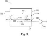
- Fig. 3 depicts an embodiment (not forming part of the invention) where only capacitance changes between the membrane 304 and the upper portion of the inductor 310 are used to detect and monitor the movements of the membrane 304. Similar to the previous embodiments the upper portion of the inductor 310 may be considered an electrode which forms a capacitor in combination with the membrane 304. Thus, the principle depicted in Fig. 3 may be applied to standard receivers as no changes are to be made to such standard receiver. In the embodiment depicted in Fig. 3 the inductor 310 is biased with up to 20 V in case the receiver is manufactured as a MEMS device. The signal from the inductor 310 is passed through the pre-amp 311 prior to being processed further.
- the embodiment depicted in Fig. 3 comprises a grounded housing 301 having a sound outlet 302, a membrane 304 suspended or fixated at 309, a moving armature 303 mechanically hinged at 308, two permanent magnets 306, 307 and a rigid connection 305 between the moving armature 303 and the membrane 304.
- Fig. 4 depicts an embodiment (not forming part of the invention) where a sensor 408, such as an accelerometer, is attached to the membrane 404 in order to detect and monitor the movements thereof.
- the signal from the sensor 408 is communicated to external equipment via a wireless transmission link.
- a wired connection can be used as well.
- the embodiment depicted in Fig. 4 comprises a grounded housing 401 having a sound outlet 402, a membrane 404 suspended or fixated at 410, a moving armature 403 mechanically hinged at 409, two permanent magnets 406, 407 and a rigid connection 405 between the moving armature 403 and the membrane 404.
- Fig. 5 depicts an embodiment (not forming part of the invention) where only capacitance changes between shock plates 511, 512 are used to detect and monitor the movements of the membrane 504.
- the shock plates 511, 512 which are secured to respective permanent magnets 507, 506, are provided for limiting the movements of the moving armature 503 and they may be manufactured by a suitable metal or alternatively, as a laminated structure of for example plastic and metal, where the metal is biased. As the moving armature 503 moves up and down due to corresponding movements of the membrane 504 the capacitance between the shock plates 511, 512 will change. If the biased shock plates 511, 512 are connected to a differential amplifier 513 the movements of the membrane 504 monitored.
- the signal from the differential amplifier 513 may be passed on for further processing.
- the embodiment depicted in Fig. 5 comprises a grounded housing 501 having a sound outlet 502, a membrane 504 suspended or fixated at point 509, a moving armature 503 mechanically hinged at 508, two permanent magnets 506, 507, an inductor 510 and a rigid connection 505 between the moving armature 503 and the membrane 504.
Claims (5)
- Schallerzeuger (112) für ein Hörgerät, wobei der Schallerzeuger (112) Folgendes umfasst:- eine bewegliche Membran (116), die mit Masse verbunden ist,- einen Motor mit beweglichem Anker zum Antreiben der beweglichen Membran (116) als Reaktion auf ein ankommendes elektrisches Signal, wobei ein Anker (115) des Motors mit beweglichem Anker über eine mechanische Verbindung (117) starr mit der beweglichen Membran (116) verbunden ist, und- eine Anordnung, die keinen Teil des Motors mit beweglichem Anker bildet, zum Erkennen von Bewegungen der beweglichen Membran (116),dadurch gekennzeichnet, dass die Anordnung zum Erkennen von Bewegungen der beweglichen Membran (116) Folgendes umfasst:- ein Paar von Elektroden (120, 121), die auf entgegengesetzten Seiten der beweglichen Membran (116) angeordnet sind, wobei jede der Elektroden (120, 121) einen Kondensator mit der beweglichen Membran (116) bildet, wobei sich die Kapazitäten der Kondensatoren mit den Entfernungen zwischen den jeweiligen Elektroden (120, 121) und der beweglichen Membran (116) verändern und wobei die Elektroden (120, 121) elektrisch vorgespannte oder Elektretelektroden sind und wobei die Elektroden (120, 121) geringfügig in entgegengesetzten Richtungen abgewinkelt/gekippt sind, um der Oberfläche der beweglichen Membran (116) zu folgen, wenn sie sich in einer verschobenen Position befindet, und- einen Differenzverstärker (122) zum Verarbeiten von Spannungsveränderungen, die sich aus Kapazitätsveränderungen der zwei Kondensatoren ergeben.
- Schallerzeuger nach Anspruch 1, wobei der Motor mit beweglichem Anker eine oder mehrere Induktionsspulen (126) umfasst, die um wenigstens einen Teil des beweglichem Ankers (115) des Motors gewickelt sind.
- Hörgerät, das einen Schallerzeuger nach einem der vorhergehenden Ansprüche umfasst, wobei das Hörgerät eine Hörhilfe umfasst, die ausgewählt ist aus der Gruppe, die aus Folgendem besteht: Hinter-dem-Ohr, Im-Ohr, Im-Gehörgang, Unsichtbar-im-Gehörgang und Vollständig-im-Gehörgang
- Verfahren zum Erkennen von Bewegungen einer beweglichen Membran (116) eines Schallerzeugers (112) für ein Hörgerät, wobei der Schallerzeuger (112) die bewegliche Membran (116), die mit Masse verbunden ist, einen Motor mit beweglichem Anker zum Antreiben der beweglichen Membran (116) als Reaktion auf ein ankommendes elektrisches Signal, wobei ein Anker (115) des Motors mit beweglichem Anker über eine mechanische Verbindung (117) starr mit der beweglichen Membran (116) verbunden ist, und eine Anordnung, die keinen Teil des Motors mit beweglichem Anker bildet, zum Erkennen von Bewegungen der beweglichen Membran (116) umfasst, wobei die Anordnung zum Erkennen von Bewegungen der beweglichen Membran (116) ein Paar von Elektroden (120, 121) umfasst, die auf entgegengesetzten Seiten der beweglichen Membran (116) angeordnet sind, wobei jede der Elektroden (120, 121) einen Kondensator mit der beweglichen Membran (116) bildet, wobei sich die Kapazitäten der Kondensatoren mit den Entfernungen zwischen den jeweiligen Elektroden (120, 121) und der beweglichen Membran (116) verändern und wobei die Elektroden (120, 121) elektrisch vorgespannte oder Elektretelektroden sind und wobei die Elektroden (120, 121) geringfügig in entgegengesetzten Richtungen abgewinkelt/gekippt sind, um der Oberfläche der beweglichen Membran (116) zu folgen, wenn sie sich in einer verschobenen Position befindet, wobei das Verfahren die folgenden Schritte umfasst:- Erzeugen, unter Verwendung der Anordnung zum Erkennen von Bewegungen der beweglichen Membran (116), elektrischer Signale, die Bewegungen der beweglichen Membran (116) darstellen,- Verarbeiten der elektrischen Signale, die Bewegungen der beweglichen Membran (116) darstellen, unter Verwendung eines Differenzverstärkers (122).
- Verfahren nach Anspruch 4, wobei die elektrischen Signale ein elektrisches Signal umfassen, das ein Maß für die Kapazitäten ist, die zwischen der beweglichen Membran (116) und den Elektroden (120, 121) gebildet werden.
Priority Applications (4)
| Application Number | Priority Date | Filing Date | Title |
|---|---|---|---|
| EP20215607.1A EP3826326A1 (de) | 2016-09-12 | 2016-09-12 | Empfänger mit integrierter membranbewegungsdetektion |
| EP16188330.1A EP3293985B1 (de) | 2016-09-12 | 2016-09-12 | Hörer mit integrierter membranbewegungserkennung |
| DK16188330.1T DK3293985T3 (da) | 2016-09-12 | 2016-09-12 | Lydgiver med integreret detektering af membranbevægelse |
| US15/697,965 US11070921B2 (en) | 2016-09-12 | 2017-09-07 | Receiver with integrated membrane movement detection |
Applications Claiming Priority (1)
| Application Number | Priority Date | Filing Date | Title |
|---|---|---|---|
| EP16188330.1A EP3293985B1 (de) | 2016-09-12 | 2016-09-12 | Hörer mit integrierter membranbewegungserkennung |
Related Child Applications (2)
| Application Number | Title | Priority Date | Filing Date |
|---|---|---|---|
| EP20215607.1A Division-Into EP3826326A1 (de) | 2016-09-12 | 2016-09-12 | Empfänger mit integrierter membranbewegungsdetektion |
| EP20215607.1A Division EP3826326A1 (de) | 2016-09-12 | 2016-09-12 | Empfänger mit integrierter membranbewegungsdetektion |
Publications (2)
| Publication Number | Publication Date |
|---|---|
| EP3293985A1 EP3293985A1 (de) | 2018-03-14 |
| EP3293985B1 true EP3293985B1 (de) | 2021-03-24 |
Family
ID=56896458
Family Applications (2)
| Application Number | Title | Priority Date | Filing Date |
|---|---|---|---|
| EP16188330.1A Active EP3293985B1 (de) | 2016-09-12 | 2016-09-12 | Hörer mit integrierter membranbewegungserkennung |
| EP20215607.1A Pending EP3826326A1 (de) | 2016-09-12 | 2016-09-12 | Empfänger mit integrierter membranbewegungsdetektion |
Family Applications After (1)
| Application Number | Title | Priority Date | Filing Date |
|---|---|---|---|
| EP20215607.1A Pending EP3826326A1 (de) | 2016-09-12 | 2016-09-12 | Empfänger mit integrierter membranbewegungsdetektion |
Country Status (3)
| Country | Link |
|---|---|
| US (1) | US11070921B2 (de) |
| EP (2) | EP3293985B1 (de) |
| DK (1) | DK3293985T3 (de) |
Family Cites Families (84)
| Publication number | Priority date | Publication date | Assignee | Title |
|---|---|---|---|---|
| NL1009544C2 (nl) | 1998-07-02 | 2000-01-10 | Microtronic Nederland Bv | Stelsel bestaande uit een microfoon en een voorversterker. |
| AU5617599A (en) | 1998-09-24 | 2000-04-10 | Microtronic A/S | A hearing aid adapted for discrete operation |
| WO2000027166A2 (en) * | 1998-11-02 | 2000-05-11 | Sarnoff Corporation | Transducer concepts for hearing aids and other devices |
| US7706561B2 (en) | 1999-04-06 | 2010-04-27 | Sonion Nederland B.V. | Electroacoustic transducer with a diaphragm and method for fixing a diaphragm in such transducer |
| NL1011733C1 (nl) | 1999-04-06 | 2000-10-09 | Microtronic Nederland Bv | Elektroakoestische transducent met een membraan en werkwijze voor het bevestigen van een membraan in een dergelijke transducent. |
| NL1011778C1 (nl) | 1999-04-13 | 2000-10-16 | Microtronic Nederland Bv | Microfoon voor een hoorapparaat en een hoorapparaat voorzien van een dergelijke microfoon. |
| AU5060800A (en) | 1999-06-10 | 2001-01-02 | Techtronic A/S | Encoder |
| US6522762B1 (en) | 1999-09-07 | 2003-02-18 | Microtronic A/S | Silicon-based sensor system |
| EP1305977B1 (de) | 2000-06-30 | 2007-06-06 | Sonion Nederland B.V. | Ein mikrofonzusammenbau |
| US7181035B2 (en) | 2000-11-22 | 2007-02-20 | Sonion Nederland B.V. | Acoustical receiver housing for hearing aids |
| TW510139B (en) | 2001-01-26 | 2002-11-11 | Kirk Acoustics As | An electroacoustic transducer and a coil and a magnet circuit therefor |
| US6831577B1 (en) | 2001-02-02 | 2004-12-14 | Sonion A/S | Sigma delta modulator having enlarged dynamic range due to stabilized signal swing |
| WO2002073792A2 (en) | 2001-03-09 | 2002-09-19 | Techtronic A/S | An electret condensor microphone preamplifier that is insensitive to leakage currents at the input |
| US7088839B2 (en) | 2001-04-04 | 2006-08-08 | Sonion Nederland B.V. | Acoustic receiver having improved mechanical suspension |
| US7136496B2 (en) | 2001-04-18 | 2006-11-14 | Sonion Nederland B.V. | Electret assembly for a microphone having a backplate with improved charge stability |
| US7062058B2 (en) | 2001-04-18 | 2006-06-13 | Sonion Nederland B.V. | Cylindrical microphone having an electret assembly in the end cover |
| US6859542B2 (en) | 2001-05-31 | 2005-02-22 | Sonion Lyngby A/S | Method of providing a hydrophobic layer and a condenser microphone having such a layer |
| US7227968B2 (en) | 2001-06-25 | 2007-06-05 | Sonion Roskilde A/S | Expandsible Receiver Module |
| DE60238657D1 (de) | 2001-07-20 | 2011-02-03 | Sonion As | Schalter/Lautstärkenregelung für ein Hörgerät |
| US6788796B1 (en) | 2001-08-01 | 2004-09-07 | The Research Foundation Of The State University Of New York | Differential microphone |
| US7239714B2 (en) | 2001-10-09 | 2007-07-03 | Sonion Nederland B.V. | Microphone having a flexible printed circuit board for mounting components |
| WO2003032347A1 (en) | 2001-10-10 | 2003-04-17 | Sonionmicrotronic A/S | A digital pulse generator assembly |
| WO2003032345A1 (en) | 2001-10-10 | 2003-04-17 | Sonionmicrotronic A/S | A multifunctional switch |
| WO2003047309A1 (en) | 2001-11-30 | 2003-06-05 | Sonion A/S | A high efficiency driver for miniature loudspeakers |
| KR20040081470A (ko) | 2002-01-25 | 2004-09-21 | 소니온 호르젠스 에이/에스 | 집적된 코일을 구비한 플랙서블 다이어프램 |
| US7190803B2 (en) * | 2002-04-09 | 2007-03-13 | Sonion Nederland Bv | Acoustic transducer having reduced thickness |
| DE10228157B3 (de) * | 2002-06-24 | 2004-01-08 | Siemens Audiologische Technik Gmbh | Hörgerätesystem mit einem Hörgerät und einer externen Prozessoreinheit |
| US6888408B2 (en) | 2002-08-27 | 2005-05-03 | Sonion Tech A/S | Preamplifier for two terminal electret condenser microphones |
| US7072482B2 (en) | 2002-09-06 | 2006-07-04 | Sonion Nederland B.V. | Microphone with improved sound inlet port |
| AU2002951326A0 (en) * | 2002-09-11 | 2002-09-26 | Innotech Pty Ltd | Communication apparatus and helmet |
| US8280082B2 (en) | 2002-10-08 | 2012-10-02 | Sonion Nederland B.V. | Electret assembly for a microphone having a backplate with improved charge stability |
| US7292876B2 (en) | 2002-10-08 | 2007-11-06 | Sonion Nederland B.V. | Digital system bus for use in low power instruments such as hearing aids and listening devices |
| US7142682B2 (en) | 2002-12-20 | 2006-11-28 | Sonion Mems A/S | Silicon-based transducer for use in hearing instruments and listening devices |
| DE60320632T2 (de) | 2002-12-23 | 2009-06-04 | Sonion Roskilde A/S | Eingekapselter Hörer mit einem expandierbaren Mittel wie z.B. einem Ballon |
| US7008271B2 (en) | 2003-02-20 | 2006-03-07 | Sonion Roskilde A/S | Female connector assembly with a displaceable conductor |
| ATE329362T1 (de) | 2003-03-04 | 2006-06-15 | Sonion Roskilde As | Kombinierter roller und tastschalter |
| US7466835B2 (en) | 2003-03-18 | 2008-12-16 | Sonion A/S | Miniature microphone with balanced termination |
| DE10316287B3 (de) | 2003-04-09 | 2004-07-15 | Siemens Audiologische Technik Gmbh | Richtmikrofon |
| ATE401759T1 (de) | 2003-05-01 | 2008-08-15 | Sonion Roskilde As | Einsatzmodul für miniatur-hörhilfegerät |
| US7012200B2 (en) | 2004-02-13 | 2006-03-14 | Sonion Roskilde A/S | Integrated volume control and switch assembly |
| WO2005115053A1 (en) | 2004-05-14 | 2005-12-01 | Sonion Nederland B.V. | Dual diaphragm electroacoustic transducer |
| EP1599067B1 (de) | 2004-05-21 | 2013-05-01 | Epcos Pte Ltd | Detektion und Kontrolle des Membrankollaps in einem Kondensatormikrofon |
| EP1613125A3 (de) | 2004-07-02 | 2008-10-22 | Sonion Nederland B.V. | Mikrofonaufbau mit magnetisch aktivierbarem Element zur Signal-Umschaltung und Fieldsanzeige |
| US7460681B2 (en) | 2004-07-20 | 2008-12-02 | Sonion Nederland B.V. | Radio frequency shielding for receivers within hearing aids and listening devices |
| EP1626612A3 (de) | 2004-08-11 | 2009-05-06 | Sonion Nederland B.V. | Montagestruktur eines Hörhilfegerätsmikrofons und Montageverfahren dafür |
| DK1638366T3 (en) | 2004-09-20 | 2015-12-14 | Sonion Nederland Bv | microphone device |
| US7415121B2 (en) | 2004-10-29 | 2008-08-19 | Sonion Nederland B.V. | Microphone with internal damping |
| US8379899B2 (en) | 2004-11-01 | 2013-02-19 | Sonion Nederland B.V. | Electro-acoustical transducer and a transducer assembly |
| DK1684544T3 (da) | 2005-01-10 | 2011-06-14 | Sonion Nederland Bv | Montering af elektroakustisk transducer i hus for personlige kommunikationsanordninger |
| EP1742506B1 (de) | 2005-07-06 | 2013-05-22 | Epcos Pte Ltd | Mikrofonanordnung mit P-typ Vorverstärkerseingangsstufe |
| US7899203B2 (en) | 2005-09-15 | 2011-03-01 | Sonion Nederland B.V. | Transducers with improved viscous damping |
| EP1814356B1 (de) | 2006-01-26 | 2010-03-24 | Sonion MEMS A/S | Elastomerschild für Miniaturmikrofone |
| EP1852882A3 (de) | 2006-05-01 | 2009-07-29 | Sonion Roskilde A/S | Multifunktionale Steuerung |
| US8170249B2 (en) | 2006-06-19 | 2012-05-01 | Sonion Nederland B.V. | Hearing aid having two receivers each amplifying a different frequency range |
| DK1895811T3 (en) | 2006-08-28 | 2016-08-29 | Sonion Nederland Bv | Several speakers with a common acoustic tube |
| EP1926344B1 (de) | 2006-11-21 | 2011-10-19 | Sonion A/S | Zweiteilige Steckverbinderbaugruppe |
| DE112007003083B4 (de) | 2006-12-22 | 2019-05-09 | Tdk Corp. | Mikrofonbaugruppe mit Unterfüllmittel mit niedrigem Wärmeausdehnungskoeffizienten |
| DK1962551T3 (da) | 2007-02-20 | 2014-07-14 | Sonion Nederland Bv | Lydgiver med bevægeligt armatur |
| US8391534B2 (en) | 2008-07-23 | 2013-03-05 | Asius Technologies, Llc | Inflatable ear device |
| US8160290B2 (en) | 2007-09-04 | 2012-04-17 | Sonion A/S | Electroacoustic transducer having a slotted terminal structure for connection to a flexible wire, and an assembly of the same |
| EP2046072A3 (de) * | 2007-10-01 | 2009-11-04 | Sonion Nederland B.V. | Mikrofonanordnung mit Ersatzteil |
| DK2071866T3 (en) | 2007-12-14 | 2017-07-24 | Sonion As | Removable earpiece sound system with spring control |
| US8189804B2 (en) | 2007-12-19 | 2012-05-29 | Sonion Nederland B.V. | Sound provider adapter to cancel out noise |
| US8852251B2 (en) * | 2008-03-31 | 2014-10-07 | Cochlear Limited | Mechanical fixation system for a prosthetic device |
| US8259976B2 (en) | 2008-04-02 | 2012-09-04 | Sonion Nederland B.V. | Assembly comprising a sound emitter and two sound detectors |
| US8101876B2 (en) | 2008-04-22 | 2012-01-24 | Sonion Aps | Electro-mechanical pulse generator |
| US8331595B2 (en) | 2008-06-11 | 2012-12-11 | Sonion Nederland Bv | Hearing instrument with improved venting and miniature loudspeaker therefore |
| EP2166779B1 (de) | 2008-09-18 | 2019-05-22 | Sonion Nederland B.V. | Vorrichtung zur Ausgabe von Tönen, die mehrere Empfänger und einen gemeinsamen Ausgabekanal umfasst |
| AU2009337971B2 (en) | 2009-01-23 | 2012-08-02 | Widex A/S | System, method and hearing aids for in situ occlusion effect measurement |
| US8526651B2 (en) | 2010-01-25 | 2013-09-03 | Sonion Nederland Bv | Receiver module for inflating a membrane in an ear device |
| US8313336B2 (en) | 2010-02-01 | 2012-11-20 | Sonion A/S | Assembly comprising a male and a female plug member, a male plug member and a female plug member |
| US7946890B1 (en) | 2010-02-02 | 2011-05-24 | Sonion A/S | Adapter for an electronic assembly |
| EP2393312B1 (de) | 2010-06-07 | 2014-08-13 | Sonion A/S | Verfahren zur Formung eines Verbinders für ein Hörgerät |
| EP2393311A1 (de) | 2010-06-07 | 2011-12-07 | Sonion A/S | Cerumenfilter für Hörgeräte |
| EP2408221B1 (de) | 2010-07-16 | 2016-09-28 | Sonion Nederland B.V. | Hörgerät |
| US8712084B2 (en) | 2010-12-07 | 2014-04-29 | Sonion Nederland Bv | Motor assembly |
| DK2466915T3 (en) * | 2010-12-14 | 2016-06-27 | Sonion Nederland Bv | Multilayer luminaire for a movable luminaire receiver |
| DK2469705T3 (en) | 2010-12-21 | 2016-03-07 | Sonion Nederland Bv | Generating a supply voltage from the output of a class-D amplifier |
| US8792672B2 (en) | 2011-03-21 | 2014-07-29 | Sonion Nederland B.V. | Moving armature receiver assemblies with vibration suppression |
| US9283376B2 (en) * | 2011-05-27 | 2016-03-15 | Cochlear Limited | Interaural time difference enhancement strategy |
| EP2552128A1 (de) | 2011-07-29 | 2013-01-30 | Sonion Nederland B.V. | Doppelkapsel-Richtmikrofon |
| US9055380B2 (en) | 2011-11-28 | 2015-06-09 | Sonion Nederland B.V. | Method for producing a tube for a hearing aid |
| DK2608576T3 (en) | 2011-12-21 | 2020-03-30 | Sonion Nederland Bv | An apparatus and a method for providing sound |
| US8971554B2 (en) | 2011-12-22 | 2015-03-03 | Sonion Nederland Bv | Hearing aid with a sensor for changing power state of the hearing aid |
-
2016
- 2016-09-12 DK DK16188330.1T patent/DK3293985T3/da active
- 2016-09-12 EP EP16188330.1A patent/EP3293985B1/de active Active
- 2016-09-12 EP EP20215607.1A patent/EP3826326A1/de active Pending
-
2017
- 2017-09-07 US US15/697,965 patent/US11070921B2/en active Active
Non-Patent Citations (1)
| Title |
|---|
| None * |
Also Published As
| Publication number | Publication date |
|---|---|
| DK3293985T3 (da) | 2021-06-21 |
| EP3293985A1 (de) | 2018-03-14 |
| US20180077501A1 (en) | 2018-03-15 |
| US11070921B2 (en) | 2021-07-20 |
| EP3826326A1 (de) | 2021-05-26 |
Similar Documents
| Publication | Publication Date | Title |
|---|---|---|
| US10869141B2 (en) | Audio device with valve state management | |
| KR20170132180A (ko) | 듀얼 다이어프램 마이크로폰 | |
| US8199943B2 (en) | Hearing apparatus with automatic switch-off and corresponding method | |
| US20050084128A1 (en) | Directional microphone | |
| CN106797520B (zh) | 操作助听器系统的方法和助听器系统 | |
| US20080095391A1 (en) | Magnetic Sensor for a Transducer | |
| WO2009145096A1 (ja) | 音声入力装置及びその製造方法、並びに、情報処理システム | |
| CN101453684A (zh) | 声音输入装置 | |
| JP5166117B2 (ja) | 音声入力装置及びその製造方法、並びに、情報処理システム | |
| CN101543089A (zh) | 语音输入装置及其制造方法、信息处理系统 | |
| JP5872687B2 (ja) | アナログデータ処理ユニットを備えるアセンブリ及び当該アセンブリを使用する方法 | |
| EP2223534B1 (de) | Mems-mikrofon | |
| CN112040356B (zh) | 一种麦克风和扬声器集成系统 | |
| CN110907029B (zh) | 振动感测装置的校准方法 | |
| WO2008062848A1 (fr) | Dispositif d'entrée vocale, procédé de production de ce dernier et système de traitement d'informations | |
| CN204669605U (zh) | 声学设备 | |
| CN107079228B (zh) | 操作助听器系统的方法和助听器系统 | |
| EP3293985B1 (de) | Hörer mit integrierter membranbewegungserkennung | |
| WO2021053883A1 (ja) | ピックアップセンサ及び骨伝導スピーカ | |
| US20120224722A1 (en) | Method for driving a condenser microphone | |
| EP4285603A1 (de) | Schall- und vibrationssensor | |
| CN110099342B (zh) | 送话装置 | |
| JP4212635B1 (ja) | 音声入力装置及びその製造方法、並びに、情報処理システム | |
| KR200412624Y1 (ko) | 진동 센서 | |
| JP4863981B2 (ja) | 補聴装置の制御方法 |
Legal Events
| Date | Code | Title | Description |
|---|---|---|---|
| PUAI | Public reference made under article 153(3) epc to a published international application that has entered the european phase |
Free format text: ORIGINAL CODE: 0009012 |
|
| STAA | Information on the status of an ep patent application or granted ep patent |
Free format text: STATUS: THE APPLICATION HAS BEEN PUBLISHED |
|
| AK | Designated contracting states |
Kind code of ref document: A1 Designated state(s): AL AT BE BG CH CY CZ DE DK EE ES FI FR GB GR HR HU IE IS IT LI LT LU LV MC MK MT NL NO PL PT RO RS SE SI SK SM TR |
|
| AX | Request for extension of the european patent |
Extension state: BA ME |
|
| STAA | Information on the status of an ep patent application or granted ep patent |
Free format text: STATUS: REQUEST FOR EXAMINATION WAS MADE |
|
| 17P | Request for examination filed |
Effective date: 20180914 |
|
| RBV | Designated contracting states (corrected) |
Designated state(s): AL AT BE BG CH CY CZ DE DK EE ES FI FR GB GR HR HU IE IS IT LI LT LU LV MC MK MT NL NO PL PT RO RS SE SI SK SM TR |
|
| STAA | Information on the status of an ep patent application or granted ep patent |
Free format text: STATUS: EXAMINATION IS IN PROGRESS |
|
| 17Q | First examination report despatched |
Effective date: 20190416 |
|
| GRAP | Despatch of communication of intention to grant a patent |
Free format text: ORIGINAL CODE: EPIDOSNIGR1 |
|
| STAA | Information on the status of an ep patent application or granted ep patent |
Free format text: STATUS: GRANT OF PATENT IS INTENDED |
|
| RIC1 | Information provided on ipc code assigned before grant |
Ipc: H04R 25/00 20060101ALN20201022BHEP Ipc: H04R 19/01 20060101ALN20201022BHEP Ipc: H04R 19/04 20060101AFI20201022BHEP Ipc: H04R 11/02 20060101ALN20201022BHEP |
|
| INTG | Intention to grant announced |
Effective date: 20201123 |
|
| GRAS | Grant fee paid |
Free format text: ORIGINAL CODE: EPIDOSNIGR3 |
|
| GRAA | (expected) grant |
Free format text: ORIGINAL CODE: 0009210 |
|
| STAA | Information on the status of an ep patent application or granted ep patent |
Free format text: STATUS: THE PATENT HAS BEEN GRANTED |
|
| AK | Designated contracting states |
Kind code of ref document: B1 Designated state(s): AL AT BE BG CH CY CZ DE DK EE ES FI FR GB GR HR HU IE IS IT LI LT LU LV MC MK MT NL NO PL PT RO RS SE SI SK SM TR |
|
| REG | Reference to a national code |
Ref country code: GB Ref legal event code: FG4D |
|
| REG | Reference to a national code |
Ref country code: CH Ref legal event code: EP |
|
| REG | Reference to a national code |
Ref country code: IE Ref legal event code: FG4D |
|
| REG | Reference to a national code |
Ref country code: AT Ref legal event code: REF Ref document number: 1375728 Country of ref document: AT Kind code of ref document: T Effective date: 20210415 Ref country code: DE Ref legal event code: R096 Ref document number: 602016054724 Country of ref document: DE |
|
| REG | Reference to a national code |
Ref country code: DK Ref legal event code: T3 Effective date: 20210618 |
|
| REG | Reference to a national code |
Ref country code: LT Ref legal event code: MG9D |
|
| PG25 | Lapsed in a contracting state [announced via postgrant information from national office to epo] |
Ref country code: NO Free format text: LAPSE BECAUSE OF FAILURE TO SUBMIT A TRANSLATION OF THE DESCRIPTION OR TO PAY THE FEE WITHIN THE PRESCRIBED TIME-LIMIT Effective date: 20210624 Ref country code: HR Free format text: LAPSE BECAUSE OF FAILURE TO SUBMIT A TRANSLATION OF THE DESCRIPTION OR TO PAY THE FEE WITHIN THE PRESCRIBED TIME-LIMIT Effective date: 20210324 Ref country code: GR Free format text: LAPSE BECAUSE OF FAILURE TO SUBMIT A TRANSLATION OF THE DESCRIPTION OR TO PAY THE FEE WITHIN THE PRESCRIBED TIME-LIMIT Effective date: 20210625 Ref country code: FI Free format text: LAPSE BECAUSE OF FAILURE TO SUBMIT A TRANSLATION OF THE DESCRIPTION OR TO PAY THE FEE WITHIN THE PRESCRIBED TIME-LIMIT Effective date: 20210324 Ref country code: BG Free format text: LAPSE BECAUSE OF FAILURE TO SUBMIT A TRANSLATION OF THE DESCRIPTION OR TO PAY THE FEE WITHIN THE PRESCRIBED TIME-LIMIT Effective date: 20210624 |
|
| PG25 | Lapsed in a contracting state [announced via postgrant information from national office to epo] |
Ref country code: SE Free format text: LAPSE BECAUSE OF FAILURE TO SUBMIT A TRANSLATION OF THE DESCRIPTION OR TO PAY THE FEE WITHIN THE PRESCRIBED TIME-LIMIT Effective date: 20210324 Ref country code: RS Free format text: LAPSE BECAUSE OF FAILURE TO SUBMIT A TRANSLATION OF THE DESCRIPTION OR TO PAY THE FEE WITHIN THE PRESCRIBED TIME-LIMIT Effective date: 20210324 Ref country code: LV Free format text: LAPSE BECAUSE OF FAILURE TO SUBMIT A TRANSLATION OF THE DESCRIPTION OR TO PAY THE FEE WITHIN THE PRESCRIBED TIME-LIMIT Effective date: 20210324 |
|
| REG | Reference to a national code |
Ref country code: NL Ref legal event code: MP Effective date: 20210324 |
|
| REG | Reference to a national code |
Ref country code: AT Ref legal event code: MK05 Ref document number: 1375728 Country of ref document: AT Kind code of ref document: T Effective date: 20210324 |
|
| PG25 | Lapsed in a contracting state [announced via postgrant information from national office to epo] |
Ref country code: NL Free format text: LAPSE BECAUSE OF FAILURE TO SUBMIT A TRANSLATION OF THE DESCRIPTION OR TO PAY THE FEE WITHIN THE PRESCRIBED TIME-LIMIT Effective date: 20210324 |
|
| PG25 | Lapsed in a contracting state [announced via postgrant information from national office to epo] |
Ref country code: EE Free format text: LAPSE BECAUSE OF FAILURE TO SUBMIT A TRANSLATION OF THE DESCRIPTION OR TO PAY THE FEE WITHIN THE PRESCRIBED TIME-LIMIT Effective date: 20210324 Ref country code: CZ Free format text: LAPSE BECAUSE OF FAILURE TO SUBMIT A TRANSLATION OF THE DESCRIPTION OR TO PAY THE FEE WITHIN THE PRESCRIBED TIME-LIMIT Effective date: 20210324 Ref country code: LT Free format text: LAPSE BECAUSE OF FAILURE TO SUBMIT A TRANSLATION OF THE DESCRIPTION OR TO PAY THE FEE WITHIN THE PRESCRIBED TIME-LIMIT Effective date: 20210324 Ref country code: AT Free format text: LAPSE BECAUSE OF FAILURE TO SUBMIT A TRANSLATION OF THE DESCRIPTION OR TO PAY THE FEE WITHIN THE PRESCRIBED TIME-LIMIT Effective date: 20210324 Ref country code: SM Free format text: LAPSE BECAUSE OF FAILURE TO SUBMIT A TRANSLATION OF THE DESCRIPTION OR TO PAY THE FEE WITHIN THE PRESCRIBED TIME-LIMIT Effective date: 20210324 |
|
| PG25 | Lapsed in a contracting state [announced via postgrant information from national office to epo] |
Ref country code: PT Free format text: LAPSE BECAUSE OF FAILURE TO SUBMIT A TRANSLATION OF THE DESCRIPTION OR TO PAY THE FEE WITHIN THE PRESCRIBED TIME-LIMIT Effective date: 20210726 Ref country code: PL Free format text: LAPSE BECAUSE OF FAILURE TO SUBMIT A TRANSLATION OF THE DESCRIPTION OR TO PAY THE FEE WITHIN THE PRESCRIBED TIME-LIMIT Effective date: 20210324 Ref country code: SK Free format text: LAPSE BECAUSE OF FAILURE TO SUBMIT A TRANSLATION OF THE DESCRIPTION OR TO PAY THE FEE WITHIN THE PRESCRIBED TIME-LIMIT Effective date: 20210324 Ref country code: RO Free format text: LAPSE BECAUSE OF FAILURE TO SUBMIT A TRANSLATION OF THE DESCRIPTION OR TO PAY THE FEE WITHIN THE PRESCRIBED TIME-LIMIT Effective date: 20210324 Ref country code: IS Free format text: LAPSE BECAUSE OF FAILURE TO SUBMIT A TRANSLATION OF THE DESCRIPTION OR TO PAY THE FEE WITHIN THE PRESCRIBED TIME-LIMIT Effective date: 20210724 |
|
| REG | Reference to a national code |
Ref country code: DE Ref legal event code: R097 Ref document number: 602016054724 Country of ref document: DE |
|
| PG25 | Lapsed in a contracting state [announced via postgrant information from national office to epo] |
Ref country code: ES Free format text: LAPSE BECAUSE OF FAILURE TO SUBMIT A TRANSLATION OF THE DESCRIPTION OR TO PAY THE FEE WITHIN THE PRESCRIBED TIME-LIMIT Effective date: 20210324 Ref country code: AL Free format text: LAPSE BECAUSE OF FAILURE TO SUBMIT A TRANSLATION OF THE DESCRIPTION OR TO PAY THE FEE WITHIN THE PRESCRIBED TIME-LIMIT Effective date: 20210324 |
|
| PLBE | No opposition filed within time limit |
Free format text: ORIGINAL CODE: 0009261 |
|
| STAA | Information on the status of an ep patent application or granted ep patent |
Free format text: STATUS: NO OPPOSITION FILED WITHIN TIME LIMIT |
|
| PG25 | Lapsed in a contracting state [announced via postgrant information from national office to epo] |
Ref country code: SI Free format text: LAPSE BECAUSE OF FAILURE TO SUBMIT A TRANSLATION OF THE DESCRIPTION OR TO PAY THE FEE WITHIN THE PRESCRIBED TIME-LIMIT Effective date: 20210324 |
|
| 26N | No opposition filed |
Effective date: 20220104 |
|
| REG | Reference to a national code |
Ref country code: BE Ref legal event code: MM Effective date: 20210930 |
|
| PG25 | Lapsed in a contracting state [announced via postgrant information from national office to epo] |
Ref country code: IS Free format text: LAPSE BECAUSE OF FAILURE TO SUBMIT A TRANSLATION OF THE DESCRIPTION OR TO PAY THE FEE WITHIN THE PRESCRIBED TIME-LIMIT Effective date: 20210724 Ref country code: MC Free format text: LAPSE BECAUSE OF FAILURE TO SUBMIT A TRANSLATION OF THE DESCRIPTION OR TO PAY THE FEE WITHIN THE PRESCRIBED TIME-LIMIT Effective date: 20210324 |
|
| PG25 | Lapsed in a contracting state [announced via postgrant information from national office to epo] |
Ref country code: LU Free format text: LAPSE BECAUSE OF NON-PAYMENT OF DUE FEES Effective date: 20210912 Ref country code: IE Free format text: LAPSE BECAUSE OF NON-PAYMENT OF DUE FEES Effective date: 20210912 Ref country code: BE Free format text: LAPSE BECAUSE OF NON-PAYMENT OF DUE FEES Effective date: 20210930 |
|
| PGFP | Annual fee paid to national office [announced via postgrant information from national office to epo] |
Ref country code: GB Payment date: 20220804 Year of fee payment: 7 |
|
| PG25 | Lapsed in a contracting state [announced via postgrant information from national office to epo] |
Ref country code: IT Free format text: LAPSE BECAUSE OF FAILURE TO SUBMIT A TRANSLATION OF THE DESCRIPTION OR TO PAY THE FEE WITHIN THE PRESCRIBED TIME-LIMIT Effective date: 20210324 |
|
| PGFP | Annual fee paid to national office [announced via postgrant information from national office to epo] |
Ref country code: CH Payment date: 20221001 Year of fee payment: 7 |
|
| PG25 | Lapsed in a contracting state [announced via postgrant information from national office to epo] |
Ref country code: HU Free format text: LAPSE BECAUSE OF FAILURE TO SUBMIT A TRANSLATION OF THE DESCRIPTION OR TO PAY THE FEE WITHIN THE PRESCRIBED TIME-LIMIT; INVALID AB INITIO Effective date: 20160912 |
|
| PG25 | Lapsed in a contracting state [announced via postgrant information from national office to epo] |
Ref country code: CY Free format text: LAPSE BECAUSE OF FAILURE TO SUBMIT A TRANSLATION OF THE DESCRIPTION OR TO PAY THE FEE WITHIN THE PRESCRIBED TIME-LIMIT Effective date: 20210324 |
|
| PGFP | Annual fee paid to national office [announced via postgrant information from national office to epo] |
Ref country code: FR Payment date: 20230821 Year of fee payment: 8 Ref country code: DK Payment date: 20230914 Year of fee payment: 8 Ref country code: DE Payment date: 20230808 Year of fee payment: 8 |
|
| PG25 | Lapsed in a contracting state [announced via postgrant information from national office to epo] |
Ref country code: MK Free format text: LAPSE BECAUSE OF FAILURE TO SUBMIT A TRANSLATION OF THE DESCRIPTION OR TO PAY THE FEE WITHIN THE PRESCRIBED TIME-LIMIT Effective date: 20210324 |
|
| REG | Reference to a national code |
Ref country code: CH Ref legal event code: PL |