EP3293461A1 - Installation for providing hot water circulating in buildings - Google Patents
Installation for providing hot water circulating in buildings Download PDFInfo
- Publication number
- EP3293461A1 EP3293461A1 EP17405015.3A EP17405015A EP3293461A1 EP 3293461 A1 EP3293461 A1 EP 3293461A1 EP 17405015 A EP17405015 A EP 17405015A EP 3293461 A1 EP3293461 A1 EP 3293461A1
- Authority
- EP
- European Patent Office
- Prior art keywords
- hot water
- line
- cold water
- flow direction
- water
- Prior art date
- Legal status (The legal status is an assumption and is not a legal conclusion. Google has not performed a legal analysis and makes no representation as to the accuracy of the status listed.)
- Withdrawn
Links
- XLYOFNOQVPJJNP-UHFFFAOYSA-N water Substances O XLYOFNOQVPJJNP-UHFFFAOYSA-N 0.000 title claims abstract description 358
- 238000009434 installation Methods 0.000 title claims description 14
- 238000005070 sampling Methods 0.000 claims abstract description 15
- 238000003303 reheating Methods 0.000 claims abstract description 7
- 238000010438 heat treatment Methods 0.000 claims description 26
- 238000011144 upstream manufacturing Methods 0.000 claims description 12
- 238000013517 stratification Methods 0.000 claims description 6
- 238000000605 extraction Methods 0.000 claims description 4
- 239000007787 solid Substances 0.000 claims description 3
- 238000002485 combustion reaction Methods 0.000 claims description 2
- 238000013021 overheating Methods 0.000 claims description 2
- 230000005611 electricity Effects 0.000 claims 1
- 238000013461 design Methods 0.000 description 6
- 230000006978 adaptation Effects 0.000 description 1
- 230000015572 biosynthetic process Effects 0.000 description 1
- 238000004140 cleaning Methods 0.000 description 1
- 238000010276 construction Methods 0.000 description 1
- 238000001514 detection method Methods 0.000 description 1
- 238000004519 manufacturing process Methods 0.000 description 1
- 230000005855 radiation Effects 0.000 description 1
- 238000010079 rubber tapping Methods 0.000 description 1
- 230000009885 systemic effect Effects 0.000 description 1
- 238000012546 transfer Methods 0.000 description 1
- 238000013022 venting Methods 0.000 description 1
Images


Classifications
-
- F—MECHANICAL ENGINEERING; LIGHTING; HEATING; WEAPONS; BLASTING
- F24—HEATING; RANGES; VENTILATING
- F24D—DOMESTIC- OR SPACE-HEATING SYSTEMS, e.g. CENTRAL HEATING SYSTEMS; DOMESTIC HOT-WATER SUPPLY SYSTEMS; ELEMENTS OR COMPONENTS THEREFOR
- F24D17/00—Domestic hot-water supply systems
- F24D17/0078—Recirculation systems
-
- F—MECHANICAL ENGINEERING; LIGHTING; HEATING; WEAPONS; BLASTING
- F24—HEATING; RANGES; VENTILATING
- F24D—DOMESTIC- OR SPACE-HEATING SYSTEMS, e.g. CENTRAL HEATING SYSTEMS; DOMESTIC HOT-WATER SUPPLY SYSTEMS; ELEMENTS OR COMPONENTS THEREFOR
- F24D19/00—Details
- F24D19/10—Arrangement or mounting of control or safety devices
- F24D19/1006—Arrangement or mounting of control or safety devices for water heating systems
- F24D19/1051—Arrangement or mounting of control or safety devices for water heating systems for domestic hot water
Definitions
- the present invention relates to a system for the provision of hot water in buildings, the hot water is conveyed in a continuous cycle in the circulation network to ensure at the sampling points as immediate as possible hot water readiness.
- the hot water readiness is usually in the range of about 55 ° C.
- thermostatic mixer JRGUMAT
- JRGUMAT thermostatic mixer
- the additional function of this valve is to constantly maintain the circulation in the hot water circuit for the purpose of continuous hot water readiness.
- temperature control in combination with circulation pumps to control the systemic excess temperatures.
- the invention has the object to provide a more efficient system for the provision of hot water in buildings. This with guaranteed immediate hot water readiness at the sampling points and thereby minimized circulation losses, so that the water heater no longer need to be oversized and ultimately the efficiency of the entire system is significantly improved.
- Another task is to develop the system both for temperature controllable heat sources - such as boilers, heat pumps or remote district heating - as well as in connection with solar thermal systems.
- a connected to the hot water circulation pipe and arranged between the hot water boiler and the tapping points control device is intended to, from the control device via the hot water circulation line inflowing water a first subset in the hot water supply line and to pass a remaining second subset into the water heater for reheating.
- the partial quantity ratio with the first partial amount is set substantially greater than the second partial quantity, preferably in the range of 90%: 10%.
- the settings and dimensions of the system are dimensioned so that in the operating condition of the system in the at least one water heater a stable zone stratification with a low existing cold water zone, a subsequent mixing water zone and a hot water zone formed above is obtained.
- the control device has a hot water line, to the inflow side, the hot water supply line and the outflow side, the hot water supply line are connected.
- the control device further has a circulation line which internally divides the control device at a circulation fork into a sub-line and a warm-up line. On the inflow side of the circulation line, the hot water circulation line is connected, and the warm-up line is connected to the outflow side of the hot water return line.
- control device may also have a cold water line, to the inflow side of the cold water inlet line and outflow a cold water supply line are connected.
- the cold water supply line branches into a refill line leading to the water heater and into a safety line leading to a safety unit.
- the safety unit has a safety valve that reacts to overpressure and flows into a drain.
- a pump with delivery direction to the sub-strand and to the warm-up line is installed.
- a first hot water meter, a backflow preventer open in the flow direction, and a first balancing valve are installed as a flow restrictor in succession in the flow direction.
- a second hot water meter, a backflow preventer open in the flow direction and a second balancing valve are installed as a flow restrictor in succession in the flow direction.
- a temperature controller is positioned in front of the second hot water meter.
- the temperature controller has the function, at a target temperature set by the two balancing valves initially set partial ratio first subset: second subset falls below the setpoint temperature of incoming water via the hot water circulation line to increase the second subset and reduce the second subset when exceeded.
- the sub-string leads the hot water strand inflowing at an opening in the hot water line.
- backflow preventer In the cold water line open in the flow direction backflow preventer is arranged.
- the hot water line In the hot water line is, contrary to the flow direction, installed upstream of the confluence open in the flow direction backflow preventer.
- a shut-off valve In the cold water line, viewed against the flow direction, a shut-off valve is arranged in front of the backflow preventer.
- a shut-off valve is installed in front of the pump.
- thermometer In the cold water line, between the backflow preventer and the shut-off valve, a cold water meter is installed.
- a thermometer In the hot water line, viewed in the direction of flow, sitting in front of the shut-off a thermometer.
- a vent valve In the hot water line, viewed against the flow direction, a vent valve is connected in front of the backflow preventer.
- another thermometer In the circulation line, viewed against the flow direction, another thermometer is installed in front of the shut-off valve.
- a shut-off valve is arranged in the cold water line, contrary to the flow direction, before the cold water branch.
- a shut-off valve is installed in front of the thermal mixer.
- a shut-off valve is installed in front of the pump.
- a cold water meter is installed in front of the pump.
- a thermometer In the hot water line, viewed in the direction of flow, sitting in front of the shut-off a thermometer.
- a vent valve In the hot water line, contrary to the flow direction, is in front of the Thermomixer a vent valve connected.
- another thermometer is installed in front of the shut-off valve.
- the plant may comprise a heat source of the first type, in the form of a boiler based on oil, gas, solids or electric energy, or a district heating connection or a heat pump, and a heat source of the second type based on solar thermal or photovoltaic. Both heat sources are energy suppliers for at least a first water heater or other water heater.
- the at least one hot water conditioner or also the other hot water conditioner each have a first and a second heating coil, one of which is connected to the heat source of the first type and the other with the heat source of the second type.
- control device is designed in a compact device form with modular and installable according to individual customer requirements fittings.
- FIGS. 1A and 1B are identical to FIGS. 1A and 1B.
- This system comprises a heat source 1 of the first type, a first hot water conditioner 2, a control device 3 and, by way of example, only one removal point 0 , wherein in practice a plurality of removal points 0 are usually present.
- the structural design of the plant will now be described, as viewed from the heat source 1 .
- the first type of heat source 1 may be a boiler - based on oil, gas or solids or electric energy - or a district heating connection or a heat pump and can be set in its temperature.
- a charging line 71 extends to a first boiler connection 21 on the hot water conditioner 2 .
- the heating register 28 installed internally of the hot water conditioner 2 , which leads to the second boiler connection 22 on the hot water conditioner 2 , from which the return line 72 extends to the second source connection 12 of the heat source 1 .
- a circulation of the heat source 1 is made possible by the heating coil 28 , which thus causes the heating of the water filling in the water heater 2 .
- the thermometer 20 is provided for temperature detection of the water filling.
- the hot water line 35 extends, namely from the fifth control connection 305 to the second control connection 302 .
- the hot water supply line 5 runs in the direction of removal point 0 .
- the circulation connection 56 is installed at which the hot water supply line 5 on the one hand continues to the withdrawal point 0 and on the other hand branches off as hot water circulation line 6 , which opens at the third control port 303 in the control device 3 .
- a circulation line 36 which internally the control device 3 at a circulation fork 367 divides, namely on the one hand as a sub-strand 36 'at the junction 357 leads into the hot water line 35 and on the other hand as branching off from the circulation line 36 Aufnicastrang 37th running to the sixth control terminal 306 .
- the hot water return line 84 extends to the fourth boiler connection 24 .
- cold water is fed into the cold water line 34 extending through the control device 3 via the cold water inlet line 4 and the first control connection 301 , which leads to the fourth control connection 304 of the control device 3 and continues from here as a cold water supply line 41 .
- the cold water supply line 41 divides at the cold water fork 47 , namely on the one hand into the safety line 41 "leading to the safety unit 9 and on the other hand into the refill line 41 'leading to the fifth boiler connection 25 of the hot water conditioner 2.
- the safety unit 9 consists of a safety valve 90 with discharge in FIG a drain 91.
- the refill line 41 'branches off on the one hand to the fifth boiler connection 25 and on the other hand to a drain valve 29 for emptying the hot water conditioner 2 during service work.
- the cold water inlet line 4 is brought to its first control terminal 301 .
- the first control port 301 following - quasi in the flow direction - is installed in the cold water line 34 first a shut-off valve 341 , behind which a cold water meter 342 sits.
- a backflow preventer 343 is inserted between the cold water meter 342 and the fourth control port 304 - here.
- the hot water supply line 5 extends from its second control connection 302 .
- a thermometer 350 is installed in the hot-water line 35 , behind which there is a shut-off valve 351 , which first follows the junction 357 and then a backflow preventer 353 .
- a vent valve 354 Before the fifth control connection 305 - to which the hot water supply line 83 is brought - is connected to the hot water line 35, a vent valve 354 .
- the hot water circulation line 6 is brought to its third control port 303 .
- the third control connection 303 -quasi in the direction of flow-a thermometer 360 which is followed by a shut-off valve 361 and then a pump 365 , first sits in the circulation line 36 .
- the circulation fork 367 from the one hand, the sub-strand 36 'continues to the junction 357 on the hot water line 35 and on the other hand, the warm-up strand 37 branches off and leads to the sixth control terminal 306 .
- the hot water return line 84 extends.
- a first hot water meter 362 is first installed in the sub-string 36 ', followed by a backflow preventer 363 and then a balancing valve 366 as a flow restrictor before the sub-string 36 ' leads into the warm water line 35 at the junction 357 .
- a temperature controller 377 is installed first, followed by a second hot water meter 372 , then a backflow preventer 363 and finally a balancing valve 376 as a flow restrictor.
- shut-off valves 341 , 351 , 361 are used to interrupt the flow in the respective strand 34 , 35 , 36 and are closed, for example, when cleaning the hot water boiler 2 or when servicing the pump 365 .
- these shut-off valves 341 , 351 , 361 are installed inside the control device 3 . It would be possible to install the shut-off valves 341 , 351 , 361 alternatively in the cold water inlet line 4 , the hot water supply line 5 and the hot water circulation line . 6
- the thermometers 350 , 360 could be used outside of the control device 3 in the hot water supply line 5 and the hot water circulation line 6 . Only in the fully populated version will provide the cold water meter 342 , where the inflowing volume of cold water and thus the consumption of hot water is readable. Equally dispensable would be the temperature controller 377 .
- the backflow preventer 343 , 353 , 363 , 373 have the task to block the paths against the respective predetermined flow direction, which is required in the event of overpressure - eg due to thermal expansion - is required.
- the first and second hot water meters 362 , 372 serve to measure the flow rates behind the circulation fork 367 in the sub-string 36 'or in the warm-up string 37 .
- the measured values of the flow rates are required in order to set the desired ratio of subsets M 1 : M 2 by means of the two balancing valves 366 , 376 , which differs from the warm water circulation dividing at the circulation bifurcation 367 via the partial line 36 'as the first subset M 1 of the junction 357 or via the warm-up line 37 as a second subset M 2 of the hot water return line 84 flow.
- a partial flow ratio with M 1 >> M 2 is set at the control device 3 for the flow, for example with M 1 : M 2 in the range of 90%: 10%.
- M 1 : M 2 90%: 10% so 90% of flowing in the hot water circulation line 6 as the first subset M 1 via the control device 3 again fed directly into the hot water supply line 5 , while the remaining 10% as a second subset M 2 on the hot water return line 84 for reheating in the water heater 2 reach.
- the flowing in the hot water circulation pipe 6 water had cooled by heat losses in the pipe network below the water temperature required at the sampling points 0 .
- the control device 3 has the temperature controller 377 useful for dynamic readjustment.
- FIGS. 2A and 2B are identical to FIGS. 2A and 2B.
- the plant of the current variant now also comprises a heat source 1 'of the second type, which is based on solar thermal energy, for the existing heat source 1 of the first type. Due to the sometimes extremely fluctuating solar radiation - depending on the time of day, weather and season - you always have to provide heat sources 1.1 'of both types for a system for providing hot water. Both heat sources 1 , 1 ' are connected to the first hot water conditioner 2 .
- the charging line 71 and the return line 72 of the heat source 1 of the first type are connected to the associated first heating coil 28 in the hot water boiler 2 via the two boiler connections 21 , 22 .
- This first heating register 28 is positioned above the second heating register 28 ' .
- the heat source 1 'of the second type is based on solar thermal energy and has the first source connection 11' from which the charging line 71 ' extends.
- the return line 72' is introduced.
- the second heating register 28 ' is connected to the associated charging line 71' and return line 72 ' via the two boiler connections 21' , 22 ' . With sufficiently recoverable solar energy, it will be advantageous to use only the heat source 1 'of the second type for heating the hot water conditioner 2 , only otherwise the heat source 1 of the first type in addition or alone.
- the balancing valve 366 in the partial line 36 'in the flow direction is followed by a thermal mixer 358 installed in the hot water line 35 between the shut-off valve 351 and the venting valve 354 . From the thermal mixer 358 , a descending line 36 " extends to the cold water branch 347 , which lies on the cold water line 34 between the cold water meter 342 and the backflow preventer 343.
- the backflow preventer 353 previously installed in the hot water line 35 in FIG. 1B is now in the descending line 36" between the Thermomixer 358 and the cold water branch 347 implemented.
- the backflow preventer 353 and the thermal mixer 358 ensure the admixture of cold water to the inflow from the hot water supply line 83 and the partial line 36 '. By lowering the temperature of the setpoint in the hot water supply line 5 is reached.
- a partial quantity ratio with M 1 >> M 2 is advantageously set again, preferably with M 1 : M 2 in the range of 90%: 10%. Also otherwise, the structural design and the function of the system according to pair of figures 2A and 2B correspond to the preceding embodiment with pair of figures 1A and 1B.
- the plant now comprises a heat source 1 of the first type, a first and a second hot water conditioner 2 , 2 ' , a control device 3 and by way of example a removal point 0 .
- the one heat source 1 is connected in parallel to both hot water conditioners 2 , 2 ' , the identically each a thermometer 20 , the five boiler connections 21-25 , the heating coil 28 and the drain valve 29 have.
- the parallel connection of two existing water heaters 2,2 ' results in a more branched course for the refill line 41' , the first charge line 71 and the first return line 72 .
- the refilling line 41 ' coming from the cold water fork 47 leads via the cross connection 48' or via the T connection 48 to the respective fifth boiler connection 25 of the two hot water conditioners 2, 2 '.
- the cross-connection 48 ' and the T-connection 48 also serve to install a respective drain valve 29 for the respectively associated hot water conditioner 2', 2.
- the first charging line 71 leads to the respective first boiler connection 21 of the relevant water heater 2,2 ' .
- the first heating coil 28 installed in the respective hot water conditioner 2,2 'is connected.
- the first return line 72 extends from the respective second boiler connection 22 , which is connected to the first heating coil 28 present in the relevant hot water conditioner 2, 2 , to the first heat source 1 .
- the hot water supply line 83 runs from the third boiler connections 23 of both hot water conditioners 2, 2 ' to the fifth control connection 305 of the control device 3 .
- the hot water return line 84 passes from the sixth control connection 306 of the control device 3 to the respective fourth boiler connection 24 of the relevant domestic water heater 2,2 ' .
- a partial quantity ratio with M 1 >> M 2 can be set, preferably with M 1 : M 2 in the range of 90%: 10% (see FIG. 1 B) , Also otherwise correspond to the structural design and the function of the system in FIG. 3 the first embodiment with pair of figures 1A and 1B.
- the refill line 41 ' is brought in via the cross connection 48' or via the T connection 48 to the fifth boiler connections 25 of the two hot water conditioners 2, 2 ' .
- the hot water supply line 83 in turn extends from both water heaters 2,2 ' combined to the control device 3 , while the hot water return line 84 passes from the control device 3 to both hot water conditioner 2,2' .
- the first charge line 71 leads to the first boiler connection 21 of the relevant hot water conditioner 2, 2 ' , in which the respective first heating register 28 is installed.
- the first return line 72 comes from the respective second boiler connection 22 of the relevant domestic water heater 2,2 ' , in which the first heating coils 28 are installed, and extends to the second source connection 12 of the first heat source 1 .
- This complex system construction also makes it possible to set a partial flow ratio with M 1 >> M 2 , preferably with M 1 : M 2 in the range of 90%: 10%, for the water arriving at the control device 3 through the hot water circulation line 6 .
- M 1 the partial flow ratio
- M 2 the advantages of the dynamic readjustment for an adequate adaptation of the partial quantity ratio M 1 : M 2 are additionally usable.
- This system structure with the alternatively or together operable heat sources 1,1 ' and parallel connected water heaters 2,2' is energetically particularly efficient.
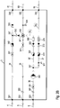
- This figure illustrates the three-part zone stratification in a hot water conditioner 2 connected to a heat source 1 of the first type.
- the zone stratification is maintained, so by vortex formation no mixing between the existing below in the water heater 2 cold water zone KWz, the next mixed water zone MWz and above formed hot water zone WWz .
- From the bottom of the water heater 2 to about half the height of the heating coil 28 extends the cold water zone KWz, while the mixed water zone MWz adjusts to above the heating register 28, near the fourth boiler port 24 with the incoming hot water return line 84 .
- the remaining upper area in the hot water conditioner 2 takes the hot water zone WWz .
Landscapes
- Engineering & Computer Science (AREA)
- Physics & Mathematics (AREA)
- Thermal Sciences (AREA)
- Chemical & Material Sciences (AREA)
- Combustion & Propulsion (AREA)
- Mechanical Engineering (AREA)
- General Engineering & Computer Science (AREA)
- Domestic Hot-Water Supply Systems And Details Of Heating Systems (AREA)
- Heat-Pump Type And Storage Water Heaters (AREA)
Abstract
Die Anlage zur Bereitstellung von in Gebäuden in Zirkulation umlaufendem Warmwasser umfasst eine Wärmequelle (1,1') als Energielieferant für zumindest einen Warmwasseraufbereiter (2,2'), eine Vielzahl von Entnahmestellen (0) für das bereitgestellte Warmwasser, eine Kaltwassereinlaufleitung (4) zur Einspeisung von Kaltwasser in die Anlage, eine Warmwasserzulaufleitung (5) zur Heranführung von Warmwasser an die Entnahmestellen (0) und eine Warmwasserzirkulationsleitung (6), die vor den Entnahmestellen (0) abzweigt. Eine an die Warmwasserzirkulationsleitung (6) angeschlossene und zwischen dem Warmwasseraufbereiter ( 2,2' ) und den Entnahmestellen (0) angeordnete Steuervorrichtung (3) ist dazu bestimmt, vom der Steuervorrichtung (3) über die Warmwasserzirkulationsleitung (6) zufliessenden Wasser eine erste Teilmenge ( M 1 ) in die Warmwasserzulaufleitung (5) und eine verbleibende zweite Teilmenge ( M 2 ) zur Nachwärmung in den Warmwasseraufbereiter ( 2,2' ) zu leiten. Vorteilhaft ist das Teilmengenverhältnis mit ( M 1 ) >> ( M 2 ) eingestellt, wobei vorzugsweise das Teilmengenverhältnis mit ( M 1 ) : ( M 2 ) im Bereich von 90% : 10% liegt.The system for providing circulating hot water in buildings comprises a heat source (1,1 ') as an energy supplier for at least one water heater (2,2'), a plurality of taps (0) for the provided hot water, a cold water inlet pipe (4) for feeding cold water into the system, a hot water supply line (5) for the supply of hot water to the sampling points (0) and a hot water circulation line (6), which branches off before the sampling points (0). A control device (3) connected to the hot water circulation line (6) and arranged between the hot water conditioner (2,2 ') and the removal points (0) is intended to supply a first subset of water flowing to the control device (3) via the hot water circulation line (6) (M 1) in the hot water supply line (5) and a remaining second subset (M 2) for reheating in the hot water boiler (2,2 ') to pass. Advantageously, the partial quantity ratio is set with (M 1) >> (M 2), wherein preferably the partial quantity ratio with (M 1): (M 2) is in the range of 90%: 10%.
Description
Die vorliegende Erfindung betrifft eine Anlage zur Bereitstellung von Warmwasser in Gebäuden, wobei das Warmwasser in ständigem Kreislauf im Zirkulationsnetz gefördert wird, um an den Entnahmestellen eine möglichst sofortige Warmwasserbereitschaft zu gewährleisten. Als Gebäude kommen grössere Wohnhäuser und Verwaltungsgebäude in Betracht. Die Warmwasserbereitschaft liegt üblicherweise im Bereich von ca. 55°C.The present invention relates to a system for the provision of hot water in buildings, the hot water is conveyed in a continuous cycle in the circulation network to ensure at the sampling points as immediate as possible hot water readiness. As buildings larger residential buildings and administrative buildings are considered. The hot water readiness is usually in the range of about 55 ° C.
Auf der Homepage www.jrg.ch wird der Thermomischer "JRGUMAT" präsentiert, der zum Einbau in Warmwasserkreisläufen bestimmt ist, um den sicheren Verbrühungsschutz zu gewährleisten. Die Zusatzfunktion dieser Armatur ist, im Warmwasserkreislauf die Zirkulation beständig aufrechtzuerhalten zwecks stetiger Warmwasserbereitschaft. Insbesondere bei thermischen Solaranlagen ist bekannt, zur Beherrschung der systembedingten Übertemperaturen Temperaturregler in Kombination mit Zirkulationspumpen einzusetzen.On the homepage www.jrg.ch the thermostatic mixer "JRGUMAT" is presented, which is intended for installation in hot water circuits to ensure safe protection against scalding. The additional function of this valve is to constantly maintain the circulation in the hot water circuit for the purpose of continuous hot water readiness. In particular, in thermal solar systems is known to use temperature control in combination with circulation pumps to control the systemic excess temperatures.
In der
Der Nachteil dieser bisherigen Lösungen besteht darin, dass aufgrund der erheblichen Zirkulationsverluste die Warmwasseraufbereiter und die Wärmequellen in Gestalt von Heizkesseln, Wärmepumpen oder thermischen Solaranlagen oder als herangeführte Fernwärme grosszügig dimensioniert werden müssen, so dass die Gesamtanlage bei dem hohen geräte-technischen Aufwand nur einen an sich unbefriedigenden Wirkungsgrad zwischen eingesetzter und nutzbarer Energie hat.The disadvantage of these previous solutions is that due to the significant circulation losses, the water heater and the heat sources in the form of boilers, heat pumps or solar thermal systems or must be generously dimensioned as zoomed district heating, so that the overall system with the high equipment-technical effort has only a per se unsatisfactory efficiency between used and usable energy.
Angesichts des bisherigen Standes der Technik liegt der Erfindung die Aufgabe zugrunde, eine effizientere Anlage zur Bereitstellung von Warmwasser in Gebäuden zu schaffen. Dies mit Gewährleistung einer möglichst sofortigen Warmwasserbereitschaft an den Entnahmestellen und dabei minimierten Zirkulationsverlusten, so dass die Warmwasseraufbereiter nicht mehr überdimensioniert werden müssen und letztlich damit der Wirkungsgrad der gesamten Anlage wesentlich verbessert wird. Eine weitere Aufgabe besteht darin, die Anlage sowohl für in der Temperatur steuerbare Wärmequellen - wie Heizkessel, Wärmepumpen oder herangeführte Fernwärme - als auch in Verbindung mit Solarthermieanlagen zu entwickeln. Schliesslich ist es Aufgabe der Erfindung, die Montage der Anlage möglichst einfach und zeiteffizient zu gestalten.In view of the prior art, the invention has the object to provide a more efficient system for the provision of hot water in buildings. This with guaranteed immediate hot water readiness at the sampling points and thereby minimized circulation losses, so that the water heater no longer need to be oversized and ultimately the efficiency of the entire system is significantly improved. Another task is to develop the system both for temperature controllable heat sources - such as boilers, heat pumps or remote district heating - as well as in connection with solar thermal systems. Finally, it is an object of the invention to make the installation of the system as simple and time-efficient.
Die Anlage zur Bereitstellung von in Gebäuden in Zirkulation umlaufendem Warmwasser umfasst:
- eine Wärmequelle als Energielieferant für zumindest einen Warmwasseraufbereiter;
- eine Vielzahl von Entnahmestellen für das bereitgestellte Warmwasser;
- eine Kaltwassereinlaufleitung zur Einspeisung von Kaltwasser in die Anlage;
- eine Warmwasserzulaufleitung zur Heranführung von Warmwasser an die Entnahmestellen; und
- eine Warmwasserzirkulationsleitung, die vor den Entnahmestellen abzweigt.
- a heat source as an energy supplier for at least one water heater;
- a plurality of extraction points for the provided hot water;
- a cold water inlet pipe for feeding cold water into the plant;
- a hot water supply line for bringing hot water to the sampling points; and
- a hot water circulation pipe, which branches off in front of the sampling points.
Eine an die Warmwasserzirkulationsleitung angeschlossene und zwischen dem Warmwasseraufbereiter und den Entnahmestellen angeordnete Steuervorrichtung ist dazu bestimmt, vom der Steuervorrichtung über die Warmwasserzirkulationsleitung zufliessenden Wasser eine erste Teilmenge in die Warmwasserzulaufleitung und eine verbleibende zweite Teilmenge zur Nachwärmung in den Warmwasseraufbereiter zu leiten.A connected to the hot water circulation pipe and arranged between the hot water boiler and the tapping points control device is intended to, from the control device via the hot water circulation line inflowing water a first subset in the hot water supply line and to pass a remaining second subset into the water heater for reheating.
Zwischen dem Warmwasseraufbereiter und der Steuervorrichtung verläuft eine jeweils beide verbindende Warmwasservorlaufleitung und Warmwasserrücklaufleitung. An der Steuervorrichtung ist das Teilmengenverhältnis mit erster Teilmenge wesentlich grösser als die zweite Teilmenge eingestellt, vorzugsweise im Bereich von 90% : 10%. Die Einstellungen und Dimensionierungen der Anlage sind so bemessen, dass man im Betriebszustand der Anlage in dem zumindest einen Warmwasseraufbereiter eine stabile Zonenschichtung mit einer zuunterst vorhandenen Kaltwasser-Zone, einer darüber folgenden Mischwasser-Zone und einer oben sich gebildeten Warmwasser-Zone erhält.Between the hot water conditioner and the control device runs both connecting hot water supply line and hot water return line. At the control device, the partial quantity ratio with the first partial amount is set substantially greater than the second partial quantity, preferably in the range of 90%: 10%. The settings and dimensions of the system are dimensioned so that in the operating condition of the system in the at least one water heater a stable zone stratification with a low existing cold water zone, a subsequent mixing water zone and a hot water zone formed above is obtained.
Nachstehend sind besonders vorteilhafte Details zur erfindungsgemässen Anlage genannt: In dem zumindest einen Warmwasseraufbereiter erstrecken sich:
- die Kaltwasser-Zone vom Boden des Warmwasseraufbereiters und darin aufwärts;
- die Warmwasser-Zone vom Bereich der in den Warmwasseraufbereiter einmündenden Warmwasserrücklaufleitung bis zum oberen Ende des Warmwasseraufbereiters; und
- die Mischwasser-Zone nimmt die Höhe zwischen der Kaltwasser-Zone und der Warmwasser-Zone ein.
- the cold water zone from the bottom of the boiler and up there;
- the hot water zone from the area of the hot water return line entering the boiler to the upper end of the boiler; and
- the mixing water zone occupies the height between the cold water zone and the hot water zone.
Zwischen dem Warmwasseraufbereiter und der Steuervorrichtung verläuft eine jeweils beide verbindende Warmwasservorlaufleitung und Warmwasserrücklaufleitung. Die Steuervorrichtung weist einen Warmwasserstrang auf, an den einströmseitig die Warmwasservorlaufleitung und ausströmseitig die Warmwasserzulaufleitung angeschlossen sind. Die Steuervorrichtung hat ferner einen Zirkulationsstrang, der sich intern der Steuervorrichtung an einer Zirkulationsgabelung in einen Teilstrang und einen Aufwärmestrang aufteilt. Einströmseitig an den Zirkulationsstrang ist die Warmwasserzirkulationsleitung angeschlossen, und der Aufwärmestrang ist ausströmseitig an die Warmwasserrücklaufleitung angeschlossen.Between the hot water conditioner and the control device runs both connecting hot water supply line and hot water return line. The control device has a hot water line, to the inflow side, the hot water supply line and the outflow side, the hot water supply line are connected. The control device further has a circulation line which internally divides the control device at a circulation fork into a sub-line and a warm-up line. On the inflow side of the circulation line, the hot water circulation line is connected, and the warm-up line is connected to the outflow side of the hot water return line.
Vorteilhaft kann die Steuervorrichtung auch einen Kaltwasserstrang besitzen, an den einströmseitig die Kaltwassereinlaufleitung und ausströmseitig eine Kaltwasservorlaufleitung angeschlossen sind. Die Kaltwasservorlaufleitung verzweigt sich in eine zum Warmwasseraufbereiter führende Nachfüllleitung und in eine zu einer Sicherheitseinheit führende Sicherheitsleitung. Die Sicherheitseinheit hat ein auf Überdruck reagierendes und in einen Ablauf strömendes Sicherheitsventil.Advantageously, the control device may also have a cold water line, to the inflow side of the cold water inlet line and outflow a cold water supply line are connected. The cold water supply line branches into a refill line leading to the water heater and into a safety line leading to a safety unit. The safety unit has a safety valve that reacts to overpressure and flows into a drain.
Im Zirkulationsstrang ist eine Pumpe mit Förderrichtung zum Teilstrang und zum Aufwärmestrang installiert. Im Teilstrang sind in Strömungsrichtung hintereinander ein erster Warmwasserzähler, ein in Strömungsrichtung offener Rückflussverhinderer und ein erstes Abgleichventil als Durchflussbegrenzer installiert. Im Aufwärmestrang sind in Strömungsrichtung hintereinander ein zweiter Warmwasserzähler, ein in Strömungsrichtung offener Rückflussverhinderer und ein zweites Abgleichventil als Durchflussbegrenzer eingebaut.In the circulation line, a pump with delivery direction to the sub-strand and to the warm-up line is installed. In the sub-string, a first hot water meter, a backflow preventer open in the flow direction, and a first balancing valve are installed as a flow restrictor in succession in the flow direction. In the warm-up strand, a second hot water meter, a backflow preventer open in the flow direction and a second balancing valve are installed as a flow restrictor in succession in the flow direction.
Im Aufwärmestrang ist, entgegen der Strömungsrichtung betrachtet, vor dem zweiten Warmwasserzähler ein Temperaturregler positioniert. Der Temperaturregler hat die Funktion, bei einer daran eingestellten Solltemperatur das mittels der beiden Abgleichventile zunächst fest eingestellte Teilmengenverhältnis erste Teilmenge : zweiter Teilmenge bei Unterschreitung der Solltemperatur des über die Warmwasserzirkulationsleitung ankommenden Wassers die zweite Teilmenge zu erhöhen und bei Überschreitung die zweite Teilmenge zu verringern.In the warm-up line, viewed against the flow direction, a temperature controller is positioned in front of the second hot water meter. The temperature controller has the function, at a target temperature set by the two balancing valves initially set partial ratio first subset: second subset falls below the setpoint temperature of incoming water via the hot water circulation line to increase the second subset and reduce the second subset when exceeded.
Der Teilstrang führt dem Warmwasserstrang zuströmend an einer Einmündung in den Warmwasserstrang. Im Kaltwasserstrang ist ein in Strömungsrichtung offener Rückflussverhinderer angeordnet. Im Warmwasserstrang ist, entgegen der Strömungsrichtung betrachtet, vor der Einmündung ein in Strömungsrichtung offener Rückflussverhinderer eingebaut. Im Kaltwasserstrang ist, entgegen der Strömungsrichtung betrachtet, vor dem Rücklussverhinderer eine Absperrarmatur angeordnet. Im Warmwasserstrang ist, in Strömungsrichtung betrachtet, vor der Einmündung eine Absperrarmatur eingebaut. Im Zirkulationsstrang ist, entgegen der Strömungsrichtung betrachtet, vor der Pumpe eine Absperrarmatur installiert.The sub-string leads the hot water strand inflowing at an opening in the hot water line. In the cold water line open in the flow direction backflow preventer is arranged. In the hot water line is, contrary to the flow direction, installed upstream of the confluence open in the flow direction backflow preventer. In the cold water line, viewed against the flow direction, a shut-off valve is arranged in front of the backflow preventer. In the hot water line is, viewed in the flow direction, in front of the Junction installed a shut-off valve. In the circulation line, viewed against the flow direction, a shut-off valve is installed in front of the pump.
Im Kaltwasserstrang, zwischen dem Rückflussverhinderer und der Absperrarmatur, ist ein Kaltwasserzähler eingebaut. Im Warmwasserstrang, in Strömungsrichtung betrachtet, sitzt vor der Absperrarmatur ein Thermometer. Im Warmwasserstrang, entgegen der Strömungsrichtung betrachtet, ist vor dem Rückflussverhinderer ein Entlüftungsventil angeschlossen. Im Zirkulationsstrang, entgegen der Strömungsrichtung betrachtet, ist vor der Absperrarmatur ein weiteres Thermometer installiert.In the cold water line, between the backflow preventer and the shut-off valve, a cold water meter is installed. In the hot water line, viewed in the direction of flow, sitting in front of the shut-off a thermometer. In the hot water line, viewed against the flow direction, a vent valve is connected in front of the backflow preventer. In the circulation line, viewed against the flow direction, another thermometer is installed in front of the shut-off valve.
Die Wärmequelle als Energielieferant für den zumindest einen Warmwasseraufbereiter kann auf Solarthermie, Photovoltaik, eingesetzter Wärmepumpe oder fossiler Verbrennung basieren; wobei dann:
- der Teilstrang in einen Thermomischer zuströmend einmündet, der im Warmwasserstrang eingebaut und zum Übertemperaturschutz bestimmt ist;
- sich von einer Kaltwasserabzweigung am Kaltwasserstrang ein in den Thermomischer Kaltwasser einleitender Absenkstrang erstreckt;
- im Kaltwasserstrang, entgegen der Strömungsrichtung betrachtet, vor der Kaltwasserabzweigung ein in Strömungsrichtung offener Rückflussverhinderer angeordnet ist; und
- im Absenkstrang ein in Strömungsrichtung offener Rückflussverhinderer angeordnet ist.
- the sub-branch flows into a thermomixer, which is installed in the hot-water line and intended for over-temperature protection;
- extending from a cold water branch at the cold water strand in the thermomixer cold water introductory Absenkstrang;
- in the cold water line, viewed against the flow direction, upstream of the cold water branch a flow-direction open backflow preventer is arranged; and
- in the Absenkstrang an open in the flow direction backflow preventer is arranged.
Bei der Nutzung der Solarthermie ist im Kaltwasserstrang, entgegen der Strömungsrichtung betrachtet, vor der Kaltwasserabzweigung eine Absperrarmatur angeordnet. Im Warmwasserstrang, in Strömungsrichtung betrachtet, ist vor dem Thermomischer eine Absperrarmatur eingebaut. Im Zirkulationsstrang, entgegen der Strömungsrichtung betrachtet, ist vor der Pumpe eine Absperrarmatur installiert. Im Kaltwasserstrang, zwischen der Kaltwasserabzweigung und der Absperrarmatur, ist ein Kaltwasserzähler eingebaut. Im Warmwasserstrang, in Strömungsrichtung betrachtet, sitzt vor der Absperrarmatur ein Thermometer. Im Warmwasserstrang, entgegen der Strömungsrichtung betrachtet, ist vor dem Thermomischer ein Entlüftungsventil angeschlossen. Im Zirkulationsstrang, entgegen der Strömungsrichtung betrachtet, ist vor der Absperrarmatur ein weiteres Thermometer installiert.When using the solar thermal energy, a shut-off valve is arranged in the cold water line, contrary to the flow direction, before the cold water branch. In the hot water line, viewed in the flow direction, a shut-off valve is installed in front of the thermal mixer. In the circulation line, viewed against the flow direction, a shut-off valve is installed in front of the pump. In the cold water line, between the cold water branch and the shut-off valve, a cold water meter is installed. In the hot water line, viewed in the direction of flow, sitting in front of the shut-off a thermometer. In the hot water line, contrary to the flow direction, is in front of the Thermomixer a vent valve connected. In the circulation line, viewed against the flow direction, another thermometer is installed in front of the shut-off valve.
Die Steuervorrichtung weist auf:
- einen ersten Steueranschluss zur Verbindung mit der Kaltwassereinlaufleitung und dem Kaltwasserstrang einströmseitig;
- einen zweiten Steueranschluss zur Verbindung mit der Warmwasserzulaufleitung und dem Warmwasserstrang ausströmseitig;
- einen dritten Steueranschluss zur Verbindung mit der Warmwasserzirkulationsleitung und dem Zirkulationsstrang einströmseitig;
- einen vierten Steueranschluss zur Verbindung mit dem Kaltwasserstrang ausströmseitig und der Kaltwasservorlaufleitung;
- einen fünften Steueranschluss zur Verbindung mit dem Warmwasserstrang einströmseitig und der Warmwasservorlaufleitung; und
- einen sechsten Steueranschluss zur Verbindung mit dem Aufwärmestrang ausströmseitig und der Warmwasserrücklaufleitung.
- a first control port for connection to the cold water inlet pipe and the cold water pipe upstream;
- a second control port for connection to the hot water supply line and the hot water line outflow;
- a third control port for connection to the hot water circulation line and the circulation line upstream;
- a fourth control port for connection to the cold water line outflow side and the cold water supply line;
- a fifth control port for connection to the hot water line upstream and the hot water supply line; and
- a sixth control port for connection to the warm up strand and the hot water return line.
Die Anlage kann eine Wärmequelle ersten Typs, in Gestalt eines Heizkessels - basierend auf Öl, Gas, Feststoffen oder Elektroenergie - oder eines Fernwärmeanschlusses oder einer Wärmepumpe, und eine Wärmequelle zweiten Typs, basierend auf Solarthermie oder Photovoltaik, aufweisen. Beide Wärmequellen sind Energielieferant für zumindest einen ersten Warmwasseraufbereiter oder auch weitere Warmwasseraufbereiter. Vorzugsweise der zumindest eine Warmwasseraufbereiter oder auch die weiteren Warmwasseraufbereiter besitzen jeweils ein erstes und ein zweites Heizregister, von denen eines mit der Wärmequelle ersten Typs und das andere mit der Wärmequelle zweiten Typs verbunden ist.The plant may comprise a heat source of the first type, in the form of a boiler based on oil, gas, solids or electric energy, or a district heating connection or a heat pump, and a heat source of the second type based on solar thermal or photovoltaic. Both heat sources are energy suppliers for at least a first water heater or other water heater. Preferably, the at least one hot water conditioner or also the other hot water conditioner each have a first and a second heating coil, one of which is connected to the heat source of the first type and the other with the heat source of the second type.
Die Anlage kann mehrere Warmwasseraufbereiter aufweisen, die einerseits zur Wärmequelle und andererseits zur Steuervorrichtung in Parallelschaltung angeordnet sind; wobei dann:
- die Nachfüllleitung an jeden der Warmwasseraufbereiter herangeführt ist;
- sich zwischen der Wärmequelle und den Warmwasseraufbereitern Ladeleitungen und Rücklaufleitungen erstrecken; und
- die jeweils an die Steuervorrichtung angeschlossene Warmwasservorlaufleitung und Warmwasserrücklaufleitung an jeden der Warmwasseraufbereiter herangeführt ist.
- the refill line is brought to each of the water heaters;
- extend between the heat source and the water heaters charging lines and return lines; and
- each connected to the control device hot water supply line and hot water return line is brought to each of the water heater.
Vorteilhaft für Herstellung, Lagerhaltung und Installation ist die Steuervorrichtung in kompakter Geräteform mit bausteinartig und gemäss individueller Kundenanforderung installierbaren Armaturen ausgebildet.Advantageous for manufacturing, warehousing and installation, the control device is designed in a compact device form with modular and installable according to individual customer requirements fittings.
Es zeigen:
- Figur 1A
- - eine Anlage zur Bereitstellung von in Gebäuden in Zirkulation umlaufendem Warmwasser mit einer Wärmequelle ersten Typs, einem ersten Warmwasseraufbereiter, einer Steuervorrichtung und beispielhaft einer Entnahmestelle, als schematische Darstellung;
- Figur 1B
- - die Steuervorrichtung aus
Figur 1A mit ihrem inneren Aufbau und den Anschlüssen; - Figur 2A
- - die Anlage gemäss
Figur 1A mit je einer Wärmequelle ersten und zweiten Typs, einem ersten Warmwasseraufbereiter, einer Steuervorrichtung und beispielhaft einer Entnahmestelle, als schematische Darstellung; - Figur 2B
- - die Steuervorrichtung aus
Figur 2A mit ihrem inneren Aufbau und den Anschlüssen; - Figur 3
- - eine Anlage gemäss
Figur 1A mit einer Wärmequelle ersten Typs, zwei parallel geschalteten Warmwasseraufbereitern, einer Steuervorrichtung und beispielhaft einer Entnahmestelle, als schematische Darstellung; Figur 4- - eine Anlage in kombinierter Konzeption der
Figuren 2A und3 , mit je einer Wärmequelle ersten und zweiten Typs, zwei parallel geschalteten Warmwasseraufbereitern, einer Steuervorrichtung und beispielhaft einer Entnahmestelle, als schematische Darstellung; und Figur 5- - einen Warmwasseraufbereiter mit der Zonenschichtung Warmwasser, Mischwasser und Kaltwasser in Verbindung mit einer Wärmequelle ersten Typs.
- Figure 1A
- - A system for providing circulating in buildings in hot water with a heat source of the first type, a first water heater, a control device and, for example, a sampling point, as a schematic representation;
- FIG. 1B
- - The controller off
Figure 1A with its internal structure and connections; - FIG. 2A
- - the system according to
Figure 1A with a respective heat source of the first and second type, a first hot water conditioner, a control device and, by way of example, a removal point, as a schematic representation; - FIG. 2B
- - The controller off
FIG. 2A with its internal structure and connections; - FIG. 3
- - an investment according to
Figure 1A with a heat source of the first type, two parallel warm water heaters, a control device and, for example, a sampling point, as a schematic representation; - FIG. 4
- a combined design concept of the
FIGS. 2A and3 , each with a heat source of the first and second type, two parallel hot water heaters, a control device and, for example, a sampling point, as a schematic representation; and - FIG. 5
- - A water heater with the zone stratification hot water, mixed water and cold water in conjunction with a heat source of the first type.
Mit Bezug auf die beiliegenden Zeichnungen erfolgt nachstehend die detaillierte Beschreibung eines Ausführungsbeispiels der erfindungsgemässen Anlage zur Bereitstellung von in Gebäuden in Zirkulation umlaufendem Warmwasser mit dazu geschaffenen Gestaltungsvarianten.With reference to the accompanying drawings, the detailed description of an embodiment of the inventive system for the provision of hot water circulating in buildings in circulation with design variants created thereto will be given below.
Für die gesamte weitere Beschreibung gilt folgende Festlegung. Sind in einer Figur zum Zweck zeichnerischer Eindeutigkeit Bezugsziffern enthalten, aber im unmittelbar zugehörigen Beschreibungstext nicht erläutert, so wird auf deren Erwähnung in vorangehenden oder nachfolgenden Figurenbeschreibungen Bezug genommen.The following definition applies to the entire further description. If reference numerals are included in a figure for the purpose of graphic clarity, but are not explained in the directly associated description text, reference is made to their mention in the preceding or following description of the figures.
Diese Anlage umfasst eine Wärmequelle 1 ersten Typs, einen ersten Warmwasseraufbereiter 2, eine Steuervorrichtung 3 und beispielhaft nur eine Entnahmestelle 0, wobei in der Praxis zumeist eine Vielzahl von Entnahmestellen 0 vorhanden sind. Der strukturelle Aufbau der Anlage wird nun, betrachtet von der Wärmequelle 1 aus, beschrieben. Der erste Typ einer Wärmequelle 1 kann ein Heizkessel - basierend auf Öl, Gas oder Feststoffen oder Elektroenergie - oder ein Fernwärmeanschluss oder eine Wärmepumpe sein und lässt sich in seiner Temperatur einstellen.This system comprises a
Vom ersten Quellenanschluss 11 der Wärmequelle 1 erstreckt sich eine Ladeleitung 71 hin zu einem ersten Boileranschluss 21 am Warmwasseraufbereiter 2.From the
An den ersten Boileranschluss 21 ist das intern des Warmwasseraufbereiters 2 installierte Heizregister 28 angeschlossen, das zum zweiten Boileranschluss 22 am Warmwasseraufbereiter 2 führt, von dem die Rücklaufleitung 72 zum zweiten Quellenanschluss 12 der Wärmequelle 1 verläuft. Damit wird eine Zirkulation von der Wärmequelle 1 durch das Heizregister 28 ermöglicht, welches somit die Erwärmung der Wasserfüllung im Warmwasseraufbereiter 2 bewirkt. Zur Temperaturerfassung der Wasserfüllung ist das Thermometer 20 vorgesehen.Connected to the
Aufgrund der Zielstellung, an den Entnahmestellen 0 ohne Verzögerung stets Warmwasser beziehen zu können, strömt Warmwasser, das im Warmwasseraufbereiter 2 aufgeheizt wurde, zunächst über den dritten Boileranschluss 23 durch eine Warmwasservorlaufleitung 83 zu einem fünften Steueranschluss 305 der Steuervorrichtung 3. Durch die Steuervorrichtung 3 hindurch erstreckt sich der Warmwasserstrang 35, nämlich vom fünften Steueranschluss 305 zum zweiten Steueranschluss 302. Vom zweiten Steueranschluss 302 verläuft die Warmwasserzufuhrleitung 5 in Richtung Entnahmestelle 0. Vor der Entnahmestelle 0 ist die Zirkulationsanbindung 56 installiert, an der sich die Warmwasserzufuhrleitung 5 einerseits hin zur Entnahmestelle 0 fortsetzt und andererseits als Warmwasserzirkulationsleitung 6 abzweigt, welche am dritten Steueranschluss 303 in die Steuervorrichtung 3 einmündet. Vom dritten Steueranschluss 303 erstreckt sich durch die Steuervorrichtung 3 ein Zirkulationsstrang 36, der sich intern der Steuervorrichtung 3 an einer Zirkulationsgabelung 367 aufteilt, nämlich einerseits als Teilstrang 36' an der Einmündung 357 in den Warmwasserstrang 35 führt und andererseits als vom Zirkulationsstrang 36 abzweigender Aufwärmestrang 37, der zum sechsten Steueranschluss 306 läuft. Vom sechsten Steueranschluss 306 erstreckt sich die Warmwasserrücklaufleitung 84 hin zum vierten Boileranschluss 24.Due to the objective of always be able to obtain hot water at the sampling points 0 warm water, which was heated in the
Bei Verbrauch von Warmwasser an einer der Entnahmestellen 0 wird über die Kaltwassereinlaufleitung 4 und den ersten Steueranschluss 301 Kaltwasser in den sich durch die Steuervorrichtung 3 erstreckenden Kaltwasserstrang 34 eingespeist, welcher zum vierten Steueranschluss 304 der Steuervorrichtung 3 führt und sich von hier als Kaltwasservorlaufleitung 41 fortsetzt. Die Kaltwasservorlaufleitung 41 teilt sich an der Kaltwassergabelung 47 auf, nämlich einerseits in die zur Sicherheitseinheit 9 führende Sicherheitsleitung 41" und andererseits in die zum fünften Boileranschluss 25 des Warmwasseraufbereiters 2 führende Nachfüllleitung 41'. Die Sicherheitseinheit 9 besteht aus einem auf Überdruck reagierenden Sicherheitsventil 90 mit Auslauf in einen Ablauf 91. An der T-Verbindung 48 zweigt die Nachfüllleitung 41' einerseits zum fünften Boileranschluss 25 ab und andererseits zu einem Entleerungsventil 29 zur Entleerung des Warmwasseraufbereiters 2 bei Servicearbeiten.When hot water is consumed at one of the extraction points 0 , cold water is fed into the
Nun werden der in der Steuervorrichtung 3 vorhandene Leitungsverlauf und die darin installierten Armaturen detailliert erörtert. Von ausserhalb der Steuervorrichtung 3 ist an ihren ersten Steueranschluss 301 die Kaltwassereinlaufleitung 4 herangeführt. Dem ersten Steueranschluss 301 folgend - quasi in Strömungsrichtung, - ist im Kaltwasserstrang 34 zuerst eine Absperrarmatur 341 eingebaut, hinter der ein Kaltwasserzähler 342 sitzt. Zwischen dem Kaltwasserzähler 342 und dem vierten Steueranschluss 304 - hier schliesst sich die Kaltwasservorlaufleitung 41 an - ist in den Kaltwasserstrang 34 ein Rückflussverhinderer 343 eingefügt.Now, the existing in the control device 3 line course and the fittings installed therein will be discussed in detail. From outside the control device 3 , the cold
Nach ausserhalb der Steuervorrichtung 3 erstreckt sich von ihrem zweiten Steueranschluss 302 die Warmwasserzulaufleitung 5. Dem zweiten Steueranschluss 302 folgend - quasi entgegen der Strömungsrichtung -, ist im Warmwasserstrang 35 zuerst ein Thermometer 350 eingebaut, hinter dem eine Absperrarmatur 351 sitzt, der zuerst die Einmündung 357 und dann ein Rückflussverhinderer 353 folgen. Vor dem fünften Steueranschluss 305 - an diesen ist die Warmwasservorlaufleitung 83 herangeführt - ist an den Warmwasserstrang 35 ein Entlüftungsventil 354 angeschlossen.To the outside of the control device 3 , the hot
Von ausserhalb der Steuervorrichtung 3 ist an ihren dritten Steueranschluss 303 die Warmwasserzirkulationsleitung 6 herangeführt. Dem dritten Steueranschluss 303 folgend - quasi in Strömungsrichtung -, sitzt im Zirkulationsstrang 36 zuerst ein Thermometer 360, dem eine Absperrarmatur 361 und dann eine Pumpe 365 folgen. Auf dem Zirkulationsstrang 36 liegt hinter der Pumpe 365 die Zirkulationsgabelung 367, von der sich einerseits der Teilstrang 36' hin zur Einmündung 357 am Warmwasserstrang 35 fortsetzt und andererseits der Aufwärmestrang 37 abzweigt und an den sechsten Steueranschluss 306 führt. Vom sechsten Steueranschluss 306 erstreckt sich die Warmwasserrücklaufleitung 84.From outside the control device 3 , the hot
Der Zirkulationsgabelung 367 folgend - quasi in Strömungsrichtung -, ist im Teilstrang 36' zuerst ein erster Warmwasserzähler 362 installiert, hinter dem ein Rückflussverhinderer 363 und dann ein Abgleichventil 366 als Durchflussbegrenzer folgen, ehe der Teilstrang 36' an der Einmündung 357 in den Warmwasserstrang 35 führt. Im Aufwärmestrang 37 - wiederum der Zirkulationsgabelung 367 folgend und in Strömungsrichtung - ist zuerst ein Temperaturregler 377 installiert, hinter dem ein zweiter Warmwasserzähler 372, dann ein Rückflussverhinderer 363 und zuletzt ein Abgleichventil 376 als Durchflussbegrenzer folgen.Following the circulation bifurcation 367 -quasi in the flow direction-a first
Zunächst werden noch die Funktionen der in der Steuervorrichtung 3 vorhandenen Apparaturen erläutert. Die Absperrarmaturen 341,351,361 dienen der Unterbrechung des Durchflusses im jeweiligen Strang 34,35,36 und werden z.B. bei der Reinigung des Warmwasseraufbereiters 2 oder beim Service an der Pumpe 365 geschlossen. Vorteilhaft, aber nicht zwingend sind diese Absperrarmaturen 341,351,361 innerhalb der Steuervorrichtung 3 installiert. Möglich wäre der Einbau der Absperrarmaturen 341,351,361 alternativ in der Kaltwassereinlaufleitung 4, der Warmwasserzulaufleitung 5 und der Warmwasserzirkulationsleitung 6. Auch die Thermometer 350,360 könnten ausserhalb der Steuervorrichtung 3 in der Warmwasserzulaufleitung 5 bzw. der Warmwasserzirkulationsleitung 6 eingesetzt sein. Nur in der voll bestückten Version wird man den Kaltwasserzähler 342 vorsehen, an dem das nachströmende Volumen an Kaltwasser und somit der Verbrauch von Warmwasser ablesbar ist. Ebenso entbehrlich wäre der Temperaturregler 377.First, the functions of the apparatuses present in the control device 3 will be explained. The shut-off
Die Rückflussverhinderer 343,353,363,373 haben die Aufgabe, die Wege entgegen der jeweils vorgegebenen Strömungsrichtung zu sperren, was bei auftretendem Überdruck - z.B. infolge von Wärmeausdehnung - erforderlich wird. Der erste und zweite Warmwasserzähler 362,372 dient der Messung der Durchflussmengen hinter der Zirkulationsgabelung 367 im Teilstrang 36' bzw. im Aufwärmestrang 37. Die Messwerte der Durchflussmengen werden benötigt, um mittels der beiden Abgleichventile 366,376 das gewünschte Verhältnis von Teilmengen M1 : M2 einzustellen, welche von der an der Zirkulationsgabelung 367 sich aufteilenden Warmwasserzirkulation über den Teilstrang 36' als erste Teilmenge M1 der Einmündung 357 bzw. über den Aufwärmestrang 37 als zweite Teilmenge M2 der Warmwasserrücklaufleitung 84 zufliessen.The
Vorteilhaft wird für den Durchfluss ein Teilmengenverhältnis mit M1 >> M2 an der Steuervorrichtung 3 eingestellt, z.B. mit M1 : M2 im Bereich von 90% : 10%. Bei einem Verhältnis M1 : M2 = 90% : 10% werden also 90% des in der Warmwasserzirkulationsleitung 6 fliessenden Wassers als erste Teilmenge M1 über die Steuervorrichtung 3 wieder direkt in die Warmwasserzulaufleitung 5 eingespeist, während die verbleibenden 10% als zweite Teilmenge M2 über die Warmwasserrücklaufleitung 84 zur Nachwärmung in den Warmwasseraufbereiter 2 gelangen. Das in der Warmwasserzirkulationsleitung 6 fliessende Wasser hatte sich durch Wärmeverluste im Leitungsnetz auf unterhalb der an den Entnahmestellen 0 geforderten Wassertemperatur abgekühlt.Advantageously, a partial flow ratio with M 1 >> M 2 is set at the control device 3 for the flow, for example with M 1 : M 2 in the range of 90%: 10%. At a ratio M 1 : M 2 = 90%: 10% so 90% of flowing in the hot
In ihrer vollkommenen Ausstattung weist die Steuervorrichtung 3 den für eine dynamische Nachregelung nützlichen Temperaturregler 377 auf. Mittels der beiden Abgleichventile 366,376 erfolgt die Festeinstellung des Teilmengenverhältnisses M1 : M2 beispielsweise mit 90% : 10%. Hat man am Temperaturregler 377 z.B. eine Solltemperatur von 45°C eingestellt, und das über die Warmwasserzirkulationsleitung 6 ankommenden Wasser entspricht dieser Temperatureinstellung, so fährt die Anlage im Teilmengenverhältnis M1 : M2 = 90% : 10%. Sollte infolge Störeinflüssen, wie sinkende Warmwassertemperaturen durch äussere Einflüsse, der nachwärmende Bedarf grösser sein und das Wasser mit unter 45°C ankommen, öffnet der Temperaturregler 377 mehr. Folglich verschiebt sich das Teilmengenverhältnis M1 : M2 zugunsten einer erhöhten zweiten Teilmenge M2, z.B. M1 : M2 = 85% : 15%. Es fliesst also etwas mehr Wasser über die Warmwasserrücklaufleitung 84 zur Nachwärmung in den Warmwasseraufbereiter 2, und weniger wird über den Teilstrang 36' wieder in den Warmwasserstrang 35 zurückgeführt. Ein zusätzliche Energieeinsparung erzielt man, wenn das Wasser mit über 45°C ankommt, so dass der Temperaturregler 377 mehr schliesst und sich das Teilmengenverhältnis beispielsweise auf M1 : M2 = 95% : 5% verschiebt. Dann bedarf es nur einer verringerten Teilmenge M2 zur Nachwärmung.In its perfect configuration, the control device 3 has the
Zur verkürzten Erörterung wird bei diesem Ausführungsbeispiel nur auf die Abweichungen zur Variante gemäss Figurenpaar 1A und 1B eingegangen, ansonsten auf die vorherige Beschreibung verwiesen. Die Anlage der jetzigen Variante umfasst zur vorhandenen Wärmequelle 1 ersten Typs nun auch eine Wärmequelle 1' zweiten Typs, welche auf Solarthermie basiert. Aufgrund der teils extrem schwankenden Sonneneinstrahlung - tageszeit-, wetter- und jahreszeitabhängig - muss man für eine Anlage zur Bereitstellung von Warmwasser stets Wärmequellen 1,1' beider Typen vorsehen. Beide Wärmequellen 1,1' sind an den ersten Warmwasseraufbereiter 2 angeschlossen. Daher ergeben sich zusätzliche Quellenanschlüsse 11',12', Leitungen 71',72', Boileranschlüsse 21',22' und ein zweites Heizregister 28' im Warmwasseraufbereiter 2 sowie eine etwas veränderte apparative Bestückung in der Steuervorrichtung 3.For the sake of brevity, in this exemplary embodiment only the deviations from the variant according to pair of FIGS. 1A and 1B are discussed, otherwise reference is made to the previous description. The plant of the current variant now also comprises a heat source 1 'of the second type, which is based on solar thermal energy, for the existing
Die Ladeleitung 71 und die Rücklaufleitung 72 der Wärmequelle 1 ersten Typs sind mit dem zugehörigen ersten Heizregister 28 im Warmwasseraufbereiter 2 über die beiden Boileranschlüsse 21,22 verbunden. Dieses erste Heizregister 28 ist oberhalb des zweiten Heizregisters 28' positioniert. Die Wärmequelle 1' zweiten Typs beruht auf Solarthermie und hat den ersten Quellenanschluss 11', von dem sich die Ladeleitung 71' erstreckt. An den zweiten Quellenanschluss 12' ist die Rücklaufleitung 72' herangeführt. Das zweite Heizregister 28' ist mit der zugehörigen Ladeleitung 71' und Rücklaufleitung 72' über die beiden Boileranschlüsse 21',22' verbunden. Bei ausreichend gewinnbarer Solarenergie wird man vorteilhaft allein die Wärmequelle 1' zweiten Typs zur Aufheizung des Warmwasseraufbereiters 2 nutzen, nur ansonsten zusätzlich oder allein die Wärmequelle 1 ersten Typs.The charging
Aufgrund der jetzt in die Anlage integrierten Wärmequelle 1' zweiten Typs, welche zu einer Überhitzung im Warmwasseraufbereiter 2 führen kann und damit der Gefahr zu heissen Wassers an den Entnahmestellen 0 - z.B. über die Normaleinstellung von 55°C hinaus -, sind in der Steuervorrichtung 3 Vorkehrungen für den Personenschutz installiert. Hierzu folgt dem Abgleichventil 366 im Teilstrang 36' in Strömungsrichtung ein in den Warmwasserstrang 35 zwischen der Absperrarmatur 351 und dem Entlüftungsventil 354 eingebauter Thermomischer 358. Vom Thermomischer 358 erstreckt sich ein Absenkstrang 36" an die Kaltwasserabzweigung 347, welche auf dem Kaltwasserstrang 34 zwischen dem Kaltwasserzähler 342 und dem Rückflussverhinderer 343 liegt. Der zuvor bei Figur 1 B im Warmwasserstrang 35 installierte Rückflussverhinderer 353 ist jetzt in den Absenkstrang 36" zwischen dem Thermomischer 358 und der Kaltwasserabzweigung 347 umgesetzt. Bei am Thermomischer 358 ankommendem überhitztem Warmwasser gewährleisten Rückflussverhinderer 353 und Thermomischer 358 die Beimischung von Kaltwasser zum Zustrom von der Warmwasservorlaufleitung 83 und dem Teilstrang 36'. Durch die Temperaturabsenkung wird der Sollwert in der Warmwasserzulaufleitung 5 erreicht.Due to the now integrated into the system heat source 1 'second type, which can lead to overheating in the
Vorteilhaft wird wieder für das durch die Warmwasserzirkulationsleitung 6 an der Steuervorrichtung 3 ankommende Wasser mittels dieser ein Teilmengenverhältnis mit M1 >> M2 eingestellt, vorzugsweise mit M1 : M2 im Bereich von 90% : 10%. Auch ansonsten entsprechen der konstruktive Aufbau und die Funktion der Anlage gemäss Figurenpaar 2A und 2B dem vorangehenden Ausführungsbeispiel mit Figurenpaar 1A und 1B.For the water arriving at the control device 3 through the hot
Wiederum bedarf es zu diesem Ausführungsbeispiel nur der Erörterung der Abweichungen zur Variante gemäss dem Figurenpaar 1A und 1B, ansonsten wird auf die zugehörige Beschreibung verwiesen. Die Anlage umfasst nun eine Wärmequelle 1 ersten Typs, einen ersten und einen zweiten Warmwasseraufbereiter 2,2', eine Steuervorrichtung 3 und beispielhaft eine Entnahmestelle 0. Die eine Wärmequelle 1 ist in Parallelschaltung an beide Warmwasseraufbereiter 2,2' angeschlossen, die identisch jeweils ein Thermometer 20, die fünf Boileranschlüsse 21-25, das Heizregister 28 und das Entleerungsventil 29 besitzen. Durch die Parallelschaltung von zwei vorhandenen Warmwasseraufbereitern 2,2' ergibt sich jedoch ein verzweigterer Verlauf für die Nachfüllleitung 41', die erste Ladeleitung 71 und die erste Rücklaufleitung 72.Again, this embodiment requires only the discussion of the deviations from the variant according to the pair of figures 1A and 1B, otherwise reference is made to the accompanying description. The plant now comprises a
Die von der Kaltwassergabelung 47 kommende Nachfüllleitung 41' führt über die Kreuz-Verbindung 48' bzw. über die T-Verbindung 48 an den jeweiligen fünften Boileranschluss 25 der beiden Warmwasseraufbereiter 2,2'. Die Kreuz-Verbindung 48' und die T-Verbindung 48 dienen ausserdem zur Installation eines jeweiligen Entleerungsventils 29 für den jeweils zugehörigen Warmwasseraufbereiter 2',2. The refilling line 41 ' coming from the
Von der ersten Wärmequelle 1 führt die erste Ladeleitung 71 an den jeweiligen ersten Boileranschluss 21 des betreffenden Warmwasseraufbereiters 2,2'. Mit den beiden Boileranschlüssen 21 ist das im jeweiligen Warmwasseraufbereiter 2,2' installierte erste Heizregister 28 verbunden. Die erste Rücklaufleitung 72 erstreckt sich vom jeweiligen zweiten Boileranschluss 22, der mit dem im betreffenden Warmwasseraufbereiter 2,2' vorhandenen ersten Heizregister 28 verbunden ist, zur ersten Wärmequelle 1. Die Warmwasservorlaufleitung 83 verläuft von den dritten Boileranschlüssen 23 beider Warmwasseraufbereiter 2,2' zusammengeführt an den fünften Steueranschluss 305 der Steuervorrichtung 3. Die Warmwasserrücklaufleitung 84 gelangt vom sechsten Steueranschluss 306 der Steuervorrichtung 3 an den jeweiligen vierten Boileranschluss 24 des betreffenden Warmwasseraufbereiters 2,2'.From the
Auch bei dieser Anlage lässt sich für das durch die Warmwasserzirkulationsleitung 6 an der Steuervorrichtung 3 ankommende Wasser an dieser ein Teilmengenverhältnis mit M1 >> M2 einstellen, vorzugsweise mit M1 : M2 im Bereich von 90% : 10% (siehe
Es ist auch möglich, Anlagen erfindungsgemässen Aufbaus mit mehreren in Reihe geschalteten Warmwasseraufbereitern zu konzipieren. Aufgrund der sich dann in den einzelnen Warmwasseraufbereitern bildenden unterschiedlichen Temperaturschichtung wird man jedoch den zusätzlichen Geräteaufwand für ein Umladesystem zwischen den Warmwasseraufbereitern in Kauf nehmen müssen.It is also possible to design systems according to the invention with several water heaters connected in series. However, due to the different temperature stratification then forming in the individual water heaters, it will be necessary to accept the additional equipment expense for a transfer system between the water heaters.
Mit den Aufbauten gemäss
Wie bei der Ausführung gemäss
Auch dieser komplexe Anlagenaufbau erlaubt, für das durch die Warmwasserzirkulationsleitung 6 an der Steuervorrichtung 3 ankommende Wasser ein Teilmengenverhältnis mit M1 >> M2 fest einzustellen, vorzugsweise mit M1 : M2 im Bereich von 90% : 10%. Bei Installation des Temperaturreglers 377 in der Steuervorrichtung 3 sind zusätzlich die Vorteile der dynamischen Nachregelung für eine adäquate Anpassung des Teilmengenverhältnisses M1 : M2 nutzbar. Dieser Anlagenaufbau mit den alternativ oder zusammen betreibbaren Wärmequellen 1,1' und parallel geschalteten Warmwasseraufbereitern 2,2' ist energetisch besonders effizient.This complex system construction also makes it possible to set a partial flow ratio with M 1 >> M 2 , preferably with M 1 : M 2 in the range of 90%: 10%, for the water arriving at the control device 3 through the hot
Diese Figur illustriert die drei-geteilte Zonenschichtung in einem Warmwasseraufbereiter 2, der an eine Wärmequelle 1 ersten Typs angeschlossen ist. Für den effizienten Betrieb der Anlage ist wesentlich, dass die Zonenschichtung erhalten bleibt, also durch Wirbelbildung keine Vermischung zwischen der unten im Warmwasseraufbereiter 2 vorhandenen Kaltwasser-Zone KWz, der darüber folgenden Mischwasser-Zone MWz und der oben sich gebildeten Warmwasser-Zone WWz geschieht. Vom Boden des Warmwasseraufbereiters 2 etwa bis in halbe Höhe des Heizregisters 28 erstreckt sich die Kaltwasser-Zone KWz, während die Mischwasser-Zone MWz sich bis oberhalb des Heizregisters 28, nahe dem vierten Boileranschluss 24 mit der einmündenden Warmwasserrücklaufleitung 84 einstellt. Den verbleibenden oberen Bereich im Warmwasseraufbereiter 2 nimmt die Warmwasser-Zone WWz ein.This figure illustrates the three-part zone stratification in a
Äquivalent zur
Claims (15)
Applications Claiming Priority (1)
| Application Number | Priority Date | Filing Date | Title |
|---|---|---|---|
| CH01106/16A CH712855B1 (en) | 2016-08-29 | 2016-08-29 | System for providing hot water circulating in buildings. |
Publications (1)
| Publication Number | Publication Date |
|---|---|
| EP3293461A1 true EP3293461A1 (en) | 2018-03-14 |
Family
ID=57003290
Family Applications (1)
| Application Number | Title | Priority Date | Filing Date |
|---|---|---|---|
| EP17405015.3A Withdrawn EP3293461A1 (en) | 2016-08-29 | 2017-08-25 | Installation for providing hot water circulating in buildings |
Country Status (2)
| Country | Link |
|---|---|
| EP (1) | EP3293461A1 (en) |
| CH (1) | CH712855B1 (en) |
Citations (4)
| Publication number | Priority date | Publication date | Assignee | Title |
|---|---|---|---|---|
| AT377598B (en) | 1981-07-03 | 1985-04-10 | Azote Sa Cie Neerlandaise | HOT WATER PIPING SYSTEM |
| DE9214861U1 (en) | 1992-11-02 | 1993-01-28 | Dünnleder, Werner, Dipl.-Ing., 2000 Norderstedt | System for heating domestic water and killing legionella in this domestic water |
| US20090211644A1 (en) | 2008-02-27 | 2009-08-27 | Wylie Jacob E | Instant Hot Water Delivery System |
| DE202013002387U1 (en) | 2013-03-08 | 2013-04-08 | Peter Raimund | Hot water station |
Family Cites Families (4)
| Publication number | Priority date | Publication date | Assignee | Title |
|---|---|---|---|---|
| DE3726722C1 (en) * | 1987-08-11 | 1988-12-01 | Rotter Gmbh R & D | Mixed-water installation with mixed-water temperature control |
| CH687786A5 (en) * | 1993-11-09 | 1997-02-14 | Hans Goessi | Means for preparation and distribution of hot mixing and / or hot water. |
| DE102008033063B4 (en) * | 2008-07-15 | 2019-10-10 | Frank Triesch | Method and device for central hot water supply |
| DE202013007901U1 (en) * | 2013-09-09 | 2014-12-11 | Kesap Kessel Und Apparatebau Gmbh | Device for heating drinking water for a distribution network |
-
2016
- 2016-08-29 CH CH01106/16A patent/CH712855B1/en unknown
-
2017
- 2017-08-25 EP EP17405015.3A patent/EP3293461A1/en not_active Withdrawn
Patent Citations (4)
| Publication number | Priority date | Publication date | Assignee | Title |
|---|---|---|---|---|
| AT377598B (en) | 1981-07-03 | 1985-04-10 | Azote Sa Cie Neerlandaise | HOT WATER PIPING SYSTEM |
| DE9214861U1 (en) | 1992-11-02 | 1993-01-28 | Dünnleder, Werner, Dipl.-Ing., 2000 Norderstedt | System for heating domestic water and killing legionella in this domestic water |
| US20090211644A1 (en) | 2008-02-27 | 2009-08-27 | Wylie Jacob E | Instant Hot Water Delivery System |
| DE202013002387U1 (en) | 2013-03-08 | 2013-04-08 | Peter Raimund | Hot water station |
Also Published As
| Publication number | Publication date |
|---|---|
| CH712855B1 (en) | 2022-01-31 |
| CH712855A1 (en) | 2018-03-15 |
Similar Documents
| Publication | Publication Date | Title |
|---|---|---|
| DE102008038617B4 (en) | Method and device for heat utilization | |
| EP2354677B1 (en) | Use of heat from the district heating return | |
| DE3622139C2 (en) | ||
| EP1170554A2 (en) | System and method for preparing hot sanitary water | |
| DE102008033063B4 (en) | Method and device for central hot water supply | |
| AT406081B (en) | HEATING SYSTEM | |
| EP3705789B1 (en) | Water supply system and method for operating same | |
| DE102005036882B4 (en) | Domestic water system | |
| DE102014000671B4 (en) | Solar system and method for operating such | |
| EP3293461A1 (en) | Installation for providing hot water circulating in buildings | |
| DE102006023627B4 (en) | solar system | |
| EP0694742B1 (en) | Hot water heating system | |
| AT511697B1 (en) | DEVICE FOR HEATING HOT WATER | |
| DE19503741A1 (en) | Constant hot water supply system | |
| EP2413044B1 (en) | Domestic water heating unit | |
| DE4308941C2 (en) | Arrangement for the provision of hot water for flow storage heaters heated with gas wall devices | |
| EP2908058B1 (en) | Device for extracting heat from a heat carrying medium | |
| DE4226802C2 (en) | Mixed water preparation system with a circulation line and an injector | |
| DE10214735A1 (en) | Heat exchanger in parallel connection for domestic water heating | |
| DE202016103592U1 (en) | System comprising at least one heat storage | |
| EP2339247A2 (en) | Method for heating service water | |
| DE202006011259U1 (en) | Disinfecting assembly for e.g. hotel water supply has collector pipe with three-way valve linked to heat exchanger | |
| DE2257958A1 (en) | HOT WATER HEATING DEVICE | |
| DE102014116368A1 (en) | Heat transfer system for buildings | |
| DE1962389C (en) | Device for maintaining a certain pressure in house systems directly connected to a hot water district heating network |
Legal Events
| Date | Code | Title | Description |
|---|---|---|---|
| PUAI | Public reference made under article 153(3) epc to a published international application that has entered the european phase |
Free format text: ORIGINAL CODE: 0009012 |
|
| STAA | Information on the status of an ep patent application or granted ep patent |
Free format text: STATUS: THE APPLICATION HAS BEEN PUBLISHED |
|
| AK | Designated contracting states |
Kind code of ref document: A1 Designated state(s): AL AT BE BG CH CY CZ DE DK EE ES FI FR GB GR HR HU IE IS IT LI LT LU LV MC MK MT NL NO PL PT RO RS SE SI SK SM TR |
|
| AX | Request for extension of the european patent |
Extension state: BA ME |
|
| STAA | Information on the status of an ep patent application or granted ep patent |
Free format text: STATUS: REQUEST FOR EXAMINATION WAS MADE |
|
| 17P | Request for examination filed |
Free format text: DECISION TO REFUSE A EUROPEAN PATENT APPLICATION (EPO FORM 1088 DATED 24/07/2018) Effective date: 20180807 |
|
| RBV | Designated contracting states (corrected) |
Designated state(s): AL AT BE BG CH CY CZ DE DK EE ES FI FR GB GR HR HU IE IS IT LI LT LU LV MC MK MT NL NO PL PT RO RS SE SI SK SM TR |
|
| GRAP | Despatch of communication of intention to grant a patent |
Free format text: ORIGINAL CODE: EPIDOSNIGR1 |
|
| STAA | Information on the status of an ep patent application or granted ep patent |
Free format text: STATUS: GRANT OF PATENT IS INTENDED |
|
| INTG | Intention to grant announced |
Effective date: 20201005 |
|
| STAA | Information on the status of an ep patent application or granted ep patent |
Free format text: STATUS: THE APPLICATION IS DEEMED TO BE WITHDRAWN |
|
| 18D | Application deemed to be withdrawn |
Effective date: 20210216 |