EP3293437B1 - Mécanisme à lubrification par barbotage comprenant un engrenage de transmission - Google Patents
Mécanisme à lubrification par barbotage comprenant un engrenage de transmission Download PDFInfo
- Publication number
- EP3293437B1 EP3293437B1 EP17189694.7A EP17189694A EP3293437B1 EP 3293437 B1 EP3293437 B1 EP 3293437B1 EP 17189694 A EP17189694 A EP 17189694A EP 3293437 B1 EP3293437 B1 EP 3293437B1
- Authority
- EP
- European Patent Office
- Prior art keywords
- toothed gear
- gear wheel
- rotation
- mechanism according
- toothed
- Prior art date
- Legal status (The legal status is an assumption and is not a legal conclusion. Google has not performed a legal analysis and makes no representation as to the accuracy of the status listed.)
- Active
Links
Images


Classifications
-
- F—MECHANICAL ENGINEERING; LIGHTING; HEATING; WEAPONS; BLASTING
- F16—ENGINEERING ELEMENTS AND UNITS; GENERAL MEASURES FOR PRODUCING AND MAINTAINING EFFECTIVE FUNCTIONING OF MACHINES OR INSTALLATIONS; THERMAL INSULATION IN GENERAL
- F16N—LUBRICATING
- F16N31/00—Means for collecting, retaining, or draining-off lubricant in or on machines or apparatus
- F16N31/02—Oil catchers; Oil wipers
-
- F—MECHANICAL ENGINEERING; LIGHTING; HEATING; WEAPONS; BLASTING
- F16—ENGINEERING ELEMENTS AND UNITS; GENERAL MEASURES FOR PRODUCING AND MAINTAINING EFFECTIVE FUNCTIONING OF MACHINES OR INSTALLATIONS; THERMAL INSULATION IN GENERAL
- F16H—GEARING
- F16H57/00—General details of gearing
- F16H57/04—Features relating to lubrication or cooling or heating
- F16H57/042—Guidance of lubricant
- F16H57/0421—Guidance of lubricant on or within the casing, e.g. shields or baffles for collecting lubricant, tubes, pipes, grooves, channels or the like
-
- F—MECHANICAL ENGINEERING; LIGHTING; HEATING; WEAPONS; BLASTING
- F16—ENGINEERING ELEMENTS AND UNITS; GENERAL MEASURES FOR PRODUCING AND MAINTAINING EFFECTIVE FUNCTIONING OF MACHINES OR INSTALLATIONS; THERMAL INSULATION IN GENERAL
- F16H—GEARING
- F16H57/00—General details of gearing
- F16H57/04—Features relating to lubrication or cooling or heating
- F16H57/048—Type of gearings to be lubricated, cooled or heated
Definitions
- the present invention relates to the field of mechanisms with lubrication by bubbling, comprising a transmission gear having two toothed wheels meshing with each other for driving a toothed wheel ("driven” wheel) by the other ( “driving” wheel).
- One of the aims of the invention is to improve lubrication by bubbling in a mechanism comprising a transmission gear.
- the invention provides a bubbling lubrication mechanism, comprising a casing and a transmission gear disposed inside the casing, the gear having two toothed wheels provided with respective teeth meshing in a meshing zone, each toothing having a first lateral face and a second opposite lateral face, the mechanism further comprising a channeling member distinct from the casing, fixed relative to the casing, delimiting a channel and disposed opposite the first lateral faces in line with the area d meshing to channel lubricant expelled from the meshing zone from the first lateral faces circumferentially in the meshing zone.
- the bubbling lubrication mechanism 2 illustrated on the Figures 1 and 2 comprises a housing 4 intended to receive a lubricant and a transmission gear 6 arranged inside the housing 4.
- the casing 4 defines an internal volume 8.
- the internal volume 8 is intended to receive mechanical transmission members including the gear 6.
- the internal volume 8 is designed to contain other mechanical transmission members in addition to the gear 6.
- the housing 4 is shown partially, only one housing wall 10 being visible on the Figure 1 .
- the housing wall 10 is for example a lower wall of the housing 10.
- the casing 4 is sealed configured to contain a lubricant for the lubrication of the mechanical members of the mechanism received in the casing 4, and in particular of the gear 6.
- the gear 6 comprises toothed wheels 12, 14, each toothed wheel 12, 14 having a toothing 16, 18 extending over the circumference of the toothed wheel 12, 14, the respective teeth 16, 18 of the toothed wheels 12, 14 meshing with each other in an engagement zone 19.
- Each toothing 16, 18 is formed by alternating teeth 20 and spaces 22 between the teeth 20 on the circumference of the toothed wheel 12, 14.
- each toothed wheel 12, 14 has a first side face 24, 26 and a second side face 28, 30 opposite.
- Each tooth 20 of a toothing 16, 18 extends between the first lateral face 24, 26 and the second lateral face 28, 30 of the toothing 16, 18.
- Each space 22 of a toothing 16, 18 opens at one end on the first lateral face 24, 26 of this toothing 16, 18 and at the other end on the second lateral face 28, 30 of this toothing 16, 18.
- the first lateral faces 24, 26 of the teeth 16, 18 are oriented on the same side in the engagement zone 19 and the second lateral faces 28, 30 of the teeth 16, 18 are oriented on the same side in the engagement zone 19.
- the teeth 16, 18 are engaged with each other.
- the teeth 20 of each toothing 16, 18 are inserted into the spaces 22 of the other toothing 16, 18.
- the gear 6 is configured for the transmission of a torque between the toothed wheels 12, 14.
- the gear 6 is configured for the transmission of a torque from a so-called “driving” toothed wheel to a toothed wheel called “conducted”.
- the toothed wheels 12, 14 are mounted to rotate about respective axes of rotation A1, A2.
- the axes of rotation A1, A2 of the two toothed wheels 12, 14 are distinct.
- the gear here is parallel axes.
- the axes of rotation A1, A2 of the toothed wheels 12, 14 are mutually parallel.
- the first lateral face 24, 26 and the second lateral face 28, 30 of each toothing 16, 18 are here perpendicular to the axis of rotation A1, A2 of the toothed wheel carrying this toothing.
- the toothed wheels 12, 14 are here rotatably mounted on the housing wall 10.
- the housing wall 10 is for example a substantially horizontal bottom wall, the axes of rotation A1, A2 being substantially vertical.
- the teeth 20 of each toothing 16, 18 are straight. They extend between the first lateral face 24, 26 and the second lateral face 28, 30 substantially parallel to the axis of rotation A1, A2 of the toothed wheel 12, 14.
- Each space 22 of the teeth 16, 18 opens onto the first lateral face 24, 26 and the second lateral face 28, 30 axially relative to the axis of rotation A1, A2 of the toothed wheel 12, 14.
- the teeth 20 are for example helical or chevron.
- Each space 22 opens onto the first lateral face 24, 26 and the second lateral face 28, 30 obliquely relative to the axis of rotation A1, A2 of the toothed wheel 12, 14.
- lubricant is present in the casing 4.
- Lubricant is in particular present in the spaces 22 of the teeth 16, 18.
- the insertion of a tooth 20 of a teeth 16, 18 in a space 22 of the another set of teeth 16, 18 in the engagement zone 19 drives the lubricant from this space 22 towards the ends of the space 22, which open onto the first and second lateral faces 24, 26; 28, 30 of teeth 16, 18.
- This phenomenon is likely to disturb the flow of lubricant around the engagement zone 19 and cause an accumulation of lubricant upstream of the engagement zone 19 by considering the direction of rotation of the toothed wheels (arrows R on the Figure 2 ).
- the lubricant jets are likely to disturb the operation of other mechanical transmission members of the mechanism housed in the casing 4.
- the mechanism 2 further comprises a channeling member 32 disposed opposite the first lateral faces 24, 26 of the teeth 16, 18 and straddling the engagement zone 19 to collect and channel lubricant expelled from the engagement zone 19 from said first lateral faces 24, 26.
- the pipe member 32 is configured to force the collected lubricant to flow circumferentially relative to at least one of the toothed wheels 12, 14, in the engagement zone 19.
- the pipe member 32 is here configured to force the lubricant to circulate circumferentially with respect to the toothed wheel 14.
- the pipe member 32 remains permanently facing the meshing zone 19.
- the pipe member 32 is stationary relative to the axes of rotation A1, A2 of the toothed wheels 12, 14.
- the pipe member 32 is stationary relative to the casing 4.
- the pipe member 32 extends circumferentially relative to a toothed wheel, here the toothed wheel 14.
- the pipe member 32 extends tangentially to the other toothed wheel, here the toothed wheel 12.
- the channeling member 32 comprises, on a face facing the engagement zone 19, a channel 33 for channeling the lubricant expelled from the engagement zone 19 from said first lateral faces 24, 26.
- the channel 33 is configured to collect the jets of lubricant expelled from the first lateral faces 24, 26 and to channel these jets of lubricant circumferentially around at least one of the toothed wheels 12, 14, here the toothed wheel 14.
- the channel 33 extends along a longitudinal line L.
- the longitudinal line L here extends circumferentially with respect to the toothed wheel 14.
- the channeling member 32 extends circumferentially along a limited angular extent around the axis of rotation of one of the toothed wheels 12, 14, ie over a fraction of the circumference of said toothed wheel among the toothed wheels 12, 14.
- the angular extent is less than 90 °.
- the transmission member 32 here extends circumferentially according to a limited angular extent around the axis of rotation of the toothed wheel 14, i.e. over a fraction of the circumference of the toothed wheel 14.
- the channel 33 has a first longitudinal end 33A closed and a second longitudinal end 33B open.
- the second longitudinal end 33B here opens circumferentially with respect to the toothed wheel 14.
- the channel 33 has a longitudinal opening 33C extending along the channel 33 and facing the side faces 24, 26.
- the longitudinal opening 33C is located on the face of the channeling member 32 comprises facing the area of gear 19
- the first longitudinal end 33A is located so that the jets of lubricants penetrate into the channel 33 at its first longitudinal end 33A, through the longitudinal opening 33C.
- the first longitudinal end 33A is located to the right of the engagement zone 19, where the lubricant jets begin to form.
- the channel 33 comprises at its first longitudinal end 33A a deflection surface 33D configured to deflect the jets of lubricant along the longitudinal line L of the channel 33.
- the deflection surface 33D is for example inclined and / or rounded. Here it is rounded.
- the pipe member 32 is configured to cooperate closely with surfaces 34, 36 of the toothed wheels 12, 14 to limit the passage of lubricant between the pipe member 32 and the toothed wheels 12, 14.
- the sealing surface 34, 36 of each toothed wheel 12, 16 is a surface of revolution around the axis of rotation A1, A2 of this toothed wheel 12, 16, having an axial extent along l axis of rotation of the toothed wheel 12, 16.
- the sealing surface 34, 36 of each toothed wheel 12, 14 extends axially projecting from the first lateral face 24, 26 of the teeth 16, 18 of this toothed wheel 12, 14.
- the sealing surface 34, 36 of each toothed wheel 12, 16 is here a cylindrical surface centered on the axis of rotation A1, A2 of the toothed wheel 12, 16.
- the sealing surfaces 34, 36 face one another at the right of the engagement zone 19, and the channeling member 32 is inserted in the gap delimited between the sealing surfaces 34, 36 of the two toothed wheels 12, 14.
- the channeling member 32 cooperates with the sealing surface 34, 36 of each toothed wheel 12, 14 by means of baffle sealing systems 38, 40.
- the channeling member 32 cooperates with each sealing surface 34, 36 by a baffle sealing system 38, 40 comprising three sealing baffles 42.
- the lubricant present in the spaces 20 of the teeth 16, 18 is expelled on the first lateral faces 24, 26 of the teeth 16, 18.
- This lubricant is collected by the channeling member 32 and driven circumferentially around the toothed wheels 12, 14 due to the rotation of the latter around their respective axes of rotation A1, A2.
- the channeling member 32 channels the lubricant circumferentially on the side of the first lateral faces 24, 26 of the teeth 16, 18.
- the lubricant jets penetrate into the channel 33, through the longitudinal opening 33C, at the first longitudinal end 33A of the channel 33, are deflected, circulate along the channel 33, and emerge at the second longitudinal end 33B, circumferentially.
- each toothed wheel 12, 14 tends to drive the lubricant circumferentially around this toothed wheel 12, 14.
- a toothed wheel 12 on the left on the Figure 2
- the lubricant circulates at the same circumferential speed around the two toothed wheels 12, 14, but travels a smaller distance around the small diameter cogwheel 12 and a greater distance around the large diameter cogwheel 14. This results in an imbalance in the distribution of the lubricant.
- the channeling member 32 is configured to channel the lubricant circumferentially around the toothed wheel 14 of larger diameter.
- the channel 33 extends circumferentially relative to the toothed wheel 14 of larger diameter.
- the mechanism optionally includes a deflector 44 disposed in the space delimited between the teeth 16, 18 of the two toothed wheels 12, 14 immediately downstream of the engagement zone 19, the deflector 44 being configured to deflect lubricant. circulating circumferentially around the toothed wheel 12 of small diameter away from the latter and / or to direct this lubricant circumferentially around the toothed wheel 14 of large diameter.
- the deflector 44 here extends from the circumference of the toothed wheel 12 of small diameter and substantially circumferentially with respect to the toothed wheel 14 of large diameter. This deflector 44 makes it possible to deflect the lubricant circulating circumferentially around the toothed wheel 12 of small diameter away from the latter and to direct this lubricant circumferentially around the toothed wheel 14 of large diameter.
- the deflector 44 extends substantially over the entire width of the toothing 16 of the toothed wheel 12 of small diameter.
- the width of the toothing 16 is the distance between the first lateral face 24 and the second lateral face 28 of the toothing 16.
- the deflector 44 has come here integrally with the channeling member 32.
- the variant of the Figure 4 differs from that of Figures 1 to 3 in that the channeling member 32 is configured to cooperate in sealed manner with a sealing surface 34 of a toothed wheel 12 which is perpendicular to the axis of rotation A1 of this toothed wheel 12.
- the channeling member 32 includes a side edge provided with a scraper 46 configured to scrape the sealing surface 34 in question.
- the toothed wheel 12 of small diameter is provided with a sealing surface 34 perpendicular to the axis of rotation A1 of this toothed wheel, and the toothed wheel 14 of large diameter is provided with a sealing surface 36 of revolution around the axis of rotation A2 of the large diameter toothed wheel 14.
- the configuration is reversed.
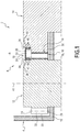
- the variant of the Figure 5 differs from that of the Figure 4 in that the channeling member 32 is configured to cooperate in a sealed manner with the sealing surfaces 34 and 36 of each toothed wheel 12, 14 which are perpendicular to the axis of rotation A1, A2 of these toothed wheels 12, 14.
- each lateral edge of the channeling member 32 is configured to cooperate in sealed manner with the sealing surface 34, 36 of a respective toothed wheel 12, 14.
- Each side edge is provided for this purpose with a scraper 46 configured to scrape the corresponding sealing surface 34, 36.
- the first lateral faces 24, 26 of the teeth 16, 18 are turned towards a region of the internal volume 8 of the casing 4 which is free or in which other mechanical members are located.
- the channeling member 32 is arranged so as to prevent the jets from being projected into this space.
- the mechanism 2 further comprises another channeling member similar to the channeling member 32 and arranged on the side of the second lateral faces 28, 30 of the teeth 16, 18 for channeling lubricant expelled from the spaces 22 in the area of meshing 19.
- the channeling member 32 is separate from the casing 4 and is mounted inside the casing 4, by any suitable means, for example by gluing, welding, screwing and / or riveting.
- the gear 6 has parallel axes.
- the gear 6 has non-parallel axes, in particular with concurrent axes.
- the invention applies to any mechanical system comprising a gear.
- the mechanism 2 may for example be a reduction gear or a manual or automatic gearbox.
Landscapes
- Engineering & Computer Science (AREA)
- General Engineering & Computer Science (AREA)
- Mechanical Engineering (AREA)
- General Details Of Gearings (AREA)
Description
- La présente invention concerne le domaine des mécanismes à lubrification par barbotage, comprenant un engrenage de transmission possédant deux roues dentées engrenant l'une avec l'autre pour l'entraînement d'une roue dentée (roue « menée ») par l'autre (roue « menante »).
- Pour limiter l'usure d'un engrenage, il est nécessaire de lubrifier l'engrenage. Il est en particulier possible de plonger l'engrenage au moins partiellement dans un bain de lubrifiant. On parle alors de lubrification par barbotage.
- On connait des mécanismes à lubrification par barbotage tels que décrit dans
JP H04 366234 A JP H11 350531 A US 4 693 133 A ,JP S50 8375 U JP 2008 128327 JP 2009 191886 A JP H07 54973 A - Un des buts de l'invention est d'améliorer la lubrification par barbotage dans un mécanisme comprenant un engrenage de transmission.
- A cet effet, l'invention propose un mécanisme à lubrification par barbotage, comprenant un carter et un engrenage de transmission disposé à l'intérieur du carter, l'engrenage possédant deux roues dentées munies de dentures respectives engrenant dans une zone d'engrènement, chaque denture possédant une première face latérale et une deuxième face latérales opposées, le mécanisme comprenant en outre un organe de canalisation distinct du carter, fixe par rapport au carter, délimitant un canal et disposé en regard des premières faces latérales au droit de la zone d'engrènement pour canaliser du lubrifiant expulsé de la zone d'engrènement à partir des premières faces latérales circonférentiellement dans la zone d'engrènement.
- Le mécanisme à lubrification par barbotage comprend en option une ou plusieurs des caractéristiques suivantes, prises isolément ou selon toutes les combinaisons techniquement possibles :
- l'organe de canalisation coopère de manière étanche avec une surface d'étanchéité prévue sur au moins une roue dentée ;
- l'organe de canalisation coopère de manière étanche avec une surface d'étanchéité de chaque roue dentée ;
- au moins une roue dentée possède une surface d'étanchéité perpendiculaire à l'axe de rotation de cette roue dentée ;
- au moins une roue dentée possède une surface d'étanchéité de révolution autour de l'axe de rotation de la roue dentée et présentant une étendue suivant cet axe de rotation ;
- au moins une roue dentée possède une surface d'étanchéité cylindrique centrée sur l'axe de rotation de cette roue dentée ;
- l'organe de canalisation est configuré pour racler une surface d'étanchéité d'une roue dentée ;
- l'organe de canalisation coopère de manière étanche avec une surface d'étanchéité d'au moins une roue dentée par l'intermédiaire d'un système d'étanchéité à chicane ; et
- il comprend un déflecteur disposé dans l'espace délimité entre les dentures des deux roues dentées immédiatement en aval de la zone d'engrènement en considérant le sens de rotation des roues dentées autour de leurs axes de rotation, le déflecteur s'étendant sur toute la largeur des dents des roues dentées de l'engrenage et étant configuré pour dévier du lubrifiant circulant circonférentiellement autour d'une roue dentée à l'écart de celle-ci et/ou pour diriger ce lubrifiant circonférentiellement autour de l'autre roue dentée.
- L'invention et ses avantages seront mieux compris à la lecture de la description qui va suivre, donnée uniquement à titre d'exemple non limitatif, et faite en référence aux dessins annexés, sur lesquels :
- La
Figure 1 est une vue en coupe d'un mécanisme comprenant un engrenage de transmission possédant deux roues dentées engrenant l'une avec l'autre ; - La
Figure 2 est vue de dessus de l'engrenage de transmission ; - La
Figure 3 est une vue en coupe selon III-III sur laFigure 2 , illustrant un organe de canalisation du mécanisme ; - Les
Figures 4 et5 sont des vues analogues à celle de laFigure 1 illustrant des variantes. - Le mécanisme 2 à lubrification par barbotage illustré sur les
Figures 1 et2 comprend un carter 4 destiné à recevoir un lubrifiant et un engrenage 6 de transmission disposé à l'intérieur du carter 4. - Le carter 4 délimite un volume interne 8. Le volume interne 8 est destiné à recevoir des organes mécaniques de transmission incluant l'engrenage 6. En particulier le volume interne 8 est prévu pour contenir d'autres organes mécaniques de transmission en plus de l'engrenage 6.
- Le carter 4 est représenté partiellement, seule une paroi de carter 10 étant visible sur la
Figure 1 . La paroi de carter 10 est par exemple une paroi inférieure du carter 10. - Le carter 4 est étanche configuré pour contenir un lubrifiant pour la lubrification des organes mécaniques du mécanisme reçus dans le carter 4, et en particulier de l'engrenage 6.
- L'engrenage 6 comprend des roues dentées 12, 14, chaque roue dentée 12, 14 possédant une denture 16, 18 s'étendant sur la circonférence de la roue dentée 12, 14, les dentures 16, 18 respectives des roues dentées 12, 14 engrenant l'une avec l'autre dans une zone d'engrènement 19. Chaque denture 16, 18 est formée d'une alternance de dents 20 et d'espaces 22 entre les dents 20 sur la circonférence de la roue dentée 12, 14.
- La denture 16, 18 de chaque roue dentée 12, 14 possède une première face latérale 24, 26 et une deuxième face latérale 28, 30 opposées. Chaque dent 20 d'une denture 16, 18 s'étend entre la première face latérale 24, 26 et la deuxième face latérale 28, 30 de la denture 16, 18. Chaque espace 22 d'une denture 16, 18 débouche à une extrémité sur la première face latérale 24, 26 de cette denture 16, 18 et à l'autre extrémité sur la deuxième face latérale 28, 30 de cette denture 16, 18.
- Les premières faces latérales 24, 26 des dentures 16, 18 sont orientées du même côté dans la zone d'engrènement 19 et les deuxièmes faces latérales 28, 30 des dentures 16, 18 sont orientées du même côté dans la zone d'engrènement 19.
- Dans la zone d'engrènement 19, les dentures 16, 18 sont en prise l'une avec l'autre. Dans la zone d'engrènement 19, les dents 20 de chaque denture 16, 18 sont insérées dans les espaces 22 de l'autre denture 16, 18.
- L'engrenage 6 est configuré pour la transmission d'un couple entre les roues dentées 12, 14. En particulier, l'engrenage 6 est configuré pour la transmission d'un couple d'une roue dentée dite « menante » à une roue dentée dite « menée ».
- Les roues dentées 12, 14 sont montées rotatives autour d'axes de rotation A1, A2 respectifs. Les axes de rotation A1, A2 des deux roues dentées 12, 14 sont distincts. L'engrenage est ici à axes parallèles. Les axes de rotation A1, A2 des roues dentées 12, 14 sont parallèles entre eux. La première face latérale 24, 26 et la deuxième face latérale 28, 30 de chaque denture 16, 18 sont ici perpendiculaires à l'axe de rotation A1, A2 de la roue dentée portant cette denture.
- Les roues dentées 12, 14 sont ici montées rotatives sur la paroi de carter 10. La paroi de carter 10 est par exemple une paroi de fond sensiblement horizontale, les axes de rotation A1, A2 étant sensiblement verticaux.
- Dans l'exemple illustré, les dents 20 de chaque denture 16, 18 sont droites. Elles s'étendent entre la première face latérale 24, 26 et la deuxième face latérale 28, 30 sensiblement parallèlement à l'axe de rotation A1, A2 de la roue dentée 12, 14. Chaque espace 22 de la denture 16, 18 débouche sur la première face latérale 24, 26 et la deuxième face latérale 28, 30 axialement relativement à l'axe de rotation A1, A2 de la roue dentée 12, 14. En variante, les dents 20 sont par exemple en hélice ou en chevron. Chaque espace 22 débouche sur la première face latérale 24, 26 et la deuxième face latérale 28, 30 obliquement relativement à l'axe de rotation A1, A2 de la roue dentée 12, 14.
- En fonctionnement, du lubrifiant est présent dans le carter 4. Du lubrifiant est en particulier présent dans les espaces 22 des dentures 16, 18. L'insertion d'une dent 20 d'une denture 16, 18 dans un espace 22 de l'autre denture 16, 18 dans la zone d'engrènement 19 chasse le lubrifiant de cet espace 22 vers les extrémités de l'espace 22, qui débouchent sur les première et deuxième faces latérales 24, 26 ; 28, 30 de la denture 16, 18.
- Ainsi, lorsque les roues dentées 12, 14 tournent, dans la zone d'engrènement 19, des jets de lubrifiant sont expulsés des espaces 22 des dentures 16, 18 à partir des premières et deuxièmes faces 24, 26 ; 28, 30 des dentures 16, 18. Dans le cas présent, les roues dentées 12, 14 sont à axes parallèles et à dents 20 droites, de sorte que les jets de lubrifiant sont sensiblement axiaux.
- Ce phénomène est susceptible de perturber l'écoulement du lubrifiant autour de la zone d'engrènement 19 et de provoquer une accumulation de lubrifiant en amont de la zone d'engrènement 19 en considérant le sens de rotation des roues dentées (Flèches R sur la
Figure 2 ). En outre, les jets de lubrifiant sont susceptibles de perturber le fonctionnement d'autres organes mécaniques de transmission du mécanisme logés dans le carter 4. - Pour pallier ces inconvénients, le mécanisme 2 comprend en outre un organe de canalisation 32 disposé en regard des premières faces latérales 24, 26 des dentures 16, 18 et à cheval sur la zone d'engrènement 19 pour collecter et canaliser du lubrifiant expulsé de la zone d'engrènement 19 à partir desdites premières faces latérales 24, 26.
- L'organe de canalisation 32 est configuré pour forcer le lubrifiant collecté à circuler circonférentiellement par rapport à au moins une des roues dentées 12, 14, dans la zone d'engrènement 19. L'organe de canalisation 32 est ici configuré pour forcer le lubrifiant à circuler circonférentiellement par rapport à la roue dentée 14.
- L'organe de canalisation 32 reste en permanence en regard de la zone d'engrènement 19. L'organe de canalisation 32 est immobile par rapport aux axes de rotation A1, A2 des roues dentées 12, 14. L'organe de canalisation 32 est immobile par rapport au carter 4.
- Dans l'exemple illustré, l'organe de canalisation 32 s'étend circonférentiellement par rapport à une roue dentée, ici la roue dentée 14. L'organe de canalisation 32 s'étend tangentiellement à l'autre roue dentée, ici la roue dentée 12.
- L'organe de canalisation 32 comprend, sur une face tournée vers la zone d'engrènement 19, un canal 33 pour canaliser le lubrifiant expulsé de la zone d'engrènement 19 à partir desdites premières faces latérales 24, 26.
- Le canal 33 est configuré pour collecter les jets de lubrifiant expulsés des premières faces latérales 24, 26 et pour canaliser ces jets de lubrifiant circonférentiellement autour d'au moins une des roues dentées 12, 14, ici la roue dentée 14.
- Le canal 33 s'étend suivant une ligne longitudinale L. La ligne longitudinale L s'étend ici circonférentiellement par rapport à la roue dentée 14.
- L'organe de canalisation 32 s'étend circonférentiellement selon une étendue angulaire limitée autour de l'axe de rotation de l'une des roues dentées 12, 14, i.e. sur une fraction de la circonférence de ladite roue dentée parmi les roues dentées 12, 14. Avantageusement, l'étendue angulaire est inférieure à 90°. L'organe de transmission 32 s'étend ici circonférentiellement selon une étendue angulaire limitée autour de l'axe de rotation de la roue dentée 14, i.e. sur une fraction de la circonférence de la roue dentée 14.
- Le canal 33 possède une première extrémité longitudinale 33A fermée et une deuxième extrémité longitudinale 33B ouverte. La deuxième extrémité longitudinale 33B débouche ici circonférentiellement par rapport à la roue dentée 14.
- Le canal 33 possède une ouverture longitudinale 33C d'étendant le long du canal 33 et tournée vers les faces latérales 24, 26. L'ouverture longitudinale 33C est située sur la face de l'organe de canalisation 32 comprend tournée vers la zone d'engrènement 19
- La première extrémité longitudinale 33A est située de manière que les jets de lubrifiants pénètrent dans le canal 33 à sa première extrémité longitudinale 33A, par l'ouverture longitudinale 33C.
- La première extrémité longitudinale 33A est située au droit de la zone d'engrènement 19, où commencent à se former les jets de lubrifiant.
- Le canal 33 comprend à sa première extrémité longitudinale 33A une surface de déflexion 33D configurée pour dévier les jets de lubrifiant suivant la ligne longitudinale L du canal 33. La surface de déflexion 33D est par exemple inclinée et/ou arrondie. Elle est ici arrondie.
- L'organe de canalisation 32 est configuré pour coopérer étroitement avec des surfaces 34, 36 des roues dentées 12, 14 pour limiter le passage de lubrifiant entre l'organe de canalisation 32 et les roues dentées 12, 14.
- Dans un mode de réalisation, la surface d'étanchéité 34, 36 de chaque roue dentée 12, 16 est une surface de révolution autour de l'axe de rotation A1, A2 de cette roue dentée 12, 16, présentant une étendue axiale suivant l'axe de rotation de la roue dentée 12, 16. La surface d'étanchéité 34, 36 de chaque roue dentée 12, 14 s'étend en saillie axialement par rapport à la première face latérale 24, 26 de la denture 16, 18 de cette roue dentée 12, 14.
- La surface d'étanchéité 34, 36 de chaque roue dentée 12, 16 est ici une surface cylindrique centrée sur l'axe de rotation A1, A2 de la roue dentée 12, 16.
- Les surfaces d'étanchéité 34, 36 se font face l'une l'autre au droit de la zone d'engrènement 19, et l'organe de canalisation 32 est inséré dans l'intervalle délimité entre les surfaces d'étanchéité 34, 36 des deux roues dentées 12, 14.
- Dans un mode de réalisation, l'organe de canalisation 32 coopère avec la surface d'étanchéité 34, 36 de chaque roue dentée 12, 14 par l'intermédiaire de systèmes d'étanchéité à chicane 38, 40.
- Dans l'exemple illustré, l'organe de canalisation 32 coopère avec chaque surface d'étanchéité 34, 36 par un système d'étanchéité à chicane 38, 40 comprenant trois chicanes d'étanchéité 42.
- En fonctionnement, dans la zone d'engrènement, du lubrifiant présent dans les espaces 20 des dentures 16, 18 est expulsé sur les premières faces latérales 24, 26 des dentures 16, 18. Ce lubrifiant est collecté par l'organe de canalisation 32 et entraîné circonférentiellement autour des roues dentées 12, 14 du fait de la rotation de ces dernières autour de leurs axes de rotation A1, A2 respectifs. L'organe de canalisation 32 canalise le lubrifiant circonférentiellement du côté des premières faces latérales 24, 26 des dentures 16, 18.
- Plus spécifiquement, comme visible sur la
Figure 3 , les jets de lubrifiant pénètrent dans le canal 33, par l'ouverture longitudinale 33C, à la première extrémité longitudinale 33A du canal 33, sont déviés, circulent le long du canal 33, et débouchent à la deuxième extrémité longitudinale 33B, circonférentiellement. - Par ailleurs, en aval de la zone d'engrènement, la denture 20 de chaque roue dentée 12, 14 tend à entraîner le lubrifiant circonférentiellement autour de cette roue dentée 12, 14. Lorsqu'une roue dentée 12 (à gauche sur la
Figure 2 ) est de plus petit diamètre que l'autre 14 (à droite sur laFigure 2 ), le lubrifiant circule à la même vitesse circonférentielle autour des deux roues dentées 12, 14, mais parcourt une plus petite distance autour de la roue dentée 12 de petit diamètre et une plus grande distance autour de la roue dentée 14 de grand diamètre. Il en résulte un déséquilibre dans la répartition du lubrifiant. - Pour obvier cet inconvénient, comme illustré sur les
Figure 2 et3 , l'organe de canalisation 32 est configuré pour canaliser le lubrifiant circonférentiellement autour de la roue dentée 14 de plus grand diamètre. Le canal 33 s'étend circonférentiellement par rapport à la roue dentée 14 de plus grand diamètre. - En outre, le mécanisme comprend en option un déflecteur 44 disposé dans l'espace délimité entre les dentures 16, 18 des deux roues dentées 12, 14 immédiatement en aval de la zone d'engrènement 19, le déflecteur 44 étant configuré pour dévier du lubrifiant circulant circonférentiellement autour de la roue dentée 12 de petit diamètre à l'écart de celle-ci et/ou pour diriger ce lubrifiant circonférentiellement autour de la roue dentée 14 de grand diamètre.
- Le déflecteur 44 s'étend ici à partir de la circonférence de la roue dentée 12 de petit diamètre et sensiblement circonférentiellement par rapport à la roue dentée 14 de grand diamètre. Ce déflecteur 44 permet de dévier du lubrifiant circulant circonférentiellement autour de la roue dentée 12 de petit diamètre à l'écart de celle-ci et de diriger ce lubrifiant circonférentiellement autour de la roue dentée 14 de grand diamètre.
- De préférence, le déflecteur 44 s'étend sensiblement sur toute la largeur de la denture 16 de la roue dentée 12 de petit diamètre. La largeur de la denture 16 est la distance entre la première face latérale 24 et la deuxième face latérale 28 de la denture 16.
- Dans l'exemple illustré, comme visible sur la
Figure 3 , le déflecteur 44 est ici venu de matière avec l'organe de canalisation 32. - La variante de la
Figure 4 diffère de celle desFigures 1 à 3 en ce que l'organe de canalisation 32 est configuré pour coopérer de manière étanche avec une surface d'étanchéité 34 d'une roue dentée 12 qui est perpendiculaire à l'axe de rotation A1 de cette roue dentée 12. En particulier, l'organe de canalisation 32 comprend un bord latéral muni d'un racleur 46 configuré pour racler la surface d'étanchéité 34 en question. - Sur la
Figure 4 , la roue dentée 12 de petit diamètre est munie d'une surface d'étanchéité 34 perpendiculaire à l'axe de rotation A1 de cette roue dentée, et la roue dentée 14 de grand diamètre est munie d'une surface d'étanchéité 36 de révolution autour de l'axe de rotation A2 de la roue dentée 14 de grand diamètre. En variante, la configuration est inversée. - La variante de la
Figure 5 diffère de celle de laFigure 4 en ce que l'organe de canalisation 32 est configuré pour coopérer de manière étanche avec les surfaces d'étanchéité 34 et 36 de chaque roue dentée 12, 14 qui sont perpendiculaires à l'axe de rotation A1, A2 de ces roues dentées 12, 14. En particulier, chaque bord latéral de l'organe de canalisation 32 est configuré pour coopérer de manière étanche avec la surface d'étanchéité 34 ,36 d'une roue dentée 12, 14 respective. Chaque bord latéral est muni à cet effet d'un racleur 46 configuré pour racler la surface d'étanchéité 34, 36 correspondante. - Sur les
Figures 1 ,4 et5 , les premières faces latérales 24, 26 des dentures 16, 18 sont tournées vers une région du volume interne 8 du carter 4 qui est libre ou dans laquelle se situent d'autres organes mécaniques. L'organe de canalisation 32 est disposé de façon à empêcher les jets d'être projetés dans cette espace. - Les deuxièmes faces latérales 28, 30 des dentures 16, 18 sont tournées vers la paroi de carter 10, de sorte que des jets de lubrifiant expulsés des espaces 22 des dentures sur les deuxièmes faces latérales 28, 30 sont bloqués par cette paroi de carter 10. En variante, le mécanisme 2 comprend en outre un autre organe de canalisation similaire à l'organe de canalisation 32 et disposé du côté des deuxièmes faces latérales 28, 30 des dentures 16, 18 pour canaliser du lubrifiant expulsé des espaces 22 dans la zone d'engrènement 19.
- L'organe de canalisation 32 est distinct du carter 4 et est monté à l'intérieur du carter 4, par tout moyen approprié, par exemple par collage, soudage, vissage et/ou rivetage.
- Dans l'exemple illustré, l'engrenage 6 est à axes parallèles. Dans une variante, l'engrenage 6 est à axes non parallèles, en particulier à axes concourants.
- L'invention s'applique à tout système mécanique comprenant un engrenage. En particulier, le mécanisme 2 peut être par exemple un réducteur ou une boîte de vitesse manuelle ou automatique.
Claims (11)
- Mécanisme à lubrification par barbotage, comprenant un carter (4) et un engrenage (6) de transmission disposé à l'intérieur du carter (4), l'engrenage (6) possédant deux roues dentées (12, 14) munies de dentures (16, 18) respectives engrenant dans une zone d'engrènement (19), chaque denture (16, 18) possédant une première face latérale (24, 26) et une deuxième face latérales (28, 30) opposées, le mécanisme comprenant en outre un organe de canalisation (32) distinct du carter (4), fixe par rapport au carter (4), délimitant un canal (33) et disposé en regard des premières faces latérales (24, 26) au droit de la zone d'engrènement (19) pour canaliser du lubrifiant expulsé de la zone d'engrènement (19) à partir des premières faces latérales (24, 26) circonférentiellement dans la zone d'engrènement (19).
- Mécanisme selon la revendication 1, dans lequel l'organe de canalisation (32) coopère de manière étanche avec une surface d'étanchéité prévue sur au moins une roue dentée (12, 14).
- Mécanisme selon la revendication 2, dans lequel l'organe de canalisation (32) coopère de manière étanche avec une surface d'étanchéité de chaque roue dentée (12, 14).
- Mécanisme selon la revendication 2 ou 3, dans lequel au moins une roue dentée (12, 14) possède une surface d'étanchéité perpendiculaire à l'axe de rotation de cette roue dentée (12, 14).
- Mécanisme selon l'une quelconque des revendications 2 à 4, dans lequel au moins une roue dentée (12, 14) possède une surface d'étanchéité de révolution autour de l'axe de rotation de la roue dentée (12, 14) et présentant une étendue suivant cet axe de rotation.
- Mécanisme selon l'une quelconque des revendications 2 à 5, dans lequel au moins une roue dentée (12, 14) possède une surface d'étanchéité cylindrique centrée sur l'axe de rotation de cette roue dentée (12, 14).
- Mécanisme selon l'une quelconque des revendications 2 à 6, dans lequel l'organe de canalisation (32) est configuré pour racler une surface d'étanchéité d'une roue dentée (12, 14).
- Mécanisme selon l'une quelconque des revendications 2 à 7, dans lequel l'organe de canalisation (32) coopère de manière étanche avec une surface d'étanchéité d'au moins une roue dentée par l'intermédiaire d'un système d'étanchéité à chicane.
- Mécanisme selon l'une quelconque des revendications précédentes, comprenant un déflecteur (44) disposé dans l'espace délimité entre les dentures (16, 18) des deux roues dentées (12, 14) immédiatement en aval de la zone d'engrènement (19) en considérant le sens de rotation des roues dentées (12, 14) autour de leurs axes de rotation (A1, A2), le déflecteur (44) s'étendant sur toute la largeur des dents des roues dentées (12, 14) de l'engrenage (6) et étant configuré pour dévier du lubrifiant circulant circonférentiellement autour d'une roue dentée (12) à l'écart de celle-ci et/ou pour diriger ce lubrifiant circonférentiellement autour de l'autre roue dentée (14).
- Mécanisme selon l'une quelconque des revendications précédentes, dans lequel l'organe de canalisation (32) s'étend circonférentiellement par rapport à la roue de plus grand diamètre (14).
- Mécanisme selon l'une quelconque des revendications précédentes, dans lequel l'organe de canalisation (32) possède une première extrémité longitudinale fermée (33A) et une deuxième extrémité longitudinale ouverte (33B).
Applications Claiming Priority (1)
| Application Number | Priority Date | Filing Date | Title |
|---|---|---|---|
| FR1601315A FR3055687B1 (fr) | 2016-09-07 | 2016-09-07 | Mecanisme a lubrification par barbotage comprenant un engrenage de transmission |
Publications (2)
| Publication Number | Publication Date |
|---|---|
| EP3293437A1 EP3293437A1 (fr) | 2018-03-14 |
| EP3293437B1 true EP3293437B1 (fr) | 2020-05-13 |
Family
ID=58314274
Family Applications (1)
| Application Number | Title | Priority Date | Filing Date |
|---|---|---|---|
| EP17189694.7A Active EP3293437B1 (fr) | 2016-09-07 | 2017-09-06 | Mécanisme à lubrification par barbotage comprenant un engrenage de transmission |
Country Status (4)
| Country | Link |
|---|---|
| EP (1) | EP3293437B1 (fr) |
| ES (1) | ES2795898T3 (fr) |
| FR (1) | FR3055687B1 (fr) |
| SG (1) | SG10201707297SA (fr) |
Families Citing this family (1)
| Publication number | Priority date | Publication date | Assignee | Title |
|---|---|---|---|---|
| WO2023119982A1 (fr) * | 2021-12-24 | 2023-06-29 | ナブテスコ株式会社 | Mécanisme d'inhibition de fuite de lubrifiant et mécanisme d'engrenage |
Family Cites Families (7)
| Publication number | Priority date | Publication date | Assignee | Title |
|---|---|---|---|---|
| JPS508375U (fr) * | 1973-05-09 | 1975-01-28 | ||
| US4693133A (en) * | 1982-06-18 | 1987-09-15 | Honda Giken Kogyo Kabushiki Kaisha | Noise reduction in gear transmission |
| JPH04366234A (ja) * | 1991-06-14 | 1992-12-18 | Hitachi Constr Mach Co Ltd | 建設機械用旋回装置 |
| JPH0754973A (ja) * | 1993-08-09 | 1995-02-28 | Hitachi Constr Mach Co Ltd | 動力伝達装置 |
| JPH11350531A (ja) * | 1998-06-05 | 1999-12-21 | Hitachi Constr Mach Co Ltd | 建設機械の旋回装置 |
| JP4805791B2 (ja) * | 2006-11-20 | 2011-11-02 | 株式会社東芝 | 鉄道車両用駆動装置 |
| JP5155684B2 (ja) * | 2008-02-13 | 2013-03-06 | 株式会社小松製作所 | ギヤケース |
-
2016
- 2016-09-07 FR FR1601315A patent/FR3055687B1/fr not_active Expired - Fee Related
-
2017
- 2017-09-06 ES ES17189694T patent/ES2795898T3/es active Active
- 2017-09-06 EP EP17189694.7A patent/EP3293437B1/fr active Active
- 2017-09-07 SG SG10201707297SA patent/SG10201707297SA/en unknown
Non-Patent Citations (1)
| Title |
|---|
| None * |
Also Published As
| Publication number | Publication date |
|---|---|
| FR3055687B1 (fr) | 2019-05-10 |
| EP3293437A1 (fr) | 2018-03-14 |
| ES2795898T3 (es) | 2020-11-25 |
| FR3055687A1 (fr) | 2018-03-09 |
| SG10201707297SA (en) | 2018-04-27 |
Similar Documents
| Publication | Publication Date | Title |
|---|---|---|
| CA2946958C (fr) | Module de turbomachine comportant un carter autour d'un equipement avec un capot de recuperation d'huile de lubrification | |
| EP3350483B1 (fr) | Réducteur à engrenage avec graisseur intégré pour direction assistée | |
| EP3516268B1 (fr) | Deflecteur de guidage de lubrifiant pour l'alimentation d'un arbre creux de boite de vitesses | |
| CH671553A5 (fr) | ||
| FR2906329A1 (fr) | Structure de dispositif de transmission de couple de demarrage de moteur equipe d'un embrayage a galets | |
| EP4172008B1 (fr) | Dispositif d'essuyage pour système de détection | |
| FR3084407A1 (fr) | Gouttiere de canalisation d'huile de lubrification d'une turbomachine d'aeronef | |
| FR3091737A1 (fr) | Structure de lubrification d'un dispositif d'entrainement de véhicule hybride | |
| EP1832766A2 (fr) | Procédé de lubrication d'un dispositif de transmission de couple | |
| WO2014044958A1 (fr) | Boîtier de transmission et engin équipé d'un tel boîtier de transmission | |
| EP3293437A1 (fr) | Mécanisme à lubrification par barbotage comprenant un engrenage de transmission | |
| FR2534654A1 (fr) | Dispositif d'etancheite comportant au moins une levre coulissante | |
| FR3027972A1 (fr) | Compresseur, notamment pour vehicule automobile | |
| EP2647769B1 (fr) | Dispositif de fraisage adaptable sur machine de travaux publics | |
| FR2874243A1 (fr) | Entrainement par engreanges | |
| FR3025580A3 (fr) | "boite de vitesses comportant un deflecteur de lubrifiant fixe a une bague exterieure d'un palier de roulement" | |
| FR2782767A1 (fr) | Differentiel a blocage,sensible au couple et comportant peu de pieces | |
| EP2282082A1 (fr) | Dispositif de transmission de couple comprenant un racleur d'huile | |
| EP1805434B1 (fr) | Boite de vitesses pour vehicule automobile comprenant un dispositif de lubrification forcee des roues d'engrenage | |
| EP1775499A1 (fr) | Dispositif de lubrification d'au moins un engrenage d'une boîte de vitesses | |
| FR2927395A3 (fr) | Bague de protection d'un joint d'etancheite dynamique entre une piece fixe et un arbre de transmission d'un groupe motopropulseur d'un vehicule automobile et groupe motopropulseur comportant une telle bague de protection | |
| WO2018100007A1 (fr) | Système de refroidissement pour mecanisme d'embrayage | |
| FR2747438A1 (fr) | Ensemble de transmission a mobilite axiale | |
| FR3155043A1 (fr) | Transmission à différentiel pour véhicule automobile avec pompe à huile intégrée | |
| EP3700770B1 (fr) | Prise de force déportée pour machine hydraulique |
Legal Events
| Date | Code | Title | Description |
|---|---|---|---|
| PUAI | Public reference made under article 153(3) epc to a published international application that has entered the european phase |
Free format text: ORIGINAL CODE: 0009012 |
|
| STAA | Information on the status of an ep patent application or granted ep patent |
Free format text: STATUS: THE APPLICATION HAS BEEN PUBLISHED |
|
| AK | Designated contracting states |
Kind code of ref document: A1 Designated state(s): AL AT BE BG CH CY CZ DE DK EE ES FI FR GB GR HR HU IE IS IT LI LT LU LV MC MK MT NL NO PL PT RO RS SE SI SK SM TR |
|
| AX | Request for extension of the european patent |
Extension state: BA ME |
|
| STAA | Information on the status of an ep patent application or granted ep patent |
Free format text: STATUS: REQUEST FOR EXAMINATION WAS MADE |
|
| 17P | Request for examination filed |
Effective date: 20180308 |
|
| RBV | Designated contracting states (corrected) |
Designated state(s): AL AT BE BG CH CY CZ DE DK EE ES FI FR GB GR HR HU IE IS IT LI LT LU LV MC MK MT NL NO PL PT RO RS SE SI SK SM TR |
|
| GRAP | Despatch of communication of intention to grant a patent |
Free format text: ORIGINAL CODE: EPIDOSNIGR1 |
|
| STAA | Information on the status of an ep patent application or granted ep patent |
Free format text: STATUS: GRANT OF PATENT IS INTENDED |
|
| INTG | Intention to grant announced |
Effective date: 20200206 |
|
| GRAS | Grant fee paid |
Free format text: ORIGINAL CODE: EPIDOSNIGR3 |
|
| GRAA | (expected) grant |
Free format text: ORIGINAL CODE: 0009210 |
|
| STAA | Information on the status of an ep patent application or granted ep patent |
Free format text: STATUS: THE PATENT HAS BEEN GRANTED |
|
| AK | Designated contracting states |
Kind code of ref document: B1 Designated state(s): AL AT BE BG CH CY CZ DE DK EE ES FI FR GB GR HR HU IE IS IT LI LT LU LV MC MK MT NL NO PL PT RO RS SE SI SK SM TR |
|
| REG | Reference to a national code |
Ref country code: GB Ref legal event code: FG4D Free format text: NOT ENGLISH |
|
| REG | Reference to a national code |
Ref country code: CH Ref legal event code: EP |
|
| REG | Reference to a national code |
Ref country code: DE Ref legal event code: R096 Ref document number: 602017016373 Country of ref document: DE |
|
| REG | Reference to a national code |
Ref country code: AT Ref legal event code: REF Ref document number: 1270748 Country of ref document: AT Kind code of ref document: T Effective date: 20200615 |
|
| REG | Reference to a national code |
Ref country code: LT Ref legal event code: MG4D |
|
| REG | Reference to a national code |
Ref country code: NL Ref legal event code: MP Effective date: 20200513 |
|
| PG25 | Lapsed in a contracting state [announced via postgrant information from national office to epo] |
Ref country code: IS Free format text: LAPSE BECAUSE OF FAILURE TO SUBMIT A TRANSLATION OF THE DESCRIPTION OR TO PAY THE FEE WITHIN THE PRESCRIBED TIME-LIMIT Effective date: 20200913 Ref country code: FI Free format text: LAPSE BECAUSE OF FAILURE TO SUBMIT A TRANSLATION OF THE DESCRIPTION OR TO PAY THE FEE WITHIN THE PRESCRIBED TIME-LIMIT Effective date: 20200513 Ref country code: PT Free format text: LAPSE BECAUSE OF FAILURE TO SUBMIT A TRANSLATION OF THE DESCRIPTION OR TO PAY THE FEE WITHIN THE PRESCRIBED TIME-LIMIT Effective date: 20200914 Ref country code: LT Free format text: LAPSE BECAUSE OF FAILURE TO SUBMIT A TRANSLATION OF THE DESCRIPTION OR TO PAY THE FEE WITHIN THE PRESCRIBED TIME-LIMIT Effective date: 20200513 Ref country code: NO Free format text: LAPSE BECAUSE OF FAILURE TO SUBMIT A TRANSLATION OF THE DESCRIPTION OR TO PAY THE FEE WITHIN THE PRESCRIBED TIME-LIMIT Effective date: 20200813 Ref country code: SE Free format text: LAPSE BECAUSE OF FAILURE TO SUBMIT A TRANSLATION OF THE DESCRIPTION OR TO PAY THE FEE WITHIN THE PRESCRIBED TIME-LIMIT Effective date: 20200513 Ref country code: GR Free format text: LAPSE BECAUSE OF FAILURE TO SUBMIT A TRANSLATION OF THE DESCRIPTION OR TO PAY THE FEE WITHIN THE PRESCRIBED TIME-LIMIT Effective date: 20200814 |
|
| REG | Reference to a national code |
Ref country code: ES Ref legal event code: FG2A Ref document number: 2795898 Country of ref document: ES Kind code of ref document: T3 Effective date: 20201125 |
|
| PG25 | Lapsed in a contracting state [announced via postgrant information from national office to epo] |
Ref country code: BG Free format text: LAPSE BECAUSE OF FAILURE TO SUBMIT A TRANSLATION OF THE DESCRIPTION OR TO PAY THE FEE WITHIN THE PRESCRIBED TIME-LIMIT Effective date: 20200813 Ref country code: RS Free format text: LAPSE BECAUSE OF FAILURE TO SUBMIT A TRANSLATION OF THE DESCRIPTION OR TO PAY THE FEE WITHIN THE PRESCRIBED TIME-LIMIT Effective date: 20200513 Ref country code: LV Free format text: LAPSE BECAUSE OF FAILURE TO SUBMIT A TRANSLATION OF THE DESCRIPTION OR TO PAY THE FEE WITHIN THE PRESCRIBED TIME-LIMIT Effective date: 20200513 Ref country code: HR Free format text: LAPSE BECAUSE OF FAILURE TO SUBMIT A TRANSLATION OF THE DESCRIPTION OR TO PAY THE FEE WITHIN THE PRESCRIBED TIME-LIMIT Effective date: 20200513 |
|
| REG | Reference to a national code |
Ref country code: AT Ref legal event code: MK05 Ref document number: 1270748 Country of ref document: AT Kind code of ref document: T Effective date: 20200513 |
|
| PG25 | Lapsed in a contracting state [announced via postgrant information from national office to epo] |
Ref country code: AL Free format text: LAPSE BECAUSE OF FAILURE TO SUBMIT A TRANSLATION OF THE DESCRIPTION OR TO PAY THE FEE WITHIN THE PRESCRIBED TIME-LIMIT Effective date: 20200513 Ref country code: NL Free format text: LAPSE BECAUSE OF FAILURE TO SUBMIT A TRANSLATION OF THE DESCRIPTION OR TO PAY THE FEE WITHIN THE PRESCRIBED TIME-LIMIT Effective date: 20200513 |
|
| PG25 | Lapsed in a contracting state [announced via postgrant information from national office to epo] |
Ref country code: DK Free format text: LAPSE BECAUSE OF FAILURE TO SUBMIT A TRANSLATION OF THE DESCRIPTION OR TO PAY THE FEE WITHIN THE PRESCRIBED TIME-LIMIT Effective date: 20200513 Ref country code: AT Free format text: LAPSE BECAUSE OF FAILURE TO SUBMIT A TRANSLATION OF THE DESCRIPTION OR TO PAY THE FEE WITHIN THE PRESCRIBED TIME-LIMIT Effective date: 20200513 Ref country code: EE Free format text: LAPSE BECAUSE OF FAILURE TO SUBMIT A TRANSLATION OF THE DESCRIPTION OR TO PAY THE FEE WITHIN THE PRESCRIBED TIME-LIMIT Effective date: 20200513 Ref country code: SM Free format text: LAPSE BECAUSE OF FAILURE TO SUBMIT A TRANSLATION OF THE DESCRIPTION OR TO PAY THE FEE WITHIN THE PRESCRIBED TIME-LIMIT Effective date: 20200513 Ref country code: RO Free format text: LAPSE BECAUSE OF FAILURE TO SUBMIT A TRANSLATION OF THE DESCRIPTION OR TO PAY THE FEE WITHIN THE PRESCRIBED TIME-LIMIT Effective date: 20200513 |
|
| REG | Reference to a national code |
Ref country code: DE Ref legal event code: R097 Ref document number: 602017016373 Country of ref document: DE |
|
| PG25 | Lapsed in a contracting state [announced via postgrant information from national office to epo] |
Ref country code: PL Free format text: LAPSE BECAUSE OF FAILURE TO SUBMIT A TRANSLATION OF THE DESCRIPTION OR TO PAY THE FEE WITHIN THE PRESCRIBED TIME-LIMIT Effective date: 20200513 Ref country code: SK Free format text: LAPSE BECAUSE OF FAILURE TO SUBMIT A TRANSLATION OF THE DESCRIPTION OR TO PAY THE FEE WITHIN THE PRESCRIBED TIME-LIMIT Effective date: 20200513 |
|
| PLBE | No opposition filed within time limit |
Free format text: ORIGINAL CODE: 0009261 |
|
| STAA | Information on the status of an ep patent application or granted ep patent |
Free format text: STATUS: NO OPPOSITION FILED WITHIN TIME LIMIT |
|
| 26N | No opposition filed |
Effective date: 20210216 |
|
| REG | Reference to a national code |
Ref country code: CH Ref legal event code: PL |
|
| PG25 | Lapsed in a contracting state [announced via postgrant information from national office to epo] |
Ref country code: SI Free format text: LAPSE BECAUSE OF FAILURE TO SUBMIT A TRANSLATION OF THE DESCRIPTION OR TO PAY THE FEE WITHIN THE PRESCRIBED TIME-LIMIT Effective date: 20200513 |
|
| REG | Reference to a national code |
Ref country code: BE Ref legal event code: MM Effective date: 20200930 |
|
| PG25 | Lapsed in a contracting state [announced via postgrant information from national office to epo] |
Ref country code: LU Free format text: LAPSE BECAUSE OF NON-PAYMENT OF DUE FEES Effective date: 20200906 |
|
| PG25 | Lapsed in a contracting state [announced via postgrant information from national office to epo] |
Ref country code: CH Free format text: LAPSE BECAUSE OF NON-PAYMENT OF DUE FEES Effective date: 20200930 Ref country code: BE Free format text: LAPSE BECAUSE OF NON-PAYMENT OF DUE FEES Effective date: 20200930 Ref country code: IE Free format text: LAPSE BECAUSE OF NON-PAYMENT OF DUE FEES Effective date: 20200906 Ref country code: LI Free format text: LAPSE BECAUSE OF NON-PAYMENT OF DUE FEES Effective date: 20200930 |
|
| PG25 | Lapsed in a contracting state [announced via postgrant information from national office to epo] |
Ref country code: TR Free format text: LAPSE BECAUSE OF FAILURE TO SUBMIT A TRANSLATION OF THE DESCRIPTION OR TO PAY THE FEE WITHIN THE PRESCRIBED TIME-LIMIT Effective date: 20200513 Ref country code: MT Free format text: LAPSE BECAUSE OF FAILURE TO SUBMIT A TRANSLATION OF THE DESCRIPTION OR TO PAY THE FEE WITHIN THE PRESCRIBED TIME-LIMIT Effective date: 20200513 Ref country code: CY Free format text: LAPSE BECAUSE OF FAILURE TO SUBMIT A TRANSLATION OF THE DESCRIPTION OR TO PAY THE FEE WITHIN THE PRESCRIBED TIME-LIMIT Effective date: 20200513 |
|
| PG25 | Lapsed in a contracting state [announced via postgrant information from national office to epo] |
Ref country code: MK Free format text: LAPSE BECAUSE OF FAILURE TO SUBMIT A TRANSLATION OF THE DESCRIPTION OR TO PAY THE FEE WITHIN THE PRESCRIBED TIME-LIMIT Effective date: 20200513 Ref country code: MC Free format text: LAPSE BECAUSE OF FAILURE TO SUBMIT A TRANSLATION OF THE DESCRIPTION OR TO PAY THE FEE WITHIN THE PRESCRIBED TIME-LIMIT Effective date: 20200513 |
|
| P01 | Opt-out of the competence of the unified patent court (upc) registered |
Effective date: 20230425 |
|
| PGFP | Annual fee paid to national office [announced via postgrant information from national office to epo] |
Ref country code: DE Payment date: 20250916 Year of fee payment: 9 |
|
| PGFP | Annual fee paid to national office [announced via postgrant information from national office to epo] |
Ref country code: IT Payment date: 20250909 Year of fee payment: 9 |
|
| PGFP | Annual fee paid to national office [announced via postgrant information from national office to epo] |
Ref country code: GB Payment date: 20250919 Year of fee payment: 9 |
|
| PGFP | Annual fee paid to national office [announced via postgrant information from national office to epo] |
Ref country code: FR Payment date: 20250929 Year of fee payment: 9 |
|
| PGFP | Annual fee paid to national office [announced via postgrant information from national office to epo] |
Ref country code: CZ Payment date: 20250904 Year of fee payment: 9 |
|
| PGFP | Annual fee paid to national office [announced via postgrant information from national office to epo] |
Ref country code: ES Payment date: 20251015 Year of fee payment: 9 |