EP3293379A1 - Combined heat exchanger and exhaust silencer - Google Patents
Combined heat exchanger and exhaust silencer Download PDFInfo
- Publication number
- EP3293379A1 EP3293379A1 EP16188360.8A EP16188360A EP3293379A1 EP 3293379 A1 EP3293379 A1 EP 3293379A1 EP 16188360 A EP16188360 A EP 16188360A EP 3293379 A1 EP3293379 A1 EP 3293379A1
- Authority
- EP
- European Patent Office
- Prior art keywords
- pipe
- heat exchanger
- housing
- bypass
- end portion
- Prior art date
- Legal status (The legal status is an assumption and is not a legal conclusion. Google has not performed a legal analysis and makes no representation as to the accuracy of the status listed.)
- Granted
Links
Images



Classifications
-
- F—MECHANICAL ENGINEERING; LIGHTING; HEATING; WEAPONS; BLASTING
- F01—MACHINES OR ENGINES IN GENERAL; ENGINE PLANTS IN GENERAL; STEAM ENGINES
- F01N—GAS-FLOW SILENCERS OR EXHAUST APPARATUS FOR MACHINES OR ENGINES IN GENERAL; GAS-FLOW SILENCERS OR EXHAUST APPARATUS FOR INTERNAL-COMBUSTION ENGINES
- F01N3/00—Exhaust or silencing apparatus having means for purifying, rendering innocuous, or otherwise treating exhaust
- F01N3/02—Exhaust or silencing apparatus having means for purifying, rendering innocuous, or otherwise treating exhaust for cooling, or for removing solid constituents of, exhaust
- F01N3/04—Exhaust or silencing apparatus having means for purifying, rendering innocuous, or otherwise treating exhaust for cooling, or for removing solid constituents of, exhaust using liquids
- F01N3/043—Exhaust or silencing apparatus having means for purifying, rendering innocuous, or otherwise treating exhaust for cooling, or for removing solid constituents of, exhaust using liquids without contact between liquid and exhaust gases
-
- F—MECHANICAL ENGINEERING; LIGHTING; HEATING; WEAPONS; BLASTING
- F01—MACHINES OR ENGINES IN GENERAL; ENGINE PLANTS IN GENERAL; STEAM ENGINES
- F01N—GAS-FLOW SILENCERS OR EXHAUST APPARATUS FOR MACHINES OR ENGINES IN GENERAL; GAS-FLOW SILENCERS OR EXHAUST APPARATUS FOR INTERNAL-COMBUSTION ENGINES
- F01N5/00—Exhaust or silencing apparatus combined or associated with devices profiting by exhaust energy
- F01N5/02—Exhaust or silencing apparatus combined or associated with devices profiting by exhaust energy the devices using heat
-
- F—MECHANICAL ENGINEERING; LIGHTING; HEATING; WEAPONS; BLASTING
- F01—MACHINES OR ENGINES IN GENERAL; ENGINE PLANTS IN GENERAL; STEAM ENGINES
- F01N—GAS-FLOW SILENCERS OR EXHAUST APPARATUS FOR MACHINES OR ENGINES IN GENERAL; GAS-FLOW SILENCERS OR EXHAUST APPARATUS FOR INTERNAL-COMBUSTION ENGINES
- F01N1/00—Silencing apparatus characterised by method of silencing
- F01N1/24—Silencing apparatus characterised by method of silencing by using sound-absorbing materials
-
- F—MECHANICAL ENGINEERING; LIGHTING; HEATING; WEAPONS; BLASTING
- F01—MACHINES OR ENGINES IN GENERAL; ENGINE PLANTS IN GENERAL; STEAM ENGINES
- F01N—GAS-FLOW SILENCERS OR EXHAUST APPARATUS FOR MACHINES OR ENGINES IN GENERAL; GAS-FLOW SILENCERS OR EXHAUST APPARATUS FOR INTERNAL-COMBUSTION ENGINES
- F01N13/00—Exhaust or silencing apparatus characterised by constructional features
- F01N13/08—Other arrangements or adaptations of exhaust conduits
-
- F—MECHANICAL ENGINEERING; LIGHTING; HEATING; WEAPONS; BLASTING
- F01—MACHINES OR ENGINES IN GENERAL; ENGINE PLANTS IN GENERAL; STEAM ENGINES
- F01N—GAS-FLOW SILENCERS OR EXHAUST APPARATUS FOR MACHINES OR ENGINES IN GENERAL; GAS-FLOW SILENCERS OR EXHAUST APPARATUS FOR INTERNAL-COMBUSTION ENGINES
- F01N3/00—Exhaust or silencing apparatus having means for purifying, rendering innocuous, or otherwise treating exhaust
- F01N3/02—Exhaust or silencing apparatus having means for purifying, rendering innocuous, or otherwise treating exhaust for cooling, or for removing solid constituents of, exhaust
- F01N3/0205—Exhaust or silencing apparatus having means for purifying, rendering innocuous, or otherwise treating exhaust for cooling, or for removing solid constituents of, exhaust using heat exchangers
-
- F—MECHANICAL ENGINEERING; LIGHTING; HEATING; WEAPONS; BLASTING
- F01—MACHINES OR ENGINES IN GENERAL; ENGINE PLANTS IN GENERAL; STEAM ENGINES
- F01N—GAS-FLOW SILENCERS OR EXHAUST APPARATUS FOR MACHINES OR ENGINES IN GENERAL; GAS-FLOW SILENCERS OR EXHAUST APPARATUS FOR INTERNAL-COMBUSTION ENGINES
- F01N2230/00—Combination of silencers and other devices
-
- F—MECHANICAL ENGINEERING; LIGHTING; HEATING; WEAPONS; BLASTING
- F01—MACHINES OR ENGINES IN GENERAL; ENGINE PLANTS IN GENERAL; STEAM ENGINES
- F01N—GAS-FLOW SILENCERS OR EXHAUST APPARATUS FOR MACHINES OR ENGINES IN GENERAL; GAS-FLOW SILENCERS OR EXHAUST APPARATUS FOR INTERNAL-COMBUSTION ENGINES
- F01N2240/00—Combination or association of two or more different exhaust treating devices, or of at least one such device with an auxiliary device, not covered by indexing codes F01N2230/00 or F01N2250/00, one of the devices being
- F01N2240/02—Combination or association of two or more different exhaust treating devices, or of at least one such device with an auxiliary device, not covered by indexing codes F01N2230/00 or F01N2250/00, one of the devices being a heat exchanger
-
- F—MECHANICAL ENGINEERING; LIGHTING; HEATING; WEAPONS; BLASTING
- F01—MACHINES OR ENGINES IN GENERAL; ENGINE PLANTS IN GENERAL; STEAM ENGINES
- F01N—GAS-FLOW SILENCERS OR EXHAUST APPARATUS FOR MACHINES OR ENGINES IN GENERAL; GAS-FLOW SILENCERS OR EXHAUST APPARATUS FOR INTERNAL-COMBUSTION ENGINES
- F01N2240/00—Combination or association of two or more different exhaust treating devices, or of at least one such device with an auxiliary device, not covered by indexing codes F01N2230/00 or F01N2250/00, one of the devices being
- F01N2240/36—Combination or association of two or more different exhaust treating devices, or of at least one such device with an auxiliary device, not covered by indexing codes F01N2230/00 or F01N2250/00, one of the devices being an exhaust flap
-
- F—MECHANICAL ENGINEERING; LIGHTING; HEATING; WEAPONS; BLASTING
- F01—MACHINES OR ENGINES IN GENERAL; ENGINE PLANTS IN GENERAL; STEAM ENGINES
- F01N—GAS-FLOW SILENCERS OR EXHAUST APPARATUS FOR MACHINES OR ENGINES IN GENERAL; GAS-FLOW SILENCERS OR EXHAUST APPARATUS FOR INTERNAL-COMBUSTION ENGINES
- F01N2410/00—By-passing, at least partially, exhaust from inlet to outlet of apparatus, to atmosphere or to other device
-
- F—MECHANICAL ENGINEERING; LIGHTING; HEATING; WEAPONS; BLASTING
- F01—MACHINES OR ENGINES IN GENERAL; ENGINE PLANTS IN GENERAL; STEAM ENGINES
- F01N—GAS-FLOW SILENCERS OR EXHAUST APPARATUS FOR MACHINES OR ENGINES IN GENERAL; GAS-FLOW SILENCERS OR EXHAUST APPARATUS FOR INTERNAL-COMBUSTION ENGINES
- F01N2470/00—Structure or shape of exhaust gas passages, pipes or tubes
-
- F—MECHANICAL ENGINEERING; LIGHTING; HEATING; WEAPONS; BLASTING
- F01—MACHINES OR ENGINES IN GENERAL; ENGINE PLANTS IN GENERAL; STEAM ENGINES
- F01N—GAS-FLOW SILENCERS OR EXHAUST APPARATUS FOR MACHINES OR ENGINES IN GENERAL; GAS-FLOW SILENCERS OR EXHAUST APPARATUS FOR INTERNAL-COMBUSTION ENGINES
- F01N2470/00—Structure or shape of exhaust gas passages, pipes or tubes
- F01N2470/24—Concentric tubes or tubes being concentric to housing, e.g. telescopically assembled
-
- Y—GENERAL TAGGING OF NEW TECHNOLOGICAL DEVELOPMENTS; GENERAL TAGGING OF CROSS-SECTIONAL TECHNOLOGIES SPANNING OVER SEVERAL SECTIONS OF THE IPC; TECHNICAL SUBJECTS COVERED BY FORMER USPC CROSS-REFERENCE ART COLLECTIONS [XRACs] AND DIGESTS
- Y02—TECHNOLOGIES OR APPLICATIONS FOR MITIGATION OR ADAPTATION AGAINST CLIMATE CHANGE
- Y02T—CLIMATE CHANGE MITIGATION TECHNOLOGIES RELATED TO TRANSPORTATION
- Y02T10/00—Road transport of goods or passengers
- Y02T10/10—Internal combustion engine [ICE] based vehicles
- Y02T10/12—Improving ICE efficiencies
Definitions
- the present invention relates to a combined heat exchanger and exhaust silencer for a vehicle.
- an internal combustion engine of a vehicle is equipped with an exhaust system.
- the exhaust system functions to reduce the noise from the engine while emitting the exhaust out from the engine.
- an exhaust silencer is arranged to define a path for the exhaust gas such that the noise is reduced.
- the exhaust system may also comprise a catalytic converter for converting toxic gases in the exhaust gas to less toxic gases.
- Heat from the exhaust gas may be recovered from the exhaust gas and be used for e.g. heating the cabin of the vehicle, the coolant in the radiator, the engine oil or the transmission oil in a so called heat-to-heat device.
- the recovered heat may also be used to produce electric energy or to provide additional power to the drive line of the vehicle using a heat-to-power device.
- a heat exchanger may be located as part of the exhaust system. In such heat exchanger for an internal combustion engine, heat is transferred from exhaust gas to a working media such as a fluid.
- the heat exchanger can be of various designs, such as tube or plate heat exchangers. However, heat exchangers are bulky, and space conflicts often occur if these heat exchangers are integrated in the exhaust line. Normally, also a bypass is required to switch off the waste heat recovery system at higher engine loads.
- EP2733322 describes a heat exchanger for an exhaust system.
- heat exchanger pipes are arranged along a first path for the exhaust gas and there is also shown a bypass path in which the exhaust gas bypasses the heat exchanger pipes.
- improvements appear to be possible with relation to the heat exchanger efficiency and further also in relation to noise reduction in the bypass path.
- a combined heat exchanger and exhaust silencer for a vehicle, comprising: an inlet and an outlet for an exhaust gas flow; a housing arranged with a first end portion at the inlet and a second end portion at the outlet such that the exhaust gas can flow through the housing; a bypass pipe arranged in the housing, the bypass pipe having a perforated wall portion, the bypass pipe defining a first flow channel for the exhaust gas through the housing; a second pipe arranged in the housing, the second pipe having a perforated wall portion, the second pipe being arranged extend from the first end portion to the second end portion of the housing; a third pipe arranged in the housing, the third pipe having a perforated wall portion, the third pipe being arranged extend from the first end portion to the second end portion of the housing, the third pipe having a larger inner diameter than an outer diameter of the second pipe, wherein the second pipe is arranged in the third pipe such that a space between an outer surface of the second pipe and an inner surface of the third pipe
- the perforated wall portions of the pipes comprise punched holes forming through-holes in the material of the pipes.
- the holes extend between an interior and the exterior of the pipe.
- the bypass valve is configured to be switchable between at least the first state and the second state.
- the first state may generally be a "bypass state” in which the flow of exhaust gas is bypassed from flowing through the second flow channel.
- the second state the exhaust gas flows through the second flow channel thereby exchanging heat with the heat exchanger pipe, thus the second state may be a "heat exchanging state”.
- the bypass valve may be only partly closed such that exhaust gas flows through both the first flow channel and the second flow channel. In this way the flow of exhaust gas and thus heat to the heat exchanger pipe may be controlled.
- the heat exchanger pipe is configured to provide the heat exchanging fluid (i.e. a "cooling medium” or "working fluid") to a heat exchanger unit configured to recover the heat from the heat exchanging fluid.
- the heat exchanger unit may be e.g. a heat-to-heat device or a heat-to-power device.
- the relatively high temperature heat exchanging fluid is transported in the heat exchanger pipe to the heat exchanger unit where the heat is recovered and transferred elsewhere (e.g. to heat certain parts of the vehicle, or transformed to mechanical power to provide power to the drive line).
- the present invention is based on the realization that a heat exchanger may be integrated in an exhaust silencer by including a configurable bypass valve.
- the bypass valve may control the flow of exhaust gas to flow through a bypass pipe and/or at least one pipe having a heat exchanger pipe arranged around it.
- the pipes (the bypass pipe, the second pipe and the third pipe) have perforations (e.g. punched holes) and are surrounded by sound absorbing material, in this way, sound absorbing functionality is realized both when the heat exchanger is engaged (second state) and in the bypass state.
- the spiral heat exchanger pipe may be a double helical coil wound around the second pipe, wherein the heat exchanger pipe is wound around the second pipe along substantially the entire length of the second pipe which is located in the housing.
- the helix type heat exchanger pipe has a spring-like formation which advantageously allows for thermal expansion with small risk of breakage.
- the heat exchanger pipe may comprise cooling fins on the outer surface of the heat exchanger pipe.
- cooling fins are included on the exterior of the heat exchanger pipe.
- the sound absorbing material may be further arranged such that it fills the housing from the first end portion to the second end portion of the housing, the sound absorbing material further being arranged to fill the interior of the second pipe at least inside the housing.
- the sound absorbing functionality is improved in both the first state and the second state of the bypass valve.
- the sound absorbing functionality is in this way improved over the entire length of at least the housing of the combined heat exchanger and exhaust silencer.
- the third pipe may comprise a non-perforated wall portion for collecting condensate liquid at the second end portion of the housing.
- the relatively high temperature exhaust gas enters the second flow channel where the heat exchanger pipe is located at the first end, as the exhaust gas travels along the second flow channel it cools down (i.e. exchanges heat with the heat exchanger pipe) and condensate liquid (e.g. water) may be formed at the second end portion.
- condensate liquid e.g. water
- the non-perforated wall portion which has no punched holes may be configured to collect the condensate liquid.
- the combined heat exchanger and exhaust silencer may comprise a front wall in which the inlet is located and a rear wall in which the outlet is located, the front wall arranged to close the housing at the first end portion and the rear wall is arranged to close the housing at the second end portion. With the front wall and rear wall closing the housing, the inlet and the outlet are configured to allow exhaust gas to enter and exit the housing.
- the axial length of the bypass pipe may be shorter than the length of the housing such that spacing are formed between the end portions of the bypass pipe and the front wall and the rear wall
- the axial length of the third pipe may be shorter than the length of the housing such that spacing are formed between the end portions of the third pipe and the front wall and the rear wall, whereby exhaust gas can flow from the inlet to the second flow channel and from the second flow channel to the outlet via a respective spacing at end portions of the bypass pipe and the front wall and the rear wall, and via the spacing at end portions of the third pipe and the front wall and the rear wall.
- the second pipe is longer than the third pipe and the bypass pipe. In this way, a path for the exhaust gas is formed into the second flow channel with the spacings.
- the axial length of the second pipe may be such that the second pipe extends from the front wall to the rear wall.
- the bypass valve may be arranged on several possible locations.
- One possible implementation is that the bypass valve is arranged to close the first flow path on the bypass pipe.
- the bypass valve in arranged in the bypass pipe and is thereby configured to close the first flow path by closing the first flow channel.
- the bypass valve may be located at the end portion of the bypass pipe near the second end portion of the housing at the rear wall. This way, the bypass valve is not exposed to the relatively high temperature exhaust gas entering the housing through the inlet at the front wall.
- the bypass valve may be located at the end portion of the bypass pipe near the first end portion of the housing at the front wall. Thereby, the exhaust gas is not allowed to enter the bypass pipe in the second state.
- the second flow path includes the second flow channel and this second flow path may be closed by the bypass valve in the first state.
- the heat exchanging functionality may be at least partly shut off.
- the bypass valve and the second valve may form a three-way valve. Such a valve is able to open a first path while at the same time close a second path.
- the sound absorbing material is advantageously a porous material.
- the sound absorbing material may be glass fiber wool, mineral wool, ceramic wool, or stone wool.
- a vehicle comprising the combined heat exchanger and exhaust silencer.
- the present invention relates to a combined heat exchanger and exhaust silencer for a vehicle, comprising a bypass valve configured to: in a first state, allow a flow path for exhaust gas to be open from an inlet to an outlet via an at least partly perforated bypass pipe, and in a second state, close the flow path, whereby at least a main portion of the exhaust gas is forced through a second flow channel comprising a heat exchanger pipe.
- the second flow channel is formed by an annular space between an at least partly perforated second pipe and an at least partly perforated third pipe.
- a sound absorbing material surrounds the bypass pipe and the third pipe, and is further arranged inside the second pipe.
- Fig 1 schematically shows a vehicle in the form of a car 100.
- the car 100 comprises an internal combustion engine (ICE) 102 with its exhaust connected with pipes to catalytic converter 104.
- the exhaust gas flows from the ICE to the catalytic converter 104 which is configured to reduce the amount of toxic gases in the exhaust gas. Subsequently, the exhaust gas flows to a combined heat exchanger and exhaust silencer 106 according to embodiments of the invention.
- ICE internal combustion engine
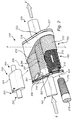
- Fig. 2 in conjunction with Fig. 3a-c illustrates a combined heat exchanger and exhaust silencer 200 according to an embodiment of the invention.
- the combined heat exchanger and exhaust silencer 200 has an inlet 202 though which exhaust gas may enter the combined heat exchanger and exhaust silencer 200 (originating from e.g. the ICE 102 or catalytic converter 104), and an outlet 204 through which exhaust gas may exit the combined heat exchanger and exhaust silencer 200.
- bypass pipe 206 having a perforated wall portion 207, the wall portion 207 of the bypass pipe 206 has a plurality of radial through holes into the interior of the bypass pipe 206.
- the bypass pipe 206 defines a flow channel (not shown, see Fig. 3c ) for the exhaust gas though the housing 201 in a bypass state.
- a second pipe 210 arranged in the housing 201, the second pipe 210 also having a perforated wall, in this embodiment the entire second pipe is perforated (the second pipe may also only be partly perforated in other embodiments).
- the second pipe 210 extends from the first end portion 203 to the second end portion 205 of the housing 201.
- the third pipe 212 also has a perforated wall and extends form the from the first end portion 203 to the second end portion 205 of the housing 201. In this embodiment the entire third pipe is perforated (the second pipe may also only be partly perforated in other embodiments). Furthermore, the third pipe has a larger inner diameter than the outer diameter of the second pipe 206. This enables for the second pipe 210 to be arranged inside the third pipe 212. For example, the second 210 and the third pipe 212 may be concentrically arranged.
- a heat exchanger pipe 216 is arranged as a spiral around the second pipe 210 for defining a flow channel for a heat exchanging fluid comprising e.g. water, oil, glycol, ethanol, methanol or combinations of e.g. water/glycol, water/ethanol, or water/methanol etc. known in the art.
- the heat exchanger pipe 216 is arranged in the second flow channel 303 such that the heat in the exhaust gas flowing in the second flow channel may be transferred to the heat exchanging fluid in the heat exchanger pipe 216.
- the heat exchanger pipe 216 is provided in the form of a double helical coil e.g. a helical shaped pipe wound around the second pipe 210.
- the bypass pipe 206, and the third pipe 210 may be held in place in the housing by a mounting plate 230 rigidly attached to the housing by e.g. welding or by screws.
- the second pipe 210 may be mounted to a front wall 227 and a rear wall 225.
- a bypass valve 220 (see also Fig. 3a-c ) is arranged in this embodiment on the bypass pipe 206.
- the bypass valve 220 is configured to open and close a flow path for the exhaust gas from the inlet 202 to the outlet 204 via the bypass pipe 206.
- the bypass valve in a first state, is configured to allow a flow path for exhaust gas to be open from the inlet 202 to the outlet 204 via the flow channel 302 of the bypass pipe 206.
- the bypass valve In a second state, the bypass valve is configured to close the flow path, whereby at least a main portion of the exhaust gas is forced through the second flow channel 303.
- the bypass valve 220 closes the flow path inside the bypass pipe 206.
- the bypass valve 220 may be located outside the bypass pipe 206, for example at the inlet before the bypass pipe 206 in the exhaust gas flow to direction the exhaust gas to the bypass pipe 206 in the first state and to the second flow channel 303 in the second state.
- a sound absorbing material 218 such as glass fiber wool is arranged surrounding the bypass pipe 206 and the third pipe 212. Furthermore, sound absorbing material 218 is also arranged inside the second pipe 210. Preferably, the sound absorbing material 218 fills the housing from the first end portion 203 to the second end portion 205 and the inside of the second pipe 212. This improves the sound silencing effect of the combined heat exchanger and exhaust silencer 200 in both the bypass state and in the second state (the heat exchanging state).
- the housing has a shape with an oval cross-section, however, other shapes are possible (e.g. circular, rectangular, etc.).
- the inlet and the outlet may be part of the housing, or as shown in Fig. 2 , the inlet 202 may be part of a front wall 225 and the outlet may be part of a rear wall 227, the front wall and the rear wall being mounted to close the housing 201 the first end portion 203 and the second end portion 205.
- the inlet and the outlet may be a through hole through the respective wall, and may comprise additional piping if necessary.
- the front wall 225 and the rear wall 227 may be secured to the housing by e.g. screws or by welding.
- the axial length of the second pipe 210 is such that the second pipe 210 extends from the front wall 225 to the rear wall 227, thus maximizing the length of the second pipe 210 in the housing to thereby enable a longer heat exchanger pipe 216 and improved sound silencing in the second state (heat exchanging state).
- the bypass pipe 206 is shorter than the length of the housing such that spacing 222 is formed between the front wall 225 and the bypass pipe 206 and a spacing 223 between the rear wall 227 and the bypass pipe 206.
- the third pipe 212 is shorter than the length of the housing.
- exhaust gas can flow from the inlet 202 to the second flow channel 303 and from the second flow channel 303 to the outlet 204 via a respective spacing 222, 223 at the end portions of the bypass pipe 206 and the front wall 225 and the rear wall 227.
- the embodiments shown herein is shown with two heat exchanging units 250, each comprising a second pipe 210, a third pipe 212 and a heat exchanger pipe 216.
- the invention is equally applicable with a single heat exchanging unit or with more than two heat exchanging units, such as three, four, five heat exchanging units, etc.
- the two heat exchanging units are arranged on opposite sides of the bypass pipe substantially in parallel with the bypass pipe 216.
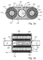
- Fig. 3a illustrates a cross-section of the combined heat exchanger and exhaust silencer 200 along A-A'.
- the second pipe 210 is axially arranged inside the third pipe 212.
- the spacing forming the second flow channel 303 is formed between the second 210 and the third pipe 212.
- the heat exchanger pipe 216 is arranged in the second flow channel 303.
- sound absorbing material 218 surrounds the bypass pipe 206 and the third pipe 212, and sound absorbing material further fills the inside 219 of the second pipe 210.
- Fig. 3b-c shows a cross-section along B-B' of the combined heat exchanger and exhaust silencer 200 being in two different states, in the first state being a bypass state ( Fig. 3b ) and a second state being a heat exchanger state ( Fig. 3c ).
- the bypass valve is in the first state in which the bypass valve 220 is open.
- a bypass state the exhaust gas indicated by arrows, enters the inlet 202 and the main part of the exhaust gas will flow through the first flow channel 302 defined by the first pipe 206.
- the first flow channel is the path of lowest resistance for the exhaust gas in the first state, thus the main portion of the exhaust gas will flow through the bypass pipe 206 in the first flow channel 302.
- a portion of the exhaust gas may flow though the second flow channel 303 since the second flow channel 303 is open.
- the perforations allow for sound waves to penetrate outside of the first pipe 206 and be absorbed by the sound absorbing material 218 (e.g. glass fiber wool). In other words, sound silencing is efficiently accomplished in the first state of the bypass valve 220.
- FIG. 3c illustrating a cross-section of the combined heat exchanger and exhaust silencer 200 with the bypass valve 220 in the second state in which the flow path going through the first flow channel is closed.
- the exhaust gas enters the inlet 202 and is forced to the second flow channel 303 since the first flow channel 302 is closed.
- the perforations of the second pipe 210 and the third pipe 212 allows the sound waves to penetrate though the pipes 210, 212 and be at least partly absorbed by the surrounding sound absorbing material 218, and the sound absorbing material in the second pipe 210.
- the sound absorbing material 218 in the second pipe 210 closes the path through the second pipe 206, thereby further forcing the exhaust gas to flow through the second flow channel 303 where the heat exchanger pipe 216 is located.
- the heat exchanger pipe 216 which is made from a heat conducting material such as steel, stainless steel or any other metal compliant with the heat exchanging fluid.
- the heat exchanging fluid e.g. water, oil, glycol, ethanol, methanol or combinations of e.g. water/glycol, water/ethanol, or water/methanol etc. known in the art
- the heat exchanging fluid has a relatively low temperature when it enters the heat exchanger pipe 216 where it is heated by the relatively high temperature exhaust gas.
- the temperature of the heat exchanging fluid is higher when it leaves the heat exchanger pipe 216 compared to the temperature it had when it entered the heat exchanger pipe 216.
- the bypass valve may be only partly closed such that exhaust gas flows through both the first flow channel 302 and the second flow channel 303. In this way the, flow of exhaust gas and thus heat to the heat exchanger pipe 216 may be controlled.
- the double helical type heat exchanger pipe 216 is advantageous since it increases the contact area between the exhaust gas and heat exchanger pipe and it increases the length of the flow path for the heat exchanging fluid compared to in a single wound heat exchanger pipe, thereby improving the efficiency of the heat exchanger. Furthermore, since the temperature range in an exhaust system of a vehicle can range from about - 50oC to about 2000oC, the parts of the exhaust system will be subject to thermal expansion.
- the double helical type heat exchanger pipe 216 has a spring-like formation which advantageously allows for thermal expansion with small risk of breakage.
- FIG. 4 illustrating a heat exchanger pipe 416 of a combined heat exchanger and exhaust silencer 200 according to an embodiment.
- This heat exchanger pipe 416 comprises cooling fins 420 on the outer surface of the heat exchanger pipe 416.
- the cooling fins 420 further increases the outer surface area of the heat exchanger pipe 416 thus improving the efficiency of the heat exchanger further, i.e. the contact area between the exhaust gas and the heat exchanger pipe 416 is increased by the cooling fins 420.
- the cooling fins 420 shown in Fig. 4 are longitudinal cooling fins 420 substantially parallel the main pipe body 415. Naturally, other types of cooling fins are possible and within the scope of the invention, for example a spiral cooling fins annularly arranged in spiral manner around the main pipe body 415.
- Each of the flanges may be in one piece along the entire heat exchanger pipe. Alternatively or additionally, each of the cooling fins may be in cut in several pieces along the entire heat exchanger pipe.
- the heat exchanger pipe may for example have a diameter selected from the range of 4 mm to 13 mm.
- the bypass pipe 206 may have an inner diameter selected from the range of 30 mm to 90 mm.
- the third pipe 512 comprises a non-perforated wall portion 514 for collecting condensate liquid (e.g. comprising water) at the second end portion 205 of the housing.
- the wall portion 514 which is not perforated thus forms a rounded portion which may collect and hold liquid.
- the condensate liquid may be transferred away from the combined heat exchanger and exhaust silencer 200 by additional tubing (not shown).
- Fig. 6 shows a cross-section of another embodiment in which a three-way bypass valve arrangement including the bypass valve 220 and a second valve 620.
- the second valve 620 arranged to open and close the flow through the second flow channel 303 (here only one of the flow channels 303 has a respective valve, but naturally both heat exchanging units may comprise a respective second valve) and is be arranged such that in the first state the second flow path from the inlet to the outlet via the second flow channel 303 is closed.
- the numbered parts of the embodiment shown in Fig. 6 are the same as the numbered parts already discussed with reference to Figs. 3a-c and Fig. 2 and are not further discussed here.
- the bypass valves 220 or 620 are actuated by e.g. an electric motor (not shown) or a pneumatic motor (not shown).
- the electric motor is preferred; however a pneumatic motor may be advantageous in case of excessive temperatures close to the valves.
- the actuator e.g. the electric motor
- the actuator is controlled by a control unit (not shown) to open or close the bypass valve based on for example the need for heat recovery and/or to protect the heat exchanger unit 250 from overheating.
- a lever 221 for the bypass valve extends outside the housing 201 such that the state of the bypass valve can be controlled by an external actuator (not shown).
- a control unit may include a microprocessor, microcontroller, programmable digital signal processor or another programmable device.
- bypass pipe may be arranged inside the second pipe.
- the bypass pipe, the second pipe and the third pipe may all be concentrically arranged.
Landscapes
- Engineering & Computer Science (AREA)
- Chemical & Material Sciences (AREA)
- Combustion & Propulsion (AREA)
- Mechanical Engineering (AREA)
- General Engineering & Computer Science (AREA)
- Exhaust Silencers (AREA)
Abstract
Description
- The present invention relates to a combined heat exchanger and exhaust silencer for a vehicle.
- Generally, an internal combustion engine of a vehicle is equipped with an exhaust system. The exhaust system functions to reduce the noise from the engine while emitting the exhaust out from the engine. To reduce the noise an exhaust silencer is arranged to define a path for the exhaust gas such that the noise is reduced. Furthermore, the exhaust system may also comprise a catalytic converter for converting toxic gases in the exhaust gas to less toxic gases.
- Heat from the exhaust gas may be recovered from the exhaust gas and be used for e.g. heating the cabin of the vehicle, the coolant in the radiator, the engine oil or the transmission oil in a so called heat-to-heat device. The recovered heat may also be used to produce electric energy or to provide additional power to the drive line of the vehicle using a heat-to-power device. For recovering the heat from the exhaust gas, a heat exchanger may be located as part of the exhaust system. In such heat exchanger for an internal combustion engine, heat is transferred from exhaust gas to a working media such as a fluid. The heat exchanger can be of various designs, such as tube or plate heat exchangers. However, heat exchangers are bulky, and space conflicts often occur if these heat exchangers are integrated in the exhaust line. Normally, also a bypass is required to switch off the waste heat recovery system at higher engine loads.
-
EP2733322 describes a heat exchanger for an exhaust system. InEP2733322 , there is shown that heat exchanger pipes are arranged along a first path for the exhaust gas and there is also shown a bypass path in which the exhaust gas bypasses the heat exchanger pipes. However, improvements appear to be possible with relation to the heat exchanger efficiency and further also in relation to noise reduction in the bypass path. - Thus, there appear to be room for improvements over prior art exhaust systems having an integrated heat exchanger.
- In view of above-mentioned and other drawbacks of the prior art, it is an object of the present invention to provide a combined heat exchanger and exhaust silencer that alleviates at least part of the problem with prior art systems.
- According to a first aspect of the invention, there is provided a combined heat exchanger and exhaust silencer for a vehicle, comprising: an inlet and an outlet for an exhaust gas flow; a housing arranged with a first end portion at the inlet and a second end portion at the outlet such that the exhaust gas can flow through the housing; a bypass pipe arranged in the housing, the bypass pipe having a perforated wall portion, the bypass pipe defining a first flow channel for the exhaust gas through the housing; a second pipe arranged in the housing, the second pipe having a perforated wall portion, the second pipe being arranged extend from the first end portion to the second end portion of the housing; a third pipe arranged in the housing, the third pipe having a perforated wall portion, the third pipe being arranged extend from the first end portion to the second end portion of the housing, the third pipe having a larger inner diameter than an outer diameter of the second pipe, wherein the second pipe is arranged in the third pipe such that a space between an outer surface of the second pipe and an inner surface of the third pipe defines a second flow channel for the exhaust gas through the housing; a heat exchanger pipe for defining a flow channel for a heat exchanging fluid, the heat exchanger pipe arranged as a spiral around the periphery of the second pipe, in the second flow channel, a sound absorbing material arranged in the housing and surrounding the bypass pipe and the third pipe, the sound absorbing material further being arranged inside the second pipe; a bypass valve configured to: in a first state, allow a flow path for exhaust gas to be open from the inlet to the outlet via the flow channel of the bypass pipe, and in a second state, close the flow path, whereby at least a main portion of the exhaust gas is forced through the second flow channel.
- The perforated wall portions of the pipes comprise punched holes forming through-holes in the material of the pipes. The holes extend between an interior and the exterior of the pipe.
- The bypass valve is configured to be switchable between at least the first state and the second state. The first state may generally be a "bypass state" in which the flow of exhaust gas is bypassed from flowing through the second flow channel. In the second state, the exhaust gas flows through the second flow channel thereby exchanging heat with the heat exchanger pipe, thus the second state may be a "heat exchanging state". In addition, the bypass valve may be only partly closed such that exhaust gas flows through both the first flow channel and the second flow channel. In this way the flow of exhaust gas and thus heat to the heat exchanger pipe may be controlled.
- The heat exchanger pipe is configured to provide the heat exchanging fluid (i.e. a "cooling medium" or "working fluid") to a heat exchanger unit configured to recover the heat from the heat exchanging fluid. The heat exchanger unit may be e.g. a heat-to-heat device or a heat-to-power device. Thus, the relatively high temperature heat exchanging fluid is transported in the heat exchanger pipe to the heat exchanger unit where the heat is recovered and transferred elsewhere (e.g. to heat certain parts of the vehicle, or transformed to mechanical power to provide power to the drive line).
- The present invention is based on the realization that a heat exchanger may be integrated in an exhaust silencer by including a configurable bypass valve. The bypass valve may control the flow of exhaust gas to flow through a bypass pipe and/or at least one pipe having a heat exchanger pipe arranged around it. The pipes (the bypass pipe, the second pipe and the third pipe) have perforations (e.g. punched holes) and are surrounded by sound absorbing material, in this way, sound absorbing functionality is realized both when the heat exchanger is engaged (second state) and in the bypass state.
- According to an embodiment of the invention, the spiral heat exchanger pipe may be a double helical coil wound around the second pipe, wherein the heat exchanger pipe is wound around the second pipe along substantially the entire length of the second pipe which is located in the housing. The helix type heat exchanger pipe has a spring-like formation which advantageously allows for thermal expansion with small risk of breakage.
- According to an embodiment of the invention, the heat exchanger pipe may comprise cooling fins on the outer surface of the heat exchanger pipe. Thus, in order to further increase the contact area between the heat exchanger pipe and the exhaust gas to thereby improve the efficiency of the heat exchanger, cooling fins are included on the exterior of the heat exchanger pipe.
- According to embodiments of the invention, the sound absorbing material may be further arranged such that it fills the housing from the first end portion to the second end portion of the housing, the sound absorbing material further being arranged to fill the interior of the second pipe at least inside the housing. This way, the sound absorbing functionality is improved in both the first state and the second state of the bypass valve. For example, the sound absorbing functionality is in this way improved over the entire length of at least the housing of the combined heat exchanger and exhaust silencer.
- In one embodiment of the invention, the third pipe may comprise a non-perforated wall portion for collecting condensate liquid at the second end portion of the housing. In the second state, the relatively high temperature exhaust gas enters the second flow channel where the heat exchanger pipe is located at the first end, as the exhaust gas travels along the second flow channel it cools down (i.e. exchanges heat with the heat exchanger pipe) and condensate liquid (e.g. water) may be formed at the second end portion. The non-perforated wall portion which has no punched holes may be configured to collect the condensate liquid.
- The combined heat exchanger and exhaust silencer may comprise a front wall in which the inlet is located and a rear wall in which the outlet is located, the front wall arranged to close the housing at the first end portion and the rear wall is arranged to close the housing at the second end portion. With the front wall and rear wall closing the housing, the inlet and the outlet are configured to allow exhaust gas to enter and exit the housing.
- According to one embodiment of the invention, the axial length of the bypass pipe may be shorter than the length of the housing such that spacing are formed between the end portions of the bypass pipe and the front wall and the rear wall, wherein the axial length of the third pipe may be shorter than the length of the housing such that spacing are formed between the end portions of the third pipe and the front wall and the rear wall, whereby exhaust gas can flow from the inlet to the second flow channel and from the second flow channel to the outlet via a respective spacing at end portions of the bypass pipe and the front wall and the rear wall, and via the spacing at end portions of the third pipe and the front wall and the rear wall. In other words, the second pipe is longer than the third pipe and the bypass pipe. In this way, a path for the exhaust gas is formed into the second flow channel with the spacings.
- In one embodiment, the axial length of the second pipe may be such that the second pipe extends from the front wall to the rear wall.
- The bypass valve may be arranged on several possible locations. One possible implementation is that the bypass valve is arranged to close the first flow path on the bypass pipe. Thus, the bypass valve in arranged in the bypass pipe and is thereby configured to close the first flow path by closing the first flow channel. For example, the bypass valve may be located at the end portion of the bypass pipe near the second end portion of the housing at the rear wall. This way, the bypass valve is not exposed to the relatively high temperature exhaust gas entering the housing through the inlet at the front wall. In another embodiment, the bypass valve may be located at the end portion of the bypass pipe near the first end portion of the housing at the front wall. Thereby, the exhaust gas is not allowed to enter the bypass pipe in the second state.
- In one embodiment, there may be a second valve configured to: in the first state, close a second flow path from the inlet to the outlet via the second flow channel. Thus, the second flow path includes the second flow channel and this second flow path may be closed by the bypass valve in the first state. In this way, the heat exchanging functionality may be at least partly shut off.
- The bypass valve and the second valve may form a three-way valve. Such a valve is able to open a first path while at the same time close a second path.
- The sound absorbing material is advantageously a porous material. For example the sound absorbing material may be glass fiber wool, mineral wool, ceramic wool, or stone wool.
- According to a second aspect of the invention, there is provided a vehicle comprising the combined heat exchanger and exhaust silencer.
- Effects and features of the second aspect of the invention are largely analogous to those described above in connection with the first aspect of the invention.
- In summary, according to various embodiments the present invention relates to a combined heat exchanger and exhaust silencer for a vehicle, comprising a bypass valve configured to: in a first state, allow a flow path for exhaust gas to be open from an inlet to an outlet via an at least partly perforated bypass pipe, and in a second state, close the flow path, whereby at least a main portion of the exhaust gas is forced through a second flow channel comprising a heat exchanger pipe. The second flow channel is formed by an annular space between an at least partly perforated second pipe and an at least partly perforated third pipe. A sound absorbing material surrounds the bypass pipe and the third pipe, and is further arranged inside the second pipe.
- Further features of, and advantages with, the present invention will become apparent when studying the appended claims and the following description. The skilled person realize that different features of the present invention may be combined to create embodiments other than those described in the following, without departing from the scope of the present invention.
- These and other aspects of the present invention will now be described in more detail, with reference to the appended drawings showing example embodiments of the invention, wherein:
-
Fig 1 schematically shows a vehicle according to an example embodiment of the present invention; -
Fig. 2 illustrates a combined heat exchanger and exhaust silencer according to an example embodiment of the invention; -
Fig. 3a is a cross-section of the combined heat exchanger and exhaust silencer inFig. 2 ; -
Fig. 3b is a cross-section of the combined heat exchanger and exhaust silencer inFig. 2 with the bypass valve in a first state; -
Fig. 3c is a cross-section of the combined heat exchanger and exhaust silencer inFig. 2 with the bypass valve in a second state; -
Fig. 4 illustrates an example heat exchanger pipe arranged around a second pipe; -
Fig. 5 illustrates an exemplary embodiment of the invention; and -
Fig. 6 illustrates a cross-section of an exemplary embodiment of the invention. - In the present detailed description, various embodiments of the system and method according to the present invention are mainly described with reference to a vehicle in the form of a car. However, the present invention mainly equally be used for other types of vehicles such as trucks, busses, etc. Thus, this invention may, be embodied in many different forms and should not be construed as limited to the embodiments set forth herein; rather, these embodiments are provided for thoroughness and completeness, and fully convey the scope of the invention to the skilled person. Like reference characters refer to like elements throughout.
-
Fig 1 schematically shows a vehicle in the form of acar 100. Thecar 100 comprises an internal combustion engine (ICE) 102 with its exhaust connected with pipes tocatalytic converter 104. The exhaust gas flows from the ICE to thecatalytic converter 104 which is configured to reduce the amount of toxic gases in the exhaust gas. Subsequently, the exhaust gas flows to a combined heat exchanger andexhaust silencer 106 according to embodiments of the invention. -
Fig. 2 in conjunction withFig. 3a-c illustrates a combined heat exchanger andexhaust silencer 200 according to an embodiment of the invention. The combined heat exchanger andexhaust silencer 200 has aninlet 202 though which exhaust gas may enter the combined heat exchanger and exhaust silencer 200 (originating from e.g. theICE 102 or catalytic converter 104), and anoutlet 204 through which exhaust gas may exit the combined heat exchanger andexhaust silencer 200. There is further ahousing 201 arranged with afirst end portion 203 at theinlet 202 side and asecond end portion 205 at theoutlet 204 side of the combined heat exchanger andexhaust silencer 200, such that the exhaust gas can flow through thehousing 201. Inside the housing there is abypass pipe 206 having aperforated wall portion 207, thewall portion 207 of thebypass pipe 206 has a plurality of radial through holes into the interior of thebypass pipe 206. Thebypass pipe 206 defines a flow channel (not shown, seeFig. 3c ) for the exhaust gas though thehousing 201 in a bypass state. For the heat exchanging part of the combinedsystem 200, there is asecond pipe 210 arranged in thehousing 201, thesecond pipe 210 also having a perforated wall, in this embodiment the entire second pipe is perforated (the second pipe may also only be partly perforated in other embodiments). Thesecond pipe 210 extends from thefirst end portion 203 to thesecond end portion 205 of thehousing 201. This contributes to improved sound silencing in the heat exchanging state (described below). There is further athird pipe 212 in thehousing 201. Thethird pipe 212 also has a perforated wall and extends form the from thefirst end portion 203 to thesecond end portion 205 of thehousing 201. In this embodiment the entire third pipe is perforated (the second pipe may also only be partly perforated in other embodiments). Furthermore, the third pipe has a larger inner diameter than the outer diameter of thesecond pipe 206. This enables for thesecond pipe 210 to be arranged inside thethird pipe 212. For example, the second 210 and thethird pipe 212 may be concentrically arranged. There is thus spacing between the outer surface of thesecond pipe 210 and an inner surface of thethird pipe 212 which defines asecond flow channel 303 for the exhaust gas through thehousing 201. Aheat exchanger pipe 216 is arranged as a spiral around thesecond pipe 210 for defining a flow channel for a heat exchanging fluid comprising e.g. water, oil, glycol, ethanol, methanol or combinations of e.g. water/glycol, water/ethanol, or water/methanol etc. known in the art. Theheat exchanger pipe 216 is arranged in thesecond flow channel 303 such that the heat in the exhaust gas flowing in the second flow channel may be transferred to the heat exchanging fluid in theheat exchanger pipe 216. In this embodiment, theheat exchanger pipe 216 is provided in the form of a double helical coil e.g. a helical shaped pipe wound around thesecond pipe 210. Thebypass pipe 206, and thethird pipe 210 may be held in place in the housing by a mountingplate 230 rigidly attached to the housing by e.g. welding or by screws. Thesecond pipe 210 may be mounted to afront wall 227 and arear wall 225. - With further reference to
Fig. 2 , a bypass valve 220 (see alsoFig. 3a-c ) is arranged in this embodiment on thebypass pipe 206. Thebypass valve 220 is configured to open and close a flow path for the exhaust gas from theinlet 202 to theoutlet 204 via thebypass pipe 206. Thus, in a first state, the bypass valve is configured to allow a flow path for exhaust gas to be open from theinlet 202 to theoutlet 204 via theflow channel 302 of thebypass pipe 206. In a second state, the bypass valve is configured to close the flow path, whereby at least a main portion of the exhaust gas is forced through thesecond flow channel 303. When the exhaust gas flows though the second flow channel, it flows in contact with theheat exchanger pipe 216 such that heat may be transferred from the exhaust gas to the heat exchanger fluid flowing in theheat exchanger pipe 216. In this particular embodiment, thebypass valve 220 closes the flow path inside thebypass pipe 206. However, thebypass valve 220 may be located outside thebypass pipe 206, for example at the inlet before thebypass pipe 206 in the exhaust gas flow to direction the exhaust gas to thebypass pipe 206 in the first state and to thesecond flow channel 303 in the second state. - In addition, a
sound absorbing material 218 such as glass fiber wool is arranged surrounding thebypass pipe 206 and thethird pipe 212. Furthermore,sound absorbing material 218 is also arranged inside thesecond pipe 210. Preferably, thesound absorbing material 218 fills the housing from thefirst end portion 203 to thesecond end portion 205 and the inside of thesecond pipe 212. This improves the sound silencing effect of the combined heat exchanger andexhaust silencer 200 in both the bypass state and in the second state (the heat exchanging state). - In the embodiment shown in
Fig. 2 , the housing has a shape with an oval cross-section, however, other shapes are possible (e.g. circular, rectangular, etc.). Furthermore, the inlet and the outlet may be part of the housing, or as shown inFig. 2 , theinlet 202 may be part of afront wall 225 and the outlet may be part of arear wall 227, the front wall and the rear wall being mounted to close thehousing 201 thefirst end portion 203 and thesecond end portion 205. The inlet and the outlet may be a through hole through the respective wall, and may comprise additional piping if necessary. Thefront wall 225 and therear wall 227 may be secured to the housing by e.g. screws or by welding. - With further reference to
Fig. 2 in combination withFig. 3b-c , the axial length of thesecond pipe 210 is such that thesecond pipe 210 extends from thefront wall 225 to therear wall 227, thus maximizing the length of thesecond pipe 210 in the housing to thereby enable a longerheat exchanger pipe 216 and improved sound silencing in the second state (heat exchanging state). Furthermore, thebypass pipe 206 is shorter than the length of the housing such thatspacing 222 is formed between thefront wall 225 and thebypass pipe 206 and aspacing 223 between therear wall 227 and thebypass pipe 206. Furthermore, thethird pipe 212 is shorter than the length of the housing. With this configuration, exhaust gas can flow from theinlet 202 to thesecond flow channel 303 and from thesecond flow channel 303 to theoutlet 204 via arespective spacing bypass pipe 206 and thefront wall 225 and therear wall 227. - The embodiments shown herein is shown with two
heat exchanging units 250, each comprising asecond pipe 210, athird pipe 212 and aheat exchanger pipe 216. However, the invention is equally applicable with a single heat exchanging unit or with more than two heat exchanging units, such as three, four, five heat exchanging units, etc. InFig. 2 , the two heat exchanging units are arranged on opposite sides of the bypass pipe substantially in parallel with thebypass pipe 216. -
Fig. 3a illustrates a cross-section of the combined heat exchanger andexhaust silencer 200 along A-A'. InFig. 3a there is shown that thesecond pipe 210 is axially arranged inside thethird pipe 212. Further, the spacing forming thesecond flow channel 303 is formed between the second 210 and thethird pipe 212. Theheat exchanger pipe 216 is arranged in thesecond flow channel 303. Furthermore,sound absorbing material 218 surrounds thebypass pipe 206 and thethird pipe 212, and sound absorbing material further fills the inside 219 of thesecond pipe 210. -
Fig. 3b-c shows a cross-section along B-B' of the combined heat exchanger andexhaust silencer 200 being in two different states, in the first state being a bypass state (Fig. 3b ) and a second state being a heat exchanger state (Fig. 3c ). - First with reference to
Fig. 3b , the bypass valve is in the first state in which thebypass valve 220 is open. In this first state, a bypass state, the exhaust gas indicated by arrows, enters theinlet 202 and the main part of the exhaust gas will flow through thefirst flow channel 302 defined by thefirst pipe 206. The first flow channel is the path of lowest resistance for the exhaust gas in the first state, thus the main portion of the exhaust gas will flow through thebypass pipe 206 in thefirst flow channel 302. A portion of the exhaust gas may flow though thesecond flow channel 303 since thesecond flow channel 303 is open. The perforations allow for sound waves to penetrate outside of thefirst pipe 206 and be absorbed by the sound absorbing material 218 (e.g. glass fiber wool). In other words, sound silencing is efficiently accomplished in the first state of thebypass valve 220. - Turing to
Fig. 3c , illustrating a cross-section of the combined heat exchanger andexhaust silencer 200 with thebypass valve 220 in the second state in which the flow path going through the first flow channel is closed. In this second state, the exhaust gas enters theinlet 202 and is forced to thesecond flow channel 303 since thefirst flow channel 302 is closed. The perforations of thesecond pipe 210 and thethird pipe 212 allows the sound waves to penetrate though thepipes sound absorbing material 218, and the sound absorbing material in thesecond pipe 210. Further, thesound absorbing material 218 in thesecond pipe 210 closes the path through thesecond pipe 206, thereby further forcing the exhaust gas to flow through thesecond flow channel 303 where theheat exchanger pipe 216 is located. As the exhaust gas flows through thesecond flow channel 303 it comes in contact with theheat exchanger pipe 216 which is made from a heat conducting material such as steel, stainless steel or any other metal compliant with the heat exchanging fluid. The heat exchanging fluid (e.g. water, oil, glycol, ethanol, methanol or combinations of e.g. water/glycol, water/ethanol, or water/methanol etc. known in the art) flows in the in theheat exchanger pipe 216 from an inlet (not shown) of theheat exchanger pipe 216 to an outlet (not shown). The heat exchanging fluid has a relatively low temperature when it enters theheat exchanger pipe 216 where it is heated by the relatively high temperature exhaust gas. Thus, the temperature of the heat exchanging fluid is higher when it leaves theheat exchanger pipe 216 compared to the temperature it had when it entered theheat exchanger pipe 216. In addition, the bypass valve may be only partly closed such that exhaust gas flows through both thefirst flow channel 302 and thesecond flow channel 303. In this way the, flow of exhaust gas and thus heat to theheat exchanger pipe 216 may be controlled. - The double helical type
heat exchanger pipe 216 is advantageous since it increases the contact area between the exhaust gas and heat exchanger pipe and it increases the length of the flow path for the heat exchanging fluid compared to in a single wound heat exchanger pipe, thereby improving the efficiency of the heat exchanger. Furthermore, since the temperature range in an exhaust system of a vehicle can range from about - 50ºC to about 2000ºC, the parts of the exhaust system will be subject to thermal expansion. The double helical typeheat exchanger pipe 216 has a spring-like formation which advantageously allows for thermal expansion with small risk of breakage. - Turning now to
Fig. 4 illustrating aheat exchanger pipe 416 of a combined heat exchanger andexhaust silencer 200 according to an embodiment. Thisheat exchanger pipe 416 comprises coolingfins 420 on the outer surface of theheat exchanger pipe 416. The coolingfins 420 further increases the outer surface area of theheat exchanger pipe 416 thus improving the efficiency of the heat exchanger further, i.e. the contact area between the exhaust gas and theheat exchanger pipe 416 is increased by the coolingfins 420. The coolingfins 420 shown inFig. 4 arelongitudinal cooling fins 420 substantially parallel themain pipe body 415. Naturally, other types of cooling fins are possible and within the scope of the invention, for example a spiral cooling fins annularly arranged in spiral manner around themain pipe body 415. Each of the flanges may be in one piece along the entire heat exchanger pipe. Alternatively or additionally, each of the cooling fins may be in cut in several pieces along the entire heat exchanger pipe. The heat exchanger pipe may for example have a diameter selected from the range of 4 mm to 13 mm. Thebypass pipe 206 may have an inner diameter selected from the range of 30 mm to 90 mm. - With reference to
Fig. 5 illustrating a further embodiment of the invention in which thethird pipe 512 comprises anon-perforated wall portion 514 for collecting condensate liquid (e.g. comprising water) at thesecond end portion 205 of the housing. Thewall portion 514 which is not perforated thus forms a rounded portion which may collect and hold liquid. The condensate liquid may be transferred away from the combined heat exchanger andexhaust silencer 200 by additional tubing (not shown). -
Fig. 6 shows a cross-section of another embodiment in which a three-way bypass valve arrangement including thebypass valve 220 and asecond valve 620. Thesecond valve 620 arranged to open and close the flow through the second flow channel 303 (here only one of theflow channels 303 has a respective valve, but naturally both heat exchanging units may comprise a respective second valve) and is be arranged such that in the first state the second flow path from the inlet to the outlet via thesecond flow channel 303 is closed. The numbered parts of the embodiment shown inFig. 6 are the same as the numbered parts already discussed with reference toFigs. 3a-c andFig. 2 and are not further discussed here. - The
bypass valves heat exchanger unit 250 from overheating. Alever 221 for the bypass valve extends outside thehousing 201 such that the state of the bypass valve can be controlled by an external actuator (not shown). - A control unit may include a microprocessor, microcontroller, programmable digital signal processor or another programmable device.
- The person skilled in the art realizes that the present invention by no means is limited to the preferred embodiments described above. On the contrary, many modifications and variations are possible within the scope of the appended claims. For example, the bypass pipe may be arranged inside the second pipe. In other words, the bypass pipe, the second pipe and the third pipe may all be concentrically arranged.
- In the claims, the word "comprising" does not exclude other elements or steps, and the indefinite article "a" or "an" does not exclude a plurality. A single processor or other unit may fulfill the functions of several items recited in the claims. The mere fact that certain measures are recited in mutually different dependent claims does not indicate that a combination of these measured cannot be used to advantage. Any reference signs in the claims should not be construed as limiting the scope.
Claims (15)
- A combined heat exchanger and exhaust silencer (200) for a vehicle (100), comprising:an inlet (202) and an outlet (204) for an exhaust gas flow;a housing (201) arranged with a first end portion (203) at said inlet and a second end portion (205) at said outlet such that the exhaust gas can flow through said housing;a bypass pipe (206) arranged in said housing, said bypass pipe having a perforated wall portion (207), said bypass pipe defining a first flow channel (302) for the exhaust gas through said housing;a second pipe (210) arranged in said housing, said second pipe having a perforated wall portion, said second pipe being arranged extend from said first end portion to said second end portion of said housing;a third pipe (212, 512) arranged in said housing, said third pipe having a perforated wall portion, said third pipe being arranged extend from said first end portion to said second end portion of said housing, said third pipe having a larger inner diameter than an outer diameter of said second pipe, wherein said second pipe is arranged in said third pipe such that a space between an outer surface of said second pipe and an inner surface of said third pipe defines a second flow channel (303) for the exhaust gas through said housing;a heat exchanger pipe (216, 416) for defining a flow channel for a heat exchanging fluid, said heat exchanger pipe arranged as a spiral around the periphery of said second pipe, in said second flow channel,a sound absorbing material (218) arranged in said housing and surrounding said bypass pipe and said third pipe, said sound absorbing material further being arranged inside said second pipe;a bypass valve (220) configured to:in a first state, allow a flow path for exhaust gas to be open from said inlet to said outlet via said flow channel of said bypass pipe, andin a second state, close said flow path, whereby at least a main portion of said exhaust gas is forced through said second flow channel.
- The combined heat exchanger and exhaust silencer according to claim 1, wherein said spiral heat exchanger pipe is a double helical coil wound around said second pipe, wherein said heat exchanger pipe is wound around said second pipe along substantially the entire length of said second pipe which is located in said housing.
- The combined heat exchanger and exhaust silencer according to claim 1 or 2, wherein said heat exchanger pipe comprises cooling fins (420) on the outer surface of said heat exchanger pipe.
- The combined heat exchanger and exhaust silencer according to any one of the preceding claims, wherein said sound absorbing material is further arranged to fill the housing from the first end portion to the second end portion of the housing, said sound absorbing material further being arranged to fill the interior of said second pipe at least inside the housing.
- The combined heat exchanger and exhaust silencer according to any one of the preceding claims, wherein said third pipe (512) comprises a non-perforated wall portion (514) for collecting condensate liquid at said second end portion of said housing.
- The combined heat exchanger and exhaust silencer according to any one of the preceding claims, comprising a front wall (225) in which said inlet is located and a rear wall (227) in which said outlet is located, said front wall arranged to close the housing at the first end portion and said rear wall is arranged to close said housing at the second end portion.
- The combined heat exchanger and exhaust silencer according to claim 6, wherein the axial length of said bypass pipe is shorter than the length of the housing such that spacing (222, 223) are formed between the end portions of the bypass pipe and the front wall and the rear wall, wherein the axial length of said third pipe is shorter than the length of the housing such that spacing (222, 223) are formed between the end portions of the third pipe and the front wall and the rear wall,
whereby exhaust gas can flow from the inlet to the second flow channel and from the second flow channel to the outlet via a respective spacing at end portions of the bypass pipe and the front wall and the rear wall, and via the spacing at end portions of the third pipe and the front wall and the rear wall. - The combined heat exchanger and exhaust silencer according to any one of claims 6 or 7, wherein the axial length of said second pipe is such that the second pipe extends from the front wall to the rear wall.
- The combined heat exchanger and exhaust silencer according to any one of the preceding claims, wherein said bypass valve is arranged to close the first flow path on said bypass pipe.
- The combined heat exchanger and exhaust silencer according to claim 9, wherein said bypass valve is located at the end portion of the bypass pipe near the second end portion of the housing at the rear wall.
- The combined heat exchanger and exhaust silencer according to any one of the preceding claims, further comprising a second valve (620) configured to:in said first state, close a second flow path from the inlet to the outlet via said second flow channel.
- The combined heat exchanger and exhaust silencer according to claim 11, wherein the bypass valve and the second valve forms a three-way valve.
- The combined heat exchanger and exhaust silencer according to any one of the preceding claims, wherein said sound absorbing material is glass fiber wool, mineral wool, ceramic wool, or stone wool.
- The combined heat exchanger and exhaust silencer according to any one of the preceding claims, wherein said second pipe, said third pipe and said heat exchanger pipe forms a first heat exchanging unit (250), wherein the combined heat exchanger and exhaust silencer further comprises a second heat exchanger unit, wherein said bypass pipe is arranged between said first heat exchanging unit and said second heat exchanging unit.
- A vehicle (100) comprising the combined heat exchanger and exhaust silencer according to any one of the preceding claims.
Priority Applications (3)
| Application Number | Priority Date | Filing Date | Title |
|---|---|---|---|
| EP16188360.8A EP3293379B1 (en) | 2016-09-12 | 2016-09-12 | Combined heat exchanger and exhaust silencer |
| US15/583,134 US10508580B2 (en) | 2016-09-12 | 2017-05-01 | Combined heat exchanger and exhaust silencer |
| CN201710779573.2A CN107816377B (en) | 2016-09-12 | 2017-09-01 | Combined heat exchanger and exhaust muffler |
Applications Claiming Priority (1)
| Application Number | Priority Date | Filing Date | Title |
|---|---|---|---|
| EP16188360.8A EP3293379B1 (en) | 2016-09-12 | 2016-09-12 | Combined heat exchanger and exhaust silencer |
Publications (2)
| Publication Number | Publication Date |
|---|---|
| EP3293379A1 true EP3293379A1 (en) | 2018-03-14 |
| EP3293379B1 EP3293379B1 (en) | 2019-04-17 |
Family
ID=56896462
Family Applications (1)
| Application Number | Title | Priority Date | Filing Date |
|---|---|---|---|
| EP16188360.8A Active EP3293379B1 (en) | 2016-09-12 | 2016-09-12 | Combined heat exchanger and exhaust silencer |
Country Status (3)
| Country | Link |
|---|---|
| US (1) | US10508580B2 (en) |
| EP (1) | EP3293379B1 (en) |
| CN (1) | CN107816377B (en) |
Families Citing this family (5)
| Publication number | Priority date | Publication date | Assignee | Title |
|---|---|---|---|---|
| WO2017079156A1 (en) * | 2015-11-02 | 2017-05-11 | Roush Enterprises, Inc. | Muffler with selected exhaust pathways |
| DE102016109388A1 (en) * | 2016-05-23 | 2017-11-23 | Eberspächer Exhaust Technology GmbH & Co. KG | Silencer for an exhaust system of an internal combustion engine, in particular for motor vehicles with hybrid drive |
| KR102542945B1 (en) * | 2018-04-24 | 2023-06-15 | 현대자동차주식회사 | Heat exchanger for vehicles |
| JP7023040B2 (en) * | 2019-01-22 | 2022-02-21 | 三恵技研工業株式会社 | Heat exchanger |
| KR102730529B1 (en) * | 2019-05-27 | 2024-11-13 | 현대자동차주식회사 | Exhaust heat recovery system |
Citations (5)
| Publication number | Priority date | Publication date | Assignee | Title |
|---|---|---|---|---|
| WO1997037109A1 (en) * | 1996-03-29 | 1997-10-09 | Ivan Nikitich Vozhenin | Device for muffling noise from a gas stream primarily in an internal combustion engine |
| DE102012202390A1 (en) * | 2012-02-16 | 2013-08-22 | Eberspächer Exhaust Technology GmbH & Co. KG | Heat exchanger device i.e. exhaust gas heat exchanger device, for exhaust system of combustion engine in motor car, has heat exchanger channel enclosing bypass channel, and heat exchanger arranged helically around bypass channel |
| EP2693011A1 (en) * | 2012-07-30 | 2014-02-05 | Benteler Automobiltechnik GmbH | Exhaust gas valve assembly with integrated bypass |
| EP2733322A1 (en) | 2012-11-15 | 2014-05-21 | Magneti Marelli S.p.A. | Exhaust gas heat exchanger with thermal energy recovery for an exhaust system of an internal combustion engine |
| EP2942500A1 (en) * | 2014-05-07 | 2015-11-11 | Benteler Automobiltechnik GmbH | Exhaust gas heat exchanger with bypass tube |
Family Cites Families (18)
| Publication number | Priority date | Publication date | Assignee | Title |
|---|---|---|---|---|
| US2625234A (en) * | 1950-05-10 | 1953-01-13 | Perry B Fina | Valve controlled muffler with a plurality of through passages |
| JP3379254B2 (en) * | 1994-12-26 | 2003-02-24 | 日産自動車株式会社 | Exhaust silencer |
| US6598390B2 (en) * | 2001-12-26 | 2003-07-29 | Liang Fei Industry Co. Ltd. | Easily controlled exhaust pipe |
| JP4566055B2 (en) * | 2004-09-10 | 2010-10-20 | フタバ産業株式会社 | Exhaust heat recovery muffler |
| CN2763532Y (en) * | 2005-01-20 | 2006-03-08 | 张国复 | Silencing heat-exchanger |
| JP2007005178A (en) * | 2005-06-24 | 2007-01-11 | Toyota Motor Corp | Silencer for fuel cell |
| US7610993B2 (en) * | 2005-08-26 | 2009-11-03 | John Timothy Sullivan | Flow-through mufflers with optional thermo-electric, sound cancellation, and tuning capabilities |
| US7673720B2 (en) * | 2006-03-02 | 2010-03-09 | Pacbrake Company | High-performance muffler assembly with multiple modes of operation |
| US20080023264A1 (en) * | 2006-07-27 | 2008-01-31 | Pacini Larry W | Muffler having adjustable butterfly valve for improved sound attenuation and engine performance |
| US8469142B2 (en) * | 2006-08-07 | 2013-06-25 | Zhanzhao Feng | Muffler assembly |
| JP2008232084A (en) | 2007-03-23 | 2008-10-02 | Calsonic Kansei Corp | Exhaust gas heat recovering muffler |
| DE102008001660B4 (en) * | 2007-07-11 | 2025-03-06 | Hanon Systems | heat exchanger |
| CN201517438U (en) * | 2009-10-14 | 2010-06-30 | 芜湖杰锋汽车动力系统有限公司 | Heat transfer exhaust silencer for heating |
| KR101125004B1 (en) * | 2009-12-04 | 2012-03-27 | 기아자동차주식회사 | Exhaust heat recovery apparatus |
| US20110289905A1 (en) * | 2010-06-01 | 2011-12-01 | Delphi Technologies, Inc. | Exhaust gas heat recovery heat exchanger |
| ITBO20100474A1 (en) | 2010-07-27 | 2012-01-28 | Magneti Marelli Spa | SILENCER WITH INTEGRATED HEAT EXCHANGER |
| KR101241211B1 (en) * | 2010-12-09 | 2013-03-13 | 현대자동차주식회사 | Heat exchanger for exhaust heat withdrawal of vehicle |
| WO2017079156A1 (en) * | 2015-11-02 | 2017-05-11 | Roush Enterprises, Inc. | Muffler with selected exhaust pathways |
-
2016
- 2016-09-12 EP EP16188360.8A patent/EP3293379B1/en active Active
-
2017
- 2017-05-01 US US15/583,134 patent/US10508580B2/en active Active
- 2017-09-01 CN CN201710779573.2A patent/CN107816377B/en active Active
Patent Citations (5)
| Publication number | Priority date | Publication date | Assignee | Title |
|---|---|---|---|---|
| WO1997037109A1 (en) * | 1996-03-29 | 1997-10-09 | Ivan Nikitich Vozhenin | Device for muffling noise from a gas stream primarily in an internal combustion engine |
| DE102012202390A1 (en) * | 2012-02-16 | 2013-08-22 | Eberspächer Exhaust Technology GmbH & Co. KG | Heat exchanger device i.e. exhaust gas heat exchanger device, for exhaust system of combustion engine in motor car, has heat exchanger channel enclosing bypass channel, and heat exchanger arranged helically around bypass channel |
| EP2693011A1 (en) * | 2012-07-30 | 2014-02-05 | Benteler Automobiltechnik GmbH | Exhaust gas valve assembly with integrated bypass |
| EP2733322A1 (en) | 2012-11-15 | 2014-05-21 | Magneti Marelli S.p.A. | Exhaust gas heat exchanger with thermal energy recovery for an exhaust system of an internal combustion engine |
| EP2942500A1 (en) * | 2014-05-07 | 2015-11-11 | Benteler Automobiltechnik GmbH | Exhaust gas heat exchanger with bypass tube |
Also Published As
| Publication number | Publication date |
|---|---|
| CN107816377B (en) | 2020-10-23 |
| US10508580B2 (en) | 2019-12-17 |
| CN107816377A (en) | 2018-03-20 |
| EP3293379B1 (en) | 2019-04-17 |
| US20180073412A1 (en) | 2018-03-15 |
Similar Documents
| Publication | Publication Date | Title |
|---|---|---|
| US10508580B2 (en) | Combined heat exchanger and exhaust silencer | |
| CN102062547B (en) | Heat exchanger | |
| US8910471B2 (en) | Structure of exhaust pipe for exhaust heat recovery | |
| JP7101677B2 (en) | Heat recovery device and heat recovery system | |
| EP2743488A1 (en) | Built-in exhaust gas management device | |
| JP7217654B2 (en) | Heat exchanger | |
| US8978745B2 (en) | Exhaust gas heat recovery heat exchanger having a lobed tube coil | |
| JP6854112B2 (en) | Heat exchanger | |
| US20140208725A1 (en) | Heat exchanger of an internal combustion engine | |
| WO2011153179A1 (en) | Exhaust gas heat recovery heat exchanger | |
| CN100573024C (en) | exhaust gas heat exchanger | |
| JP7062621B2 (en) | Heat exchanger | |
| JP2007032561A (en) | Exhaust gas heat recovery device | |
| JP2008232084A (en) | Exhaust gas heat recovering muffler | |
| JP4840408B2 (en) | Cooling water circulation device | |
| JP2011214537A (en) | Exhaust gas heat recovery device | |
| JP4844600B2 (en) | Exhaust heat recovery unit | |
| JP5838406B2 (en) | Exhaust gas heat recovery device | |
| JP4582042B2 (en) | Exhaust heat recovery device with silencer function | |
| US11644252B2 (en) | Flow path structure of heat exchanger, and heat exchanger | |
| JP2007285264A (en) | Heat exchanger | |
| US20060243521A1 (en) | Muffler with improved heat dissipation | |
| KR101307322B1 (en) | Automobile exhaust heat recovery device | |
| JP4291649B2 (en) | Catalytic converter | |
| JP2009287508A (en) | Cooling water circulation system |
Legal Events
| Date | Code | Title | Description |
|---|---|---|---|
| PUAI | Public reference made under article 153(3) epc to a published international application that has entered the european phase |
Free format text: ORIGINAL CODE: 0009012 |
|
| STAA | Information on the status of an ep patent application or granted ep patent |
Free format text: STATUS: THE APPLICATION HAS BEEN PUBLISHED |
|
| AK | Designated contracting states |
Kind code of ref document: A1 Designated state(s): AL AT BE BG CH CY CZ DE DK EE ES FI FR GB GR HR HU IE IS IT LI LT LU LV MC MK MT NL NO PL PT RO RS SE SI SK SM TR |
|
| AX | Request for extension of the european patent |
Extension state: BA ME |
|
| STAA | Information on the status of an ep patent application or granted ep patent |
Free format text: STATUS: REQUEST FOR EXAMINATION WAS MADE |
|
| 17P | Request for examination filed |
Effective date: 20180914 |
|
| RBV | Designated contracting states (corrected) |
Designated state(s): AL AT BE BG CH CY CZ DE DK EE ES FI FR GB GR HR HU IE IS IT LI LT LU LV MC MK MT NL NO PL PT RO RS SE SI SK SM TR |
|
| GRAP | Despatch of communication of intention to grant a patent |
Free format text: ORIGINAL CODE: EPIDOSNIGR1 |
|
| STAA | Information on the status of an ep patent application or granted ep patent |
Free format text: STATUS: GRANT OF PATENT IS INTENDED |
|
| INTG | Intention to grant announced |
Effective date: 20181126 |
|
| GRAS | Grant fee paid |
Free format text: ORIGINAL CODE: EPIDOSNIGR3 |
|
| GRAA | (expected) grant |
Free format text: ORIGINAL CODE: 0009210 |
|
| STAA | Information on the status of an ep patent application or granted ep patent |
Free format text: STATUS: THE PATENT HAS BEEN GRANTED |
|
| AK | Designated contracting states |
Kind code of ref document: B1 Designated state(s): AL AT BE BG CH CY CZ DE DK EE ES FI FR GB GR HR HU IE IS IT LI LT LU LV MC MK MT NL NO PL PT RO RS SE SI SK SM TR |
|
| REG | Reference to a national code |
Ref country code: GB Ref legal event code: FG4D |
|
| REG | Reference to a national code |
Ref country code: CH Ref legal event code: EP |
|
| REG | Reference to a national code |
Ref country code: DE Ref legal event code: R096 Ref document number: 602016012482 Country of ref document: DE |
|
| REG | Reference to a national code |
Ref country code: AT Ref legal event code: REF Ref document number: 1121788 Country of ref document: AT Kind code of ref document: T Effective date: 20190515 Ref country code: IE Ref legal event code: FG4D |
|
| REG | Reference to a national code |
Ref country code: NL Ref legal event code: MP Effective date: 20190417 |
|
| REG | Reference to a national code |
Ref country code: LT Ref legal event code: MG4D |
|
| PG25 | Lapsed in a contracting state [announced via postgrant information from national office to epo] |
Ref country code: NL Free format text: LAPSE BECAUSE OF FAILURE TO SUBMIT A TRANSLATION OF THE DESCRIPTION OR TO PAY THE FEE WITHIN THE PRESCRIBED TIME-LIMIT Effective date: 20190417 |
|
| PG25 | Lapsed in a contracting state [announced via postgrant information from national office to epo] |
Ref country code: FI Free format text: LAPSE BECAUSE OF FAILURE TO SUBMIT A TRANSLATION OF THE DESCRIPTION OR TO PAY THE FEE WITHIN THE PRESCRIBED TIME-LIMIT Effective date: 20190417 Ref country code: LT Free format text: LAPSE BECAUSE OF FAILURE TO SUBMIT A TRANSLATION OF THE DESCRIPTION OR TO PAY THE FEE WITHIN THE PRESCRIBED TIME-LIMIT Effective date: 20190417 Ref country code: PT Free format text: LAPSE BECAUSE OF FAILURE TO SUBMIT A TRANSLATION OF THE DESCRIPTION OR TO PAY THE FEE WITHIN THE PRESCRIBED TIME-LIMIT Effective date: 20190817 Ref country code: ES Free format text: LAPSE BECAUSE OF FAILURE TO SUBMIT A TRANSLATION OF THE DESCRIPTION OR TO PAY THE FEE WITHIN THE PRESCRIBED TIME-LIMIT Effective date: 20190417 Ref country code: HR Free format text: LAPSE BECAUSE OF FAILURE TO SUBMIT A TRANSLATION OF THE DESCRIPTION OR TO PAY THE FEE WITHIN THE PRESCRIBED TIME-LIMIT Effective date: 20190417 Ref country code: AL Free format text: LAPSE BECAUSE OF FAILURE TO SUBMIT A TRANSLATION OF THE DESCRIPTION OR TO PAY THE FEE WITHIN THE PRESCRIBED TIME-LIMIT Effective date: 20190417 Ref country code: SE Free format text: LAPSE BECAUSE OF FAILURE TO SUBMIT A TRANSLATION OF THE DESCRIPTION OR TO PAY THE FEE WITHIN THE PRESCRIBED TIME-LIMIT Effective date: 20190417 Ref country code: NO Free format text: LAPSE BECAUSE OF FAILURE TO SUBMIT A TRANSLATION OF THE DESCRIPTION OR TO PAY THE FEE WITHIN THE PRESCRIBED TIME-LIMIT Effective date: 20190717 |
|
| PG25 | Lapsed in a contracting state [announced via postgrant information from national office to epo] |
Ref country code: PL Free format text: LAPSE BECAUSE OF FAILURE TO SUBMIT A TRANSLATION OF THE DESCRIPTION OR TO PAY THE FEE WITHIN THE PRESCRIBED TIME-LIMIT Effective date: 20190417 Ref country code: GR Free format text: LAPSE BECAUSE OF FAILURE TO SUBMIT A TRANSLATION OF THE DESCRIPTION OR TO PAY THE FEE WITHIN THE PRESCRIBED TIME-LIMIT Effective date: 20190718 Ref country code: LV Free format text: LAPSE BECAUSE OF FAILURE TO SUBMIT A TRANSLATION OF THE DESCRIPTION OR TO PAY THE FEE WITHIN THE PRESCRIBED TIME-LIMIT Effective date: 20190417 Ref country code: BG Free format text: LAPSE BECAUSE OF FAILURE TO SUBMIT A TRANSLATION OF THE DESCRIPTION OR TO PAY THE FEE WITHIN THE PRESCRIBED TIME-LIMIT Effective date: 20190717 Ref country code: RS Free format text: LAPSE BECAUSE OF FAILURE TO SUBMIT A TRANSLATION OF THE DESCRIPTION OR TO PAY THE FEE WITHIN THE PRESCRIBED TIME-LIMIT Effective date: 20190417 |
|
| REG | Reference to a national code |
Ref country code: AT Ref legal event code: MK05 Ref document number: 1121788 Country of ref document: AT Kind code of ref document: T Effective date: 20190417 |
|
| PG25 | Lapsed in a contracting state [announced via postgrant information from national office to epo] |
Ref country code: IS Free format text: LAPSE BECAUSE OF FAILURE TO SUBMIT A TRANSLATION OF THE DESCRIPTION OR TO PAY THE FEE WITHIN THE PRESCRIBED TIME-LIMIT Effective date: 20190817 |
|
| REG | Reference to a national code |
Ref country code: DE Ref legal event code: R097 Ref document number: 602016012482 Country of ref document: DE |
|
| PG25 | Lapsed in a contracting state [announced via postgrant information from national office to epo] |
Ref country code: RO Free format text: LAPSE BECAUSE OF FAILURE TO SUBMIT A TRANSLATION OF THE DESCRIPTION OR TO PAY THE FEE WITHIN THE PRESCRIBED TIME-LIMIT Effective date: 20190417 Ref country code: SK Free format text: LAPSE BECAUSE OF FAILURE TO SUBMIT A TRANSLATION OF THE DESCRIPTION OR TO PAY THE FEE WITHIN THE PRESCRIBED TIME-LIMIT Effective date: 20190417 Ref country code: CZ Free format text: LAPSE BECAUSE OF FAILURE TO SUBMIT A TRANSLATION OF THE DESCRIPTION OR TO PAY THE FEE WITHIN THE PRESCRIBED TIME-LIMIT Effective date: 20190417 Ref country code: DK Free format text: LAPSE BECAUSE OF FAILURE TO SUBMIT A TRANSLATION OF THE DESCRIPTION OR TO PAY THE FEE WITHIN THE PRESCRIBED TIME-LIMIT Effective date: 20190417 Ref country code: EE Free format text: LAPSE BECAUSE OF FAILURE TO SUBMIT A TRANSLATION OF THE DESCRIPTION OR TO PAY THE FEE WITHIN THE PRESCRIBED TIME-LIMIT Effective date: 20190417 Ref country code: AT Free format text: LAPSE BECAUSE OF FAILURE TO SUBMIT A TRANSLATION OF THE DESCRIPTION OR TO PAY THE FEE WITHIN THE PRESCRIBED TIME-LIMIT Effective date: 20190417 |
|
| PLBE | No opposition filed within time limit |
Free format text: ORIGINAL CODE: 0009261 |
|
| STAA | Information on the status of an ep patent application or granted ep patent |
Free format text: STATUS: NO OPPOSITION FILED WITHIN TIME LIMIT |
|
| PG25 | Lapsed in a contracting state [announced via postgrant information from national office to epo] |
Ref country code: SM Free format text: LAPSE BECAUSE OF FAILURE TO SUBMIT A TRANSLATION OF THE DESCRIPTION OR TO PAY THE FEE WITHIN THE PRESCRIBED TIME-LIMIT Effective date: 20190417 |
|
| 26N | No opposition filed |
Effective date: 20200120 |
|
| PG25 | Lapsed in a contracting state [announced via postgrant information from national office to epo] |
Ref country code: TR Free format text: LAPSE BECAUSE OF FAILURE TO SUBMIT A TRANSLATION OF THE DESCRIPTION OR TO PAY THE FEE WITHIN THE PRESCRIBED TIME-LIMIT Effective date: 20190417 |
|
| PG25 | Lapsed in a contracting state [announced via postgrant information from national office to epo] |
Ref country code: SI Free format text: LAPSE BECAUSE OF FAILURE TO SUBMIT A TRANSLATION OF THE DESCRIPTION OR TO PAY THE FEE WITHIN THE PRESCRIBED TIME-LIMIT Effective date: 20190417 Ref country code: MC Free format text: LAPSE BECAUSE OF FAILURE TO SUBMIT A TRANSLATION OF THE DESCRIPTION OR TO PAY THE FEE WITHIN THE PRESCRIBED TIME-LIMIT Effective date: 20190417 |
|
| REG | Reference to a national code |
Ref country code: CH Ref legal event code: PL |
|
| PG25 | Lapsed in a contracting state [announced via postgrant information from national office to epo] |
Ref country code: IE Free format text: LAPSE BECAUSE OF NON-PAYMENT OF DUE FEES Effective date: 20190912 Ref country code: LI Free format text: LAPSE BECAUSE OF NON-PAYMENT OF DUE FEES Effective date: 20190930 Ref country code: CH Free format text: LAPSE BECAUSE OF NON-PAYMENT OF DUE FEES Effective date: 20190930 Ref country code: LU Free format text: LAPSE BECAUSE OF NON-PAYMENT OF DUE FEES Effective date: 20190912 |
|
| REG | Reference to a national code |
Ref country code: BE Ref legal event code: MM Effective date: 20190930 |
|
| PG25 | Lapsed in a contracting state [announced via postgrant information from national office to epo] |
Ref country code: BE Free format text: LAPSE BECAUSE OF NON-PAYMENT OF DUE FEES Effective date: 20190930 |
|
| GBPC | Gb: european patent ceased through non-payment of renewal fee |
Effective date: 20200912 |
|
| PG25 | Lapsed in a contracting state [announced via postgrant information from national office to epo] |
Ref country code: CY Free format text: LAPSE BECAUSE OF FAILURE TO SUBMIT A TRANSLATION OF THE DESCRIPTION OR TO PAY THE FEE WITHIN THE PRESCRIBED TIME-LIMIT Effective date: 20190417 |
|
| PG25 | Lapsed in a contracting state [announced via postgrant information from national office to epo] |
Ref country code: HU Free format text: LAPSE BECAUSE OF FAILURE TO SUBMIT A TRANSLATION OF THE DESCRIPTION OR TO PAY THE FEE WITHIN THE PRESCRIBED TIME-LIMIT; INVALID AB INITIO Effective date: 20160912 Ref country code: MT Free format text: LAPSE BECAUSE OF FAILURE TO SUBMIT A TRANSLATION OF THE DESCRIPTION OR TO PAY THE FEE WITHIN THE PRESCRIBED TIME-LIMIT Effective date: 20190417 |
|
| PG25 | Lapsed in a contracting state [announced via postgrant information from national office to epo] |
Ref country code: GB Free format text: LAPSE BECAUSE OF NON-PAYMENT OF DUE FEES Effective date: 20200912 |
|
| PG25 | Lapsed in a contracting state [announced via postgrant information from national office to epo] |
Ref country code: MK Free format text: LAPSE BECAUSE OF FAILURE TO SUBMIT A TRANSLATION OF THE DESCRIPTION OR TO PAY THE FEE WITHIN THE PRESCRIBED TIME-LIMIT Effective date: 20190417 |
|
| P01 | Opt-out of the competence of the unified patent court (upc) registered |
Effective date: 20231212 |
|
| PGFP | Annual fee paid to national office [announced via postgrant information from national office to epo] |
Ref country code: IT Payment date: 20240820 Year of fee payment: 9 |
|
| PGFP | Annual fee paid to national office [announced via postgrant information from national office to epo] |
Ref country code: DE Payment date: 20250820 Year of fee payment: 10 |
|
| PGFP | Annual fee paid to national office [announced via postgrant information from national office to epo] |
Ref country code: FR Payment date: 20250820 Year of fee payment: 10 |