EP3293356B1 - Aube rotorique pour turbomachine comprenant une tôle de refroidissement par impact mobile et procédé d'assemblage correspondant - Google Patents
Aube rotorique pour turbomachine comprenant une tôle de refroidissement par impact mobile et procédé d'assemblage correspondant Download PDFInfo
- Publication number
- EP3293356B1 EP3293356B1 EP17189024.7A EP17189024A EP3293356B1 EP 3293356 B1 EP3293356 B1 EP 3293356B1 EP 17189024 A EP17189024 A EP 17189024A EP 3293356 B1 EP3293356 B1 EP 3293356B1
- Authority
- EP
- European Patent Office
- Prior art keywords
- impingement cooling
- blade
- cooling device
- connection
- impingement
- Prior art date
- Legal status (The legal status is an assumption and is not a legal conclusion. Google has not performed a legal analysis and makes no representation as to the accuracy of the status listed.)
- Active
Links
- 238000000034 method Methods 0.000 title claims description 5
- 238000001816 cooling Methods 0.000 claims description 194
- 239000002826 coolant Substances 0.000 claims description 28
- 230000000694 effects Effects 0.000 description 5
- 238000002485 combustion reaction Methods 0.000 description 3
- 239000011248 coating agent Substances 0.000 description 2
- 238000000576 coating method Methods 0.000 description 2
- 238000009826 distribution Methods 0.000 description 2
- 239000000463 material Substances 0.000 description 2
- 238000005476 soldering Methods 0.000 description 2
- 238000005219 brazing Methods 0.000 description 1
- 230000010339 dilation Effects 0.000 description 1
- 229910001026 inconel Inorganic materials 0.000 description 1
- 238000004519 manufacturing process Methods 0.000 description 1
- 238000002844 melting Methods 0.000 description 1
- 230000008018 melting Effects 0.000 description 1
- 230000006641 stabilisation Effects 0.000 description 1
- 238000011105 stabilization Methods 0.000 description 1
- 238000003860 storage Methods 0.000 description 1
- 230000035882 stress Effects 0.000 description 1
- 230000008646 thermal stress Effects 0.000 description 1
Images


Classifications
-
- F—MECHANICAL ENGINEERING; LIGHTING; HEATING; WEAPONS; BLASTING
- F01—MACHINES OR ENGINES IN GENERAL; ENGINE PLANTS IN GENERAL; STEAM ENGINES
- F01D—NON-POSITIVE DISPLACEMENT MACHINES OR ENGINES, e.g. STEAM TURBINES
- F01D5/00—Blades; Blade-carrying members; Heating, heat-insulating, cooling or antivibration means on the blades or the members
- F01D5/12—Blades
- F01D5/14—Form or construction
- F01D5/18—Hollow blades, i.e. blades with cooling or heating channels or cavities; Heating, heat-insulating or cooling means on blades
- F01D5/187—Convection cooling
- F01D5/188—Convection cooling with an insert in the blade cavity to guide the cooling fluid, e.g. forming a separation wall
- F01D5/189—Convection cooling with an insert in the blade cavity to guide the cooling fluid, e.g. forming a separation wall the insert having a tubular cross-section, e.g. airfoil shape
-
- F—MECHANICAL ENGINEERING; LIGHTING; HEATING; WEAPONS; BLASTING
- F05—INDEXING SCHEMES RELATING TO ENGINES OR PUMPS IN VARIOUS SUBCLASSES OF CLASSES F01-F04
- F05D—INDEXING SCHEME FOR ASPECTS RELATING TO NON-POSITIVE-DISPLACEMENT MACHINES OR ENGINES, GAS-TURBINES OR JET-PROPULSION PLANTS
- F05D2220/00—Application
- F05D2220/30—Application in turbines
- F05D2220/32—Application in turbines in gas turbines
- F05D2220/323—Application in turbines in gas turbines for aircraft propulsion, e.g. jet engines
-
- F—MECHANICAL ENGINEERING; LIGHTING; HEATING; WEAPONS; BLASTING
- F05—INDEXING SCHEMES RELATING TO ENGINES OR PUMPS IN VARIOUS SUBCLASSES OF CLASSES F01-F04
- F05D—INDEXING SCHEME FOR ASPECTS RELATING TO NON-POSITIVE-DISPLACEMENT MACHINES OR ENGINES, GAS-TURBINES OR JET-PROPULSION PLANTS
- F05D2230/00—Manufacture
- F05D2230/60—Assembly methods
-
- F—MECHANICAL ENGINEERING; LIGHTING; HEATING; WEAPONS; BLASTING
- F05—INDEXING SCHEMES RELATING TO ENGINES OR PUMPS IN VARIOUS SUBCLASSES OF CLASSES F01-F04
- F05D—INDEXING SCHEME FOR ASPECTS RELATING TO NON-POSITIVE-DISPLACEMENT MACHINES OR ENGINES, GAS-TURBINES OR JET-PROPULSION PLANTS
- F05D2250/00—Geometry
- F05D2250/10—Two-dimensional
- F05D2250/14—Two-dimensional elliptical
-
- F—MECHANICAL ENGINEERING; LIGHTING; HEATING; WEAPONS; BLASTING
- F05—INDEXING SCHEMES RELATING TO ENGINES OR PUMPS IN VARIOUS SUBCLASSES OF CLASSES F01-F04
- F05D—INDEXING SCHEME FOR ASPECTS RELATING TO NON-POSITIVE-DISPLACEMENT MACHINES OR ENGINES, GAS-TURBINES OR JET-PROPULSION PLANTS
- F05D2260/00—Function
- F05D2260/20—Heat transfer, e.g. cooling
- F05D2260/201—Heat transfer, e.g. cooling by impingement of a fluid
-
- F—MECHANICAL ENGINEERING; LIGHTING; HEATING; WEAPONS; BLASTING
- F05—INDEXING SCHEMES RELATING TO ENGINES OR PUMPS IN VARIOUS SUBCLASSES OF CLASSES F01-F04
- F05D—INDEXING SCHEME FOR ASPECTS RELATING TO NON-POSITIVE-DISPLACEMENT MACHINES OR ENGINES, GAS-TURBINES OR JET-PROPULSION PLANTS
- F05D2260/00—Function
- F05D2260/20—Heat transfer, e.g. cooling
- F05D2260/202—Heat transfer, e.g. cooling by film cooling
-
- Y—GENERAL TAGGING OF NEW TECHNOLOGICAL DEVELOPMENTS; GENERAL TAGGING OF CROSS-SECTIONAL TECHNOLOGIES SPANNING OVER SEVERAL SECTIONS OF THE IPC; TECHNICAL SUBJECTS COVERED BY FORMER USPC CROSS-REFERENCE ART COLLECTIONS [XRACs] AND DIGESTS
- Y02—TECHNOLOGIES OR APPLICATIONS FOR MITIGATION OR ADAPTATION AGAINST CLIMATE CHANGE
- Y02T—CLIMATE CHANGE MITIGATION TECHNOLOGIES RELATED TO TRANSPORTATION
- Y02T50/00—Aeronautics or air transport
- Y02T50/60—Efficient propulsion technologies, e.g. for aircraft
Definitions
- the invention relates to a rotor blade for a turbo machine, in particular in an aircraft engine, with the features of claim 1 and a method for assembling a rotor blade with the features of claim 14.
- Rotor blades in turbo machines, especially in turbines, are exposed to considerable thermal and also mechanical loads.
- the DE 60 2004 002004 T2 shows blades of turbines which are provided with integrated cooling circuits.
- the EP 0 990 771 A1 describes an impeller blade for a turbine with a cylindrical impact cooling plate, which is connected to the rotor blade via corresponding bearing seats.
- the bearing seats take up a fixing area of the baffle cooling plate rigidly. The inclusion allows radial relative thermal dilation.
- This baffle cooling plate can be made in one or more parts.
- This rotor blade has a cooling device for cooling an area within the rotor blade by means of a cooling medium (in particular cooling air).
- a cooling medium in particular cooling air.
- An impingement cooling device with a large number of impingement cooling openings is used to deflect the cooling medium flowing inside the impingement cooling device to the surface to be cooled outside the impingement cooling device and inside the rotor blade, so that the surface to be cooled can be cooled by means of impingement cooling through the cooling medium emerging from the impingement cooling openings .
- the impingement cooling device is mounted movably with respect to the rotor blade.
- the impingement cooling device is mounted in the area of the moving blade platform opposite the moving blade, this mounting being designed to be axially displaceable by means of a clearance fit or a plain bearing connection. This can serve to compensate for thermal and / or mechanical stresses.
- connection of the impingement cooling device has a form fit at the tip of the rotor blade to prevent rotation, by means of a square connection or as a bayonet connection.
- this impingement cooling device also allows inexpensive manufacture, especially with smaller rotor blades in turbines. Saving cooling air can also improve combustion in an aircraft engine, for example.
- the impingement cooling can be produced in an efficient manner in that the impingement cooling device is arranged at least partially parallel to the surface to be cooled within the rotor blade.
- the cooling medium exiting the impingement cooling openings thus impacts vertically or essentially vertically on the surface to be cooled, the surface to be cooled being arranged in particular on the inside of the blade front edge, since the highest temperatures generally prevail here.
- the impingement cooling device is at least partially designed as a hollow cylinder.
- the cylinder cross-section of the impingement cooling device can, for example, be circular, elliptical, square or polygonal.
- the impingement cooling device extends in one embodiment of a lower connection in the area of a rotor blade platform to the tip of the rotor blade.
- connection of the impingement cooling device at the tip of the rotor blade can be designed in a centering manner, so that the impingement cooling device can return to the centered seat in the event of a small deflection.
- connection of the impingement cooling device at the tip of the rotor blade, in particular between a locking connection piece and the tip has a soldered connection or a welded connection.
- the impingement cooling openings of the impingement cooling device are arranged along the longitudinal axis.
- the density of the impingement cooling openings of the impingement cooling device at the tip of the rotor blade can be at least in a partial area higher than in other areas of the impingement cooling device. The opening density can thus be adapted to the cooling requirements.
- the cooling can also be improved if the impingement cooling openings of the impingement cooling device can be aligned specifically to a region of the surface to be cooled.
- the impingement cooling device can have an elastic thermal compensator, in particular a bellows, on the base of the rotor blade.
- At least one lateral guide element e.g. a rib
- at least one lateral guide element can be used in one embodiment, which is arranged on the outside of the impingement cooling device and / or the inside of the cooling channel for guiding the impingement cooling device.
- the impingement cooling openings of the impingement cooling device have a throttling effect.
- a three-shaft aircraft engine 100 known per se is shown as an example of a turbo machine.
- the aircraft engine 100 has a fan stage 101, a medium-pressure compressor stage 102 and a high-pressure compressor stage 103. These are driven by turbine stages, namely a high pressure turbine 105, a medium pressure turbine 106 and a low pressure turbine 107 in a known manner via a high pressure shaft 108, a medium pressure shaft 109 and a low pressure shaft 110.
- the aircraft engine 100 also has a combustion chamber 104.
- the shafts 108, 109, 110 and parts connected to them rotate about the axis of rotation 111.
- the fan stage 101, the compressor stages 102, 103 and the turbine stages 105, 106, 107 each have numerous rotor blades 10, which add work to the air flowing into the engine 100 or extract work from this air.
- the turbine stages 105, 106, 107 are exposed to high temperatures.
- the hot gas temperatures, in particular at the inlet of the high pressure turbine 105, are partly above the melting point of the blade materials.
- measures for cooling the rotor blades 10 are usually necessary.
- compressor air is used as the cooling medium L, which is guided within the aircraft engine 100 to the base B of a rotor blade 10.
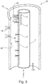
- the rotor blade 10 of a turbine stage 105, 106, 107 is shown in a schematic longitudinal section.
- the base B is connected to a turbine shaft 108, 109, 110, not shown here, via a disk ring 14, which is partially shown here.
- An axial securing ring 15 ensures that the rotor blade 10 is held securely.
- the cooling medium L is guided into the interior of the rotor blade 10 through cooling channels 13A, 13B.
- the cooling medium L is divided into two cooling channels 13A, 13B.
- the first cooling channel 13A leading edge channel
- the first cooling channel 13A extends essentially straight from the base B to the tip S of the rotor blade 10.
- a meandering second cooling channel 13B for convective cooling is arranged in the remainder of the rotor blade 10.
- the cooling medium L partially exits the rotor blade 10 through film cooling openings 12 and cools it from the outside by means of film cooling.
- an additional cooling effect is brought about in the interior of the rotor blade 10 by impingement cooling and an impingement cooling device 1 specially designed for this purpose.
- the cooling medium L is blown directly onto a surface 20 to be cooled inside the rotor blade 10, ie on the inside of the leading edge channel (first cooling channel 13A), especially in the area of the rotor blade leading edge 11.
- first cooling channel 13A leading edge channel
- the impingement cooling device 1 is designed here as a straight hollow cylinder with a constant circular cross section.
- the cross section of the hollow cylinder of the impingement cooling device 1 can also be square, rectangular, polygonal or elliptical.
- the cross-sectional shape and / or area can also change over the length of the impingement cooling device 1, so that in this case there would be a deviation from the cylindrical shape.
- the impingement cooling device 1 can also be tubular with different cross-sectional sizes and / or shapes.
- a radially outwardly directed guide element 4 in the form of a rib is arranged (see also Fig. 5 ). This serves to guide the impingement cooling device 1 inside the first cooling channel 13A.
- a large number of impingement cooling openings 2 are arranged on the outer surface of the here circular cylindrical impingement cooling device 1, the impingement cooling openings 2 pointing here specifically in the direction of the blade leading edge 11 and thus towards the surface 20 to be cooled on the inside of the first cooling channel 13A.
- the impingement cooling openings 2 pointing here specifically in the direction of the blade leading edge 11 and thus towards the surface 20 to be cooled on the inside of the first cooling channel 13A.
- the surface 20 to be cooled is located on the inside of the first cooling channel 13A.
- the cooling medium L is under pressure into the first cooling channel 13A (see Fig. 2 ) and thus also fed into the impingement cooling device 1.
- the cooling medium L flows radially outward within the cylindrical impingement cooling device 1 in the rotor blade 10 and exits laterally through the impingement cooling openings 2 in the lateral surface of the impingement cooling device 1.
- the flow of the cooling medium L is thus deflected by 90 ° and in the form of impingement cooling onto the surface 20 to be cooled on the inside of the first cooling channel 13A guided.
- the angle information and the direction of impact of the cooling medium are to be understood here as mean information, since a flow does not behave like a line.
- Impingement cooling is a very efficient form of convection cooling, in which the cooling medium L collides against the surface 20 to be cooled. A high cooling effect is achieved, especially at the stagnation point of the impact jets. Here the stagnation points lie on the surface 20 to be cooled.
- the density of the impingement cooling openings 2 per unit area is higher at the tip S of the rotor blade 10 than at the base B, since the heat load of the rotor blade 10 increases upwards.
- a homogeneous distribution of the impingement cooling openings 2, a uniformly changing distribution of the impingement cooling openings 2 or a punctiform arrangement of the impingement cooling openings 2 can also be used for targeted cooling of hot partial areas of the surface 20.
- the impingement cooling openings 2 of the impingement cooling device 1 are not aligned with the film cooling openings 12 (only two shown here for reasons of clarity) in the outer wall of the rotor blade 10, but specifically with the wall areas between the film cooling openings 12, since the areas of the surface to be cooled are located there 20 are located.
- a typical outer diameter of the impingement cooling device 1 can be between 3 and 5 mm, with the dimensions being able to be adapted to the cavity in the interior of the rotor blade 10.
- the wall thickness of the impact cooling device 1 can be between 0.2 and 0.5 mm.
- the length of the impingement cooling device 1 can be between 20 and 60 mm, depending on the blade length.
- the gap between the surface 20 to be cooled and the impingement cooling device 1 can be, for example, 1 to 3 mm.
- the cooling medium L has a pressure of between 20 and 30 bar inside the impingement cooling device 1.
- the impingement cooling openings 2 all have the same circular diameter, ie between 0.2 and 0.5 mm. In other embodiments, the shape (for example as a slot) and / or the size of the impingement cooling openings 2 can be adapted to the respective cooling task.
- the pressure loss of the cooling medium flow through the impingement cooling openings 2 is approx. 2 to 4 bar under the prevailing conditions.
- the impingement cooling device 1 thus has a throttling effect.
- the impingement cooling device 1 can be made of the same materials as the rotor blade (e.g. Inconel).
- the impingement cooling device 1 At the lower end of the impingement cooling device 1, i.e. in the area of a rotor blade platform 16, the impingement cooling device 1 is mounted axially in a sliding seat as a lower connection 17.
- the tubular impingement cooling device 1 is mounted via a clearance fit of a corresponding bore. The impingement cooling device 1 can thus move axially in the rotor blade 10 under thermal and / or mechanical loads.
- an elastic thermal compensator 3 (e.g. as a bellows) is shown here, which can be used as an alternative to the clearance fit.
- the impingement cooling device 1 At the upper end of the impingement cooling device 1, that is to say at the tip S of the rotor blade 10, the impingement cooling device 1 has a torsion-proof, form-fitting, centering upper bearing 18.
- the upper part of the impingement cooling device 1 has a square as a locking connector 19, which engages in a corresponding square recess of a receptacle 21 for the locking connector 19.
- a locking stub 19 with an elliptical cross section is used.
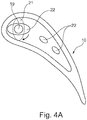
- a bayonet connection can also be used as part of the locking mechanism (see Figure 4A ) be used.
- FIG 4A a cross-section through an embodiment of the rotor blade 10 with an impingement cooling device 1 is shown, the locking connection 19 here having an elliptical cross-section.
- the locking connection 19 By rotating in the direction of the arrow - in the sense of a bayonet connection - this can be brought into positive engagement with an elliptical receptacle 21 for the locking connector 1.
- the receptacle 21 is arranged in the shroud, not shown here, of the rotor blade 10.
- the locked impingement cooling device 1 can then be soldered to the tip S of the rotor blade 10 at the connection points 22.
- the soldering points can have brazing inserts for closing the cooling channels 13A, 13B.
- FIG 4B a cross section through a further embodiment of the rotor blade 10 is shown.
- the impingement cooling device 1 is arranged in the first cooling channel 13A.
- the impingement cooling openings 2 from which the cooling medium L exits are optimally aligned due to the storage via the upper connection 18 by means of the locking connector 19, so that the cooling medium L does not hit the film cooling openings 12 in the wall of the rotor blade 10, but the surface to be cooled 20 on the inside of the leading edge channel.
- the cooling medium L emerges from the film cooling openings 12 after the impingement cooling.
- Fig. 5 an axonometric representation of an embodiment of an impingement cooling device 1 is shown.
- the locking connector 19 at the upper end is used to connect the impingement cooling device 1 to the upper part of the rotor blade 10 (see Fig. 2 ).
- the lower side of the locking connector 19 has a conical projection which engages in the here circular cross section of the impact cooling device 1.
- the upper side of the locking stub 19 has the form-fitting connection means, for example via the square or the bayonet connection.
- guide elements 4 pointing radially outward are arranged, which can produce good positioning within the cooling channel 13A.
- three guide elements 4 (for example as a rib) can be arranged on the outside of the impingement cooling device 1, each offset by 120 °. Additionally or alternatively, the guide elements 4 can also be arranged on the inside of the cooling channel 13A.
Landscapes
- Engineering & Computer Science (AREA)
- Mechanical Engineering (AREA)
- General Engineering & Computer Science (AREA)
- Turbine Rotor Nozzle Sealing (AREA)
Claims (14)
- Aube rotorique (10) pour une turbomachine (100), comprenant une plate-forme d'aube rotorique (16), une pointe (S) de l'aube rotorique (10) et un dispositif de refroidissement pour refroidir une surface (20) à l'intérieur de l'aube rotorique (10) au moyen d'un agent réfrigérant (L), l'aube rotorique (10) présentant un dispositif de refroidissement par impact (1) qui comprend une pluralité d'orifices de refroidissement par impact (2) pour dévier l'agent réfrigérant (L) coulant à l'intérieur du dispositif de refroidissement par impact (1) sur la surface (20) à refroidir au moyen du refroidissement par impact à l'intérieur de l'aube rotorique (10), la surface (20) étant située à l'extérieur du dispositif de refroidissement par impact (1), de sorte que la surface (20) peut être refroidie au moyen d'un refroidissement par impact par l'agent réfrigérant (L) sortant des orifices de refroidissement par impact (2), le dispositif de refroidissement par impact (1) étant monté mobile par rapport à l'aube rotorique (10),
caractérisée
en ce que le logement du dispositif de refroidissement par impact (1) au niveau d'un raccordement inférieur (17) au niveau de la plate-forme d'aube rotorique (16) est réalisé de manière axialement coulissante par un ajustement avec jeu ou un raccordement par palier lisse, et
en ce que le raccordement du dispositif de refroidissement par impact (1) présente à la pointe (S) de l'aube rotorique (10) une complémentarité de forme comme dispositif anti-rotation par un raccordement carré ou sous forme de raccordement à baïonnette. - Aube rotorique selon la revendication 1, caractérisée en ce que le dispositif de refroidissement par impact (1) est disposé au moins en partie en parallèle à la surface (20) à l'intérieur de l'aube rotorique (10) de sorte que l'agent réfrigérant (L) sortant heurte la surface (20) de manière perpendiculaire ou substantiellement perpendiculaire.
- Aube rotorique selon la revendication 1 ou 2, caractérisée en ce que le dispositif de refroidissement par impact (1) est réalisé au moins en partie sous forme de cylindre creux.
- Aube rotorique selon la revendication 3, caractérisée en ce que la section transversale cylindrique du dispositif de refroidissement par impact (1) est circulaire, elliptique, carrée ou polygonale.
- Aube rotorique selon au moins l'une des revendications précédentes, caractérisée en ce que le dispositif de refroidissement par impact (1) s'étend du raccordement inférieur (17) au niveau d'une plate-forme d'aube rotorique (16) jusqu'à la pointe (S) de l'aube rotorique (10).
- Aube rotorique selon au moins l'une des revendications précédentes, caractérisée en ce que le raccordement du dispositif de refroidissement par impact (1) avec la pointe (S) de l'aube rotorique (10) est réalisé de manière centrée.
- Aube rotorique selon au moins l'une des revendications précédentes, caractérisée en ce que le raccordement du dispositif de refroidissement par impact (1) avec la pointe (S) de l'aube rotorique (10) présente une liaison par brasage ou une liaison par soudage.
- Aube rotorique selon la revendication 7, caractérisée en ce que le raccordement du dispositif de refroidissement par impact (1) avec la pointe (S) de l'aube rotorique (10) présente une liaison par brasage ou une liaison par soudage entre un raccord de blocage (19) et la pointe (S) .
- Aube rotorique selon au moins l'une des revendications précédentes, caractérisée en ce que les orifices de refroidissement par impact (2) sont disposés le long de l'axe longitudinal du dispositif de refroidissement par impact (1).
- Aube rotorique selon au moins l'une des revendications précédentes, caractérisée en ce que la densité des orifices de refroidissement par impact (2) dans le dispositif de refroidissement par impact (1) à la pointe de l'aube rotorique (10) est supérieure au moins pour une zone partielle à celle dans d'autres zones du dispositif de refroidissement par impact (1).
- Aube rotorique selon au moins l'une des revendications précédentes, caractérisée en ce que les orifices de refroidissement par impact (2) du dispositif de refroidissement par impact (1) peuvent être orientés de manière ciblée sur une zone de la surface (20) à refroidir.
- Aube rotorique selon au moins l'une des revendications précédentes, caractérisée en ce que le dispositif de refroidissement par impact (1) présente un compensateur thermique élastique (3) sous la forme d'un soufflet à la base (B) de l'aube rotorique (10).
- Aube rotorique selon au moins l'une des revendications précédentes, caractérisée en ce que le dispositif de refroidissement par impact (1) présente sur la face extérieure et/ou le canal de refroidissement (13A) présente sur la face intérieure au moins un élément de guidage latéral (4) pour guider le dispositif de refroidissement par impact (1), et/ou en ce que les orifices de refroidissement par impact (2) du dispositif de refroidissement par impact (1) présentent un effet d'étranglement.
- Procédé d'assemblage d'une aube rotorique (10) selon au moins l'une des revendications précédentes, dans lequela) une aube rotorique (10) est prévue,b) un dispositif de refroidissement par impact (1) pouvant être traversé par un agent réfrigérant (L) et doté d'une pluralité d'orifices de refroidissement par impact (2) pour dévier l'agent réfrigérant (L) circulant à l'intérieur du dispositif de refroidissement par impact (1) sur une surface (20) située à l'extérieur du dispositif de refroidissement par impact (1) est inséré dans un canal de refroidissement (13A) à l'intérieur de l'aube rotorique (10), et ensuitec) le dispositif de refroidissement par impact (1) est monté sur un raccordement inférieur (17) de manière mobile par rapport à l'aube rotorique (10),caractérisé
en ce que le logement du dispositif de refroidissement par impact (1) est réalisé au niveau du raccordement inférieur (17) au niveau de la plate-forme d'aube rotorique (16) de manière axialement coulissante par un ajustement avec jeu ou un raccordement par palier lisse, et
en ce que le raccordement du dispositif de refroidissement par impact (1) présente à la pointe (S) de l'aube rotorique (10) une complémentarité de forme comme dispositif anti-rotation par un raccordement carré ou sous forme de raccordement à baïonnette.
Applications Claiming Priority (1)
| Application Number | Priority Date | Filing Date | Title |
|---|---|---|---|
| DE102016216858.4A DE102016216858A1 (de) | 2016-09-06 | 2016-09-06 | Laufschaufel für eine Turbomaschine und Verfahren für den Zusammenbau einer Laufschaufel für eine Turbomaschine |
Publications (2)
| Publication Number | Publication Date |
|---|---|
| EP3293356A1 EP3293356A1 (fr) | 2018-03-14 |
| EP3293356B1 true EP3293356B1 (fr) | 2021-03-03 |
Family
ID=59761839
Family Applications (1)
| Application Number | Title | Priority Date | Filing Date |
|---|---|---|---|
| EP17189024.7A Active EP3293356B1 (fr) | 2016-09-06 | 2017-09-01 | Aube rotorique pour turbomachine comprenant une tôle de refroidissement par impact mobile et procédé d'assemblage correspondant |
Country Status (3)
| Country | Link |
|---|---|
| US (1) | US10781699B2 (fr) |
| EP (1) | EP3293356B1 (fr) |
| DE (1) | DE102016216858A1 (fr) |
Families Citing this family (1)
| Publication number | Priority date | Publication date | Assignee | Title |
|---|---|---|---|---|
| FR3067389B1 (fr) * | 2017-04-10 | 2021-10-29 | Safran | Aube de turbine presentant une structure amelioree |
Citations (1)
| Publication number | Priority date | Publication date | Assignee | Title |
|---|---|---|---|---|
| DE602004002004T2 (de) * | 2003-02-18 | 2007-04-19 | Snecma | Mit verringertem Kühlluftdurchstrom gekühlte Turbinenschaufel |
Family Cites Families (20)
| Publication number | Priority date | Publication date | Assignee | Title |
|---|---|---|---|---|
| US3628885A (en) * | 1969-10-01 | 1971-12-21 | Gen Electric | Fluid-cooled airfoil |
| US3846041A (en) | 1972-10-31 | 1974-11-05 | Avco Corp | Impingement cooled turbine blades and method of making same |
| US4314794A (en) | 1979-10-25 | 1982-02-09 | Westinghouse Electric Corp. | Transpiration cooled blade for a gas turbine engine |
| DE3110098C2 (de) * | 1981-03-16 | 1983-03-17 | MTU Motoren- und Turbinen-Union München GmbH, 8000 München | Turbinenleitschaufel für Gasturbinentriebwerke |
| US5203873A (en) * | 1991-08-29 | 1993-04-20 | General Electric Company | Turbine blade impingement baffle |
| US5207556A (en) * | 1992-04-27 | 1993-05-04 | General Electric Company | Airfoil having multi-passage baffle |
| US5387085A (en) * | 1994-01-07 | 1995-02-07 | General Electric Company | Turbine blade composite cooling circuit |
| US6193465B1 (en) * | 1998-09-28 | 2001-02-27 | General Electric Company | Trapped insert turbine airfoil |
| US6453557B1 (en) * | 2000-04-11 | 2002-09-24 | General Electric Company | Method of joining a vane cavity insert to a nozzle segment of a gas turbine |
| US6382906B1 (en) * | 2000-06-16 | 2002-05-07 | General Electric Company | Floating spoolie cup impingement baffle |
| EP1191189A1 (fr) * | 2000-09-26 | 2002-03-27 | Siemens Aktiengesellschaft | Aube de turbine à gaz |
| EP1589192A1 (fr) * | 2004-04-20 | 2005-10-26 | Siemens Aktiengesellschaft | Aube de turbine avec noyau de refroidissement par impact |
| FR2899271B1 (fr) * | 2006-03-29 | 2008-05-30 | Snecma Sa | Ensemble d'une aube et d'une chemise de refroidissement, distributeur de turbomachine comportant l'ensemble, turbomachine, procede de montage et de reparation de l'ensemble |
| US8182223B2 (en) | 2009-02-27 | 2012-05-22 | General Electric Company | Turbine blade cooling |
| EP2573325A1 (fr) * | 2011-09-23 | 2013-03-27 | Siemens Aktiengesellschaft | Refroidissement par projection d'aubes ou pales de turbine |
| US9670797B2 (en) | 2012-09-28 | 2017-06-06 | United Technologies Corporation | Modulated turbine vane cooling |
| EP2990607A1 (fr) | 2014-08-28 | 2016-03-02 | Siemens Aktiengesellschaft | Concept de refroidissement pour aubes ou pales de turbine |
| GB201417476D0 (en) | 2014-10-03 | 2014-11-19 | Rolls Royce Plc | Internal cooling of engine components |
| US10060272B2 (en) * | 2015-01-30 | 2018-08-28 | Rolls-Royce Corporation | Turbine vane with load shield |
| DE102015111746A1 (de) | 2015-07-20 | 2017-01-26 | Rolls-Royce Deutschland Ltd & Co Kg | Gekühltes Turbinenlaufrad, insbesondere für ein Flugtriebwerk |
-
2016
- 2016-09-06 DE DE102016216858.4A patent/DE102016216858A1/de not_active Withdrawn
-
2017
- 2017-09-01 EP EP17189024.7A patent/EP3293356B1/fr active Active
- 2017-09-05 US US15/695,422 patent/US10781699B2/en active Active
Patent Citations (1)
| Publication number | Priority date | Publication date | Assignee | Title |
|---|---|---|---|---|
| DE602004002004T2 (de) * | 2003-02-18 | 2007-04-19 | Snecma | Mit verringertem Kühlluftdurchstrom gekühlte Turbinenschaufel |
Also Published As
| Publication number | Publication date |
|---|---|
| DE102016216858A1 (de) | 2018-03-08 |
| EP3293356A1 (fr) | 2018-03-14 |
| US20180066526A1 (en) | 2018-03-08 |
| US10781699B2 (en) | 2020-09-22 |
Similar Documents
| Publication | Publication Date | Title |
|---|---|---|
| EP1834066B1 (fr) | Aube de turbine pour turbine a gaz, utilisation d'une aube de turbine et procede de refroidissement d'une aube de turbine | |
| DE10059997B4 (de) | Kühlbare Schaufel für eine Gasturbinenkomponente | |
| EP3183497B1 (fr) | Élément formant bouclier thermique et procédé de fabrication de celui-ci | |
| EP1512489B1 (fr) | Aube pour turbine | |
| DE10064265A1 (de) | Vorrichtung und Verfahren zur Kühlung einer Plattform einer Turbinenschaufel | |
| DE102008055522A1 (de) | Divergente Turbinendüse | |
| EP1904717B1 (fr) | Element de carter conducteur de gaz chaud, enveloppe de protection d'arbre et systeme de turbine a gaz | |
| EP1757773A1 (fr) | Aube creuse de turbine | |
| CH707831A2 (de) | Heissgaspfadbauteil für Turbinensystem. | |
| EP2084368B1 (fr) | Aube de turbine | |
| EP3336313A1 (fr) | Ensemble d'aube mobile pour turbines d'une turbine turbine à gaz et procédé de fourniture d'air sceau dans un ensemble d'aube mobile pour turbines | |
| WO2014139738A1 (fr) | Brûleur à jet de gaz comportant un canal de refroidissement dans la plaque de base | |
| EP1905950A1 (fr) | Aube de turbine | |
| EP3293356B1 (fr) | Aube rotorique pour turbomachine comprenant une tôle de refroidissement par impact mobile et procédé d'assemblage correspondant | |
| EP3473808B1 (fr) | Pale d'aube pour une aube mobile de turbine à refroidissement intérieur ainsi que procédé de fabrication d'une telle pale | |
| DE60201325T2 (de) | Hochdruck-Turbinenschaufel mit gekühlter Abströmkante | |
| EP2347100B1 (fr) | Turbine à gaz avec insert de refroidissement | |
| EP2601382B1 (fr) | Circuit d'arrêt de turbines à vapeur pour arrêter la vapeur humide | |
| EP1731715A1 (fr) | Transition d'une chambre de combustion à une turbine | |
| EP3109520B1 (fr) | Support d'étanchéité, stator et turbomachine | |
| EP1910649B1 (fr) | Dispositif de controle actif des jeux pour une turbomachine | |
| EP1914382B1 (fr) | Procédé de réparation d'une aube de turbine | |
| DE10214624C1 (de) | Vorrichtung zur Abdichtung in Turbomaschinen | |
| WO2008025583A1 (fr) | Procédé de refroidissement d'aubes de turbine d'une couronne d'aubes et segment d'aubes de turbine destiné à une couronne d'aubes comportant au moins deux pales profilées aérodynamiquement | |
| WO2008022830A1 (fr) | aube de turbine à gaz à plate-forme refroidie |
Legal Events
| Date | Code | Title | Description |
|---|---|---|---|
| PUAI | Public reference made under article 153(3) epc to a published international application that has entered the european phase |
Free format text: ORIGINAL CODE: 0009012 |
|
| STAA | Information on the status of an ep patent application or granted ep patent |
Free format text: STATUS: THE APPLICATION HAS BEEN PUBLISHED |
|
| AK | Designated contracting states |
Kind code of ref document: A1 Designated state(s): AL AT BE BG CH CY CZ DE DK EE ES FI FR GB GR HR HU IE IS IT LI LT LU LV MC MK MT NL NO PL PT RO RS SE SI SK SM TR |
|
| AX | Request for extension of the european patent |
Extension state: BA ME |
|
| STAA | Information on the status of an ep patent application or granted ep patent |
Free format text: STATUS: REQUEST FOR EXAMINATION WAS MADE |
|
| 17P | Request for examination filed |
Effective date: 20180831 |
|
| RBV | Designated contracting states (corrected) |
Designated state(s): AL AT BE BG CH CY CZ DE DK EE ES FI FR GB GR HR HU IE IS IT LI LT LU LV MC MK MT NL NO PL PT RO RS SE SI SK SM TR |
|
| STAA | Information on the status of an ep patent application or granted ep patent |
Free format text: STATUS: EXAMINATION IS IN PROGRESS |
|
| 17Q | First examination report despatched |
Effective date: 20190724 |
|
| GRAP | Despatch of communication of intention to grant a patent |
Free format text: ORIGINAL CODE: EPIDOSNIGR1 |
|
| STAA | Information on the status of an ep patent application or granted ep patent |
Free format text: STATUS: GRANT OF PATENT IS INTENDED |
|
| INTG | Intention to grant announced |
Effective date: 20200918 |
|
| RIN1 | Information on inventor provided before grant (corrected) |
Inventor name: NEGULESCU, DIMITRIE |
|
| GRAS | Grant fee paid |
Free format text: ORIGINAL CODE: EPIDOSNIGR3 |
|
| STAA | Information on the status of an ep patent application or granted ep patent |
Free format text: STATUS: GRANT OF PATENT IS INTENDED |
|
| GRAA | (expected) grant |
Free format text: ORIGINAL CODE: 0009210 |
|
| STAA | Information on the status of an ep patent application or granted ep patent |
Free format text: STATUS: THE PATENT HAS BEEN GRANTED |
|
| AK | Designated contracting states |
Kind code of ref document: B1 Designated state(s): AL AT BE BG CH CY CZ DE DK EE ES FI FR GB GR HR HU IE IS IT LI LT LU LV MC MK MT NL NO PL PT RO RS SE SI SK SM TR |
|
| REG | Reference to a national code |
Ref country code: GB Ref legal event code: FG4D Free format text: NOT ENGLISH |
|
| REG | Reference to a national code |
Ref country code: AT Ref legal event code: REF Ref document number: 1367401 Country of ref document: AT Kind code of ref document: T Effective date: 20210315 Ref country code: CH Ref legal event code: EP |
|
| REG | Reference to a national code |
Ref country code: DE Ref legal event code: R096 Ref document number: 502017009546 Country of ref document: DE |
|
| REG | Reference to a national code |
Ref country code: IE Ref legal event code: FG4D Free format text: LANGUAGE OF EP DOCUMENT: GERMAN |
|
| REG | Reference to a national code |
Ref country code: LT Ref legal event code: MG9D |
|
| PG25 | Lapsed in a contracting state [announced via postgrant information from national office to epo] |
Ref country code: HR Free format text: LAPSE BECAUSE OF FAILURE TO SUBMIT A TRANSLATION OF THE DESCRIPTION OR TO PAY THE FEE WITHIN THE PRESCRIBED TIME-LIMIT Effective date: 20210303 Ref country code: GR Free format text: LAPSE BECAUSE OF FAILURE TO SUBMIT A TRANSLATION OF THE DESCRIPTION OR TO PAY THE FEE WITHIN THE PRESCRIBED TIME-LIMIT Effective date: 20210604 Ref country code: FI Free format text: LAPSE BECAUSE OF FAILURE TO SUBMIT A TRANSLATION OF THE DESCRIPTION OR TO PAY THE FEE WITHIN THE PRESCRIBED TIME-LIMIT Effective date: 20210303 Ref country code: NO Free format text: LAPSE BECAUSE OF FAILURE TO SUBMIT A TRANSLATION OF THE DESCRIPTION OR TO PAY THE FEE WITHIN THE PRESCRIBED TIME-LIMIT Effective date: 20210603 Ref country code: BG Free format text: LAPSE BECAUSE OF FAILURE TO SUBMIT A TRANSLATION OF THE DESCRIPTION OR TO PAY THE FEE WITHIN THE PRESCRIBED TIME-LIMIT Effective date: 20210603 Ref country code: LT Free format text: LAPSE BECAUSE OF FAILURE TO SUBMIT A TRANSLATION OF THE DESCRIPTION OR TO PAY THE FEE WITHIN THE PRESCRIBED TIME-LIMIT Effective date: 20210303 |
|
| REG | Reference to a national code |
Ref country code: NL Ref legal event code: MP Effective date: 20210303 |
|
| PG25 | Lapsed in a contracting state [announced via postgrant information from national office to epo] |
Ref country code: SE Free format text: LAPSE BECAUSE OF FAILURE TO SUBMIT A TRANSLATION OF THE DESCRIPTION OR TO PAY THE FEE WITHIN THE PRESCRIBED TIME-LIMIT Effective date: 20210303 Ref country code: RS Free format text: LAPSE BECAUSE OF FAILURE TO SUBMIT A TRANSLATION OF THE DESCRIPTION OR TO PAY THE FEE WITHIN THE PRESCRIBED TIME-LIMIT Effective date: 20210303 Ref country code: LV Free format text: LAPSE BECAUSE OF FAILURE TO SUBMIT A TRANSLATION OF THE DESCRIPTION OR TO PAY THE FEE WITHIN THE PRESCRIBED TIME-LIMIT Effective date: 20210303 Ref country code: PL Free format text: LAPSE BECAUSE OF FAILURE TO SUBMIT A TRANSLATION OF THE DESCRIPTION OR TO PAY THE FEE WITHIN THE PRESCRIBED TIME-LIMIT Effective date: 20210303 |
|
| PG25 | Lapsed in a contracting state [announced via postgrant information from national office to epo] |
Ref country code: NL Free format text: LAPSE BECAUSE OF FAILURE TO SUBMIT A TRANSLATION OF THE DESCRIPTION OR TO PAY THE FEE WITHIN THE PRESCRIBED TIME-LIMIT Effective date: 20210303 |
|
| PG25 | Lapsed in a contracting state [announced via postgrant information from national office to epo] |
Ref country code: EE Free format text: LAPSE BECAUSE OF FAILURE TO SUBMIT A TRANSLATION OF THE DESCRIPTION OR TO PAY THE FEE WITHIN THE PRESCRIBED TIME-LIMIT Effective date: 20210303 Ref country code: CZ Free format text: LAPSE BECAUSE OF FAILURE TO SUBMIT A TRANSLATION OF THE DESCRIPTION OR TO PAY THE FEE WITHIN THE PRESCRIBED TIME-LIMIT Effective date: 20210303 Ref country code: SM Free format text: LAPSE BECAUSE OF FAILURE TO SUBMIT A TRANSLATION OF THE DESCRIPTION OR TO PAY THE FEE WITHIN THE PRESCRIBED TIME-LIMIT Effective date: 20210303 |
|
| PG25 | Lapsed in a contracting state [announced via postgrant information from national office to epo] |
Ref country code: IS Free format text: LAPSE BECAUSE OF FAILURE TO SUBMIT A TRANSLATION OF THE DESCRIPTION OR TO PAY THE FEE WITHIN THE PRESCRIBED TIME-LIMIT Effective date: 20210703 Ref country code: PT Free format text: LAPSE BECAUSE OF FAILURE TO SUBMIT A TRANSLATION OF THE DESCRIPTION OR TO PAY THE FEE WITHIN THE PRESCRIBED TIME-LIMIT Effective date: 20210705 Ref country code: RO Free format text: LAPSE BECAUSE OF FAILURE TO SUBMIT A TRANSLATION OF THE DESCRIPTION OR TO PAY THE FEE WITHIN THE PRESCRIBED TIME-LIMIT Effective date: 20210303 Ref country code: SK Free format text: LAPSE BECAUSE OF FAILURE TO SUBMIT A TRANSLATION OF THE DESCRIPTION OR TO PAY THE FEE WITHIN THE PRESCRIBED TIME-LIMIT Effective date: 20210303 |
|
| REG | Reference to a national code |
Ref country code: DE Ref legal event code: R097 Ref document number: 502017009546 Country of ref document: DE |
|
| PLBE | No opposition filed within time limit |
Free format text: ORIGINAL CODE: 0009261 |
|
| STAA | Information on the status of an ep patent application or granted ep patent |
Free format text: STATUS: NO OPPOSITION FILED WITHIN TIME LIMIT |
|
| PG25 | Lapsed in a contracting state [announced via postgrant information from national office to epo] |
Ref country code: DK Free format text: LAPSE BECAUSE OF FAILURE TO SUBMIT A TRANSLATION OF THE DESCRIPTION OR TO PAY THE FEE WITHIN THE PRESCRIBED TIME-LIMIT Effective date: 20210303 Ref country code: AL Free format text: LAPSE BECAUSE OF FAILURE TO SUBMIT A TRANSLATION OF THE DESCRIPTION OR TO PAY THE FEE WITHIN THE PRESCRIBED TIME-LIMIT Effective date: 20210303 Ref country code: ES Free format text: LAPSE BECAUSE OF FAILURE TO SUBMIT A TRANSLATION OF THE DESCRIPTION OR TO PAY THE FEE WITHIN THE PRESCRIBED TIME-LIMIT Effective date: 20210303 |
|
| 26N | No opposition filed |
Effective date: 20211206 |
|
| PG25 | Lapsed in a contracting state [announced via postgrant information from national office to epo] |
Ref country code: SI Free format text: LAPSE BECAUSE OF FAILURE TO SUBMIT A TRANSLATION OF THE DESCRIPTION OR TO PAY THE FEE WITHIN THE PRESCRIBED TIME-LIMIT Effective date: 20210303 |
|
| PG25 | Lapsed in a contracting state [announced via postgrant information from national office to epo] |
Ref country code: IT Free format text: LAPSE BECAUSE OF FAILURE TO SUBMIT A TRANSLATION OF THE DESCRIPTION OR TO PAY THE FEE WITHIN THE PRESCRIBED TIME-LIMIT Effective date: 20210303 |
|
| REG | Reference to a national code |
Ref country code: CH Ref legal event code: PL |
|
| REG | Reference to a national code |
Ref country code: BE Ref legal event code: MM Effective date: 20210930 |
|
| GBPC | Gb: european patent ceased through non-payment of renewal fee |
Effective date: 20210901 |
|
| PG25 | Lapsed in a contracting state [announced via postgrant information from national office to epo] |
Ref country code: IS Free format text: LAPSE BECAUSE OF FAILURE TO SUBMIT A TRANSLATION OF THE DESCRIPTION OR TO PAY THE FEE WITHIN THE PRESCRIBED TIME-LIMIT Effective date: 20210703 Ref country code: MC Free format text: LAPSE BECAUSE OF FAILURE TO SUBMIT A TRANSLATION OF THE DESCRIPTION OR TO PAY THE FEE WITHIN THE PRESCRIBED TIME-LIMIT Effective date: 20210303 |
|
| PG25 | Lapsed in a contracting state [announced via postgrant information from national office to epo] |
Ref country code: LU Free format text: LAPSE BECAUSE OF NON-PAYMENT OF DUE FEES Effective date: 20210901 Ref country code: IE Free format text: LAPSE BECAUSE OF NON-PAYMENT OF DUE FEES Effective date: 20210901 Ref country code: GB Free format text: LAPSE BECAUSE OF NON-PAYMENT OF DUE FEES Effective date: 20210901 Ref country code: BE Free format text: LAPSE BECAUSE OF NON-PAYMENT OF DUE FEES Effective date: 20210930 |
|
| PG25 | Lapsed in a contracting state [announced via postgrant information from national office to epo] |
Ref country code: LI Free format text: LAPSE BECAUSE OF NON-PAYMENT OF DUE FEES Effective date: 20210930 Ref country code: CH Free format text: LAPSE BECAUSE OF NON-PAYMENT OF DUE FEES Effective date: 20210930 |
|
| PG25 | Lapsed in a contracting state [announced via postgrant information from national office to epo] |
Ref country code: HU Free format text: LAPSE BECAUSE OF FAILURE TO SUBMIT A TRANSLATION OF THE DESCRIPTION OR TO PAY THE FEE WITHIN THE PRESCRIBED TIME-LIMIT; INVALID AB INITIO Effective date: 20170901 |
|
| PG25 | Lapsed in a contracting state [announced via postgrant information from national office to epo] |
Ref country code: CY Free format text: LAPSE BECAUSE OF FAILURE TO SUBMIT A TRANSLATION OF THE DESCRIPTION OR TO PAY THE FEE WITHIN THE PRESCRIBED TIME-LIMIT Effective date: 20210303 |
|
| P01 | Opt-out of the competence of the unified patent court (upc) registered |
Effective date: 20230528 |
|
| REG | Reference to a national code |
Ref country code: AT Ref legal event code: MM01 Ref document number: 1367401 Country of ref document: AT Kind code of ref document: T Effective date: 20220901 |
|
| PGFP | Annual fee paid to national office [announced via postgrant information from national office to epo] |
Ref country code: FR Payment date: 20230926 Year of fee payment: 7 Ref country code: DE Payment date: 20230928 Year of fee payment: 7 |
|
| PG25 | Lapsed in a contracting state [announced via postgrant information from national office to epo] |
Ref country code: AT Free format text: LAPSE BECAUSE OF NON-PAYMENT OF DUE FEES Effective date: 20220901 |
|
| PG25 | Lapsed in a contracting state [announced via postgrant information from national office to epo] |
Ref country code: MK Free format text: LAPSE BECAUSE OF FAILURE TO SUBMIT A TRANSLATION OF THE DESCRIPTION OR TO PAY THE FEE WITHIN THE PRESCRIBED TIME-LIMIT Effective date: 20210303 |