EP3292805A1 - Stützfuss für eine küchenmaschinen-ergänzungskomponente und küchenmaschinen-ergänzungskomponente mit stützfuss - Google Patents
Stützfuss für eine küchenmaschinen-ergänzungskomponente und küchenmaschinen-ergänzungskomponente mit stützfuss Download PDFInfo
- Publication number
- EP3292805A1 EP3292805A1 EP17186256.8A EP17186256A EP3292805A1 EP 3292805 A1 EP3292805 A1 EP 3292805A1 EP 17186256 A EP17186256 A EP 17186256A EP 3292805 A1 EP3292805 A1 EP 3292805A1
- Authority
- EP
- European Patent Office
- Prior art keywords
- component
- support leg
- food processor
- elements
- support
- Prior art date
- Legal status (The legal status is an assumption and is not a legal conclusion. Google has not performed a legal analysis and makes no representation as to the accuracy of the status listed.)
- Granted
Links
Images
Classifications
-
- A—HUMAN NECESSITIES
- A47—FURNITURE; DOMESTIC ARTICLES OR APPLIANCES; COFFEE MILLS; SPICE MILLS; SUCTION CLEANERS IN GENERAL
- A47J—KITCHEN EQUIPMENT; COFFEE MILLS; SPICE MILLS; APPARATUS FOR MAKING BEVERAGES
- A47J43/00—Implements for preparing or holding food, not provided for in other groups of this subclass
- A47J43/04—Machines for domestic use not covered elsewhere, e.g. for grinding, mixing, stirring, kneading, emulsifying, whipping or beating foodstuffs, e.g. power-driven
- A47J43/07—Parts or details, e.g. mixing tools, whipping tools
-
- A—HUMAN NECESSITIES
- A47—FURNITURE; DOMESTIC ARTICLES OR APPLIANCES; COFFEE MILLS; SPICE MILLS; SUCTION CLEANERS IN GENERAL
- A47J—KITCHEN EQUIPMENT; COFFEE MILLS; SPICE MILLS; APPARATUS FOR MAKING BEVERAGES
- A47J47/00—Kitchen containers, stands or the like, not provided for in other groups of this subclass; Cutting-boards, e.g. for bread
- A47J47/16—Stands, or holders for kitchen articles
-
- F—MECHANICAL ENGINEERING; LIGHTING; HEATING; WEAPONS; BLASTING
- F16—ENGINEERING ELEMENTS AND UNITS; GENERAL MEASURES FOR PRODUCING AND MAINTAINING EFFECTIVE FUNCTIONING OF MACHINES OR INSTALLATIONS; THERMAL INSULATION IN GENERAL
- F16M—FRAMES, CASINGS OR BEDS OF ENGINES, MACHINES OR APPARATUS, NOT SPECIFIC TO ENGINES, MACHINES OR APPARATUS PROVIDED FOR ELSEWHERE; STANDS; SUPPORTS
- F16M7/00—Details of attaching or adjusting engine beds, frames, or supporting-legs on foundation or base; Attaching non-moving engine parts, e.g. cylinder blocks
Definitions
- the present invention relates to a length-adjustable support leg for a food processor supplemental component and a food processor supplemental component with a support leg.
- Food processors usually offer a variety of functionalities. For example, they can be used to shred vegetables, to grind nuts, to whisk dough, as a juicer and / or as a meat grinder, just to name a few.
- kitchen machines may be expandable with respective food processor add-on components which may then comprise specific elements, for example a special hopper, a specially designed receptacle and / or at least one special comminution tool suitable for each supplemented functionality. suitable.
- Such supplemental components are generally attached to at least one intended connection region of the food processor and possibly connected to the motor.
- the supplemental components In order to withstand mechanical stresses during use, the supplemental components generally need to be supported at one or more points.
- the supplementary components may have at least one integrated or separate supporting foot to be fastened.
- connection area for the supplementary components depending on the type of food processor at different positions in particular (when intended for use alignment of the food processor) can be arranged at different heights on a substrate, the supplemental component and / or its at least one support leg suitable for Type of food processor provided and selected by the user accordingly.
- Support feet must be made to suit different types of kitchen appliances and marked accordingly.
- the supplemental component with the at least one support leg according to conventional technology is only suitable for the respective type of kitchen appliance, so that a user (for example, with a changed need or after an irreparable defect of the food processor) can not change to another type, without also replace the supplementary component.
- a suitable length can also depend on the supplementary component itself (namely on a respective required support height which the support leg must reach), so that for different supplementary components Different support feet may be necessary.
- the object of the present invention is to provide a technique with which the mentioned disadvantages can be overcome and which, in particular, increases flexibility of use for kitchen appliance accessories.
- An inventive support leg for a food processor supplementary component comprises at least two interconnected elements.
- a first of these elements has a component attachment that attaches to or is adapted to be attached to (for example, attached to) the food processor add-on component.
- a second of said elements has an attachment end for placement on a substrate (e.g., a table or kitchen worktop). The distance between the component attachment and the attachment end is adjustable (by a user).
- the support leg can be adapted to different conditions and is particularly suitable for use for different types of food processors and / or food processor supplemental components.
- An inventive support leg is thus can be used flexibly, and the production of food processor supplemental components is simplified due to the universal usability of the support leg.
- the first element may be formed, for example, rod, tube or rail-like, and the same applies to the second element.
- the at least two elements are connected to each other telescopically.
- one of the elements forms a guide frame (for example, comprises a rail closed at least three longitudinal sides or a tube), in which another of the elements is partially inserted and can be pulled out or inserted to a variable extent.
- the elements can thus stabilize each other, and the support leg can be made very easily.
- the support foot in this case has a blocking device which prevents withdrawal beyond a maximum extent (and in particular releasing a connection of the at least two elements).
- the second element has an end opposite the fitting end, which is at least partially encompassed by another of the elements of the support leg (for example, the first element).
- the end of the second element which is at least partially engaged and opposite the attachment end can preferably be displaced in the interior of the further (in particular of the first element).
- the second element in such an embodiment thus has a smaller cross-section than the further or first element, so that in a proper arrangement or alignment contamination from above (in a gap between the two elements) is prevented.
- a support leg according to the invention has a fixing mechanism for fixing in each case one of at least two different selectable positions of the at least two elements relative to one another.
- the fixing mechanism may, for example, comprise a latching mechanism, which is adapted to the first and the second element in different adjustable positions relative to each other to lock or the fixing mechanism may comprise a clamping device which is adapted to clamp the first and the second element in different adjustable positions relative to each other.
- the fixing mechanism may comprise a lock, which is preferably at least partially disposed in the interior of at least one of the elements.
- a variant embodiment is advantageous in which the fixing mechanism can be operated via at least one operating element, for example at least one button.
- the fixation can for example be effected by a spring and by pressure on such a control element (the spring force against) to be solved.
- the support leg can be fixed in a suitably chosen length (ie with a selected distance from the component attachment and attachment end from each other) and from then on (until a new adjustment) be used to support the food processor supplemental component.
- the distance between the component attachment and the attachment end is continuously adjustable at least within one region.
- At least two of the elements can be connected to one another, for example, by means of a screw connection, in particular one of the elements can comprise a screw bolt and another a suitable thread into which the screw bolt can be screwed adjustably far.
- a support foot of such an embodiment is particularly flexible usable.
- it is also suitable for adaptation to an uneven surface and / or for use with a food processor (or a food processor supplemental component) with not previously known dimensions (for example, a food processor of a later developed type).
- the first element is formed monolithically with at least one housing part of the kitchen machine supplemental component, so on the housing part (which may also be the entire housing) formed;
- the housing part which may also be the entire housing
- Particularly advantageous is an embodiment in the housing part and the first element at least partially in one Injection molding methods are made of plastic. At the component approach, the support foot thus goes over into the housing part.
- connection between food processor supplemental component and support leg is particularly solid. Since this also no connection mechanism is needed, the production of food processor supplemental component and the support foot is simplified.
- an inventive support foot is designed as a separate or detachable from the kitchen machine supplement component item.
- the support foot on its component approach preferably on a support surface (on which the food processor supplemental component can be brought to rest and preferably has shape, which is adapted to a Aufliege Scheme a housing part of the kitchen machine supplement component), and / or a fastening means for attachment the support foot on a housing part of the kitchen machine supplement component.
- a fastener may e.g. a screwing device and / or a holding rail and / or a latching device.
- Such a support leg is particularly variable in use and can be used in particular for various food processor supplemental components alternatively.
- a support leg according to the invention comprises a spring mechanism which is set up to press apart the component attachment and the attachment end. In this way, the landing end can be driven away from the component hub by the spring mechanism until it sits on the ground; in the length thus achieved, the support foot can preferably be determined.
- the spring mechanism can be activated and / or deactivated, for example, by means of an operating element on the support foot.
- the distance between the component attachment and the attachment end is preferably adjustable by at least 2 cm, more preferably at least 3 cm, the difference between a maximum possible and a minimum possible length of the support leg is therefore preferably at least 2 cm, more preferably at least 3 cm.
- the length of the support leg is thus preferably variable by at least 2 cm, more preferably at least 3 cm. This ensures a flexible usability of the support foot.
- a kitchen machine supplemental component according to the invention comprises a support leg according to the invention according to one of the embodiments disclosed in this document.
- the support leg can be attached as a separate component to the food processor supplemental component (preferably releasably) or formed integrally with at least one housing part of the food processor supplemental component.
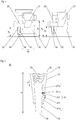
- FIG. 1 schematically two kitchen machines 10, 10 'of different types for comparison in a proper orientation on a substrate U standing shown.
- the kitchen machines 10 and 10' are each the same food processor supplemental component 20 is attached.
- the food processor supplemental component 20 is held on the two food processors in different positions relative to the ground, where they each supported by the same support leg 30 according to the invention.
- the support leg 30 comprises a first element 31 and a second element 33, which are connected to each other.
- the first element 31 comprises a component attachment 32, to which it attaches to the food processor add-on component 20.
- This component approach may be formed in a continuous material transition, so that a housing part of the kitchen machine supplemental component 20 is monolithically formed with the first element 31, or the first element can be attached as a separate component (and preferably releasably) to the food processor supplemental component 20 , preferably fastened.
- the second element 33 sets with a touchdown end 34 on the substrate U.
- the distance between the component projection 32 and the attachment end 34 is adjustable according to the invention; As is apparent from the representation of the kitchen machines 10 and 10 'in comparison, a distance H 1 has been set for supporting the kitchen machine attachment component 20 fastened to the food processor 10, whereas for supporting the food processor attached to the food processor 10' a supplemental machine component 20 H 2 was set. Due to the adjustability of the distance and thus the length of the support leg 30 can be used for both kitchen machines 10 and 10 'of the same support leg.
- An adjustable distance difference is preferably at least 2cm, more preferably at least 3cm.
- FIG. 2 is - greatly simplified - a structure of a support leg according to the invention 30 according to an exemplary embodiment of the present invention shown in cross section.
- the support leg 30 is formed as a separate component with a first element 31 and a second element 33.
- the first element 31 has on a component attachment 32 a fastening means 35, which is adapted to be connected for fastening the support foot with a suitable counter element of a food processor supplemental component.
- the first element 31 partially surrounds the second element 33; within the first element 31 so that the second element 33 is displaceable, so that a distance H of the component approach of a fitting end 34 of the support leg is variable.
- the support leg shown comprises a spring mechanism 36 with a spring which pushes away the second element from the component projection 32 with a spring force F and thus acts to increase the distance H.
- the spring force counteracts a fixing mechanism 37 which in the present case is designed as a latching mechanism and comprises an operating element 373, which in the example shown is shaped as a lever.
- a fixing mechanism 37 which in the present case is designed as a latching mechanism and comprises an operating element 373, which in the example shown is shaped as a lever.
- Whose end within the first element 31 engages in a recess 371 b and thus prevents an adjustment of the distance H.
- the second element 33 is therefore locked in the position shown relative to the first element 31.
- the detent mechanism 37 further includes a spring 372 which holds the said end of the operating member in the recess 371a. If now the control element is actuated against the force of the spring 372, the latching is released, the second element 33 can be moved relative to the first element 31 in this and the distance H of the component attachment 32 and attachment end 34 are adjusted. If there is a counterpressure exceeding the spring force F by placing the attachment end 34 on a substrate (not shown), the second element 33 will continue into the first Element 31 is pressed in and shortens the distance H, for example, until the arranged inside the first element 31 end of the control element 373 snaps into the recess 371 c (if the control element is released).
- the spring mechanism 36 further drives the second element 33 out of the first element 31, so that the distance H is increased, for example until the end of the operating element 373 disposed in the interior of the first element 31 in the recess 371a engages (again if the control is released).
- a manual adjustment of the height H may be provided, in which therefore the second element 33 is further pulled out of the first element or pressed into the first element.
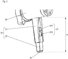
- FIG. 3 is a perspective view of a support leg 30 'according to an alternative embodiment of the present invention shown.
- the support leg 30 ' is integrally formed on a housing part of a food processor supplemental component 20, for example by means of an injection molding process; Housing part and the first element 31 of the support leg are in this case preferably at least partially made of plastic.
- the component projection 32 is formed in a continuous material transition between the housing part and the first element 31.
- the first element 31 and the second element 33 are telescopically connected to each other, in the present case, the second element can be partially pulled out of the first or pushed into the first element.
- the first and the second element could for example be variably angled against each other, for example, according to a folding rule.
- the support leg 30 'further includes a fixing mechanism 37' comprising two buttons 374 'and 375' with which a fixing mechanism (not shown) for fixing the position of the first and second members relative to each other can be released or activated.
- An inventive support leg 30, 30 'for a food processor supplementary component 20 comprises at least two interconnected elements.
- a first of the elements 31 has a component lug 32 which attaches to the food processor add-on component 20 or is adapted to be attached to the food processor add-on component.
- a second of the elements 33 has an attachment end 34 for placement on a substrate U. The distance H, H 1 , H 2 between the component attachment 32 and the attachment end 34 is adjustable.
- a food processor supplementary component 20 according to the invention comprises a support leg 30, 30 'according to the invention.
Landscapes
- Engineering & Computer Science (AREA)
- Food Science & Technology (AREA)
- Mechanical Engineering (AREA)
- Food-Manufacturing Devices (AREA)
Description
- Die vorliegende Erfindung betrifft einen längenverstellbaren Stützfuß für eine Küchenmaschinen-Ergänzungskomponente und eine Küchenmaschinen-Ergänzungskomponente mit einem Stützfuß.
- Küchenmaschinen bieten in der Regel eine Vielzahl an Funktionalitäten. So können sie beispielsweise zum Häckseln von Gemüse, zum Mahlen von Nüssen, zum Quirlen von Teig, als Saftpresse und/oder als Fleischwolf geeignet sein, um nur einige von vielen Möglichkeiten zu nennen. Für einige ihrer Funktionalitäten können Küchenmaschinen um jeweilige Küchenmaschinen-Ergänzungskomponenten erweiterbar sein, die dann spezifische Elemente aufweisen können, beispielsweise einen besonderen Einfülltrichter, einen eigens ausgebildeten Auffangbehälter und/oder mindestens ein spezielles Zerkleinerungswerkzeug, der/die sich jeweils für die jeweils ergänzte Funktionalität eignet/eignen.
- Derartige Ergänzungskomponenten werden im Allgemeinen an mindestens einem vorgesehenen Anschlussbereich der Küchenmaschine befestigt und ggf. mit deren Motor verbunden. Um mechanischen Belastungen bei der Verwendung standzuhalten, müssen die Ergänzungskomponenten in der Regel an einem oder mehreren Punkt/en abgestützt werden. Dazu können die Ergänzungskomponenten mindestens einen integrierten oder separaten, zu befestigenden Stützfuß aufweisen.
- Da nun der jeweilige Anschlussbereich für die Ergänzungskomponenten je nach Typus der Küchenmaschine an unterschiedlichen Positionen, insbesondere (bei für eine Verwendung vorgesehener Ausrichtung der Küchenmaschine) in unterschiedlichen Höhen über einem Untergrund angeordnet sein kann, muss die Ergänzungskomponente und/oder ihr mindestens einer Stützfuß passend zum Typus der Küchenmaschine bereitgestellt und vom Verwender entsprechend korrekt ausgewählt werden. Dies bedeutet neben einer hohen Fehleranfälligkeit bei der Auswahl durch den Verwender einen erhöhten Herstellungsaufwand, weil die jeweilige Ergänzungskomponenten bzw.
- Stützfüße passend zu verschiedenen Küchenmaschinentypen gefertigt und entsprechend gekennzeichnet werden müssen. Zudem ist die Ergänzungskomponente mit dem mindestens einen Stützfuß gemäß herkömmlicher Technik nur für den jeweiligen Küchenmaschinentyp geeignet, so dass ein Verwender (beispielsweise bei geändertem Bedarf oder nach einem irreparablen Defekt der Küchenmaschine) nicht auf einen anderen Typ umsteigen kann, ohne auch die Ergänzungskomponente auszutauschen. In Ausführungsvarianten, bei denen der mindestens eine Stützfuß als separates Element an der Ergänzungskomponente anzusetzen ist, kann eine geeignete Länge zudem von der Ergänzungskomponente selbst (nämlich von einer jeweils erforderlichen Stützhöhe, die der Stützfuß erreichen muss) abhängen, so dass für verschiedene Ergänzungskomponenten ggf. verschiedene Stützfüße notwendig sein können.
- Die vorliegende Erfindung hat die Aufgabe, eine Technik bereitzustellen, mit der die genannten Nachteile überwunden werden können und die insbesondere eine Einsatzflexibilität für Küchenmaschinenzubehör erhöht.
- Die Aufgabe wird gelöst von einem Stützfuß für eine Küchenmaschinen-Ergänzungskomponente gemäß Anspruch 1 und einer Küchenmaschinen-Ergänzungskomponente gemäß Anspruch 7. Vorteilhafte Ausführungsformen sind in den Unteransprüchen, der Beschreibung und den Figuren offenbart.
- Ein erfindungsgemäßer Stützfuß für eine Küchenmaschinen-Ergänzungskomponente umfasst mindestens zwei miteinander verbundene Elemente. Ein erstes dieser Elemente hat einen Komponentenansatz, der an der Küchenmaschinen-Ergänzungskomponente ansetzt oder dazu eingerichtet ist, an der Küchenmaschinen-Ergänzungskomponente angesetzt (z.B. befestigt) zu werden. Ein zweites der genannten Elemente hat ein Aufsetz-Ende zum Aufsetzen auf einem Untergrund (z.B. einer Tisch- oder Küchenarbeitsplatte). Der Abstand zwischen dem Komponentenansatz und dem Aufsetz-Ende ist dabei (von einem Verwender) verstellbar.
- Mit dem Abstand kann also eine Länge des Stützfußes eingestellt werden. So kann der Stützfuß an verschiedene Bedingungen angepasst werden und eignet sich insbesondere zur Verwendung für unterschiedliche Typen von Küchenmaschinen und/oder Küchenmaschinen-Ergänzungskomponenten. Ein erfindungsgemäßer Stützfuß ist somit flexibel einsetzbar, und die Herstellung der Küchenmaschinen-Ergänzungskomponenten ist aufgrund der universellen Verwendbarkeit des Stützfußes vereinfacht.
- Das erste Element kann beispielsweise stab-, rohr- oder schienenartig ausgebildet sein, und Analoges gilt für das zweite Element.
- Gemäß einer vorteilhaften Ausführungsform sind die mindestens zwei Elemente teleskopartig miteinander verbunden. Insbesondere ist eine Ausführungsform vorteilhaft, bei der eines der Elemente einen Führungsrahmen ausbildet (beispielsweise eine an mindestens drei Längsseiten geschlossene Schiene oder ein Rohr umfasst), in den ein anderes der Elemente teilweise eingesteckt ist und in veränderlichem Ausmaß herausgezogen bzw. eingeschoben werden kann. Die Elemente können sich so gegenseitig stabilisieren, und der Stützfuß kann besonders leicht hergestellt werden. Vorteilhafterweise weist der Stützfuß dabei eine Blockiereinrichtung auf, die ein Herausziehen über ein maximal vorgesehenes Ausmaß hinaus (und insbesondere ein Lösen einer Verbindung der mindestens zwei Elemente) verhindert.
- Vorzugsweise hat das zweite Element ein dem Aufsetz-Ende gegenüberliegendes Ende, das vom einem weiteren der Elemente des Stützfußes (beispielsweise vom ersten Element) mindestens teilweise umgriffen wird. Das derart mindestens teilweise umgriffene, dem Aufsetz-Ende gegenüberliegende Ende des zweiten Elements kann dabei vorzugsweise im Inneren des weiteren (insbesondere des ersten Elements) verschoben werden.
- Das zweite Element hat bei einer derartigen Ausführungsform somit einen kleineren Querschnitt als das weitere bzw. erste Element, so dass bei einer bestimmungsgemäßen Anordnung bzw. Ausrichtung ein Verschmutzen von oben (in einen Zwischenraum zwischen den beiden Elementen) verhindert wird.
- Gemäß einer vorteilhaften Ausführungsform weist ein erfindungsgemäßer Stützfuß einen Fixiermechanismus zum Fixieren jeweils einer von mindestens zwei verschiedenen wählbaren Stellungen der mindestens zwei Elemente relativ zueinander auf. Der Fixiermechanismus kann beispielsweise einen Rastmechanismus umfassen, der dazu eingerichtet ist, das erste und das zweite Element in verschieden einstellbaren Positionen relativ zueinander zu verrasten, oder der Fixiermechanismus kann eine Klemmvorrichtung umfassen, die dazu eingerichtet ist, das erste und das zweite Element in verschieden einstellbaren Positionen relativ zueinander zu verklemmen.
- Der Fixiermechanismus kann eine Verriegelung umfassen, die vorzugsweise mindestens teilweise im Innern mindestens eines der Elemente angeordnet ist. Vorteilhaft ist eine Ausführungsvariante, bei welcher der Fixiermechanismus über mindestens ein Bedienelement, beispielsweise wenigstens einen Knopf zu bedienen ist. Die Fixierung kann beispielsweise durch eine Feder zu bewirken und durch Druck auf ein derartiges Bedienelement (der Federkraft entgegen) zu lösen sein.
- Auf diese Weise kann der Stützfuß in einer passend gewählten Länge (also mit einem gewählten Abstand von Komponentenansatz und Aufsetz-Ende voneinander) fixiert werden und fortan (bis zu einer erneuten Verstellung) dazu verwendet werden, die Küchenmaschinen-Ergänzungskomponente abzustützen.
- Gemäß einer vorteilhaften Ausführungsform ist der Abstand zwischen dem Komponentenansatz und dem Aufsetz-Ende mindestens innerhalb eines Bereichs kontinuierlich verstellbar. Mindestens zwei der Elemente können beispielsweise mittels einer Verschraubung miteinander verbunden sein, insbesondere kann eines der Elemente einen Schraubbolzen umfassen und ein anderes ein passendes Gewinde, in das der Schraubbolzen verstellbar weit eingeschraubt werden kann.
- Ein Stützfuß einer derartigen Ausführungsform ist besonders flexibel verwendbar. Insbesondere eignet er sich auch zu Anpassung an einen unebenen Untergrund und/oder zur Verwendung mit einer Küchenmaschine (bzw. einer Küchenmaschinen-Ergänzungskomponente) mit nicht vorab bekannten Abmessungen (beispielsweise einer Küchenmaschine eines erst später entwickelten Typs).
- Gemäß einer vorteilhaften Ausführungsform eines erfindungsgemäßen Stützfußes ist das erste Element mit mindestens einem Gehäuseteil der Küchenmaschinen-Ergänzungskomponente monolithisch ausgebildet, also an das Gehäuseteil (das auch das gesamte Gehäuse sein kann) angeformt; besonders vorteilhaft ist eine Ausführungsform, bei der Gehäuseteil und erstes Element mindestens teilweise in einem Spritzgussverfahren aus Kunststoff hergestellt sind. Am Komponentenansatz geht dabei also der Stützfuß in das Gehäuseteil über.
- Bei einer derartigen Ausführungsform ist die Verbindung zwischen Küchenmaschinen-Ergänzungskomponente und Stützfuß besonders solide. Da hierfür zudem kein Verbindungsmechanismus benötigt wird, ist die Herstellung der Küchenmaschinen-Ergänzungskomponente und des Stützfußes vereinfacht.
- Gemäß einer alternativen vorteilhaften Ausführungsform ist ein erfindungsgemäßer Stützfuß als separates oder von der Küchenmaschinen-Ergänzungskomponente loszulösendes Einzelteil ausgebildet. Dabei weist der Stützfuß an seinem Komponentenansatz vorzugsweise eine Auflagefläche auf (auf der die Küchenmaschinen-Ergänzungskomponente zur Auflage gebracht werden kann und die vorzugsweise Form hat, die an einen Aufliegebereich eines Gehäuseteils der Küchenmaschinen-Ergänzungskomponente angepasst ist), und/oder ein Befestigungsmittel zur Befestigung des Stützfußes an einem Gehäuseteil der Küchenmaschinen-Ergänzungskomponente. Ein derartiges Befestigungsmittel kann z.B. eine Schraubvorrichtung und/oder eine Halteschiene und/oder eine Einrastvorrichtung umfassen.
- Ein derartiger Stützfuß ist besonders variabel einsetzbar und kann insbesondere für verschiedene Küchenmaschinen-Ergänzungskomponenten alternativ verwendet werden.
- In eine vorteilhaften Ausführungsvariante umfasst ein erfindungsgemäßer Stützfuß einen Federmechanismus, der dazu eingerichtet ist, den Komponentenansatz und das Aufsetz-Ende auseinander zu drücken. Auf diese Weise kann das Aufsetz-Ende mittels des Federmechanismus' bis zu seinem Aufsetzen auf dem Untergrund vom Komponentenansatz weg getrieben werden; in der damit erreichten Länge kann der Stützfuß vorzugsweise festgestellt werden.
- Dies ermöglicht ein besonders einfaches und präzises, bedarfsgerechtes Auseinandertreiben des Stützfußes, weil die Küchenmaschinen-Ergänzungskomponente dabei bereits in der vorgesehenen Position gehalten werden kann und sich eine benötigte Länge des Stützfußes mittels der Feder automatisch einstellt.
- Der Federmechanismus kann beispielsweise mittels eines Bedienelements am Stützfuß aktivierbar und/oder deaktivierbar sein.
- Der Abstand zwischen dem Komponentenansatz und dem Aufsetz-Ende ist vorzugsweise um mindestens 2cm, bevorzugter mindestens 3cm verstellbar, der Unterschied zwischen einer maximal möglichen und einer minimal möglichen Länge des Stützfußes beträgt also vorzugsweise wenigstens 2cm, bevorzugter wenigstens 3cm. Anders formuliert ist die Länge des Stützfußes somit vorzugsweise um mindestens 2cm, bevorzugter mindestens 3cm variierbar. Dies gewährleistet eine flexible Verwendbarkeit des Stützfußes.
- Eine erfindungsgemäße Küchenmaschinen-Ergänzungskomponente umfasst einen erfindungsgemäßen Stützfuß gemäß einer der in dieser Schrift offenbarten Ausführungsformen. Der Stützfuß kann dabei als separates Bauteil an der Küchenmaschinen-Ergänzungskomponente (vorzugsweise lösbar) befestigt oder einteilig mit mindestens einem Gehäuseteil der Küchenmaschinen-Ergänzungskomponente geformt sein.
- Im Folgenden werden bevorzugte Ausführungsbeispiele der Erfindung anhand von Zeichnungen näher erläutert. Es versteht sich, dass einzelne Elemente und Komponenten auch anders kombiniert werden können als dargestellt. Bezugszeichen für einander entsprechende Elemente sind figurenübergreifend verwendet und werden ggf. nicht für jede Figur neu beschrieben.
- Es zeigen schematisch:
- Figur 1:
- zwei Küchenmaschinen verschiedener Typen mit jeweils durch einen erfindungsgemäßen Stützfuß abgestützter Küchenmaschinen-Ergänzungskomponente;
- Figur 2:
- einen Aufbau eines erfindungsgemäßen Stützfußes gemäß einer exemplarischen Ausführungsform der vorliegenden Erfindung im Querschnitt; und
- Figur 3:
- einen erfindungsgemäßen Stützfuß gemäß einer alternativen exemplarischen Ausführungsform der vorliegenden Erfindung in perspektivischer Ansicht.
- In
Figur 1 sind schematisch zwei Küchenmaschinen 10, 10' unterschiedlicher Typen zum Vergleich in einer bestimmungsgemäßen Ausrichtung auf einem Untergrund U stehend dargestellt. An einem jeweiligen Anschlussbereich 21 bzw. 21' der Küchenmaschinen 10 bzw. 10' ist jeweils die gleiche Küchenmaschinen-Ergänzungskomponente 20 befestigt. - Die Küchenmaschinen 10 und 10' unterscheiden sich in dem Abstand h1 bzw. h2 ihres jeweiligen Anschlussbereichs 21 bzw. 21' vom Untergrund U. Dadurch wird die Küchenmaschinen-Ergänzungskomponente 20 an den beiden Küchenmaschinen in unterschiedlichen Positionen relativ zum Untergrund gehalten, wo sie jeweils durch den gleichen erfindungsgemäßen Stützfuß 30 abgestützt werden.
- Der Stützfuß 30 umfasst ein erstes Element 31 und ein zweites Element 33, die miteinander verbunden sind. Das erste Element 31 umfasst einen Komponentenansatz 32, an dem es an der Küchenmaschinen-Ergänzungskomponente 20 ansetzt. Dieser Komponentenansatz kann dabei in einem kontinuierlichen Materialübergang ausgebildet sein, so dass also ein Gehäuseteil der Küchenmaschinen-Ergänzungskomponente 20 monolithisch mit dem ersten Element 31 ausgebildet ist, oder das erste Element kann als separates Bauteil (und vorzugsweise lösbar) an der Küchenmaschinen-Ergänzungskomponente 20 angesetzt, vorzugsweise befestigt worden sein.
- Das zweite Element 33 setzt mit einem Aufsetz-Ende 34 auf dem Untergrund U auf. Der Abstand zwischen dem Komponentenansatz 32 und dem Aufsetz-Ende 34 ist dabei erfindungsgemäß verstellbar; wie sich aus der Darstellung der Küchenmaschinen 10 und 10' im Vergleich ergibt, wurde zum Abstützen der an der Küchenmaschine 10 befestigten Küchenmaschinen-Ergänzungskomponente 20 ein Abstand H1 eingestellt, wohingegen zum Abstützen der an der Küchenmaschine 10' befestigten Küchenmaschinen-Ergänzungskomponente 20 ein Abstand H2 eingestellt wurde. Aufgrund der Verstellbarkeit des Abstandes und damit der Länge des Stützfußes 30 kann für beide Küchenmaschinen 10 und 10' der gleiche Stützfuß verwendet werden.
- Eine einstellbare Abstandsdifferenz beträgt vorzugsweise mindestens 2cm, bevorzugter mindestens 3cm.
- In
Figur 2 ist - stark vereinfacht - ein Aufbau eines erfindungsgemäßen Stützfußes 30 gemäß einer exemplarischen Ausführungsform der vorliegenden Erfindung im Querschnitt dargestellt. Der Stützfuß 30 ist als ein separates Bauteil mit einem ersten Element 31 und einem zweiten Element 33 ausgebildet. Das erste Element 31 weist an einem Komponentenansatz 32 ein Befestigungsmittel 35 auf, das dazu eingerichtet ist, zur Befestigung des Stützfußes mit einem geeigneten Gegenelement einer Küchenmaschinen-Ergänzungskomponente verbunden zu werden. - Wie zu sehen ist, umgreift das erste Element 31 das zweite Element 33 teilweise; innerhalb des ersten Elements 31 ist damit das zweite Element 33 verschieblich, so dass ein Abstand H des Komponentenansatz von einem Aufsetz-Ende 34 des Stützfußes veränderlich ist.
- Dabei umfasst der gezeigte Stützfuß einen Federmechanismus 36 mit einer Feder, die mit einer Federkraft F das zweite Element vom Komponentenansatz 32 wegdrückt und so darauf hinwirkt, den Abstand H zu vergrößern.
- Der Federkraft entgegen wirkt ein Fixiermechanismus 37, der vorliegend als Rastmechanismus ausgebildet ist und ein Bedienelement 373 umfasst, das im gezeigten Beispiel als ein Hebel geformt ist. Dessen innerhalb des ersten Elements 31 liegendes Ende greift in eine Vertiefung 371 b ein und verhindert so ein Verstellen des Abstandes H. Das zweite Element 33 ist daher in der gezeigten Stellung relativ zum ersten Element 31 verrastet.
- Der Rastmechanismus 37 umfasst weiterhin eine Feder 372, die das besagte Ende des Bedienelements in der Vertiefung 371a hält. Wird nun das Bedienelement entgegen der Kraft der Feder 372 betätigt, so wird die Verrastung gelöst, das zweite Element 33 kann relativ zum ersten Element 31 in diesem verschoben und der Abstand H von Komponentenansatz 32 und Aufsetz-Ende 34 damit verstellt werden. Erfolgt dabei ein die Federkraft F übersteigender Gegendruck durch Aufsetzen des Aufsetz-Endes 34 auf einen (nicht gezeigten) Untergrund, wird das zweite Element 33 weiter in das erste Element 31 hineingedrückt und der Abstand H verkürzt, beispielsweise bis das im Innern des ersten Elements 31 angeordnete Ende des Bedienelements 373 in der Vertiefung 371 c einrastet (sofern das Bedienelement losgelassen wird).
- Erfolgt kein derartiges Aufsetzen auf den Untergrund, treibt der Federmechanismus 36 das zweite Element 33 weiter aus dem ersten Element 31 heraus, so dass der Abstand H vergrößert wird, beispielsweise bis das im Innern des ersten Elements 31 angeordnete Ende des Bedienelements 373 in der Vertiefung 371a einrastet (wiederum sofern das Bedienelement losgelassen wird).
- Alternativ zu einem Federmechanismus 36, wie er in der
Figur 2 gezeigt ist, kann ein manuelles Verstellen der Höhe H vorgesehen sein, bei dem also das zweite Element 33 aus dem ersten Element weiter herausgezogen oder in das erste Element hineingedrückt wird. - In
Figur 3 ist in perspektivischer Ansicht ein Stützfuß 30' gemäß einer alternativen Ausführungsform der vorliegenden Erfindung dargestellt. Der Stützfuß 30' ist dabei einteilig an ein Gehäuseteil einer Küchenmaschinen-Ergänzungskomponente 20 angeformt, beispielsweise mittels eines Spritzgussverfahrens; Gehäuseteil und das erste Element 31 des Stützfußes sind in diesem Falle vorzugsweise mindestens teilweise aus Kunststoff. Der Komponentenansatz 32 ist dabei in einem kontinuierliche Materialübergang zwischen Gehäuseteil und erstem Element 31 ausgebildet. - Wie auch beim in der
Figur 2 gezeigten Ausführungsbeispiel sind das erste Element 31 und das zweite Element 33 teleskopartig miteinander verbunden, im vorliegenden Fall kann das zweite Element aus dem ersten teilweise herausgezogen bzw. in das erste Element hineingeschoben werden. Alternativ könnten das erste und das zweite Element beispielsweise veränderlich gegeneinander abgewinkelt werden, z.B. entsprechend einem Zollstockprinzip. - Der Stützfuß 30' weist ferner ein Fixiermechanismus 37' auf, der zwei Knöpfe 374' und 375' umfasst, mit denen ein (nicht gezeigter) Fixiermechanismus zum Fixieren der Position von erstem und zweitem Element relativ zueinander gelöst bzw. aktiviert werden kann.
- Ein erfindungsgemäßer Stützfuß 30, 30' für eine Küchenmaschinen-Ergänzungskomponente 20 umfasst mindestens zwei miteinander verbundene Elemente. Ein erstes der Elemente 31 hat einen Komponentenansatz 32, der an der Küchenmaschinen-Ergänzungskomponente 20 ansetzt oder dazu eingerichtet ist, an der Küchenmaschinen-Ergänzungskomponente befestigt zu werden. Ein zweites der Elemente 33 hat ein Aufsetz-Ende 34 zum Aufsetzen auf einem Untergrund U. Der Abstand H, H1, H2 zwischen dem Komponentenansatz 32 und dem Aufsetz-Ende 34 ist verstellbar.
- Eine erfindungsgemäße Küchenmaschinen-Ergänzungskomponente 20 umfasst einen erfindungsgemäßen Stützfuß 30, 30'.
-
- 10, 10'
- Küchenmaschine
- 20, 20'
- Küchenmaschinen-Ergänzungskomponente
- 21, 21'
- Anschlussbereich
- 30, 30'
- Stützfuß
- 31
- erstes Element
- 32
- Komponentenansatz
- 33
- zweites Element
- 34
- Aufsetz-Ende
- 35
- Befestigungsmittel
- 36
- Federmechanismus
- 37, 37'
- Fixiermechanismus
- 371a, 371b, 371c
- Vertiefung
- 372
- Feder
- 373
- Bedienelement
- 374', 375'
- Knopf
- F
- Federkraft
- h1, h2
- Abstand Anschlussbereich 21 bzw. 21' und Untergrund U
- H, H1, H2
- Abstand zwischen dem Komponentenansatz 32 und dem Aufsetz-Ende 34
- U
- Untergrund
Claims (9)
- Stützfuß (30, 30') für eine Küchenmaschinen-Ergänzungskomponente (20), der mindestens zwei miteinander verbundene Elemente umfasst,
wobei ein erstes der Elemente (31) einen Komponentenansatz (32) hat, der an der Küchenmaschinen-Ergänzungskomponente (20) ansetzt oder dazu eingerichtet ist, an der Küchenmaschinen-Ergänzungskomponente (20) angesetzt zu werden, und wobei ein zweites der Elemente (33) ein Aufsetz-Ende (34) zum Aufsetzen auf einem Untergrund (U) hat,
dadurch gekennzeichnet, dass
der Abstand (H, H1, H2) zwischen dem Komponentenansatz (32) und dem Aufsetz-Ende (34) verstellbar ist. - Stützfuß gemäß Anspruch 1, wobei die mindestens zwei Elemente teleskopartig miteinander verbunden sind.
- Stützfuß gemäß einem der Ansprüche 1 oder 2, der einen Fixiermechanismus (37, 37') zum Fixieren mindestens zweier verschiedener wählbarer Stellungen der mindestens zwei Elemente (31, 33) relativ zueinander umfasst.
- Stützfuß gemäß einem der vorhergehenden Ansprüche, wobei der Abstand (H, H1, H2) mindestens innerhalb eines Bereichs kontinuierlich verstellbar ist.
- Stützfuß (30') gemäß einem der vorhergehenden Ansprüche, wobei das erste Element (31) mit mindestens einem Gehäuseteil der Küchenmaschinen-Ergänzungskomponente (20) monolithisch ausgebildet ist.
- Stützfuß (30) gemäß einem der Ansprüche 1 bis 4, wobei der Stützfuß als separates oder von der Küchenmaschinen-Ergänzungskomponente (20) loszulösendes Einzelteil ausgebildet ist,
wobei am Komponentenansatz (32) ein Befestigungsmittel (35) zur Befestigung des Stützfußes an einem Gehäuseteil der Küchenmaschinen-Ergänzungskomponente angeordnet ist. - Stützfuß gemäß einem der vorhergehenden Ansprüche, der einen Federmechanismus (36) umfasst, der dazu eingerichtet ist, den Komponentenansatz (32) und das Aufsetz-Ende (34) auseinander zu drücken.
- Stützfuß gemäß einem der vorhergehenden Ansprüche, wobei der Abstand (H, H1, H2) um mindestens 2cm, bevorzugter mindestens 3cm verstellbar ist.
- Küchenmaschinen-Ergänzungskomponente (20) mit einem Stützfuß (30, 30') gemäß einem der vorhergehenden Ansprüche.
Priority Applications (1)
| Application Number | Priority Date | Filing Date | Title |
|---|---|---|---|
| PL17186256T PL3292805T3 (pl) | 2016-08-26 | 2017-08-15 | Komponent uzupełniający robota kuchennego ze stopą podporową |
Applications Claiming Priority (1)
| Application Number | Priority Date | Filing Date | Title |
|---|---|---|---|
| DE102016216091.5A DE102016216091A1 (de) | 2016-08-26 | 2016-08-26 | Stützfuß für eine Küchenmaschinen-Ergänzungskomponente und Küchenmaschinen-Ergänzungskomponente mit Stützfuß |
Publications (2)
| Publication Number | Publication Date |
|---|---|
| EP3292805A1 true EP3292805A1 (de) | 2018-03-14 |
| EP3292805B1 EP3292805B1 (de) | 2021-11-24 |
Family
ID=59631621
Family Applications (1)
| Application Number | Title | Priority Date | Filing Date |
|---|---|---|---|
| EP17186256.8A Active EP3292805B1 (de) | 2016-08-26 | 2017-08-15 | Küchenmaschinen-ergänzungskomponente mit einem stützfuss |
Country Status (3)
| Country | Link |
|---|---|
| EP (1) | EP3292805B1 (de) |
| DE (1) | DE102016216091A1 (de) |
| PL (1) | PL3292805T3 (de) |
Families Citing this family (1)
| Publication number | Priority date | Publication date | Assignee | Title |
|---|---|---|---|---|
| CN109662627B (zh) * | 2019-02-02 | 2024-05-10 | 南京鑫捷源新材料科技有限公司 | 一种家居规则圆形平盘用的放置设备 |
Citations (3)
| Publication number | Priority date | Publication date | Assignee | Title |
|---|---|---|---|---|
| FR2831414A1 (fr) * | 2001-10-31 | 2003-05-02 | Dito Sama | Dispositif de support reglable pour appareil de preparation alimentaire et appareil equipe d'un tel dispositf |
| US20070262213A1 (en) * | 2006-05-11 | 2007-11-15 | Whirlpool S.A. | Self-leveling foot for an appliance |
| US20140238385A1 (en) * | 2013-02-25 | 2014-08-28 | Mark T. Smith | Cookware leveling solutions |
Family Cites Families (1)
| Publication number | Priority date | Publication date | Assignee | Title |
|---|---|---|---|---|
| DE1930928U (de) | 1965-06-26 | 1966-01-13 | Sueddeutsche Metallwerke G M B | Verstellvorrichtung, insbesondere fuer elektrische klein- und haushaltsgeraete. |
-
2016
- 2016-08-26 DE DE102016216091.5A patent/DE102016216091A1/de not_active Ceased
-
2017
- 2017-08-15 PL PL17186256T patent/PL3292805T3/pl unknown
- 2017-08-15 EP EP17186256.8A patent/EP3292805B1/de active Active
Patent Citations (3)
| Publication number | Priority date | Publication date | Assignee | Title |
|---|---|---|---|---|
| FR2831414A1 (fr) * | 2001-10-31 | 2003-05-02 | Dito Sama | Dispositif de support reglable pour appareil de preparation alimentaire et appareil equipe d'un tel dispositf |
| US20070262213A1 (en) * | 2006-05-11 | 2007-11-15 | Whirlpool S.A. | Self-leveling foot for an appliance |
| US20140238385A1 (en) * | 2013-02-25 | 2014-08-28 | Mark T. Smith | Cookware leveling solutions |
Also Published As
| Publication number | Publication date |
|---|---|
| PL3292805T3 (pl) | 2022-03-07 |
| DE102016216091A1 (de) | 2018-03-01 |
| EP3292805B1 (de) | 2021-11-24 |
Similar Documents
| Publication | Publication Date | Title |
|---|---|---|
| DE19604246B4 (de) | Distanzhaltendes Implantat zum Ersetzen von fehlenden Wirbelknochen | |
| EP2531065B1 (de) | Schubladenzarge | |
| EP1849376B1 (de) | Höhenverstellbares Möbelbein | |
| DE202019005729U1 (de) | Klappstuhl, Klappliege und Klappstuhlgestell dafür | |
| WO2009135669A2 (de) | Bausatz für sitzreihen in flugzeugen | |
| EP2060202A2 (de) | Längenverstellbare Stütze | |
| DE202014011303U1 (de) | Ein- und Ausklappvorrichtung für eine Fuß- und/oder Beinstütze eines Sitz- und/oder Liegemöbels | |
| EP2719304B1 (de) | Bürostuhl mit Rückenlehnenanordnung | |
| EP3153063A1 (de) | Vorrichtung zu lösbaren verbindung eines in einem möbelkorpus eines möbelteils über eine führungseinheit beweglich geführten möbelauszugs mit der führungseinheit | |
| DE2229556A1 (de) | Geschirrspulmaschine mit hoheneinstell barem Geschirrschub | |
| DE202015101436U1 (de) | Höheneinrichtbares Seitenteil für ein Pflegebett | |
| DE2310603C3 (de) | Bett, insbesondere Krankenbett | |
| EP3292805B1 (de) | Küchenmaschinen-ergänzungskomponente mit einem stützfuss | |
| DE4321853A1 (de) | Klapptischbeschlag | |
| EP1516562B1 (de) | Vorrichtung zum Verstellen der Neigung eines Auszugs | |
| EP1257185B1 (de) | Verbindungselement für ein möbelstück, insbesondere für einen tisch | |
| DE69209646T2 (de) | Gleitstütze für einen massageduschenkopf | |
| DE4027720C2 (de) | Gestell bzw. Beinanordnung, insbesondere eines Möbels, mit wenigstens einem teleskopartig verlängerbaren Standbein und Verfahren zu seiner Herstellung | |
| DE102013009090B4 (de) | Mechanisches Befestigungssystem | |
| DE102017223187A1 (de) | Standfuß für ein Küchenrührgefäß, Küchenrührgefäß mit Standfuß sowie Küchenvorrichtung | |
| DE7836470U1 (de) | Stativ von veraenderlicher hoehe fuer rasensprenger | |
| DE69904774T2 (de) | Verlängerbarer Tischfuss mit verbesserter Verriegelungseinrichtung | |
| DE2850599B2 (de) | Schwenkbarer Möbelfluß aus Kunststoff | |
| CH711506B1 (de) | Klappmechanismus für einen Tisch. | |
| EP3569121B1 (de) | Waschtischanordnung |
Legal Events
| Date | Code | Title | Description |
|---|---|---|---|
| PUAI | Public reference made under article 153(3) epc to a published international application that has entered the european phase |
Free format text: ORIGINAL CODE: 0009012 |
|
| STAA | Information on the status of an ep patent application or granted ep patent |
Free format text: STATUS: THE APPLICATION HAS BEEN PUBLISHED |
|
| AK | Designated contracting states |
Kind code of ref document: A1 Designated state(s): AL AT BE BG CH CY CZ DE DK EE ES FI FR GB GR HR HU IE IS IT LI LT LU LV MC MK MT NL NO PL PT RO RS SE SI SK SM TR |
|
| AX | Request for extension of the european patent |
Extension state: BA ME |
|
| STAA | Information on the status of an ep patent application or granted ep patent |
Free format text: STATUS: REQUEST FOR EXAMINATION WAS MADE |
|
| 17P | Request for examination filed |
Effective date: 20180914 |
|
| RBV | Designated contracting states (corrected) |
Designated state(s): AL AT BE BG CH CY CZ DE DK EE ES FI FR GB GR HR HU IE IS IT LI LT LU LV MC MK MT NL NO PL PT RO RS SE SI SK SM TR |
|
| GRAP | Despatch of communication of intention to grant a patent |
Free format text: ORIGINAL CODE: EPIDOSNIGR1 |
|
| STAA | Information on the status of an ep patent application or granted ep patent |
Free format text: STATUS: GRANT OF PATENT IS INTENDED |
|
| INTG | Intention to grant announced |
Effective date: 20210714 |
|
| GRAS | Grant fee paid |
Free format text: ORIGINAL CODE: EPIDOSNIGR3 |
|
| GRAA | (expected) grant |
Free format text: ORIGINAL CODE: 0009210 |
|
| STAA | Information on the status of an ep patent application or granted ep patent |
Free format text: STATUS: THE PATENT HAS BEEN GRANTED |
|
| AK | Designated contracting states |
Kind code of ref document: B1 Designated state(s): AL AT BE BG CH CY CZ DE DK EE ES FI FR GB GR HR HU IE IS IT LI LT LU LV MC MK MT NL NO PL PT RO RS SE SI SK SM TR |
|
| REG | Reference to a national code |
Ref country code: GB Ref legal event code: FG4D Free format text: NOT ENGLISH |
|
| REG | Reference to a national code |
Ref country code: DE Ref legal event code: R096 Ref document number: 502017012083 Country of ref document: DE |
|
| REG | Reference to a national code |
Ref country code: AT Ref legal event code: REF Ref document number: 1449198 Country of ref document: AT Kind code of ref document: T Effective date: 20211215 |
|
| REG | Reference to a national code |
Ref country code: IE Ref legal event code: FG4D Free format text: LANGUAGE OF EP DOCUMENT: GERMAN |
|
| REG | Reference to a national code |
Ref country code: LT Ref legal event code: MG9D |
|
| REG | Reference to a national code |
Ref country code: NL Ref legal event code: MP Effective date: 20211124 |
|
| PG25 | Lapsed in a contracting state [announced via postgrant information from national office to epo] |
Ref country code: RS Free format text: LAPSE BECAUSE OF FAILURE TO SUBMIT A TRANSLATION OF THE DESCRIPTION OR TO PAY THE FEE WITHIN THE PRESCRIBED TIME-LIMIT Effective date: 20211124 Ref country code: LT Free format text: LAPSE BECAUSE OF FAILURE TO SUBMIT A TRANSLATION OF THE DESCRIPTION OR TO PAY THE FEE WITHIN THE PRESCRIBED TIME-LIMIT Effective date: 20211124 Ref country code: FI Free format text: LAPSE BECAUSE OF FAILURE TO SUBMIT A TRANSLATION OF THE DESCRIPTION OR TO PAY THE FEE WITHIN THE PRESCRIBED TIME-LIMIT Effective date: 20211124 Ref country code: BG Free format text: LAPSE BECAUSE OF FAILURE TO SUBMIT A TRANSLATION OF THE DESCRIPTION OR TO PAY THE FEE WITHIN THE PRESCRIBED TIME-LIMIT Effective date: 20220224 |
|
| PG25 | Lapsed in a contracting state [announced via postgrant information from national office to epo] |
Ref country code: IS Free format text: LAPSE BECAUSE OF FAILURE TO SUBMIT A TRANSLATION OF THE DESCRIPTION OR TO PAY THE FEE WITHIN THE PRESCRIBED TIME-LIMIT Effective date: 20220324 Ref country code: SE Free format text: LAPSE BECAUSE OF FAILURE TO SUBMIT A TRANSLATION OF THE DESCRIPTION OR TO PAY THE FEE WITHIN THE PRESCRIBED TIME-LIMIT Effective date: 20211124 Ref country code: PT Free format text: LAPSE BECAUSE OF FAILURE TO SUBMIT A TRANSLATION OF THE DESCRIPTION OR TO PAY THE FEE WITHIN THE PRESCRIBED TIME-LIMIT Effective date: 20220324 Ref country code: NO Free format text: LAPSE BECAUSE OF FAILURE TO SUBMIT A TRANSLATION OF THE DESCRIPTION OR TO PAY THE FEE WITHIN THE PRESCRIBED TIME-LIMIT Effective date: 20220224 Ref country code: NL Free format text: LAPSE BECAUSE OF FAILURE TO SUBMIT A TRANSLATION OF THE DESCRIPTION OR TO PAY THE FEE WITHIN THE PRESCRIBED TIME-LIMIT Effective date: 20211124 Ref country code: LV Free format text: LAPSE BECAUSE OF FAILURE TO SUBMIT A TRANSLATION OF THE DESCRIPTION OR TO PAY THE FEE WITHIN THE PRESCRIBED TIME-LIMIT Effective date: 20211124 Ref country code: HR Free format text: LAPSE BECAUSE OF FAILURE TO SUBMIT A TRANSLATION OF THE DESCRIPTION OR TO PAY THE FEE WITHIN THE PRESCRIBED TIME-LIMIT Effective date: 20211124 Ref country code: GR Free format text: LAPSE BECAUSE OF FAILURE TO SUBMIT A TRANSLATION OF THE DESCRIPTION OR TO PAY THE FEE WITHIN THE PRESCRIBED TIME-LIMIT Effective date: 20220225 Ref country code: ES Free format text: LAPSE BECAUSE OF FAILURE TO SUBMIT A TRANSLATION OF THE DESCRIPTION OR TO PAY THE FEE WITHIN THE PRESCRIBED TIME-LIMIT Effective date: 20211124 |
|
| PG25 | Lapsed in a contracting state [announced via postgrant information from national office to epo] |
Ref country code: SM Free format text: LAPSE BECAUSE OF FAILURE TO SUBMIT A TRANSLATION OF THE DESCRIPTION OR TO PAY THE FEE WITHIN THE PRESCRIBED TIME-LIMIT Effective date: 20211124 Ref country code: SK Free format text: LAPSE BECAUSE OF FAILURE TO SUBMIT A TRANSLATION OF THE DESCRIPTION OR TO PAY THE FEE WITHIN THE PRESCRIBED TIME-LIMIT Effective date: 20211124 Ref country code: RO Free format text: LAPSE BECAUSE OF FAILURE TO SUBMIT A TRANSLATION OF THE DESCRIPTION OR TO PAY THE FEE WITHIN THE PRESCRIBED TIME-LIMIT Effective date: 20211124 Ref country code: EE Free format text: LAPSE BECAUSE OF FAILURE TO SUBMIT A TRANSLATION OF THE DESCRIPTION OR TO PAY THE FEE WITHIN THE PRESCRIBED TIME-LIMIT Effective date: 20211124 Ref country code: DK Free format text: LAPSE BECAUSE OF FAILURE TO SUBMIT A TRANSLATION OF THE DESCRIPTION OR TO PAY THE FEE WITHIN THE PRESCRIBED TIME-LIMIT Effective date: 20211124 Ref country code: CZ Free format text: LAPSE BECAUSE OF FAILURE TO SUBMIT A TRANSLATION OF THE DESCRIPTION OR TO PAY THE FEE WITHIN THE PRESCRIBED TIME-LIMIT Effective date: 20211124 |
|
| REG | Reference to a national code |
Ref country code: DE Ref legal event code: R097 Ref document number: 502017012083 Country of ref document: DE |
|
| PLBE | No opposition filed within time limit |
Free format text: ORIGINAL CODE: 0009261 |
|
| STAA | Information on the status of an ep patent application or granted ep patent |
Free format text: STATUS: NO OPPOSITION FILED WITHIN TIME LIMIT |
|
| PG25 | Lapsed in a contracting state [announced via postgrant information from national office to epo] |
Ref country code: AL Free format text: LAPSE BECAUSE OF FAILURE TO SUBMIT A TRANSLATION OF THE DESCRIPTION OR TO PAY THE FEE WITHIN THE PRESCRIBED TIME-LIMIT Effective date: 20211124 |
|
| 26N | No opposition filed |
Effective date: 20220825 |
|
| PG25 | Lapsed in a contracting state [announced via postgrant information from national office to epo] |
Ref country code: SI Free format text: LAPSE BECAUSE OF FAILURE TO SUBMIT A TRANSLATION OF THE DESCRIPTION OR TO PAY THE FEE WITHIN THE PRESCRIBED TIME-LIMIT Effective date: 20211124 |
|
| PG25 | Lapsed in a contracting state [announced via postgrant information from national office to epo] |
Ref country code: MC Free format text: LAPSE BECAUSE OF FAILURE TO SUBMIT A TRANSLATION OF THE DESCRIPTION OR TO PAY THE FEE WITHIN THE PRESCRIBED TIME-LIMIT Effective date: 20211124 |
|
| REG | Reference to a national code |
Ref country code: CH Ref legal event code: PL |
|
| GBPC | Gb: european patent ceased through non-payment of renewal fee |
Effective date: 20220815 |
|
| PG25 | Lapsed in a contracting state [announced via postgrant information from national office to epo] |
Ref country code: LU Free format text: LAPSE BECAUSE OF NON-PAYMENT OF DUE FEES Effective date: 20220815 Ref country code: LI Free format text: LAPSE BECAUSE OF NON-PAYMENT OF DUE FEES Effective date: 20220831 Ref country code: CH Free format text: LAPSE BECAUSE OF NON-PAYMENT OF DUE FEES Effective date: 20220831 |
|
| REG | Reference to a national code |
Ref country code: BE Ref legal event code: MM Effective date: 20220831 |
|
| PG25 | Lapsed in a contracting state [announced via postgrant information from national office to epo] |
Ref country code: IT Free format text: LAPSE BECAUSE OF FAILURE TO SUBMIT A TRANSLATION OF THE DESCRIPTION OR TO PAY THE FEE WITHIN THE PRESCRIBED TIME-LIMIT Effective date: 20211124 |
|
| P01 | Opt-out of the competence of the unified patent court (upc) registered |
Effective date: 20230504 |
|
| PG25 | Lapsed in a contracting state [announced via postgrant information from national office to epo] |
Ref country code: IE Free format text: LAPSE BECAUSE OF NON-PAYMENT OF DUE FEES Effective date: 20220815 Ref country code: FR Free format text: LAPSE BECAUSE OF NON-PAYMENT OF DUE FEES Effective date: 20220831 |
|
| PG25 | Lapsed in a contracting state [announced via postgrant information from national office to epo] |
Ref country code: BE Free format text: LAPSE BECAUSE OF NON-PAYMENT OF DUE FEES Effective date: 20220831 |
|
| REG | Reference to a national code |
Ref country code: AT Ref legal event code: MM01 Ref document number: 1449198 Country of ref document: AT Kind code of ref document: T Effective date: 20220815 |
|
| PG25 | Lapsed in a contracting state [announced via postgrant information from national office to epo] |
Ref country code: GB Free format text: LAPSE BECAUSE OF NON-PAYMENT OF DUE FEES Effective date: 20220815 Ref country code: AT Free format text: LAPSE BECAUSE OF NON-PAYMENT OF DUE FEES Effective date: 20220815 |
|
| PG25 | Lapsed in a contracting state [announced via postgrant information from national office to epo] |
Ref country code: HU Free format text: LAPSE BECAUSE OF FAILURE TO SUBMIT A TRANSLATION OF THE DESCRIPTION OR TO PAY THE FEE WITHIN THE PRESCRIBED TIME-LIMIT; INVALID AB INITIO Effective date: 20170815 |
|
| PG25 | Lapsed in a contracting state [announced via postgrant information from national office to epo] |
Ref country code: CY Free format text: LAPSE BECAUSE OF FAILURE TO SUBMIT A TRANSLATION OF THE DESCRIPTION OR TO PAY THE FEE WITHIN THE PRESCRIBED TIME-LIMIT Effective date: 20211124 |
|
| PG25 | Lapsed in a contracting state [announced via postgrant information from national office to epo] |
Ref country code: MK Free format text: LAPSE BECAUSE OF FAILURE TO SUBMIT A TRANSLATION OF THE DESCRIPTION OR TO PAY THE FEE WITHIN THE PRESCRIBED TIME-LIMIT Effective date: 20211124 |
|
| PG25 | Lapsed in a contracting state [announced via postgrant information from national office to epo] |
Ref country code: TR Free format text: LAPSE BECAUSE OF FAILURE TO SUBMIT A TRANSLATION OF THE DESCRIPTION OR TO PAY THE FEE WITHIN THE PRESCRIBED TIME-LIMIT Effective date: 20211124 |
|
| PG25 | Lapsed in a contracting state [announced via postgrant information from national office to epo] |
Ref country code: MT Free format text: LAPSE BECAUSE OF FAILURE TO SUBMIT A TRANSLATION OF THE DESCRIPTION OR TO PAY THE FEE WITHIN THE PRESCRIBED TIME-LIMIT Effective date: 20211124 |
|
| PGFP | Annual fee paid to national office [announced via postgrant information from national office to epo] |
Ref country code: DE Payment date: 20250831 Year of fee payment: 9 |
|
| PGFP | Annual fee paid to national office [announced via postgrant information from national office to epo] |
Ref country code: PL Payment date: 20250801 Year of fee payment: 9 |