EP3292704B1 - Transfer of uncompensated barometric pressure information - Google Patents
Transfer of uncompensated barometric pressure information Download PDFInfo
- Publication number
- EP3292704B1 EP3292704B1 EP16718768.1A EP16718768A EP3292704B1 EP 3292704 B1 EP3292704 B1 EP 3292704B1 EP 16718768 A EP16718768 A EP 16718768A EP 3292704 B1 EP3292704 B1 EP 3292704B1
- Authority
- EP
- European Patent Office
- Prior art keywords
- location
- ubp
- protocol
- psap
- civic
- Prior art date
- Legal status (The legal status is an assumption and is not a legal conclusion. Google has not performed a legal analysis and makes no representation as to the accuracy of the status listed.)
- Active
Links
- 238000012546 transfer Methods 0.000 title description 23
- 238000000034 method Methods 0.000 claims description 74
- 230000015654 memory Effects 0.000 claims description 17
- 238000004364 calculation method Methods 0.000 claims description 7
- 108010007100 Pulmonary Surfactant-Associated Protein A Proteins 0.000 claims 6
- 102100027773 Pulmonary surfactant-associated protein A2 Human genes 0.000 claims 6
- 102100026278 Cysteine sulfinic acid decarboxylase Human genes 0.000 claims 1
- 108010064775 protein C activator peptide Proteins 0.000 claims 1
- 230000008569 process Effects 0.000 description 43
- 238000005259 measurement Methods 0.000 description 40
- 238000004891 communication Methods 0.000 description 37
- 230000006870 function Effects 0.000 description 22
- 238000010586 diagram Methods 0.000 description 14
- 238000010295 mobile communication Methods 0.000 description 6
- 230000003936 working memory Effects 0.000 description 6
- 238000005516 engineering process Methods 0.000 description 5
- 230000007774 longterm Effects 0.000 description 5
- 230000003287 optical effect Effects 0.000 description 5
- 230000005540 biological transmission Effects 0.000 description 4
- 230000007613 environmental effect Effects 0.000 description 4
- 239000000284 extract Substances 0.000 description 4
- 238000012545 processing Methods 0.000 description 4
- 230000004044 response Effects 0.000 description 4
- 238000009434 installation Methods 0.000 description 3
- 238000013475 authorization Methods 0.000 description 2
- 238000004422 calculation algorithm Methods 0.000 description 2
- 239000000969 carrier Substances 0.000 description 2
- 230000001413 cellular effect Effects 0.000 description 2
- 230000000694 effects Effects 0.000 description 2
- 230000003993 interaction Effects 0.000 description 2
- 238000012423 maintenance Methods 0.000 description 2
- 238000007726 management method Methods 0.000 description 2
- 230000007246 mechanism Effects 0.000 description 2
- 102000018059 CS domains Human genes 0.000 description 1
- 108050007176 CS domains Proteins 0.000 description 1
- RYGMFSIKBFXOCR-UHFFFAOYSA-N Copper Chemical compound [Cu] RYGMFSIKBFXOCR-UHFFFAOYSA-N 0.000 description 1
- 230000001133 acceleration Effects 0.000 description 1
- 238000004873 anchoring Methods 0.000 description 1
- 230000008901 benefit Effects 0.000 description 1
- 238000009530 blood pressure measurement Methods 0.000 description 1
- 230000010267 cellular communication Effects 0.000 description 1
- 230000008859 change Effects 0.000 description 1
- 230000006835 compression Effects 0.000 description 1
- 238000007906 compression Methods 0.000 description 1
- 238000004590 computer program Methods 0.000 description 1
- 230000006837 decompression Effects 0.000 description 1
- 230000003247 decreasing effect Effects 0.000 description 1
- 230000001419 dependent effect Effects 0.000 description 1
- 238000001514 detection method Methods 0.000 description 1
- 239000000835 fiber Substances 0.000 description 1
- 230000006872 improvement Effects 0.000 description 1
- 230000000977 initiatory effect Effects 0.000 description 1
- QSHDDOUJBYECFT-UHFFFAOYSA-N mercury Chemical compound [Hg] QSHDDOUJBYECFT-UHFFFAOYSA-N 0.000 description 1
- 229910052753 mercury Inorganic materials 0.000 description 1
- 230000004048 modification Effects 0.000 description 1
- 238000012986 modification Methods 0.000 description 1
- 230000008520 organization Effects 0.000 description 1
- 230000002093 peripheral effect Effects 0.000 description 1
- 238000010200 validation analysis Methods 0.000 description 1
Images


Classifications
-
- H—ELECTRICITY
- H04—ELECTRIC COMMUNICATION TECHNIQUE
- H04W—WIRELESS COMMUNICATION NETWORKS
- H04W4/00—Services specially adapted for wireless communication networks; Facilities therefor
- H04W4/02—Services making use of location information
- H04W4/025—Services making use of location information using location based information parameters
-
- H—ELECTRICITY
- H04—ELECTRIC COMMUNICATION TECHNIQUE
- H04W—WIRELESS COMMUNICATION NETWORKS
- H04W4/00—Services specially adapted for wireless communication networks; Facilities therefor
- H04W4/02—Services making use of location information
- H04W4/024—Guidance services
-
- H—ELECTRICITY
- H04—ELECTRIC COMMUNICATION TECHNIQUE
- H04W—WIRELESS COMMUNICATION NETWORKS
- H04W4/00—Services specially adapted for wireless communication networks; Facilities therefor
- H04W4/02—Services making use of location information
-
- H—ELECTRICITY
- H04—ELECTRIC COMMUNICATION TECHNIQUE
- H04L—TRANSMISSION OF DIGITAL INFORMATION, e.g. TELEGRAPHIC COMMUNICATION
- H04L12/00—Data switching networks
- H04L12/66—Arrangements for connecting between networks having differing types of switching systems, e.g. gateways
-
- H—ELECTRICITY
- H04—ELECTRIC COMMUNICATION TECHNIQUE
- H04L—TRANSMISSION OF DIGITAL INFORMATION, e.g. TELEGRAPHIC COMMUNICATION
- H04L67/00—Network arrangements or protocols for supporting network services or applications
- H04L67/50—Network services
- H04L67/52—Network services specially adapted for the location of the user terminal
-
- H—ELECTRICITY
- H04—ELECTRIC COMMUNICATION TECHNIQUE
- H04M—TELEPHONIC COMMUNICATION
- H04M1/00—Substation equipment, e.g. for use by subscribers
- H04M1/72—Mobile telephones; Cordless telephones, i.e. devices for establishing wireless links to base stations without route selection
- H04M1/724—User interfaces specially adapted for cordless or mobile telephones
- H04M1/72403—User interfaces specially adapted for cordless or mobile telephones with means for local support of applications that increase the functionality
- H04M1/72418—User interfaces specially adapted for cordless or mobile telephones with means for local support of applications that increase the functionality for supporting emergency services
-
- H—ELECTRICITY
- H04—ELECTRIC COMMUNICATION TECHNIQUE
- H04M—TELEPHONIC COMMUNICATION
- H04M3/00—Automatic or semi-automatic exchanges
- H04M3/42—Systems providing special services or facilities to subscribers
- H04M3/50—Centralised arrangements for answering calls; Centralised arrangements for recording messages for absent or busy subscribers ; Centralised arrangements for recording messages
- H04M3/51—Centralised call answering arrangements requiring operator intervention, e.g. call or contact centers for telemarketing
- H04M3/5116—Centralised call answering arrangements requiring operator intervention, e.g. call or contact centers for telemarketing for emergency applications
-
- H—ELECTRICITY
- H04—ELECTRIC COMMUNICATION TECHNIQUE
- H04W—WIRELESS COMMUNICATION NETWORKS
- H04W24/00—Supervisory, monitoring or testing arrangements
- H04W24/10—Scheduling measurement reports ; Arrangements for measurement reports
-
- H—ELECTRICITY
- H04—ELECTRIC COMMUNICATION TECHNIQUE
- H04W—WIRELESS COMMUNICATION NETWORKS
- H04W4/00—Services specially adapted for wireless communication networks; Facilities therefor
- H04W4/90—Services for handling of emergency or hazardous situations, e.g. earthquake and tsunami warning systems [ETWS]
-
- H—ELECTRICITY
- H04—ELECTRIC COMMUNICATION TECHNIQUE
- H04W—WIRELESS COMMUNICATION NETWORKS
- H04W76/00—Connection management
- H04W76/50—Connection management for emergency connections
-
- H—ELECTRICITY
- H04—ELECTRIC COMMUNICATION TECHNIQUE
- H04W—WIRELESS COMMUNICATION NETWORKS
- H04W88/00—Devices specially adapted for wireless communication networks, e.g. terminals, base stations or access point devices
- H04W88/16—Gateway arrangements
-
- H—ELECTRICITY
- H04—ELECTRIC COMMUNICATION TECHNIQUE
- H04L—TRANSMISSION OF DIGITAL INFORMATION, e.g. TELEGRAPHIC COMMUNICATION
- H04L67/00—Network arrangements or protocols for supporting network services or applications
- H04L67/14—Session management
- H04L67/147—Signalling methods or messages providing extensions to protocols defined by standardisation
-
- H—ELECTRICITY
- H04—ELECTRIC COMMUNICATION TECHNIQUE
- H04L—TRANSMISSION OF DIGITAL INFORMATION, e.g. TELEGRAPHIC COMMUNICATION
- H04L67/00—Network arrangements or protocols for supporting network services or applications
- H04L67/50—Network services
- H04L67/56—Provisioning of proxy services
-
- H—ELECTRICITY
- H04—ELECTRIC COMMUNICATION TECHNIQUE
- H04L—TRANSMISSION OF DIGITAL INFORMATION, e.g. TELEGRAPHIC COMMUNICATION
- H04L69/00—Network arrangements, protocols or services independent of the application payload and not provided for in the other groups of this subclass
- H04L69/08—Protocols for interworking; Protocol conversion
-
- H—ELECTRICITY
- H04—ELECTRIC COMMUNICATION TECHNIQUE
- H04L—TRANSMISSION OF DIGITAL INFORMATION, e.g. TELEGRAPHIC COMMUNICATION
- H04L69/00—Network arrangements, protocols or services independent of the application payload and not provided for in the other groups of this subclass
- H04L69/18—Multiprotocol handlers, e.g. single devices capable of handling multiple protocols
-
- H—ELECTRICITY
- H04—ELECTRIC COMMUNICATION TECHNIQUE
- H04M—TELEPHONIC COMMUNICATION
- H04M1/00—Substation equipment, e.g. for use by subscribers
- H04M1/72—Mobile telephones; Cordless telephones, i.e. devices for establishing wireless links to base stations without route selection
- H04M1/724—User interfaces specially adapted for cordless or mobile telephones
- H04M1/72448—User interfaces specially adapted for cordless or mobile telephones with means for adapting the functionality of the device according to specific conditions
- H04M1/72457—User interfaces specially adapted for cordless or mobile telephones with means for adapting the functionality of the device according to specific conditions according to geographic location
-
- H—ELECTRICITY
- H04—ELECTRIC COMMUNICATION TECHNIQUE
- H04M—TELEPHONIC COMMUNICATION
- H04M2242/00—Special services or facilities
- H04M2242/30—Determination of the location of a subscriber
-
- H—ELECTRICITY
- H04—ELECTRIC COMMUNICATION TECHNIQUE
- H04M—TELEPHONIC COMMUNICATION
- H04M2250/00—Details of telephonic subscriber devices
- H04M2250/12—Details of telephonic subscriber devices including a sensor for measuring a physical value, e.g. temperature or motion
Definitions
- Wireless communication systems are widely deployed to provide various types of communication content such as voice and data.
- Typical wireless communication systems may be multiple-access systems capable of supporting communication with multiple users by sharing available system resources (e.g., bandwidth, transmit power).
- multiple-access systems may include code division multiple access (CDMA) systems, time division multiple access (TDMA) systems, frequency division multiple access (FDMA) systems, orthogonal frequency division multiple access (OFDMA) systems, and the like.
- CDMA code division multiple access
- TDMA time division multiple access
- FDMA frequency division multiple access
- OFDMA orthogonal frequency division multiple access
- the systems can conform to specifications such as those from the Third Generation Partnership Project (3GPP) for Long Term Evolution (LTE), LTE Advanced (LTE-A), Universal Mobile Telecommunications System (UMTS), General Packet Radio Service (GPRS), Global System for Mobile Communications (GSM), etc.
- 3GPP Third Generation Partnership Project
- LTE Long Term Evolution
- LTE-A LTE Advanced
- UMTS Universal Mobile Telecommunication
- a modern wireless communication system includes location capabilities to locate wireless terminals based on measurements by wireless terminals of received radio signals (e.g., signals from navigation satellites, base stations, access points) and possibly of other information (e.g. barometric air pressure).
- a mobile device may be used to connect with a Public Safety Answering Point (PSAP), such as by dialing 911 or 112.
- PSAP Public Safety Answering Point
- a wireless communication system may provide location related information for a mobile device to assist a PSAP in routing appropriate resources and responding to an emergency call.
- the location related information may include certain measurements made by a mobile device such as a measurement of barometric pressure. Improvements in the ability of a mobile device or a network to provide location related information to a PSAP may lead to decreased response times for emergency personnel.
- a network interface may receive device location information from a network communication system which originated from the wireless mobile communication device and which is indicative of the horizontal and vertical location of the wireless mobile communication device.
- a computer processing system may receive the device location information from the network interface and determine floor location information indicative of the specific floor in the building on which the wireless mobile communication device is located based on the device location information.
- the computer processing system may consult one or more databases when determining the floor location information, such as a building location database, a ground elevation database, a building floor height database, and/or an atmospheric air pressure database.
- the location server may be one of an Enhanced Serving Mobile Location Center (E-SMLC), an Emergency Secure Location User Plane Location (SUPL) Location Platform (E-SLP), or a Standalone Serving Mobile Location Center (SAS).
- E-SMLC Enhanced Serving Mobile Location Center
- E-SLP Emergency Secure Location User Plane Location
- SAS Standalone Serving Mobile Location Center
- the UBP may be obtained from the user equipment via at least one of a OMA LTE Positioning Protocol Extensions (LPPe) protocol, a 3GPP LTE Positioning Protocol (LPP), a 3GPP Radio Resource Control (RRC) protocol for LTE, a 3GPP RRC protocol for UMTS, a 3GPP LTE Positioning Protocol A (LPPa) protocol or a 3GPP Positioning Calculation Application Part (PCAP) protocol.
- LPPe OMA LTE Positioning Protocol Extensions
- LP 3GPP LTE Positioning Protocol
- RRC Radio Resource Control
- LTE 3GPP RRC protocol for UMTS
- Providing the UBP and the dispatchable civic location to the PSAP may include providing the UBP and the dispatchable civic location to a gateway via at least one of a 3GPP Iupc, Iu-cs, Iu-ps, SLs, SLg, Lg, Lgd, or L0 interface, and providing at least the UBP to the PSAP from the gateway via at least one of an HTTP Enabled Location Delivery (HELD) protocol, an OMA Mobile Location Protocol (MLP), or a TIA/ATIS J-STD-036 E2 protocol.
- HELD HTTP Enabled Location Delivery
- MLP OMA Mobile Location Protocol
- TIA/ATIS J-STD-036 E2 protocol TIA/ATIS J-STD-036 E2 protocol.
- a mobile device may capture uncompensated barometric pressure information (UBP).
- UBP barometric pressure information
- a mobile device user may initiate an emergency call.
- the UBP is provided to a serving core network.
- Dispatchable civic location information based on the current location of the UE is obtained.
- the current geographic location of the UE may be determined.
- a location server combines the UBP with the dispatchable civic location information and/or the geographic location.
- the UBP is transferred through a communication network using existing interfaces and protocols.
- the UBP is provided to a Public Safety Answering Point (PSAP). Federal mandates are satisfied with minimal reconfiguration of existing network infrastructure. Further, it may be possible for an effect noted above to be achieved by means other than that noted, and a noted item/technique may not necessarily yield the noted effect.
- PSAP Public Safety Answering Point
- the Federal Communications Commission is mandating that network operators transfer a measurement of uncompensated barometric pressure (UBP) when a device capable of measuring UBP makes an emergency 911 call.
- UBP uncompensated barometric pressure
- the FCC is also mandating that network operators provide Heightened Accuracy Location Information (HALI) for emergency calls made indoors in the form of either a dispatchable civic location for an emergency caller or a geographic location accurate to 50 meters horizontally for an emergency caller when an emergency 911 call is placed from a wireless device.
- HALI Heightened Accuracy Location Information
- the usefulness of UBP to the public safety side may be less than the usefulness of either a civic location or geographic location since UBP needs to be converted into a corresponding altitude (e.g. a building floor level) which may not always be feasible, reliable or accurate.
- UBP may be replaced in a few more years by operators providing an altitude coordinate to a Public Safety Answering Point (PSAP).
- PSAP Public Safety Answering Point
- support of UBP information transfer may require modification to existing protocols and interfaces for Long Term Evolution (LTE), Universal Mobile Telecommunications Systems (UMTS), and for access to National Emergency Number Association (e.g., NENA i3) capable PSAPs as well as to legacy PSAPs.
- LTE Long Term Evolution
- UMTS Universal Mobile Telecommunications Systems
- NENA i3 National Emergency Number Association
- the low expected usefulness of including UBP information for emergency 911 calls may not justify high standards and implementation impacts to the existing protocols and interfaces.
- UBP information may be provided by a mobile device (e.g. user equipment (UE)) to a location server (e.g., an Enhanced Serving Mobile Location Center (E-SMLC) or Emergency Secure User Plane Location (SUPL) Location Platform (E-SLP)) using a positioning protocol (e.g., the LTE Positioning Protocol (LPP) defined by 3GPP or the LPP Extensions (LPPe) protocol defined by the Open Mobile Alliance (OMA)).
- E-SMLC Enhanced Serving Mobile Location Center
- E-SLP Emergency Secure User Plane Location
- LPP LTE Positioning Protocol
- LPPe LPP Extensions
- OMA Open Mobile Alliance
- the UBP may be supported in units of Pascal (Pa), millibars or inches of Mercury etc.
- UBP may be combined with a dispatchable civic location (e.g. a street address or building designation) or with a geographic location that may include horizontal coordinates (e.g. latitude and longitude) and possibly an altitude, an uncertainty and/or a confidence level. This combination may avoid the need to standardize and implement separate UBP parameters for each affected protocol and interface within a communications network.
- a dispatchable civic location e.g. a street address or building designation
- a geographic location may include horizontal coordinates (e.g. latitude and longitude) and possibly an altitude, an uncertainty and/or a confidence level. This combination may avoid the need to standardize and implement separate UBP parameters for each affected protocol and interface within a communications network.
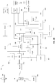
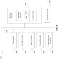
- the UE 100 is generally a mobile device and can include or implement the functionality of various mobile communication and/or computing devices; examples include, but are not limited to, cellphones, personal digital assistants (PDAs), smartphones, computing devices such as laptops, desktops or tablet computers, automobile computing systems, etc., whether presently existing or developed in the future.
- the UE 100 may also be referred to as a mobile station, a mobile device, a terminal, a wireless terminal, a wireless device, an access terminal, a subscriber unit, a station, or by some other name.
- the UE 100 includes a processor 111 (or processor core) and memory 140.
- the UE 100 may optionally include a trusted environment operably connected to the memory 140 by the public bus 101 or a private bus (not shown).
- the UE 100 may also include a communication interface 120 and a wireless transceiver 121 configured to send and obtain wireless signals 123 via a wireless antenna 122 over a wireless network.
- the wireless transceiver 121 is connected to the bus 101 via the communication interface 120.
- the UE 100 is illustrated as having a single wireless transceiver 121.
- a UE 100 can alternatively have multiple wireless transceivers 121 and/or multiple wireless antennas 122 to support multiple communication standards such as WiFi (e.g. IEEE 802.11), CDMA, Wideband CDMA (WCDMA), Long Term Evolution (LTE), Bluetooth®, short-range wireless communication technology, etc.
- WiFi e.g. IEEE 802.11
- CDMA Code Division Multiple Access
- WCDMA Wideband CDMA
- LTE
- the communication interface 120 and/or wireless transceiver 121 may support operation on multiple carriers (waveform signals of different frequencies).
- Multi-carrier transmitters can transmit modulated signals simultaneously on the multiple carriers.
- Each modulated signal may be a Code Division Multiple Access (CDMA) signal, a Time Division Multiple Access (TDMA) signal, an Orthogonal Frequency Division Multiple Access (OFDMA) signal, a Single-Carrier Frequency Division Multiple Access (SC-FDMA) signal, etc.
- Each modulated signal may be sent on a different carrier and may carry pilot, overhead information, data, etc.
- the UE 100 may also include a user interface 150 (e.g., display, keyboard, touchscreen, microphone, speaker), and an SPS receiver 155 that receives satellite positioning system (SPS) signals 159 (e.g., from SPS satellites) via an SPS antenna 158 (e.g. which may be the same as or different to wireless antenna 122).
- SPS receiver 155 can communicate with a single global navigation satellite system (GNSS) or multiple such systems.
- GNSS can include, but is not limited to, the Global Positioning System (GPS), Galileo, Glonass, Beidou (Compass), etc.
- GPS Global Positioning System
- Galileo Galileo
- Glonass Glonass
- Beidou Beidou
- SPS satellites are also referred to as satellites, space vehicles (SVs), etc.
- the SPS receiver 155 processes, in whole or in part, the SPS signals 159 and may use these SPS signals 159 to determine the location of the UE 100 or may enable UE 100 to transfer measurements of the SPS signals to a location server (e.g. an E-SMLC or E-SLP) which computes a location for UE 100 from the measurements.
- the processor 111, memory 140, Digital Signal Processor (DSP) 112 and/or specialized processor(s) may also be utilized to process the SPS signals 159, in whole or in part, and/or to calculate the location of the UE 100, in conjunction with SPS receiver 155. Storage of information from the SPS signals 159 or other location signals is performed using a memory 140 or registers (not shown).
- processor 111 While only one processor 111, one DSP 112 and one memory 140 are shown in FIG. 1 , more than one of any, a pair, or all of these components could be used by the UE 100.
- the processor 111 and DSP 112 associated with the UE 100 are connected to the bus 101.
- the memory 140 can include a non-transitory computer-readable storage medium (or media) that stores functions as one or more instructions or code.
- Media that can make up the memory 140 include, but are not limited to, RAM, ROM, FLASH, disc drives, etc.
- the functions stored by the memory 140 are executed by general-purpose processor(s) 111, specialized processors, or DSP(s) 112.
- the memory 140 is a processor-readable memory and/or a computer-readable memory that stores software (programming code, instructions, etc.) configured to cause the processor(s) 111 and/or DSP(s) 112 to perform the functions described.
- one or more functions of the UE 100 may be performed in whole or in part in hardware.
- location, position, location estimate and position estimate are used interchangeably herein to refer to a location which may be geographic (also referred to as geodetic) or civic.
- a geographic location for a UE 100 may include coordinates such as a latitude, longitude and possibly altitude (e.g. above or below mean sea level or above or below local ground level) or local coordinates (e.g. local X,Y,Z Cartesian coordinates) defined relative to some nearby fixed point.
- a civic location (also referred to as a civic address) for a UE 100 may include a postal address, street address, a name of a well known place or building, a reference to part of a building or structure (e.g. a floor level, room number, apartment number, gate number for an airport).
- a geographic location and a civic location for a UE 100 may refer to the same location for the UE 100 but may be expressed in different ways.
- a civic location for the UE 100 may be referred to as a dispatchable civic location or as a dispatchable location and may be used by the PSAP to dispatch public safety responders to the location of the UE 100.
- a UE 100 may estimate its current position, or obtain information that can be used by another entity such as a location server (e.g. an E-SMLC or E-SLP) to estimate the location of the UE 100, using various techniques, based on other communication entities within view and/or information available to the UE 100. For instance, a UE 100 can estimate its position or enable another entity to estimate the position of UE 100 using information obtained from nearby access points (APs) associated with one or more wireless local area networks (WLANs), personal area networks (PANs) utilizing a short-range wireless communication technology such as Bluetooth or ZIGBEE®, etc., a Global Navigation Satellite System (GNSS) or other Satellite Positioning System (SPS) satellites, and/or map data obtained from a map server.
- APs access points
- WLANs wireless local area networks
- PANs personal area networks
- GNSS Global Navigation Satellite System
- SPS Satellite Positioning System
- a location server which may be an E-SMLC, E-SLP or Standalone Serving Mobile Location Center (SAS), may provide assistance data to a UE 100 to enable or assist the UE 100 to make location related measurements (e.g. measurements of WLAN APs, cellular base stations, GNSS satellites). The UE 100 may then provide the measurements to the location server to compute a location estimate or may compute a location estimate itself based on the measurements and possibly based also on other assistance data provided by the location server (e.g. such as orbital and timing data for GNSS satellites or the precise location coordinates of WLAN APs and/or cellular base stations).
- location related measurements e.g. measurements of WLAN APs, cellular base stations, GNSS satellites.
- the UE 100 may then provide the measurements to the location server to compute a location estimate or may compute a location estimate itself based on the measurements and possibly based also on other assistance data provided by the location server (e.g. such as orbital and timing data for GNSS satellites or the
- a pressure sensor 130 may be included within the UE 100 (e.g., internally) or may be operably coupled to the UE 100 as a peripheral device (e.g., externally).
- the pressure sensor 130 is configured to provide barometric pressure information (e.g., 10-1200 mbar) to the processor(s) 111.
- Examples pressure sensors may include Measurement Specialties MS5607, Bosch BMP085 or BMP280, and STMicroelectronics LPS22HB or LSP331AP. These examples are not limitations as other such piezo-resistive pressure sensors configured to detect atmospheric pressure may be used.
- the pressure sensor 130 is configured to detect ambient barometric pressure and the UE 100 may provide such uncompensated barometric pressure (UBP) information to a communications system (e.g. a location server such as an E-SMLC, E-SLP or SAS).
- UBP uncompensated barometric pressure
- a communications system e.g. a location server such as an E-SMLC, E-SLP or SAS.
- barometric pressure, barometric air pressure and atmospheric pressure are used interchangeably herein to refer to atmospheric pressure - e.g. at the location of the UE 100.
- UBP refers to a measurement of atmospheric pressure by a UE (e.g. by the UE 100 using the pressure sensor 130) in which the pressure measurement is not necessarily adjusted by the UE to compensate for any errors in the measurement.
- a UE 100 may communicate with an access network 202 to obtain communication services.
- the UE 100 may communicate with one or more base stations and/or one or more access points in access network 202.
- the UE 100 may also receive signals from one or more satellites 290, which may be part of the United States Global Positioning System (GPS), the European Galileo system, the Russian GLONASS system, etc.
- GPS Global Positioning System
- the UE 100 may measure signals from base stations and/or APs in access network 202 and obtain measurements of signal timing, signal strength and/or signal quality for the base stations and/or APs.
- the UE 100 may also measure signals from satellites 290 and obtain pseudo-range (or code phase or carrier phase) measurements for the satellites.
- the pseudo-range measurements and/or timing measurements may be used to derive a position estimate for UE 100 either by the UE 100 or by location server 206.
- the UE 100 is also configured to provide uncompensated barometric pressure (UBP) information to the location server 206 (e.g. as measured by pressure sensor 130).
- UBP barometric pressure
- the access network 202 provides radio communication for UEs located within its coverage area.
- the access network 202 may also be referred to as a radio network, a radio access network (RAN), etc.
- the access network 202 may include base stations, access points, network controllers, and/or other entities, as described below.
- a serving core network 204 which may be referred to as a core network or evolved packet core (EPC), may include network entities that may support various communication services.
- a location server 206 may support location services for UEs communicating with serving core network 204 (e.g., including UEs roaming to serving core network 204) and may or may not require the UEs to have any service subscription or any prior relationship to the location server 206.
- the serving core network 204 may also include a Gateway 208 configured to support messaging with PSAPs such as a legacy Emergency Services Network (ESN)/PSAP 210a and an i3 Emergency Services IP network (ESInet)/PSAP 210b.
- ESN Emergency Services Network
- Location server 206 may correspond to an E-SMLC, E-SLP or SAS and may support a control plane location solution (e.g. if location server 206 is an E-SMLC or SAS) or a user plane location solution such as the Open Mobile Alliance (OMA) SUPL solution (e.g. if location server 206 is an E-SLP).
- Location server 206 may interact with UE 100 to (i) transfer assistance data to UE 100 to assist UE 100 to make location related measurements and/or compute a location estimate from such measurements, (ii) request location related measurements and/or a location estimate from UE 100 and/or (iii) receive location related measurements and/or a location estimate from UE 100.
- Location server 206 may compute a location estimate (e.g.
- Location server 206 may interact with UE 100 using one or more of a number of different positioning protocols including (i) the LTE Positioning Protocol (LPP) defined by 3GPP, (ii) the LPP Extensions (LPPe) protocol defined by OMA, (iii) the Positioning Calculation Application Part (PCAP) plus Radio Resource Control (RRC) protocols for UMTS defined by 3GPP, (iv) the SUPL UserPlane Location Protocol (ULP) defined by OMA, and (v) the LTE Positioning Protocol A (LPPa) plus RRC protocol for LTE defined by 3GPP.
- LTP LTE Positioning Protocol
- LPPe LPP Extensions
- PCAP Positioning Calculation Application Part
- RRC Radio Resource Control
- UE 100 and location server 206 may interact using LPP combined with LPPe when location server is an E-SMLC or E-SLP.
- LPP combined with LPPe may be referred to as LPP/LPPe and may include transferring LPP messages where each LPP message embeds a single LPPe message - e.g. as defined for LPP in 3GPP TS 36.355.
- Gateway 208 may correspond to a Gateway Mobile Location Center (GMLC) or Location Retrieval Function (LRF) as defined by 3GPP (e.g. in 3GPP Technical Specifications (TSs) 23.167 and 23.271) and may instigate positioning of UE 100 via location server 206 - e.g. when Gateway 208 receives a location request for UE 100 from legacy ESN/PSAP 210a or i3 ESInet/PSAP 210b. Gateway 208 may then receive location information for UE 100 (e.g.
- GMLC Gateway Mobile Location Center
- LRF Location Retrieval Function
- HALI that may comprise a dispatchable civic location and/or a geographic location) via one or more intermediate entities in serving core network from location server 206 or directly from location server 206 and may send the location information to legacy ESN/PSAP 210a or i3 ESInet/PSAP 210b.
- Location server 206, Gateway 208 or some other entity in serving core network 204 may query a National Emergency Address Database (NEAD) 212 for a civic location for UE 100.
- NEAD National Emergency Address Database
- UE 100 may provide location server 206 with the identities (e.g. MAC addresses) of one or more WLAN APs and/or Bluetooth beacons visible to UE 100 and location server 206 or some other entity in serving core network 204 may provide these identities to NEAD 212.
- NEAD 212 may then search a database of known WLAN APs and/or Bluetooth beacons for which corresponding civic location information (e.g. a street address and/or building designation, floor level and possibly room or apartment number) was previously configured and may return a civic location for each of one or more of the identified APs and/or beacons .
- corresponding civic location information e.g. a street address and/or building designation, floor level and possibly room or apartment number
- the location server 206 may then convert the one or more civic locations returned by NEAD 212 into a dispatchable civic location - e.g. by selecting a civic location returned by NEAD 212 for a WLAN AP or Bluetooth beacon that appears to be closest to the location of UE 100 as inferred from measurements (e.g. for RSSI or RTT) by UE 100 of signals from the identified WLAN APs and/or Bluetooth beacons.
- This dispatchable civic location information may, for example, then be transferred to gateway 208 as part of HALI for UE 100.
- the NEAD 212 may receive operations, administration, maintenance and provisioning functions from a National Emergency Address Manager (NEAM) 214.
- the NEAM 214 may receive civic location information from one or more external data sources 216.
- An external data source 216 may correspond to an operator, user or organization that owns or operates one or more reference points (e.g. WLAN APs and/or Bluetooth beacons) that may form one or more access networks.
- the civic location information that is provided may correspond to civic location information for the reference points that are owned or operated.
- the external data sources 216 may have unique identities that can be authenticated by the NEAM 214 and may establish some minimum level of trust in order to receive authorization to provide civic location information.
- the NEAM 214 may be configured to support identification and authentication of external data sources, validation of received civic location information, and provisioning of civic location information in the NEAD 212.
- the UE 100 initiates an emergency call request after detecting an emergency call request from the user of UE 100 (e.g. when the user dials "911").
- the serving core network 204 is configured to support the establishment of the emergency call from the UE 100 to a legacy or National Emergency Number Association (NENA) i3-capable emergency services network and its PSAPs (e.g., 210a, 210b). Functions supported by the serving core network 204 may include emergency call detection, call routing and provision of a dispatchable location. In an example, for a UE 100 with a valid subscription, the serving core network 204 may also support callback from a PSAP.
- NENA National Emergency Number Association
- the legacy ESN/PSAP 210a is configured to receive emergency calls and associated dispatchable location information from the serving core network 204 (e.g. from the Gateway 208), such as defined in Telecommunications Industry Association (TIA) and Alliance for Telecommunications Industry Solutions (ATIS) joint standard J-STD-036.
- the i3 ESInet/PSAP 210b is configured to receive emergency calls and dispatchable location information from the serving core network 204 (e.g. from the Gateway 208) using next generation means (e.g., such as defined in NENA i3).
- a long term evolution (LTE) architecture 300 for transferring UBP information with 3GPP LTE access is shown.
- a UE 100 may communicate with a serving evolved Node B (eNB) 302 in a radio access network (RAN) to obtain communication services.
- the RAN may correspond to access network 202 in FIG. 2 , may include other network entities not shown in FIG. 3A for simplicity and may be referred to as an Evolved Universal Terrestrial Radio Access Network (E-UTRAN).
- E-UTRAN Evolved Universal Terrestrial Radio Access Network
- the eNB 302 may be referred to as a Node B, a base station, an access point, etc.
- the UE 100 may measure signals from nearby eNBs (e.g.
- the UE 100 may also or instead measure pseudo-ranges for SPS satellites 290.
- the eNB identities, eNB timing measurements, eNB signal strength measurements, eNB signal quality measurements and/or SPS pseudo-range measurements may be used to derive a location estimate for UE 100 (e.g. by UE 100 or by a location server such as E-SMLC 308 or E-SLP 332).
- the UE 100 may also or instead receive and optionally measure signals from nearby APs in a WLAN 390 which may include obtaining identities (e.g. MAC addresses) for WiFi or Bluetooth (BT) APs (which may also be referred to as beacons) in WLAN 390 whose signals can be received by UE 100 and possibly measuring characteristics of these received signals such as Received Signal Strength Indication (RSSI) or Round Trip signal propagation Time (RTT).
- identities e.g. MAC addresses
- BT Bluetooth
- RTT Round Trip signal propagation Time
- the WLAN AP identities and measurements may be used to obtain a location for UE 100 - e.g. by UE 100 or by a location server such as E-SMLC 308 or E-SLP 332.
- the eNB and/or WLAN AP identities may be used to query the NEAD 212 (e.g.
- WLAN 390 is shown in FIG. 3A , there may be other WLANs (not shown in FIG. 3A ) containing WiFi and/or BT APs that are visible to UE 100; reference herein to WLAN 390 is therefore to be considered as referring possibly to more than one WLAN.
- the eNB 302 may communicate with a serving MME 304 for UE 100, which may perform various control functions such as mobility management, gateway selection, authentication, bearer management, etc.
- MME 304 may communicate with an Enhanced Serving Mobile Location Center (E-SMLC) 308 and a Gateway Mobile Location Center (GMLC) 306.
- E-SMLC 308 may support UE-based, UE-assisted, network-based and/or network-assisted positioning methods for UE 100 and may support one or more MMEs (e.g. MME 304).
- the E-SMLC 308 may also be referred to as a location server (LS), a Stand Alone SMLC (SAS), etc.
- E-SMLC 308 may communicate with the NEAD 212 to support location services.
- E-SMLC 308 may correspond to location server 206 in FIG. 2 .
- the GMLC 306 may perform various functions to support location services, interface with external clients (e.g., the NEAD 212), and provide services such as subscriber privacy, authorization, authentication, billing, etc.
- a Location Retrieval Function (LRF) 330 may communicate with GMLC 306 and may route or help route IP-based emergency calls to a Public Safety Answering Points (PSAPs) such as the i3 ESInet 342 and i3 PSAP 344, and well as legacy systems such as the legacy ES network 346 and the legacy PSAP 348.
- PSAPs Public Safety Answering Points
- An Emergency SUPL Location Platform (E-SLP) 332, including SUPL Positioning Center (SPC) 334 and a SUPL Location Center (SLC) 336, are also configured to communicate location information with the LRF 330.
- the E-SLP 332 is an example of a location server 206 and the LRF 330 is an example of a Gateway 208 in the serving core network 204. In some networks, E-SLP 332 may be deployed but not E-SMLC 308 or vice versa.
- a Serving Gateway 316 may perform various functions related to IP data transfer for UEs such as data routing and forwarding, mobility anchoring, etc.
- a Packet Data Network (PDN) Gateway 318 may perform various functions such as maintenance of data connectivity for UEs, IP address allocation, etc.
- An IP Multimedia Subsystem (IMS) network may include various network entities to support IMS services such as Voice-over-IP (VoIP) calls.
- VoIP Voice-over-IP
- the IMS network may include the LRF 330, a Proxy Call Session Control Function (P-CSCF) 320, a Serving Call Session Control Function (S-CSCF) 322, an Emergency Call Session Control Function (E-CSCF) 324, a Breakout Gateway Control Function 340, a media gateway control function (MGCF) 338, an Interconnection Border Control Function (IBCF) 326, and a Routing Determination Function (RDF) 328.
- P-CSCF Proxy Call Session Control Function
- S-CSCF Serving Call Session Control Function
- E-CSCF Emergency Call Session Control Function
- MGCF media gateway control function
- IBCF Interconnection Border Control Function
- RDF Routing Determination Function
- the LTE architecture 300 may utilize LTE interfaces and protocols for control plane location.
- the LPP protocol defined in 3GPP TS 36.355 combined with the OMA LPPe protocol may be used over the Uu interface between the UE 100 and the eNB 302 for positioning of the UE 100 by the E-SMLC 308.
- LPP/LPPe messages may be transferred between the UE 100 and the E-SMLC 308 via the MME 304 and the eNB 302 for the UE 100 as described in 3GPP TSs 23.271 and 36.305.
- the E-SMLC 308 may be configured to request (e.g.
- LPP/LPPe Request Location Information message by sending an LPP/LPPe Request Location Information message to UE 100), and the UE 100 may be configured to provide (e.g. by sending an LPP/LPPe Provide Location Information message to E-SMLC 308) the identities of visible WLAN APs, signal measurements of visible WLAN APs (e.g. RSSI, RTT), and an uncompensated barometric pressure (UBP) if supported by the UE 100.
- This information is supported in the OMA LPPe version 1.0, version 1.1 and version 2.0 protocols.
- either (i) the LPP protocol alone without LPPe or (ii) the Radio Resource Control (RRC) protocol for LTE defined in 3GPP 36.331 may be used over the Uu interface between the UE 100 and the serving eNB 302 for positioning of the UE 100 by the E-SMLC 308.
- RRC Radio Resource Control
- LPP messages may be transferred between the UE 100 and the E-SMLC 308 via the MME 304 and the serving eNB 302 for the UE 100 as described in 3GPP TSs 23.271 and 36.305.
- RRC messages may be transferred between the UE 100 and the serving eNB 302 and LTE Positioning Protocol A (LPPa) messages may be transferred between eNB 302 and E-SMLC 308 via the MME 304 for the UE 100 as described in 3GPP TSs 23.271 and 36.305.
- LPPa LTE Positioning Protocol A
- the E-SMLC 308 may be configured to request (e.g. by sending an LPP Request Location Information message to UE 100 or an LPPa request message to eNB 302 which may cause eNB 302 to send an RRC request message to UE 100), and the UE 100 may be configured to provide (e.g.
- E-SMLC 308 by sending an LPP Provide Location Information message to E-SMLC 308 or an RRC response to eNB 302 which causes eNB 302 to send an LPPa response to E-SMLC 308) the identities of visible WLAN APs, signal measurements of visible WLAN APs (e.g. RSSI, RTT), and an uncompensated barometric pressure (UBP) if supported by the UE 100.
- LPP Provide Location Information message to E-SMLC 308 or an RRC response to eNB 302 which causes eNB 302 to send an LPPa response to E-SMLC 308
- the identities of visible WLAN APs e.g. RSSI, RTT
- signal measurements of visible WLAN APs e.g. RSSI, RTT
- UBP uncompensated barometric pressure
- a Location Services (LCS) Application Protocol (LCS-AP) defined in 3GPP TS 29.171 may be used over the SLs interface between the MME 304 and the E-SMLC 308 to enable the MME 304 to request location information for the UE 100 from the E-SMLC 308 using the 3GPP control plane solution.
- the LCS-AP protocol may enable the E-SMLC 308 to return the HALI to the MME 304.
- ELP Evolved Packet Core
- 3GPP TS 29.172 An Evolved Packet Core (EPC) LCS Protocol (ELP) defined in 3GPP TS 29.172 may be used over the SLg interface between the MME 304 and the GMLC 306 to enable the GMLC 306 to request and obtain location information for the UE 100 using the 3GPP control plane solution.
- ELP protocol may enable the MME 304 to return HALI to the GMLC 306.
- a L0 interface may be used between the LRF 330 and the GMLC 306 to enable the LRF 330 to request location information for the UE 100 from the GMLC 306 using a control plane solution in the case that the UE 100 is establishing or has established an IMS emergency call to a PSAP (e.g.
- the L0 interface may enable the GMLC 306 to return HALI to the LRF 330.
- Possible protocols defined for the L0 interface may include the Mobile Location Protocol (MLP) defined by OMA, the Hypertext Transfer Protocol (HTTP) Enabled Location Delivery (HELD) protocol defined by the Internet Engineering Task Force (IETF), and the E2 interface protocol defined in TIA/ANSI joint standard J-STD-036.
- MLP Mobile Location Protocol
- HTTP Hypertext Transfer Protocol
- HELD Enabled Location Delivery
- IETF Internet Engineering Task Force
- E2 interface protocol defined in TIA/ANSI joint standard J-STD-036.
- An Le E2 interface may be used between the LRF 330 and an entity (e.g.
- an Automatic Location Identification (ALI) entity) in a legacy emergency services (ES) network 346 to enable the legacy ES network 346 to request location information for the UE 100 from the LRF 330 in the case that the UE 100 establishes an emergency call to a legacy PSAP 348.
- the Le E2 interface may use either the E2 protocol defined in TIA/ANSI joint standard J-STD-036 and in the NENA-05-001 standard from NENA or the Mobile Location Protocol (MLP) defined by OMA.
- An Le i3 interface may be used between the LRF 330 and the emergency services i3 network (ESInet) 342 to enable an entity in or connected to the ESInet 342 (e.g.
- an Emergency Services Routing Proxy or the i3 PSAP 3414 to request location information for the UE 100 from the LRF 330 in the case that the UE establishes or has established an emergency call to the i3 ESInet 342.
- the Le i3 interface may use HELD, MLP, or the IETF Session Initiation Protocol (SIP) SUBSCRIBE/NOTIFY protocol.
- the LTE architecture 300 may also or instead utilize interfaces and protocols for SUPL User Plane Location.
- a Lup interface as defined in OMA TS OMA-AD-SUPL-V2_0 may be used between the UE 100 (referred to as a SUPL Enabled Terminal (SET)) and the E-SLP 332 to support positioning of the UE 100 using the OMA SUPL user plane solution.
- the E-SLP 332 may be configured to be used in the serving core network for the UE 100.
- the Lup interface enables exchange of ULP messages, defined in OMA-TS-ULP-V2_0_3, between the UE 100 and the E-SLP 332.
- the E-SLP 332 may be split logically or physically into the SLC 336 and the SPC 334.
- the SLC 336 is configured to establish and control a SUPL session with the UE 100.
- the SPC 334 is configured to obtain a location of the UE 100.
- the endpoint for any ULP message is then either the SLC 336 or the SPC 334 depending on whether the ULP message is used for control and service provision or for positioning, respectively.
- the ULP messages used for positioning typically encapsulate one or more LPP messages. Each encapsulated LPP message can further encapsulate one LPPe message.
- LPP/LPPe may be used to enable the SPC 334 to request, and the UE 100 to return the same information as described for control plane location above using LPP, LPP/LPPe or RRC/LPPa.
- An Internal Location Protocol defined in OMA TS OMA-TS-ILP-V2_0_3 may be used over the L1p interface between an SLC 336 and SPC 334 to enable the SLC 336 to instigate positioning of the UE 100 using the SPC 334 and to obtain location information for the UE 100 from the SPC 334.
- the ILP protocol may enable an SPC 334 to return HALI to the SLC 336.
- An L0 interface may be used between the LRF 330 and the E-SLP 332 to enable the LRF 330 to request location information for the UE 100 from the E-SLP 332 using the SUPL solution in the case that the UE 100 establishes or has established an IMS emergency call to a PSAP (e.g. legacy PSAP 348 or i3 PSAP 344).
- a PSAP e.g. legacy PSAP 348 or i3 PSAP 344
- the L0 interface enables the E-SLP 332 to return heightened accuracy location information to the LRF 330.
- Possible protocols defined for the L0 interface may include MLP, HELD and the E2 interface protocol defined in TIA/ATIS joint standard J-STD-036.
- the Le E2 and Le i3 interfaces in the user plane may be the same as those described for control plane location above.
- the UMTS architecture 350 includes a carrier network with a Node B 352, an radio network controller (RNC) 356, a stand-alone SMLC (SAS) 354, a mobile switching center (MSC) server 358, a GMLC 306, a serving GPRS support node (SGSN) 360, a gateway GPRS support node (GGSN) 362, in addition to the elements as depicted in FIG. 3A and previously described that are also present in FIG. 3B .
- the SAS 354 is an example of a location server 206 in a serving core network 204.
- An RRC protocol for UMTS defined in 3GPP TS 25.331 may be used over the Uu interface for positioning of the UE 100 by the RNC 356 in the case of control plane location with Circuit Switched (CS) access.
- the RNC 356 is configured to request, and the UE 100 is configured to provide the identities of visible WLAN APs (e.g. APs in WLAN 390), and an uncompensated barometric pressure (UBP), if supported by the UE 100.
- visible WLAN APs e.g. APs in WLAN 390
- UBP uncompensated barometric pressure
- a Positioning Calculation Application Part (PCAP) protocol as defined in 3GPP TS 25.453 may be used over the Iupc interface between the RNC 356 for the UE 100 and the SAS 354 to enable the RNC 356 to request location information for the UE 100 from the SAS 354 using the 3GPP control plane solution.
- PCAP Positioning Calculation Application Part
- the RNC 356 and the SAS 354 can interact using PCAP in either a SAS centric mode where the SAS 354 controls the use of different position methods and RNC 356 interaction with the UE 100, or in RNC centric mode where the RNC 356 controls the use of different position methods and all interaction with the UE 100 and invokes the SAS 354 only to provide assistance data for the UE 100 or to compute a location from location related measurements provided by the UE 100 to the RNC 356.
- the PCAP protocol may enable the RNC 356 to transfer the additional location information provided using RRC by the UE 100 (e.g. measurements of WLAN 390 and/or UBP).
- a Radio Access Network Application Part (RANAP) protocol defined in 3GPP TS 25.413 may be used over the Iu-cs interface between the MSC server 358 for the UE 100 and the RNC 356 to enable the MSC server 358 to request location information for the UE 100 from the RNC 356 using the 3GPP control plane solution.
- a Mobile Application Part (MAP) protocol as defined in 3GPP TS 29.002 may be used over the Lg interface between MSC server 358 for the UE 100 and the GMLC 306 to enable the GMLC 306 to request and obtain location information for the UE 100 using the 3GPP control plane solution.
- a Le E2 interface may be used between the GMLC 306 and an entity (e.g.
- the Le E2 interface is defined in TIA/ATIS joint standard J-STD-036 and in the NENA-05-001 standard (from NENA).
- the UMTS architecture 350 also supports interfaces and protocols within and to a serving UMTS network to support heightened accuracy location in the case of Packet Switched (PS) access and control plane location.
- the RRC protocol as defined in 3GPP TS 25.331 may be used over the Uu interface for positioning of the UE 100 by the RNC 356 in the case of control plane location with PS access.
- the PCAP protocol as defined in 3GPP TS 25.453 may be used over the Iupc interface between the RNC 356 for the UE 100 and the SAS 354 to enable the RNC 356 to request location information for the UE 100 from the SAS 354 using the 3GPP control plane solution.
- the RANAP protocol defined in 3GPP TS 25.413 may be used over the Iu-ps interface between the SGSN 360 for the UE 100 and the RNC 356 to enable the SGSN 360 to request location information for the UE 100 from the RNC 356 using the 3GPP control plane solution.
- the MAP protocol defined in 3GPP TS 29.002 may be used over the Lg interface between the SGSN 360 for the UE 100 and the GMLC 306 to enable the GMLC 306 to request and obtain location information for the UE 100 using the 3GPP control plane solution.
- the ELP protocol defined in 3GPP TS 29.172 may be used over the Lgd interface between the SGSN 360 for the UE 100 and the GMLC 306 to enable the GMLC 306 to request and obtain location information for the UE 100 using the 3GPP control plane solution.
- the Lgd interface is applicable to an SGSN that supports 3GPP Evolved Packet System (EPS) based interfaces and protocols.
- EPS Evolved Packet System
- the L0 interface may be used between the LRF 330 and the GMLC 306 to enable the LRF 330 to request location information for the UE 100 from the GMLC 306 using the 3GPP control plane solution in the case that the UE 100 is establishing or has established an emergency call to a PSAP (e.g.
- the L0 interface may enable the GMLC 306 to return heightened accuracy location information to the LRF 330.
- Possible protocols defined for the L0 interface include MLP, HELD and the E2 interface protocol defined in J-STD-036.
- the Le E2 interface may be used between the LRF 330 and the legacy ES network 346 in a legacy emergency services network to enable the legacy ES network 346 to request location information for the UE 100 from the LRF 330 in the case that the UE 100 has established an emergency call to legacy PSAP 348 using PS access.
- the Le E2 interface may use the E2 protocol defined in TIA/ATIS joint standard J-STD-036 and in NENA-05-001 or the OMA MLP protocol.
- the Le i3 interface may be used between the LRF 330 and an emergency services i3 network (ESInet) 342 to enable an entity in or connected to the ESInet (e.g. an ESRP or i3 PSAP 344) to request location information for the UE 100 from LRF 330 in the case that the UE 100 is establishing or has established an emergency call to the ESInet 342 using PS access.
- ESInet emergency services i3 network
- the Le i3 interface may use HELD, MLP or SIP SUBSCRIBE/NOTIFY.
- the UMTS architecture 350 also or instead supports interfaces and protocols within UMTS PS Access to support heightened accuracy location in the case of user plane location.
- the Lup interface as defined in OMA specification OMA-AD-SUPL-V2_0 may be used between the UE 100 and the E-SLP 332 to support positioning of the UE 100 using the OMA SUPL user plane solution.
- the Lup interface enables exchange of SUPL ULP messages, defined in OMA TS OMA-TS-ULP-V2_0_3, between the UE 100 being positioned and the E-SLP 332.
- the E-SLP 332 is split into the SLC 336 and the SPC 334 with the SLC 336 being used to establish and control a SUPL session between the UE 100 and the E-SLP 332 and the SPC 334 being used to obtain a location of the UE 100.
- the endpoint for any SUPL ULP message is either the SLC 336 or the SPC 334 depending on whether the ULP message is used for control and service provision (when the end point is the SLC 336) or for positioning (when the endpoint is the SPC 334).
- ULP messages used for positioning may encapsulate one or more LPP messages or one or more RRC messages for the RRC protocol defined in 3GPP TS 25.331.
- each encapsulated LPP message can further encapsulate one LPPe message.
- LPP, LPP/LPPe or RRC may be used to enable the SPC 334 to request and the UE 100 to return the same information as described for control plane location (e.g. measurements for WLAN 390 and/or UBP).
- the ILP protocol as defined in OMA TS OMA-TS-ILP-V2_0_3 may be used over the L1p interface between the SLC 336 and SPC 334 to enable the SLC 336 to instigate positioning of the UE 100 using the SPC 334 and to obtain location information for the UE 100 from the SPC 334.
- the L0 interface may be used between the LRF 330 and the E-SLP 332 to enable the LRF 330 to request location information for the UE 100 from the E-SLP 332 in the case that the UE 100 is establishing or has established an IMS emergency call to a PSAP (e.g. legacy PSAP 348 or i3 PSAP 344).
- PSAP e.g. legacy PSAP 348 or i3 PSAP 344.
- Possible protocols defined for the L0 interface include MLP, HELD and the E2 interface protocol defined in J-STD-036.
- the impacts for the Le E2 and the Le i3 interface are the same as those for UMTS control plane location previously described.
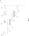
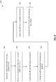
- a message flow diagram 400 of an example UBP transfer procedure with civic location information is shown.
- the nodes in the message flow include a UE 402, a serving network 404, and a PSAP 406.
- the UE 402 may correspond to the UE 100 in FIG.s 1-3B .
- the serving network 404 may include one or more elements of the serving core network 204 in FIG. 2 and/or the LTE and UMTS architectures 300, 350 as depicted in FIGS. 3A and 3B .
- the PSAP 406 may correspond to the legacy PSAP 348 or the i3 PSAP 344.
- uncompensated barometric pressure may be transferred from the UE 402 to the PSAP 406 (e.g., i3 PSAP 344, legacy PSAP 348) via a location server in the serving network 404 (e.g. location server 206, E-SMLC 308, E-SLP 332 or SAS 354) and a gateway in the serving network 404 (e.g. Gateway 208, GMLC 306 or LRF 330).
- the pressure sensor 130 in the UE 402 may be configured to measure UBP
- the processor 111 and the wireless transceiver 121 may be configured to provide the UBP to serving core network 404 via a first message 408.
- the first message 408 can be provided by the UE 402 to a location server (e.g. an E-SMLC 308, E-SLP 332 or SAS 354) using LPPe where LPPe may be used in combination with LPP (i.e. as LPP/LPPe).
- LPPe LPPe may be used in combination with LPP (i.e. as LPP/LPPe).
- the UBP supported in LPPe may be in units of Pascal (Pa) with a range of 30,000 to 115,000 Pa in one embodiment. Other measurement units (e.g., millibars) and ranges may also be used for UBP. In general, the UBP range should be sufficient to represent possible indoor or outdoor atmospheric pressures at any likely altitude for the UE 402.
- the first message 408 can be provided by the UE 402 to a location server (e.g.
- LPP LPP
- RRC for LTE e.g. between UE 402 and a serving eNB like eNB 302
- LPPa e.g. between a serving eNB and E-SMLC 308
- RRC for UMTS e.g. between UE 402 and a serving RNC like RNC 356
- PCAP e.g. between a serving RNC and SAS 354
- the serving network 404 (e.g. a location server 206 in serving network 404 such as E-SMLC 308, E-SLP 332, SPC 334 or SAS 354) is configured to combine the UBP received via the first message 408 with civic location information for UE 402.
- the civic location information may be provided by a NEAD such as NEAD 212 as described previously.
- Existing internet standards e.g., IETF RFC 6848
- IANA Internet Assigned Numbers Authority
- PIDF-LO Presence Information Data Format Location Object
- DHCP Dynamic Host Configuration Protocol
- a civic address type based on this mechanism may be registered to convey UBP as a number (e.g. a decimal or binary number in units of Pascal or millibars).
- a dispatchable civic location for a UE 402 is determined at a location server (e.g. location server 206, E-SMLC 308, SAS 354, SPC 334 or E-SLP 332) using one or more civic locations for the UE 402 received from the NEAD 212 (e.g. as described previously in association with FIG. 2 ) and if UBP is also received at the location server from the UE 402, at stage 410 the location server in the serving network 404 can combine the UBP into the civic location using the civic address type that was registered with IANA to convey UBP.
- a location server e.g. location server 206, E-SMLC 308, SAS 354, SPC 334 or E-SLP 332
- the location server in the serving network 404 can combine the UBP into the civic location using the civic address type that was registered with IANA to convey
- a message containing the combined dispatchable civic location and UBP parameter 412 can be transferred and processed transparently through intermediate entities (e.g. one or more of MME 304, GMLC 306, SLC 336, RNC 356, MSC Server 358, SGSN 360), and as far as a gateway to the PSAP (e.g. either a GMLC 306 or LRF 330).
- the combined dispatchable civic location and UBP parameter 412 is transferred using the IETF HELD protocol, OMA MLP or the J-STD-036 E2 protocol to the PSAP 406 with the PSAP 406 presenting both the dispatchable civic location and UBP measurement to the PSAP 406 operator (not shown in FIG. 4 ).
- the gateway e.g.
- GMLC 306 or LRF 330 in the serving network 404 may extract the UBP from the received dispatchable civic location and UBP parameter 412 and transfer the UBP separately to the PSAP 406 (e.g. using a new parameter for HELD, MLP or the E2 protocol).
- the location server in the serving network 404 may be configured to construct an empty dispatchable civic location parameter 412 which contains only the UBP. This empty dispatchable civic location (e.g., just the UBP) may be conveyed in the same manner as for the combined dispatchable civic location and UBP parameter 412 as previously described.
- the flow diagram 400 may be modified based on evolving data formats, interfaces and protocols.
- a new civic address (CA) type may be registered with IANA specifically to carry UBP as described above.
- a new civic address type may be registered with IANA to carry environmental data for the location of a UE such as temperature, humidity as well as UBP.
- a new miscellaneous civic address type may be registered with IANA to carry miscellaneous information that does not fit elsewhere within a civic location and whose content is not constrained or defined by IANA.
- nnnnnn is a sequence of decimal digits representing the value of UBP expressed in decimal.
- An existing civic address type already registered with IANA may also be used to convey UBP.
- civic address type 22 contains additional (i.e., unspecified) location information
- civic address type 32 (referred to as ADDCODE) allows an additional numeric code.
- message call flow diagram 500 shows another example of a UBP transfer procedure with geographic location information.
- the nodes in the message call flow include a UE 502, a location server 504, a Gateway 506, and a PSAP 508.
- the UE 502 may correspond to UE 100 in FIG.s 1-3B .
- the location server 504 and gateway 506 may correspond to one or more elements of the communication system 200 and/or the LTE and UMTS architectures 300, 350, as depicted in FIGS. 2 , 3A and 3B .
- location server 504 may correspond to location server 206, E-SMLC 308, E-SLP 332, SPC 334 or SAS 354.
- Gateway 506 may correspond to Gateway 208, LRF 330 or GMLC 306.
- the PSAP 508 may correspond to the legacy PSAP 348 or the i3 PSAP 344.
- uncompensated barometric pressure UBP
- UBP uncompensated barometric pressure
- the PSAP 508 e.g., i3 PSAP 344, legacy PSAP 348
- the location server 504 e.g. location server 206, E-SMLC 308, SAS 354 or E-SLP 332
- the Gateway 506 e.g. Gateway 208, GMLC 306 or LRF 330.
- the pressure sensor 130 in the UE 502 may be configured to measure UBP, and the processor 111 and the wireless transceiver 121 may be configured to provide the UBP to the location server 504 via a first message 510.
- the first message 510 is provided by the UE 502 to the location server 504 (e.g. an E-SMLC 308, SAS 354 or E-SLP 332) using LPPe where LPPe may be used in combination with LPP (e.g. as LPP/LPPe).
- the first message 510 may be provided by the UE 502 to a location server 504 (e.g.
- a geographic location of the UE 502 may be determined by the location server 504 or may be received at the location server 504 from the UE 502.
- the location server 504 is configured to combine the geographic location with UBP (e.g., as received from the UE 502 in the first message 510).
- a combined geographic location and UBP parameter 514 may then be transferred to the Gateway 506 (e.g., the GMLC 306 or LRF 330).
- the transfer of the combined geographic location and UBP parameter may be transparent to intermediate entities in a serving network (e.g. may be transparent to one or more of MME 304, GMLC 306, SLC 336, RNC 356, MSC Server 358, SGSN 360).
- the combined geographic location and UBP parameter 514 may further be transferred transparently from location server 504 to Gateway 506 using the existing interfaces and protocols for a 3GPP control plane location solution or SUPL user plane location solution that were described previously in association with FIG.s 3A and 3B .
- These interfaces may include one or more of the 3GPP SLs, SLg, L0, Lg, Lgd, Iupc, Iu-cs and Iu-ps interfaces).
- any empty (Null) geographic location may be created by the location server 504 to transfer the UBP as far as the Gateway 506 (e.g.
- the Gateway 506 (e.g., GMLC 306 or LRF 330) is configured to parse the combined geographic location and UBP parameter 514 and remove the UBP from the geographic location (or from a Null geographic location if the geographic location is empty).
- the removed UBP may be sent as a separate parameter to the PSAP 508.
- the Gateway 506 may send the removed UBP as a parameter in message 518 to the PSAP 508.
- geographic location may be represented in 3GPP protocols by octet strings defined in 3GPP TS 23.032.
- the location server 504 may be configured to concatenate a small fixed number (e.g. two or three) of additional octets with a geographic location octet string to convey UBP.
- the UBP may be encoded as a binary value in units of Pa using three additional octets added to a geographic location string.
- the additional octets may be concatenated at the end of a geographic location string and may be detected (e.g.
- a Gateway 506 by determining that the length of the combined geographic location string and UBP exceeds the length defined for the type of the geographic location (e.g. as indicated by the first octet in the geographic location string) by the known fixed number of octets used to encode the UBP.
- the gateway 506 may then be configured to parse the additional UBP octets from the combined geographic location and UBP parameter.
- the UBP could be included by the location server 504 in the altitude coordinate of a geographic location.
- there are two types of geographic location shapes that contain altitude e.g., as standardized in TS 23.032).
- the two geographic location shapes include the ellipsoid point with altitude, and the ellipsoid point with altitude and uncertainty ellipsoid.
- the altitude coordinate is 2 octets which would support inclusion of UBP in units of Pa to a precision of two Pa.
- the UBP may be converted to an equivalent altitude (or depth) for some fixed reference sea level pressure (not related to any current sea level pressure) using a known algorithm by the location server 504 (e.g.
- Serving networks may be configured to determine whether the altitude coordinate of a geographic location represents UBP information or real altitude.
- a network may only support one type of altitude coordinate for all UEs - e.g. either altitude encoding UBP or a real altitude.
- a convention may be employed in a network to distinguish an altitude coordinate carrying a UBP from an altitude coordinate representing real altitude. Such a convention would allow a serving network to support both real altitude and altitude encoding a UBP.
- one possible convention to distinguish a real altitude from an altitude value encoding a UBP may include using a 7 bit uncertainty altitude in the case of an ellipsoid point with altitude an uncertainty ellipsoid (e.g. set the value of the uncertainty to zero, which normally means no error, to indicate UBP).
- Another example convention, applicable to both the ellipsoid point with altitude and the ellipsoid point with altitude and uncertainty ellipsoid includes reserving a range of altitude values that will normally not occur to encode UBP.
- a Mobile Location Protocol (MLP) data structures may be used to define a UBP parameter.
- MLP Mobile Location Protocol
- geographic location shapes may be defined as character strings using XML.
- Existing or new XML tags may be used to define a UBP parameter.
- a location server may determine a dispatchable civic location for a UE (e.g. UE 100) using one or more civic locations for the UE received from the NEAD 212 (e.g. as described previously in association with FIG. 2 ).
- the location server may then convey the determined dispatchable civic location within a PIDF-LO location object (e.g., as defined in RFCs 5139 and 6848) which may be transferred to a gateway (e.g. GMLC 306 or LRF 330) and then either transferred without change to the PSAP (e.g.
- a PIDF-LO location object may include a civic location, a geographic location or a civic location plus geographic location as well as a number of other location related parameters such as a date/timestamp and privacy requirements.
- the geographic location component of a PIDF-LO may not need to be used as geographic location transfer from a location server to a gateway in a serving network may be supported by other existing parameters in applicable 3GPP and OMA protocols for the 3GPP control plane location solution and OMA SUPL user plane location solution.
- a location server e.g. E-SMLC 308, E-SLP 332 or SAS 354 may combine a UBP (e.g. received from a UE 100 or UE 502) into a PIDF-LO using a new or existing parameter, new or existing field or other new or existing value in a PIDF-LO to support inclusion of a UBP.
- the PIDF-LO containing the UBP may then be transferred to a PSAP via a gateway (e.g. Gateway 208, LRF 330 or GMLC 306) or may be transferred as far as a gateway where the UBP is extracted from the PIDF-LO and transferred separately to a PSAP.
- a gateway e.g. Gateway 208,
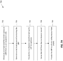
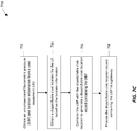
- a process 600 for providing UBP and civic location information to a PSAP includes the stages shown.
- the process 600 is, however, an example only and not limiting.
- the process 600 can be altered, e.g., by having stages added, removed, rearranged, combined, and/or performed concurrently.
- UBP information may be obtained by a serving network prior to obtaining the civic location information.
- the UBP and civic location information may be provided to a PSAP in one or more messages.
- the process 600 may be executed on one or more computer systems such as depicted in FIG. 9 .
- a serving core network 204 is configured to obtain a dispatchable civic location for a user equipment (UE) 100.
- the serving core network 204 may include a location server 206 such as an E-SMLC 308, E-SLP 332, and/or SAS 354 as a means to obtain civic location information (e.g. comprising one or more civic locations) for the UE 100 from a NEAD 212 and obtain a dispatchable civic location from this civic location information (e.g. as described previously in association with FIG. 2 ).
- a location server 206 such as an E-SMLC 308, E-SLP 332, and/or SAS 354 as a means to obtain civic location information (e.g. comprising one or more civic locations) for the UE 100 from a NEAD 212 and obtain a dispatchable civic location from this civic location information (e.g. as described previously in association with FIG. 2 ).
- the civic location information may be obtained by the NEAD 212 based on (i) one or more Media Access Control (MAC) addresses and/or other addresses associated with one or more WiFi and/or BT APs visible to UE 100, (ii) Base Station IDs (e.g. eNB or Home eNB cell identities (IDs)) visible to the UE 100, or (iii) other geographic information such as the current location of the UE 100.
- MAC Media Access Control
- IDs e.g. eNB or Home eNB cell identities (IDs)
- Access to the NEAD 212 may be supported by an Nq interface.
- the Nq interface may support a query by the serving core network 204 for civic location information associated with location information such as a current location, or one or more references points visible to the UE 100 (which originated an emergency call).
- the serving core network 204 is configured to obtain an uncompensated barometric pressure (UBP) from the UE 100.
- UBP uncompensated barometric pressure
- the pressure sensor 130 in the UE 100 is a means for detecting barometric pressure
- the processor 111 and wireless transceiver 121 are a means for providing the UBP to the serving core network 204.
- the UBP information may be included in an LPPe message transferred (e.g. using the LPP/LPPe combined protocol) between the UE 100 and either an (i) E-SLP 332 or (ii) an E-SMLC 308 (e.g. via the MME 304 and the eNB 302 in the case of E-SMLC 308).
- the UBP information may be included in a message for (i) LPP (e.g. with the LPP message transferred between the UE 100 and either the E-SLP 332 or the E-SMLC 308, and via the MME 304 and the eNB 302 in the case of E-SMLC 308), (ii) RRC for LTE (e.g. with the RRC message transferred between UE 100 and a serving eNB like eNB 302 with the serving eNB then using an LPPa message to convey the UBP information to an E-SMLC such as E-SMLC 308) or (iii) RRC for UMTS (e.g. with the RRC message transferred between the UE 100 and a serving RNC like RNC 356 and with the serving RNC then using a PCAP message to convey the UBP information to an SAS such as SAS 354).
- LPP e.g. with the LPP message transferred between the UE 100 and either the E-SLP 332 or the E-SMLC 308, and via the MME
- the location server 206 within the serving core network 204 is configured to combine the UBP with the dispatchable civic location.
- the E-SMLC 308, E-SLP 332, and/or SAS 354 are a means to combine the UBP with the dispatchable civic location.
- the UBP may be included within a civic address (CA) (e.g. that may be part of a PIDF-LO object) using a new CA type (e.g., a CA type defined for UBP or a CA type defined as environmental data or as miscellaneous data), or included in an existing CA type (e.g., type 22 LOC, or type 32 ADDCODE).
- CA civic address
- the civic location or the PIDF-LO e.g.
- a civic location including the UBP when a civic location including the UBP is included within a PIDF-LO), including the UBP, may be transferred and processed transparently through intermediate entities, and as far as a gateway 208 to the PSAP (e.g. either a GMLC 306 or LRF 330).
- PSAP e.g. either a GMLC 306 or LRF 330.
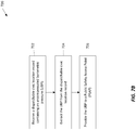
- the gateway 208 in the serving core network 204 is configured to provide the combined UBP and dispatchable civic location to a PSAP.
- the GMLC 306 or the LRF 330 are a means for providing the UBP and the dispatchable civic location to the PSAP.
- the civic location and UBP (e.g. which may both be included within a PIDF-LO) are transferred using HELD, MLP or the J-STD-036 E2 protocol to the PSAP (e.g., the i3 PSAP 344 or the legacy PSAP 348).
- the gateway 208 in the serving core network 204 is configured to extract the UBP from the dispatchable civic location and provide the UBP separately to a PSAP.
- the extracted UBP is transferred to the PSAP using one of HELD, MLP or the J-STD-036 E2 protocol.
- a process 700 for providing UBP to a PSAP without civic location information includes the stages shown.
- the process 700 is, however, an example only and not limiting.
- the process 700 can be altered, e.g., by having stages added, removed, rearranged, combined, and/or performed concurrently.
- UBP information may be obtained by a serving network prior to obtaining the civic location information.
- the process 700 may be executed on one or more computer systems such as depicted in FIG. 9 .
- the serving core network 204 is configured to obtain an uncompensated barometric pressure (UBP) from the UE 100.
- UBP uncompensated barometric pressure
- the pressure sensor 130 in the UE 100 is a means for detecting barometric pressure
- the processor 111 and wireless transceiver 121 are a means for providing the UBP to the serving core network 204.
- the UBP information may be included in an LPPe message transferred (e.g. using LPP/LPPe) between the UE 100 and either (i) an E-SLP 332 or (ii) an E-SMLC 308 (e.g. via the MME 304 and the eNB 302 in the case of an E-SMLC 308).
- the location server 206 (e.g., the E-SMLC 308, E-SLP 332, and/or SAS 354) is a means to obtain UBP from the UE 100.
- the UBP information may be included in a message for (i) LPP (e.g. with the LPP message transferred between the UE 100 and either the E-SLP 332 or the E-SMLC 308, and via the MME 304 and the eNB 302 in the case of the E-SMLC 308), (ii) RRC for LTE (e.g.
- RRC radio resource control
- eNB e.g., a serving eNB like eNB 302 with the serving eNB then using an LPPa message to convey the UBP information to an E-SMLC such as E-SMLC 308) or
- RRC for UMTS e.g. with the RRC message transferred between the UE 100 and a serving RNC like RNC 356 and with the serving RNC then using a PCAP message to convey the UBP information to an SAS such as SAS 354).
- a serving core network 204 is configured to generate a civic location record containing the UBP.
- the serving core network 204 may include a location server 206 such as an E-SMLC 308, E-SLP 332, or SAS 354 as a means to receive civic location information (e.g. one or more civic locations) from the NEAD 212 for UE 100 as previously described and obtain a dispatchable civic location for UE 100 from this civic location information.
- the UBP may be included as a field in a new CA type (e.g., as environmental data, as miscellaneous data or specifically as UBP), or included in an existing civic address type (e.g., type 22 LOC, or type 32 ADDCODE).
- the dispatchable civic location containing the UBP may be included within a PIDF-LO object.
- the location server 206 may be configured to construct an empty civic location record which contains only the UBP.
- the location server 206 is configured to provide the civic location record containing the UBP to a gateway 208.
- the civic location record (containing the UBP) may be part of a PIDF-LO.
- the location server 206 e.g., E-SMLC 308, E-SLP 332, and/or SAS 354 may utilize the existing interfaces and their associated existing protocols (e.g., one or more of the 3GPP SLs, SLg, L0, Lg, Lgd, Iupc, Iu-cs, Iu-ps interfaces) to provide the civic location record containing the UBP (or the PIDF-LO) to the gateway 208 (e.g., the GMLC 306 or LRF 330). Since the UBP information is embedded within the civic location record (which may be futher embedded within a PIDF-LO), the UBP may be transferred and processed transparently through intermediate entities.
- the gateway 208 in the serving core network 204 is configured to extract the UBP from the civic location record.
- the GMLC 306 and/or the LRF 330 are example means for extracting the UBP from the civic location record. Extracting the UBP may be the reverse of the process as described at stage 704. For example, a new CA type containing the UBP, or an existing civic address type containing the UBP may be determined with the UBP extracted by the gateway 208 from this CA type. If a dispatchable civic location was not obtained as part of 704, the gateway 208 may be configured to extract the UBP from an empty civic location record (i.e., empty but for the UBP data).
- the gateway 208 in the serving core network 204 is configured to provide the UBP location to a PSAP (e.g. legacy PSAP 348 or i3 PSAP 344).
- the GMLC 306 or the LRF 330 are a means for providing the UBP to the PSAP.
- the gateway 208 (e.g. GMLC 306 or LRF 330) in the serving core network 204 provides the UBP from the received civic location record to the PSAP (e.g. using a new parameter for HELD, MLP or the J-STD-036 E2 protocol).
- the civic location information may be provided in the same message as the UBP or in one or more separate messages.
- a process 720 for providing UBP to a PSAP with a gateway 208 includes the stages shown.
- the process 720 is, however, an example only and not limiting.
- the process 720 can be altered, e.g., by having stages added, removed, rearranged, combined, and/or performed concurrently.
- the process 720 may be executed on a computer system such as depicted in FIG. 9 .
- the gateway 208 is configured to receive a dispatchable civic location record containing an uncompensated barometric pressure (UBP).
- the location server 206 e.g., E-SMLC 308, E-SLP 332, and/or SAS 354 may utilize the existing interfaces and their associated existing protocols (e.g., one or more of the 3GPP SLs, SLg, L0, Lg, Lgd, Iupc, Iu-cs, Iu-ps interfaces) to provide the civic location record containing the UBP to the gateway 208 (e.g., the GMLC 306 or LRF 330).
- the civic location record may be part of a PIDF-LO.
- the embedded UBP information may be transferred and processed transparently through intermediate entities.
- the gateway 208 is configured to extract the UBP from the dispatchable civic location record.
- the GMLC 306 and/or the LRF 330 are example means for extracting the UBP from the dispatchable civic location record. Extracting the UBP may include, for example, identifying a new CA type, or identifying an existing civic address type and extracting the UBP from information for this CA type.
- the gateway 208 may be configured to extract the UBP from an empty civic location record (i.e., empty but for the UBP data).
- the gateway 208 is configured to provide the UBP to a PSAP (e.g. legacy PSAP 348 or i3 PSAP 344).
- the GMLC 306 or the LRF 330 are a means for providing the UBP to the PSAP.
- the gateway 208 (e.g. GMLC 306 or LRF 330) in the serving core network 204 provides the UBP from the received civic location record (i.e., without the civic location information) to the PSAP (e.g. using a new parameter for HELD, MLP or the J-SRD-036 E2 protocol).
- the civic location information may be provided in the same message as the UBP or in one or more separate messages.
- the gateway 208 does not extract the UBP from the dispatchable civic location record at stage 724 but instead transfers the UBP, still contained within the civic location record, to the PSAP at stage 726.
- a process 730 for providing a dispatchable civic location record containing UBP to a gateway includes the stages shown.
- the process 730 is, however, an example only and not limiting.
- the process 730 can be altered, e.g., by having stages added, removed, rearranged, combined, and/or performed concurrently.
- the process 730 may be executed on a computer system such as depicted in FIG. 9 .
- the location server 206 in a serving core network 204 is configured to obtain an uncompensated barometric pressure (UBP) and location information from the UE 100.
- UBP uncompensated barometric pressure
- the pressure sensor 130 in the UE 100 is a means for detecting barometric pressure
- the processor 111 and wireless transceiver 121 are a means for providing the UBP and the location information to the serving core network 204.
- the location information may comprise one or more MAC addresses for each of one or more WiFi and/or BT APs visible to the UE 100.
- the UBP and the location information may be included in one or more LPPe messages transferred (e.g.
- the location server 206 (e.g., the E-SMLC 308, E-SLP 332, and/or SAS 354) is a means to obtain UBP and location information from the UE 100.
- the UBP and the location information may be included in a message for (i) LPP (e.g.
- RRC for LTE e.g. with the RRC message transferred between UE 100 and a serving eNB like eNB 302 with the serving eNB then using an LPPa message to convey the UBP and location information to an E-SMLC such as E-SMLC 308
- RRC for UMTS e.g. with the RRC message transferred between the UE 100 and a serving RNC like RNC 356 and with the serving RNC then using a PCAP message to convey the UBP and location information to an SAS such as SAS 354
- the location server 206 is configured to obtain a dispatchable civic location for the UE based on the location information obtained at stage 732.
- the location information obtained at stage 732 may include the identities (e.g. MAC addresses) of one or more WiFi and/or BT APs in the WLAN 390 visible to UE 100.
- the location server 206 may provide the NEAD 212 with the AP identities (e.g. MAC addresses). NEAD 212 may then search a database of known WLAN APs for which corresponding civic location information (e.g. a city, street address and/or building designation, floor level and possibly room or apartment number) was previously configured (e.g.
- location server 206 may return to location server 206 one or more civic locations corresponding to each of one or more of the provided AP identities.
- the location server 206 may then obtain a dispatchable civic location (e.g. using one of the civic locations returned by the NEAD 212) as described previously in association with FIG. 2 .
- the location server 206 such as an E-SMLC 308, E-SLP 332, and/or SAS 354 is a means to obtain a dispatchable civic location.
- the location server 206 is configured to combine the UBP with the dispatchable civic location obtained at stage 734 to generate a dispatchable civic location record containing the UBP.
- the UBP may be included as a field in a new CA type (e.g., as environmental data, as miscellaneous data or specifically as UBP), or included in an existing civic address type (e.g., type 22 LOC, or type 32 ADDCODE).
- the location server 206 may be configured to construct an empty civic location record at stage 736 which contains only the UBP.
- the dispatchable civic location record (containing the UBP) may be included as part of a PIDF-LO.
- the location server 206 is configured to provide the civic location record containing the UBP to a gateway 208.
- the civic location record (containing the UBP) may be provided as part of a PIDF-LO.
- the location server 206 e.g., E-SMLC 308, E-SLP 332, and/or SAS 354 may utilize the existing interfaces and associated existing protocols (e.g., one or more of the 3GPP SLs, SLg, L0, Lg, Lgd, Iupc, Iu-cs, Iu-ps interfaces) to provide the civic location record containing the UBP to the gateway 208 (e.g., the GMLC 306 or LRF 330). Since the UBP information is embedded within the civic location record (which may be further embedded within a PDIF-LO), the UBP may be transferred and processed transparently through intermediate entities.
- a UBP may be included within a PIDF-LO using a new or existing parameter or field for a PIDF-LO.
- the UBP may be included within a PIDF-LO but may not be contained or embedded within a dispatchable civic location.
- the PIDF-LO may contain the UBP (e.g. using a new or existing parameter or new or existing field for the PIDF-LO) and may in some cases also contain a dispatchable civic location and/or a geographic location for a UE 100, but where the UBP is part of the PIDF-LO but separate from the dispatchable civic location and/or geographic location.
- the processes 600, 700, 720 and 730 described previously may be used by a serving core network 204 to provide a UBP to a PSAP such as i3 PSAP 344 or legacy PSAP 348 with certain changes.
- a PSAP such as i3 PSAP 344 or legacy PSAP 348 with certain changes.
- stage 602 is performed only as an option;
- the UBP obtained at stage 604 is combined with a PIDF-LO at stage 606 (e.g.
- a PIDF-LO instead of or in addition to a civic location record is generated at stage 704 (e.g. by location server 206) with the PIDF-LO containing the UBP (and any civic location record that was generated);
- the PIDF-LO generated at stage 704 is provided (e.g.
- a PIDF-LO containing a UBP is received at stage 722 by a gateway 208; and (ii) the UBP is extracted from the PIDF-LO at stage 724 by the gateway 208.
- stage 734 is optional and may not always occur; (ii) at stage 736, the UBP obtained at stage 732 is combined (e.g.
- PIDF-LO which may also contain any dispatchable civic location obtained at stage 734 if stage 734 occurs
- the PIDF-LO containing the UBP is provided (e.g. by location server 206) to a gateway (e.g. gateway 208).
- a process 800 for providing UBP to a PSAP via location information messaging includes the stages shown.
- the process 800 is, however, an example only and not limiting.
- the process 800 can be altered, e.g., by having stages added, removed, rearranged, combined, and/or performed concurrently.
- UBP information may be received by a serving network prior to, at the same time as or after determining or receiving location information for a UE.
- the process 800 may be executed on one or more computer systems such as depicted in FIG. 9 .
- the UE 100 and/or location server 206 in the serving core network 204 are configured to determine location information for the UE 100.
- the SPS receiver 155 on the UE 100 processes, in whole or in part, the SPS signals 159 and uses these SPS signals 159 to determine the location of the UE 100.
- the processor 111, memory 140, DSP 112 and/or specialized processor(s) may also be utilized to process the SPS signals 159, in whole or in part, and/or to calculate the location of the UE 100, in conjunction with SPS receiver 155.
- the location server 206 may be used to perform at least part of the location calculation.
- the UE 100 may also estimate its current position within an associated system using various techniques, based on other communication entities within view and/or information available to the UE 100.
- the UE 100 may estimate its position using information obtained from access points (APs) associated with one or more wireless local area networks (WLANs), personal area networks (PANs) utilizing a short-range wireless communication technology such as BLUETOOTH or ZIGBEE®, etc., and/or map constraint data obtained from the location server 206.
- APs access points
- WLANs wireless local area networks
- PANs personal area networks
- a short-range wireless communication technology such as BLUETOOTH or ZIGBEE®, etc.
- the serving core network 204 (e.g. the location server 206) is configured to receive an uncompensated barometric pressure (UBP) from the UE 100.
- UBP uncompensated barometric pressure
- the pressure sensor 130 in the UE 100 is a means for detecting barometric pressure
- the processor 111 and wireless transceiver 121 are a means for providing the UBP to the serving core network 204.
- the UBP information may be included in an LPPe message transferred (e.g. using LPP/LPPe) between the UE 100 and either an E-SLP 332 or an E-SMLC 308 (via the MME 304 and the eNB 302 in the case of E-SMLC 308).
- the location server 206 (e.g., the E-SMLC 308, E-SLP 332, and/or SAS 354) is a means to receive UBP from the UE 100.
- the UBP information may be included in a message for (i) LPP (e.g. with the LPP message transferred between the UE 100 and either the E-SLP 332 or the E-SMLC 308 (via the MME 304 and the eNB 302 in the case of E-SMLC 308)), (ii) RRC for LTE (e.g.
- RRC radio resource control
- eNB e.g., a serving eNB like eNB 302 with the serving eNB then using an LPPa message to convey the UBP information to an E-SMLC such as E-SMLC 308) or
- RRC for UMTS e.g. with the RRC message transferred between the UE 100 and a serving RNC like RNC 356 and with the serving RNC then using a PCAP message to convey the UBP information to an SAS such as SAS 354).
- the location server 206 is configured to combine the UBP with the location information.
- the E-SMLC 308, E-SLP 332, and/or SAS 354 are example means for combining the UBP with the location information.
- the location information may comprise a geographic location and may be represented by an octet string defined in 3GPP TS 23.032.
- the location server 206 may be configured to concatenate, or otherwise combine, several (e.g. two or three) additional octets (e.g. at the end) of a location information octet string to convey the UBP.
- Other methods for combining the UBP with existing location information formats may also be used.
- parameters associated with standard geographic shapes may be modified to accommodate the UBP information (e.g., ellipsoid points, altitude parameters, and XML formats as described above).
- the location server 206 is configured to provide the UBP and location information to the gateway 208.
- the location server 206 e.g., E-SMLC 308, E-SLP 332, and/or SAS 354
- the location server 206 may utilize the existing interfaces and associated existing protocols (e.g., one or more of the 3GPP SLs, SLg, L0, Lg, Lgd, Iupc, Iu-cs, Iu-ps interfaces) to provide the UBP and the location information to the gateway 208 (e.g., the GMLC 306 or LRF 330). Since the UBP information is embedded within the location information, the UBP may be processed transparently through intermediate entities.
- the gateway 208 in the serving core network 204 is configured to extract the UBP from the location information.
- the GMLC 306 and/or the LRF 330 are example means for extracting the UBP from the location information. Extracting the UBP may be the reverse of the process as described at stage 806.
- the gateway 208 may be configured to parse the additional (e.g. two or three) octets from the geographic location string or extract the UBP information from the object formats described above (e.g., ellipsoid points, altitude parameters, and XML tags).
- the gateway 208 in the serving core network 204 is configured to provide the UBP location to a PSAP (e.g. legacy PSAP 348 or i3 PSAP 344).
- the GMLC 306 or the LRF 330 are a means for providing the UBP to the PSAP.
- the gateway 208 (e.g. GMLC 306 or LRF 330) in the serving core network 204 provides the UBP extracted from the location information to the PSAP (e.g. using a new parameter for HELD, MLP or the J-STD-036 E2 protocol).
- the location information may be provided in the same message or in one or more separate messages.
- a location server e.g. E-SMLC 308, E-SLP 332 or SAS 354
- a NEAD e.g. NEAD 212
- a location server 206 may obtain a dispatchable civic location directly from a UE (e.g.
- a location server 206 may obtain a dispatchable civic location from an access network (e.g. eNB 302 or RNC 356 in an access network) or from a WLAN (e.g. from a controller or access point in WLAN 390).
- a location server 206 e.g. E-SMLC 308, E-SLP 332 or SAS 354 may obtain a dispatchable civic location from an access network (e.g. eNB 302 or RNC 356 in an access network) or from a WLAN (e.g. from a controller or access point in WLAN 390).
- a location server 206 e.g.
- E-SMLC 308, E-SLP 332 or SAS 354 may obtain a dispatchable civic location for UE 100 from another location server which may in turn obtain the dispatchable civic location from the NEAD 212, from the UE 100 or from an access network or element in an access network (e.g. eNB 302, Node B 352, or RNC 356) or WLAN (e.g. WLAN 390).
- a location server 206 e.g. E-SMLC 308, E-SLP 332 or SAS 354 may determine a dispatchable civic location itself for the UE 100 (e.g. using data configured in the location server) and possibly based on location related information for the UE 100 (e.g.
- the location server 206 may combine a UBP measurement received from the UE 100 with the dispatchable civic location for UE 100 and transfer the combined dispatchable civic location and UBP to a gateway 208 for either onward transfer to a PSAP or for the gateway to extract the UBP and send the UBP separately to the PSAP.
- FIG. 9 provides a schematic illustration of one embodiment of a computer system 900 that can perform the methods (e.g. as described in association with FIG.s 2-8 ) provided by various other embodiments, as described herein, and/or can function as a mobile device (e.g. UE 100) or other computer system.
- the serving core network 204 may include one or more computer systems 900, such as in location server 206 and the gateway 208.
- the eNB 302, MME 304, GMLC 306, the E-SMLC 308, the E-SLP 332 (including the SPC 334 and the SLC 336), the SAS 354, the LRF 330, and the other entities in FIGS. 3A and 3B may be comprised of one or more computer systems 900.
- FIG. 9 provides a generalized illustration of various components, any or all of which may be utilized as appropriate. FIG. 9 therefore, broadly illustrates how individual system elements may be implemented in a relatively separated or relatively more integrated manner.
- the computer system 900 is shown comprising hardware elements that can be electrically coupled via a bus 905 (or may otherwise be in communication, as appropriate).
- the hardware elements may include one or more processors 910, including without limitation one or more general-purpose processors and/or one or more special-purpose processors (such as digital signal processing chips, graphics acceleration processors, and/or the like); one or more input devices 915, which can include without limitation a mouse, a keyboard and/or the like; and one or more output devices 920, which can include without limitation a display device, a printer and/or the like.
- the processor(s) 910 can include, for example, intelligent hardware devices, e.g., a central processing unit (CPU) such as those made by Intel® Corporation or AMD®, a microcontroller, an ASIC, etc. Other processor types could also be utilized.
- CPU central processing unit
- ASIC application specific integrated circuit
- the computer system 900 may further include (and/or be in communication with) one or more non-transitory storage devices 925, which can comprise, without limitation, local and/or network accessible storage, and/or can include, without limitation, a disk drive, a drive array, an optical storage device, solid-state storage device such as a random access memory (“RAM”) and/or a read-only memory (“ROM”), which can be programmable, flash-updateable and/or the like.
- RAM random access memory
- ROM read-only memory
- Such storage devices may be configured to implement any appropriate data stores, including without limitation, various file systems, database structures, and/or the like.
- the computer system 900 might also include a communications subsystem 930 and a network interface 950, which can include without limitation a modem, a network card (wireless or wired), an infrared communication device, a wireless communication device and/or chipset (such as a BLUETOOTH short-range wireless communication technology transceiver/device, an 802.11 device, a WiFi device, a WiMax device, cellular communication facilities, etc.), and/or the like.
- the network interface 950 may permit data to be exchanged with a network (such as the LTE network described herein, to name one example), other computer systems, and/or any other devices described herein.
- the computer system 900 will further comprise, as here, a working memory 935, which can include a RAM or ROM device, as described above.
- the computer system 900 also can comprise software elements, shown as being currently located within the working memory 935, including an operating system 940, device drivers, executable libraries, and/or other code, such as one or more application programs 945, which may comprise computer programs provided by various embodiments, and/or may be designed to implement methods, and/or configure systems, provided by other embodiments, as described herein.
- application programs 945 may comprise computer programs provided by various embodiments, and/or may be designed to implement methods, and/or configure systems, provided by other embodiments, as described herein.
- one or more processes described herein might be implemented as code and/or instructions executable by a computer (and/or a processor within a computer). Such code and/or instructions can be used to configure and/or adapt a general purpose computer (or other device) to perform one or more operations in accordance with the described methods.
- a set of these instructions and/or code might be stored on a computer-readable storage medium, such as the storage device(s) 925 described above.
- the storage medium might be incorporated within a computer system, such as the computer system 900.
- the storage medium might be separate from a computer system (e.g., a removable medium, such as a compact disc), and/or provided in an installation package, such that the storage medium can be used to program, configure and/or adapt a general purpose computer with the instructions/code stored thereon.
- These instructions might take the form of executable code, which is executable by the computer system 900 and/or might take the form of source and/or installable code, which, upon compilation and/or installation on the computer system 900 (e.g., using any of a variety of generally available compilers, installation programs, compression/decompression utilities, etc.) then takes the form of executable code.
- the computer system 900 may be used to perform methods in accordance with the disclosure. Some or all of the procedures of such methods may be performed by the computer system 900 in response to processor 910 executing one or more sequences of one or more instructions (which might be incorporated into the operating system 940 and/or other code, such as an application programs 945) contained in the working memory 935. Such instructions may be read into the working memory 935 from another computer-readable medium, such as one or more of the storage device(s) 925. Merely by way of example, execution of the sequences of instructions contained in the working memory 935 might cause the processor(s) 910 to perform one or more procedures of the methods described herein.
- machine-readable medium and “computer-readable medium,” as used herein, refer to any medium that participates in providing data that causes a machine to operate in a specific fashion.
- various computer-readable media might be involved in providing instructions/code to processor(s) 111, 910 for execution and/or might be used to store and/or carry such instructions/code (e.g., as signals).
- a computer-readable medium is a physical and/or tangible storage medium. Such a medium may take many forms, including but not limited to, non-volatile media, volatile media, and transmission media.
- Non-volatile media include, for example, optical and/or magnetic disks, such as the storage device(s) 140, 925.
- Volatile media include, without limitation, dynamic memory, such as the working memory 140, 935.
- Transmission media include, without limitation, coaxial cables, copper wire and fiber optics, including the wires that comprise the bus 101, 905, as well as the various components of the communications subsystem 930 (and/or the media by which the communications subsystem 930 provides communication with other devices).
- transmission media can also take the form of waves (including without limitation radio, acoustic and/or light waves, such as those generated during radio-wave and infrared data communications).
- Common forms of physical and/or tangible computer-readable media include, for example, a floppy disk, a flexible disk, hard disk, magnetic tape, or any other magnetic medium, a CD-ROM, a Blu-Ray disc, any other optical medium, punch cards, paper tape, any other physical medium with patterns of holes, a RAM, a PROM, EPROM, a FLASH-EPROM, any other memory chip or cartridge, a carrier wave as described hereinafter, or any other medium from which a computer can read instructions and/or code.
- Various forms of computer-readable media may be involved in carrying one or more sequences of one or more instructions to the processor(s) 111, 910 for execution.
- the instructions may initially be carried on a magnetic disk and/or optical disc of a remote computer.
- a remote computer might load the instructions into its dynamic memory and send the instructions as signals over a transmission medium to be received and/or executed by the UE 100 and/or computer system 900.
- These signals which might be in the form of electromagnetic signals, acoustic signals, optical signals and/or the like, are all examples of carrier waves on which instructions can be encoded, in accordance with various embodiments.
- An example of a non-transitory processor-readable storage medium includes instructions for providing uncompensated barometric pressure information to a PSAP, the instructions including code for obtaining an uncompensated barometric pressure (UBP) from a user equipment, code for obtaining a dispatchable civic location for the user equipment, code for combining the UBP with the dispatchable civic location, and code for sending the UBP and the dispatchable civic location to the PSAP.
- UBP uncompensated barometric pressure
- Implementations of such a non-transitory processor-readable storage medium may include one or more of the following features.
- the location server may be one of an Enhanced Serving Mobile Location Center (E-SMLC), an Emergency SUPL Location Platform (E-SLP), or a Standalone Serving Mobile Location Center (SAS).
- E-SMLC Enhanced Serving Mobile Location Center
- E-SLP Emergency SUPL Location Platform
- SAS Standalone Serving Mobile Location Center
- Code for obtaining the UBP from the user equipment may be configured to obtain the UBP via at least one of a OMA LTE Positioning Protocol Extensions (LPPe) protocol, a 3GPP LTE Positioning Protocol (LPP), a 3GPP Radio Resource Control (RRC) protocol for LTE, a 3GPP RRC protocol for UMTS, a 3GPP LTE Positioning Protocol A (LPPa) protocol or a 3GPP Positioning Calculation Application Part (PCAP) protocol.
- the dispatchable civic location may include a Presence Information Data Format Location Object (PIDF-LO), and the PIDF-LO may be received from a National Emergency Address Database (NEAD).
- PIDF-LO Presence Information Data Format Location Object
- NEAD National Emergency Address Database
- the code for sending the UBP and the dispatchable civic location to the PSAP may include code for providing the UBP and the dispatchable civic location to a gateway via at least one of a 3GPP Iupc, Iu-cs, Iu-ps, SLs, SLg, Lg, Lgd, or L0 interface, and code for providing at least the UBP to the PSAP from the gateway via at least one of a HELD, MLP or J-STD-036 E2 protocol.
- An example of an apparatus for providing uncompensated barometric pressure (UBP) between a user equipment (UE) and a PSAP includes means for determining a location information for the UE, means for receiving the UBP from the UE, means for combining the UBP with the location information, means for providing the UBP and the location information to a gateway, means for extracting the UBP from the location information, and means for providing the UBP to the PSAP.
- UBP uncompensated barometric pressure
- the means for receiving the UBP from the UE may include at least one of a OMA LTE Positioning Protocol Extensions (LPPe) protocol, a 3GPP LTE Positioning Protocol (LPP), a 3GPP Radio Resource Control (RRC) protocol for LTE, a 3GPP RRC protocol for UMTS, a 3GPP LTE Positioning Protocol A (LPPa) protocol or a 3GPP Positioning Calculation Application Part (PCAP) protocol.
- the means for providing the UBP and the location information to the gateway may include at least one of a 3GPP SLs, SLg, L0, Lg, Lgd, Iupc, Iu-cs or Iu-ps interface.
- the means for determining the location information for the UE may include a SPS receiver.
- the means for providing the UBP to the PSAP includes at least one of a HELD, MLP or J-STD-036 E2 protocol.
- the means for combining the UBP with the location information may include concatenating a geographic location string with a data field of several (e.g. two or three) additional octets representing the UBP.
- Configurations may be described as a process which is depicted as a flow diagram or block diagram. Although each may describe the operations as a sequential process, many of the operations can be performed in parallel or concurrently. In addition, the order of the operations may be rearranged. A process may have additional steps not included in the figure.
- examples of the methods may be implemented by hardware, software, firmware, middleware, microcode, hardware description languages, or any combination thereof.
- the program code or code segments to perform the necessary tasks may be stored in a non-transitory computer-readable medium such as a storage medium. Processors may perform the described tasks.
- a statement that a function or operation is "based on" an item or condition means that the function or operation is based on the stated item or condition and may be based on one or more items and/or conditions in addition to the stated item or condition.
Landscapes
- Engineering & Computer Science (AREA)
- Signal Processing (AREA)
- Computer Networks & Wireless Communication (AREA)
- Business, Economics & Management (AREA)
- Emergency Management (AREA)
- Environmental & Geological Engineering (AREA)
- Health & Medical Sciences (AREA)
- Public Health (AREA)
- Human Computer Interaction (AREA)
- Marketing (AREA)
- Mobile Radio Communication Systems (AREA)
- Telephonic Communication Services (AREA)
- Position Fixing By Use Of Radio Waves (AREA)
Applications Claiming Priority (3)
| Application Number | Priority Date | Filing Date | Title |
|---|---|---|---|
| US201562156845P | 2015-05-04 | 2015-05-04 | |
| US14/860,452 US10051684B2 (en) | 2015-05-04 | 2015-09-21 | Transfer of uncompensated barometric pressure information |
| PCT/US2016/025814 WO2016178762A1 (en) | 2015-05-04 | 2016-04-04 | Transfer of uncompensated barometric pressure information |
Publications (2)
| Publication Number | Publication Date |
|---|---|
| EP3292704A1 EP3292704A1 (en) | 2018-03-14 |
| EP3292704B1 true EP3292704B1 (en) | 2021-05-19 |
Family
ID=55809191
Family Applications (1)
| Application Number | Title | Priority Date | Filing Date |
|---|---|---|---|
| EP16718768.1A Active EP3292704B1 (en) | 2015-05-04 | 2016-04-04 | Transfer of uncompensated barometric pressure information |
Country Status (6)
| Country | Link |
|---|---|
| US (1) | US10051684B2 (zh) |
| EP (1) | EP3292704B1 (zh) |
| JP (1) | JP6736582B2 (zh) |
| KR (1) | KR102532718B1 (zh) |
| CN (1) | CN108476375B (zh) |
| WO (1) | WO2016178762A1 (zh) |
Families Citing this family (26)
| Publication number | Priority date | Publication date | Assignee | Title |
|---|---|---|---|---|
| US9838858B2 (en) | 2014-07-08 | 2017-12-05 | Rapidsos, Inc. | System and method for call management |
| WO2017079354A1 (en) | 2015-11-02 | 2017-05-11 | Rapidsos, Inc. | Method and system for situational awareness for emergency response |
| CN108702409A (zh) | 2015-12-17 | 2018-10-23 | 快速求救公司 | 用于有效紧急呼叫的设备和方法 |
| US20170180966A1 (en) * | 2015-12-17 | 2017-06-22 | Rave Wireless, Inc. | Notification of emergencies based on wireless signal recognition |
| US9986404B2 (en) | 2016-02-26 | 2018-05-29 | Rapidsos, Inc. | Systems and methods for emergency communications amongst groups of devices based on shared data |
| JP6919978B2 (ja) | 2016-04-26 | 2021-08-18 | ラピッドエスオーエス,インク. | 緊急通信用のシステムおよび方法 |
| MX2018013813A (es) * | 2016-05-09 | 2019-09-10 | Rapidsos Inc | Sistemas y metodos para comunicaciones de emergencia. |
| US9661127B1 (en) * | 2016-08-02 | 2017-05-23 | Sanjeev Kumar Singh | Locking-out a driver handheld mobile device during driving of a vehicle for texting and browsing |
| US10861320B2 (en) | 2016-08-22 | 2020-12-08 | Rapidsos, Inc. | Predictive analytics for emergency detection and response management |
| EP3651433A1 (en) | 2016-08-26 | 2020-05-13 | Intrinsic Value, LLC | Systems, devices, and methods for emergency responses and safety |
| US10506413B2 (en) | 2017-08-28 | 2019-12-10 | Intrinsic Value, Llc | Systems, devices, and methods for emergency responses and safety |
| US11259165B2 (en) | 2016-08-26 | 2022-02-22 | Intrinsic Value, Llc | Systems, devices, and methods for emergency responses and safety |
| US9992761B2 (en) * | 2016-09-16 | 2018-06-05 | Nextnav, Llc | Systems and methods for transmitting information used to estimate a position of a mobile device |
| US20180206182A1 (en) | 2017-01-18 | 2018-07-19 | Corning Optical Communications Wireless Ltd | Location access units (laus) in a wireless communications system (wcs) for transmitting information to a wireless client device in the wcs for determining location of the client device, and related systems and methods |
| US10187756B1 (en) | 2017-10-19 | 2019-01-22 | 3305978 Nova Scotia Limited | Emergency location informer system |
| EP3721402A4 (en) | 2017-12-05 | 2021-08-04 | Rapidsos Inc. | EMERGENCY MANAGEMENT SOCIAL MEDIA CONTENT |
| US10820181B2 (en) | 2018-02-09 | 2020-10-27 | Rapidsos, Inc. | Emergency location analysis system |
| US10805786B2 (en) | 2018-06-11 | 2020-10-13 | Rapidsos, Inc. | Systems and user interfaces for emergency data integration |
| US11917514B2 (en) | 2018-08-14 | 2024-02-27 | Rapidsos, Inc. | Systems and methods for intelligently managing multimedia for emergency response |
| US10977927B2 (en) | 2018-10-24 | 2021-04-13 | Rapidsos, Inc. | Emergency communication flow management and notification system |
| US11218584B2 (en) | 2019-02-22 | 2022-01-04 | Rapidsos, Inc. | Systems and methods for automated emergency response |
| CA3135274C (en) | 2019-03-29 | 2024-01-16 | Rapidsos, Inc. | Systems and methods for emergency data integration |
| US11146680B2 (en) | 2019-03-29 | 2021-10-12 | Rapidsos, Inc. | Systems and methods for emergency data integration |
| US11228891B2 (en) | 2019-07-03 | 2022-01-18 | Rapidsos, Inc. | Systems and methods for emergency medical communications |
| US11109214B1 (en) * | 2020-08-31 | 2021-08-31 | Motorola Solutions, Inc. | Device, system and method for serving interfaces to client access devices based on assigned roles |
| US11330664B1 (en) | 2020-12-31 | 2022-05-10 | Rapidsos, Inc. | Apparatus and method for obtaining emergency data and providing a map view |
Family Cites Families (19)
| Publication number | Priority date | Publication date | Assignee | Title |
|---|---|---|---|---|
| US8442481B2 (en) * | 2006-05-16 | 2013-05-14 | RedSky Technologies, Inc. | Emergency location information gateway for public safety answering points (PSAPs) and method of use |
| WO2008069712A1 (en) | 2006-12-04 | 2008-06-12 | Telefonaktiebolaget Lm Ericsson (Publ) | Method and arrangement for enhanced cell identification and cell positioning |
| US8254877B2 (en) | 2008-01-04 | 2012-08-28 | Qualcomm Incorporated | Method and apparatus for extended call establishment for IMS emergency calls |
| US9693184B2 (en) | 2008-08-18 | 2017-06-27 | Qualcomm Incorporated | Control plane location solution to support wireless access |
| US8990043B1 (en) | 2011-03-01 | 2015-03-24 | Cellco Partnership | Determining building floor level of wireless mobile communication device |
| WO2013025555A1 (en) | 2011-08-12 | 2013-02-21 | Qualcomm Incorporated | Emergency messaging between citizens and authorities |
| US8787944B2 (en) * | 2011-08-18 | 2014-07-22 | Rivada Research, Llc | Method and system for providing enhanced location based information for wireless handsets |
| US8831556B2 (en) * | 2011-09-30 | 2014-09-09 | Telecommunication Systems, Inc. | Unique global identifier header for minimizing prank emergency 911 calls |
| WO2013184701A1 (en) | 2012-06-05 | 2013-12-12 | Arun Raghupathy | Systems and methods for location positioning of user device |
| US20140162693A1 (en) | 2012-06-15 | 2014-06-12 | Qualcomm Incorporated | Methods and systems for providing location based services in a venue |
| US9439041B2 (en) * | 2012-06-29 | 2016-09-06 | Lighthouse Signal Systems, Llc | Systems and methods for calibration based indoor geolocation |
| US9417313B2 (en) * | 2012-07-18 | 2016-08-16 | Unify Gmbh & Co Kg | Method of conveying a location information representing a physical location of a communication device, a computer program product for executing the method, and the communication device for conveying the location information |
| US9161196B2 (en) * | 2012-08-07 | 2015-10-13 | Google Technology Holdings LLC | Apparatus and method for secure private location information transfer |
| US9078102B2 (en) | 2012-11-12 | 2015-07-07 | Qualcomm Incorporated | Techniques for generating environment and reference data reports for particular environments on behalf of mobile devices |
| US9612114B2 (en) | 2013-01-13 | 2017-04-04 | Qualcomm Incorporated | Access network node based barometric reference pressure network |
| CN103208165A (zh) * | 2013-03-29 | 2013-07-17 | 龚南彬 | 一种安全防护装置和系统 |
| US9998872B2 (en) * | 2014-02-12 | 2018-06-12 | Qualcomm Incorporated | Methods and systems for returning an early positioning fix |
| WO2016025895A1 (en) * | 2014-08-15 | 2016-02-18 | Qualcomm Incorporated | Mobile-assisted determination of the altitude of a mobile device |
| CN104318763B (zh) * | 2014-10-21 | 2016-07-13 | 南京感动科技有限公司 | 多功能感知交通平台系统及其方法 |
-
2015
- 2015-09-21 US US14/860,452 patent/US10051684B2/en active Active
-
2016
- 2016-04-04 WO PCT/US2016/025814 patent/WO2016178762A1/en active Application Filing
- 2016-04-04 EP EP16718768.1A patent/EP3292704B1/en active Active
- 2016-04-04 JP JP2017557294A patent/JP6736582B2/ja active Active
- 2016-04-04 CN CN201680025398.1A patent/CN108476375B/zh active Active
- 2016-04-04 KR KR1020177031779A patent/KR102532718B1/ko active IP Right Grant
Non-Patent Citations (1)
| Title |
|---|
| None * |
Also Published As
| Publication number | Publication date |
|---|---|
| CN108476375A (zh) | 2018-08-31 |
| JP2018519712A (ja) | 2018-07-19 |
| KR20180002649A (ko) | 2018-01-08 |
| US10051684B2 (en) | 2018-08-14 |
| US20160330769A1 (en) | 2016-11-10 |
| WO2016178762A1 (en) | 2016-11-10 |
| CN108476375B (zh) | 2022-03-01 |
| EP3292704A1 (en) | 2018-03-14 |
| KR102532718B1 (ko) | 2023-05-12 |
| JP6736582B2 (ja) | 2020-08-05 |
Similar Documents
| Publication | Publication Date | Title |
|---|---|---|
| EP3292704B1 (en) | Transfer of uncompensated barometric pressure information | |
| US9733337B2 (en) | Support of downlink positioning using coherent and non-coherent signal acquisition | |
| US10278016B2 (en) | Systems and methods for position estimation using proximity devices | |
| US9641984B2 (en) | Support of OTDOA positioning using ambiguous cells | |
| US10194265B2 (en) | Systems and methods for supporting positioning beacons compatible with legacy wireless devices | |
| BR112020014758A2 (pt) | Sistemas e métodos para localização de um equipamento de usuário usando métodos de posição genérica para uma rede 5g | |
| JP2020522167A (ja) | 第5世代ワイヤレスネットワークにおいてモバイルデバイスを測位するためのシステムおよび方法 | |
| KR20160120742A (ko) | 초기 포지셔닝 픽스를 리턴하기 위한 방법들 및 시스템들 | |
| CN116982358A (zh) | 侧链路辅助式定位 | |
| JP2023538741A (ja) | サイドリンク支援測位のための測定値報告 | |
| US20210352610A1 (en) | Efficient positioning enhancement for dynamic spectrum sharing | |
| TW201924422A (zh) | 用於定位協定訊息之分段之方法及系統 | |
| US20170134128A1 (en) | Support of otdoa positioning using mixed transmission port antenna configurations | |
| US20220182785A1 (en) | Systems and methods for civic location determination for mobile devices | |
| KR20230159415A (ko) | 포지셔닝 측정 보고 압축 | |
| CN115885527A (zh) | 使用用于4G和5G的城市位置的增强WiFi定位的方法和装置 | |
| US20180227703A1 (en) | Systems and methods for position estimation using proximity devices |
Legal Events
| Date | Code | Title | Description |
|---|---|---|---|
| STAA | Information on the status of an ep patent application or granted ep patent |
Free format text: STATUS: THE INTERNATIONAL PUBLICATION HAS BEEN MADE |
|
| PUAI | Public reference made under article 153(3) epc to a published international application that has entered the european phase |
Free format text: ORIGINAL CODE: 0009012 |
|
| STAA | Information on the status of an ep patent application or granted ep patent |
Free format text: STATUS: REQUEST FOR EXAMINATION WAS MADE |
|
| 17P | Request for examination filed |
Effective date: 20171005 |
|
| AK | Designated contracting states |
Kind code of ref document: A1 Designated state(s): AL AT BE BG CH CY CZ DE DK EE ES FI FR GB GR HR HU IE IS IT LI LT LU LV MC MK MT NL NO PL PT RO RS SE SI SK SM TR |
|
| AX | Request for extension of the european patent |
Extension state: BA ME |
|
| DAV | Request for validation of the european patent (deleted) | ||
| DAX | Request for extension of the european patent (deleted) | ||
| RIC1 | Information provided on ipc code assigned before grant |
Ipc: H04M 3/51 20060101ALI20161116BHEP Ipc: H04W 4/22 20181130ALI20161116BHEP Ipc: H04W 88/16 20090101ALI20161116BHEP Ipc: H04L 12/66 20060101ALI20161116BHEP Ipc: H04L 29/08 20060101ALI20161116BHEP Ipc: H04L 29/06 20060101ALI20161116BHEP Ipc: H04W 4/02 20180101AFI20161116BHEP |
|
| RIC1 | Information provided on ipc code assigned before grant |
Ipc: H04W 88/16 20090101ALI20161116BHEP Ipc: H04L 29/08 20060101ALI20161116BHEP Ipc: H04L 29/06 20060101ALI20161116BHEP Ipc: H04L 12/66 20060101ALI20161116BHEP Ipc: H04W 4/22 20090101ALI20161116BHEP Ipc: H04W 4/02 20180101AFI20161116BHEP Ipc: H04M 3/51 20060101ALI20161116BHEP |
|
| STAA | Information on the status of an ep patent application or granted ep patent |
Free format text: STATUS: EXAMINATION IS IN PROGRESS |
|
| 17Q | First examination report despatched |
Effective date: 20200518 |
|
| REG | Reference to a national code |
Ref country code: DE Ref legal event code: R079 Ref document number: 602016058021 Country of ref document: DE Free format text: PREVIOUS MAIN CLASS: H04W0004020000 Ipc: H04W0004024000 |
|
| RIC1 | Information provided on ipc code assigned before grant |
Ipc: H04W 4/024 20180101AFI20201007BHEP Ipc: H04W 88/16 20090101ALI20201007BHEP Ipc: H04L 29/06 20060101ALI20201007BHEP Ipc: H04W 4/02 20180101ALI20201007BHEP Ipc: H04L 29/08 20060101ALI20201007BHEP Ipc: H04M 3/51 20060101ALI20201007BHEP Ipc: H04L 12/66 20060101ALI20201007BHEP |
|
| GRAP | Despatch of communication of intention to grant a patent |
Free format text: ORIGINAL CODE: EPIDOSNIGR1 |
|
| STAA | Information on the status of an ep patent application or granted ep patent |
Free format text: STATUS: GRANT OF PATENT IS INTENDED |
|
| INTG | Intention to grant announced |
Effective date: 20201207 |
|
| GRAS | Grant fee paid |
Free format text: ORIGINAL CODE: EPIDOSNIGR3 |
|
| GRAA | (expected) grant |
Free format text: ORIGINAL CODE: 0009210 |
|
| STAA | Information on the status of an ep patent application or granted ep patent |
Free format text: STATUS: THE PATENT HAS BEEN GRANTED |
|
| AK | Designated contracting states |
Kind code of ref document: B1 Designated state(s): AL AT BE BG CH CY CZ DE DK EE ES FI FR GB GR HR HU IE IS IT LI LT LU LV MC MK MT NL NO PL PT RO RS SE SI SK SM TR |
|
| REG | Reference to a national code |
Ref country code: GB Ref legal event code: FG4D |
|
| REG | Reference to a national code |
Ref country code: CH Ref legal event code: EP |
|
| REG | Reference to a national code |
Ref country code: DE Ref legal event code: R096 Ref document number: 602016058021 Country of ref document: DE |
|
| REG | Reference to a national code |
Ref country code: AT Ref legal event code: REF Ref document number: 1395173 Country of ref document: AT Kind code of ref document: T Effective date: 20210615 |
|
| REG | Reference to a national code |
Ref country code: IE Ref legal event code: FG4D |
|
| REG | Reference to a national code |
Ref country code: LT Ref legal event code: MG9D |
|
| REG | Reference to a national code |
Ref country code: AT Ref legal event code: MK05 Ref document number: 1395173 Country of ref document: AT Kind code of ref document: T Effective date: 20210519 |
|
| REG | Reference to a national code |
Ref country code: NL Ref legal event code: MP Effective date: 20210519 |
|
| PG25 | Lapsed in a contracting state [announced via postgrant information from national office to epo] |
Ref country code: LT Free format text: LAPSE BECAUSE OF FAILURE TO SUBMIT A TRANSLATION OF THE DESCRIPTION OR TO PAY THE FEE WITHIN THE PRESCRIBED TIME-LIMIT Effective date: 20210519 Ref country code: FI Free format text: LAPSE BECAUSE OF FAILURE TO SUBMIT A TRANSLATION OF THE DESCRIPTION OR TO PAY THE FEE WITHIN THE PRESCRIBED TIME-LIMIT Effective date: 20210519 Ref country code: AT Free format text: LAPSE BECAUSE OF FAILURE TO SUBMIT A TRANSLATION OF THE DESCRIPTION OR TO PAY THE FEE WITHIN THE PRESCRIBED TIME-LIMIT Effective date: 20210519 Ref country code: BG Free format text: LAPSE BECAUSE OF FAILURE TO SUBMIT A TRANSLATION OF THE DESCRIPTION OR TO PAY THE FEE WITHIN THE PRESCRIBED TIME-LIMIT Effective date: 20210819 Ref country code: HR Free format text: LAPSE BECAUSE OF FAILURE TO SUBMIT A TRANSLATION OF THE DESCRIPTION OR TO PAY THE FEE WITHIN THE PRESCRIBED TIME-LIMIT Effective date: 20210519 |
|
| PG25 | Lapsed in a contracting state [announced via postgrant information from national office to epo] |
Ref country code: PL Free format text: LAPSE BECAUSE OF FAILURE TO SUBMIT A TRANSLATION OF THE DESCRIPTION OR TO PAY THE FEE WITHIN THE PRESCRIBED TIME-LIMIT Effective date: 20210519 Ref country code: PT Free format text: LAPSE BECAUSE OF FAILURE TO SUBMIT A TRANSLATION OF THE DESCRIPTION OR TO PAY THE FEE WITHIN THE PRESCRIBED TIME-LIMIT Effective date: 20210920 Ref country code: NO Free format text: LAPSE BECAUSE OF FAILURE TO SUBMIT A TRANSLATION OF THE DESCRIPTION OR TO PAY THE FEE WITHIN THE PRESCRIBED TIME-LIMIT Effective date: 20210819 Ref country code: RS Free format text: LAPSE BECAUSE OF FAILURE TO SUBMIT A TRANSLATION OF THE DESCRIPTION OR TO PAY THE FEE WITHIN THE PRESCRIBED TIME-LIMIT Effective date: 20210519 Ref country code: SE Free format text: LAPSE BECAUSE OF FAILURE TO SUBMIT A TRANSLATION OF THE DESCRIPTION OR TO PAY THE FEE WITHIN THE PRESCRIBED TIME-LIMIT Effective date: 20210519 Ref country code: GR Free format text: LAPSE BECAUSE OF FAILURE TO SUBMIT A TRANSLATION OF THE DESCRIPTION OR TO PAY THE FEE WITHIN THE PRESCRIBED TIME-LIMIT Effective date: 20210820 Ref country code: IS Free format text: LAPSE BECAUSE OF FAILURE TO SUBMIT A TRANSLATION OF THE DESCRIPTION OR TO PAY THE FEE WITHIN THE PRESCRIBED TIME-LIMIT Effective date: 20210919 Ref country code: LV Free format text: LAPSE BECAUSE OF FAILURE TO SUBMIT A TRANSLATION OF THE DESCRIPTION OR TO PAY THE FEE WITHIN THE PRESCRIBED TIME-LIMIT Effective date: 20210519 |
|
| PG25 | Lapsed in a contracting state [announced via postgrant information from national office to epo] |
Ref country code: NL Free format text: LAPSE BECAUSE OF FAILURE TO SUBMIT A TRANSLATION OF THE DESCRIPTION OR TO PAY THE FEE WITHIN THE PRESCRIBED TIME-LIMIT Effective date: 20210519 |
|
| PG25 | Lapsed in a contracting state [announced via postgrant information from national office to epo] |
Ref country code: SM Free format text: LAPSE BECAUSE OF FAILURE TO SUBMIT A TRANSLATION OF THE DESCRIPTION OR TO PAY THE FEE WITHIN THE PRESCRIBED TIME-LIMIT Effective date: 20210519 Ref country code: SK Free format text: LAPSE BECAUSE OF FAILURE TO SUBMIT A TRANSLATION OF THE DESCRIPTION OR TO PAY THE FEE WITHIN THE PRESCRIBED TIME-LIMIT Effective date: 20210519 Ref country code: EE Free format text: LAPSE BECAUSE OF FAILURE TO SUBMIT A TRANSLATION OF THE DESCRIPTION OR TO PAY THE FEE WITHIN THE PRESCRIBED TIME-LIMIT Effective date: 20210519 Ref country code: CZ Free format text: LAPSE BECAUSE OF FAILURE TO SUBMIT A TRANSLATION OF THE DESCRIPTION OR TO PAY THE FEE WITHIN THE PRESCRIBED TIME-LIMIT Effective date: 20210519 Ref country code: DK Free format text: LAPSE BECAUSE OF FAILURE TO SUBMIT A TRANSLATION OF THE DESCRIPTION OR TO PAY THE FEE WITHIN THE PRESCRIBED TIME-LIMIT Effective date: 20210519 Ref country code: RO Free format text: LAPSE BECAUSE OF FAILURE TO SUBMIT A TRANSLATION OF THE DESCRIPTION OR TO PAY THE FEE WITHIN THE PRESCRIBED TIME-LIMIT Effective date: 20210519 Ref country code: ES Free format text: LAPSE BECAUSE OF FAILURE TO SUBMIT A TRANSLATION OF THE DESCRIPTION OR TO PAY THE FEE WITHIN THE PRESCRIBED TIME-LIMIT Effective date: 20210519 |
|
| REG | Reference to a national code |
Ref country code: DE Ref legal event code: R097 Ref document number: 602016058021 Country of ref document: DE |
|
| PLBE | No opposition filed within time limit |
Free format text: ORIGINAL CODE: 0009261 |
|
| STAA | Information on the status of an ep patent application or granted ep patent |
Free format text: STATUS: NO OPPOSITION FILED WITHIN TIME LIMIT |
|
| 26N | No opposition filed |
Effective date: 20220222 |
|
| PG25 | Lapsed in a contracting state [announced via postgrant information from national office to epo] |
Ref country code: IS Free format text: LAPSE BECAUSE OF FAILURE TO SUBMIT A TRANSLATION OF THE DESCRIPTION OR TO PAY THE FEE WITHIN THE PRESCRIBED TIME-LIMIT Effective date: 20210919 Ref country code: AL Free format text: LAPSE BECAUSE OF FAILURE TO SUBMIT A TRANSLATION OF THE DESCRIPTION OR TO PAY THE FEE WITHIN THE PRESCRIBED TIME-LIMIT Effective date: 20210519 |
|
| PG25 | Lapsed in a contracting state [announced via postgrant information from national office to epo] |
Ref country code: IT Free format text: LAPSE BECAUSE OF FAILURE TO SUBMIT A TRANSLATION OF THE DESCRIPTION OR TO PAY THE FEE WITHIN THE PRESCRIBED TIME-LIMIT Effective date: 20210519 |
|
| REG | Reference to a national code |
Ref country code: CH Ref legal event code: PL |
|
| REG | Reference to a national code |
Ref country code: BE Ref legal event code: MM Effective date: 20220430 |
|
| PG25 | Lapsed in a contracting state [announced via postgrant information from national office to epo] |
Ref country code: MC Free format text: LAPSE BECAUSE OF FAILURE TO SUBMIT A TRANSLATION OF THE DESCRIPTION OR TO PAY THE FEE WITHIN THE PRESCRIBED TIME-LIMIT Effective date: 20210519 Ref country code: LU Free format text: LAPSE BECAUSE OF NON-PAYMENT OF DUE FEES Effective date: 20220404 Ref country code: LI Free format text: LAPSE BECAUSE OF NON-PAYMENT OF DUE FEES Effective date: 20220430 Ref country code: CH Free format text: LAPSE BECAUSE OF NON-PAYMENT OF DUE FEES Effective date: 20220430 |
|
| PG25 | Lapsed in a contracting state [announced via postgrant information from national office to epo] |
Ref country code: BE Free format text: LAPSE BECAUSE OF NON-PAYMENT OF DUE FEES Effective date: 20220430 |
|
| PG25 | Lapsed in a contracting state [announced via postgrant information from national office to epo] |
Ref country code: IE Free format text: LAPSE BECAUSE OF NON-PAYMENT OF DUE FEES Effective date: 20220404 |
|
| PGFP | Annual fee paid to national office [announced via postgrant information from national office to epo] |
Ref country code: FR Payment date: 20230223 Year of fee payment: 8 |
|
| PGFP | Annual fee paid to national office [announced via postgrant information from national office to epo] |
Ref country code: DE Payment date: 20230223 Year of fee payment: 8 |
|
| PG25 | Lapsed in a contracting state [announced via postgrant information from national office to epo] |
Ref country code: HU Free format text: LAPSE BECAUSE OF FAILURE TO SUBMIT A TRANSLATION OF THE DESCRIPTION OR TO PAY THE FEE WITHIN THE PRESCRIBED TIME-LIMIT; INVALID AB INITIO Effective date: 20160404 |
|
| PG25 | Lapsed in a contracting state [announced via postgrant information from national office to epo] |
Ref country code: MK Free format text: LAPSE BECAUSE OF FAILURE TO SUBMIT A TRANSLATION OF THE DESCRIPTION OR TO PAY THE FEE WITHIN THE PRESCRIBED TIME-LIMIT Effective date: 20210519 Ref country code: CY Free format text: LAPSE BECAUSE OF FAILURE TO SUBMIT A TRANSLATION OF THE DESCRIPTION OR TO PAY THE FEE WITHIN THE PRESCRIBED TIME-LIMIT Effective date: 20210519 |
|
| PGFP | Annual fee paid to national office [announced via postgrant information from national office to epo] |
Ref country code: GB Payment date: 20240314 Year of fee payment: 9 |