EP3292307B1 - Schlauchkassette für eine peristaltische pumpe mit elastischen schenkeln - Google Patents
Schlauchkassette für eine peristaltische pumpe mit elastischen schenkeln Download PDFInfo
- Publication number
- EP3292307B1 EP3292307B1 EP17777155.7A EP17777155A EP3292307B1 EP 3292307 B1 EP3292307 B1 EP 3292307B1 EP 17777155 A EP17777155 A EP 17777155A EP 3292307 B1 EP3292307 B1 EP 3292307B1
- Authority
- EP
- European Patent Office
- Prior art keywords
- cassette
- legs
- tube
- pump
- base surface
- Prior art date
- Legal status (The legal status is an assumption and is not a legal conclusion. Google has not performed a legal analysis and makes no representation as to the accuracy of the status listed.)
- Active
Links
Images



Classifications
-
- F—MECHANICAL ENGINEERING; LIGHTING; HEATING; WEAPONS; BLASTING
- F04—POSITIVE - DISPLACEMENT MACHINES FOR LIQUIDS; PUMPS FOR LIQUIDS OR ELASTIC FLUIDS
- F04B—POSITIVE-DISPLACEMENT MACHINES FOR LIQUIDS; PUMPS
- F04B43/00—Machines, pumps, or pumping installations having flexible working members
- F04B43/12—Machines, pumps, or pumping installations having flexible working members having peristaltic action
- F04B43/1253—Machines, pumps, or pumping installations having flexible working members having peristaltic action by using two or more rollers as squeezing elements, the rollers moving on an arc of a circle during squeezing
-
- F—MECHANICAL ENGINEERING; LIGHTING; HEATING; WEAPONS; BLASTING
- F04—POSITIVE - DISPLACEMENT MACHINES FOR LIQUIDS; PUMPS FOR LIQUIDS OR ELASTIC FLUIDS
- F04B—POSITIVE-DISPLACEMENT MACHINES FOR LIQUIDS; PUMPS
- F04B53/00—Component parts, details or accessories not provided for in, or of interest apart from, groups F04B1/00 - F04B23/00 or F04B39/00 - F04B47/00
- F04B53/16—Casings; Cylinders; Cylinder liners or heads; Fluid connections
Definitions
- the present invention relates to an improvement in a peristaltic pump tubing cartridge.
- the hose cassette is U-shaped and made of elastic material, so that the liquid-conveying hose segment can better enclose the roller wheel, whereby the pump power is improved.
- a cassette designed easier and cheaper to produce than prior art cassettes.
- peristaltic peristaltic pumps are commonly used as suction and irrigation pumps, especially in minimally invasive surgery. Such pumps are widely used in arthroscopy, laparoscopy, urology and hysteroscopy. In such applications, of course, ensuring biocompatibility and sterility is of particular importance. Furthermore, the suitability in daily operation is important: in particular the set-up time is of particular importance, d. H. the time medical staff must spend to prepare a fluid pump before use.
- tube cassettes are used for example in the writings EP 1108891 A2 . US 9,289,110 B2 or EP 1820967 A1 described.
- the EP 1820967 A1 describes, for example, a hose cassette with a cassette housing with two frontally arranged fixing elements, wherein between the two fixing a pump tube segment extends, which spans the roller wheel by inserting the cassette into the pump.
- the cassette already contains all tube connections. It can simply be inserted into the opening of the peristaltic pump and is thus ready to use.
- the subject of the invention is therefore a hose cassette with a U-shaped arrangement, with a base and two legs wherein the legs are made of a tough, elastic material, preferably made of a thermoplastic plastic, wherein at the base surface end of the legs per a fixing is fixed in place, wherein at least one pump tube segment between the fixing elements in not inserted in the pump tube cassette along a at least an angle of 120 degrees spanning circle segment runs wherein a fixing each still has at least one hose as a supply line and the second fixing still has at least one hose as a derivative, the legs are connected to each other only at the base and reversibly deformed by bending, so that the distance between the fixing elements during insertion of the Hose cassette can be reversibly changed into a roller wheel pump.
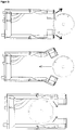
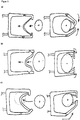
- the special feature of the cassette according to the invention in comparison with the cassettes of the prior art is that the two legs are connected to each other only at the base ( FIG. 1 ). In this way, the legs can move away from each other by spreading apart. This possibility of spreading first facilitates the insertion of the cassette frame in the pump, more precisely: the wrapping of the roller wheel.
- the leg ends eg the fixing elements of the hose cassette according to FIG EP 1820967 A1
- the legs can be spread during insertion, to go back to the original distance in the operating position of the cassette ( FIG. 2 ).
- the distance between the two fixing elements is usually increased by more than 40%, preferably by more than 80%.
- the tube cassette according to the invention which actually only consists of a U-shaped tube cassette frame, less material is required than in a classic cassette, as for example in the EP 1820967 is shown.
- the hose cartridge frame according to the invention consists only of the base and the two legs.
- the cassette is made of a tough, elastic material, preferably of a thermoplastic material, such. As PVC, SBC, PA, PLA, ABS, MABS, PP, PS, PTFE, PET, PE or mixtures of the foregoing. It is crucial that the legs are deformable (eg spreadable), which is ensured by selecting the material and the exact shape.
- the existing at the ends of the U-shaped cassette fixing elements are typically formed as a hollow body, which allow by means of appropriate fittings, the connection of hoses.
- an inflow or drain hose provided at each fixing.
- the pump tube segment is located between the fixing elements.
- the inlet and outlet hoses are of a different material than the pump tube segment.
- the pump tube segment may consist of highly flexible silicone, while the inlet and outlet hoses may consist of relatively inexpensive PVC.
- the sensors or membranes described below may be part of the fixing elements.
- Such fixing elements are for example in the EP1820967 to which reference is hereby made.
- the fixing elements merely fix a hose, so that the pump hose segment is formed between leg ends with the fixing elements. They provide in this way for the tension of the pump tube element in the operating position of the cassette and the necessary reversal of the flow direction of the liquid flow.
- the inner spacing of the fixing elements can be, for example, 5 to 8 cm.
- the legs can be guided around the roller wheel.
- the legs can also be deformed by bending out of the roller wheel plane, as shown in FIG. 6 is pictured. In this case, the legs must have a corresponding deformability.
- the pump hose segment extending between the fixing elements runs along a circular segment and spans at least an angle of 120 degrees, preferably at least 150 degrees, particularly preferably approximately 180 degrees. In special cases, the angle may exceed 180 degrees, e.g. when the fixing elements are compressed in the operating position by corresponding guide elements of the pump.
- the simplified form of the cassette surprisingly also allows a particularly simple production:
- the entire cassette can be manufactured in a single operation as a flat injection-molded part.
- the injection-molded part contains at least two points where the material is formed in the sense of a film hinge, so that it can be folded without breaking to produce the U-shape ("folding cassette", see FIG. 4 ).
- the injection-molded part contains latching devices which enable a latching of parts of the cassette folded into one another in an operational state.
- additional bonds or welds may be made in the region of the folds to increase stability.
- the injection-molded part produced already contains corresponding holes and recesses and guide webs for the hoses. If necessary, an increase in rigidity can be incorporated by means of corresponding shaping elements (eg ribs).
- the fixing can be molded during manufacture by injection molding or 3-D printing. Alternatively, they are made in a separate step and attached to the leg ends. Alternatively, the folding cassette can of course also be produced by 3-D printing.
- the cassette of course in the classical manner in one piece (see FIG. 8 ) or be injected or printed in multiple pieces.
- At least one end face of the fixing element includes a flexible membrane (e.g., silicone, TPE or PVC). This can interact with inserted cartridge with a suitable force / displacement transducer and thus allow pressure measurement.
- a flexible membrane e.g., silicone, TPE or PVC.
- the hose legs can have predetermined breaking points, so that multiple use is not possible.
- the cassette contains information that the pump can read. It is information such as purpose, service or expiration date.
- the corresponding data can be stored on data carriers, for example in the form of a barcode, but also for example by an RFID chip or in another known manner. ever according to memory mode, the information is read out by radio waves or light.
- the cartridge contains a code to prevent multiple use.
- This code can be stored electronically, but also be realized by color or shape design.
- cassettes according to the invention also allow multiple tube segments to be contained in parallel, so that several hose lines can be pumped simultaneously.
- a pump and a cassette according to the invention simultaneously the inflow and outflow from a body cavity can be realized.
- the tube cassette, in particular the fixing elements may also contain other sensors.
- a temperature measurement of the pumping liquid can be carried out by a corresponding temperature sensor.
- the type of liquid and its content of dissolved substances eg salts or sorbitol / mannitol
- the possibility of measuring air bubbles is possible, so that appropriate warnings are possible.
- the measurement of oxygen (O 2 ), or carbon dioxide (CO 2 ) content and / or other parameters is possible by installing appropriate sensors.
- the sensors are largely part of the pump:
- the temperature measurement via an infrared sensor in the pump can be made, provided that the hose cassette has an IR transparent viewing window.
- the cassette may contain two electrodes with corresponding leads. By appropriate contacts on the pump then the electrical parameters can be measured.
- the tube cassette according to the invention can be used for aspirating liquids (water, fat, blood, etc.), but also for flushing body cavities, eg. B. in endoscopy.
- the increased pumping capacity and resistance to back pressure in comparison with conventional roller wheel pumps also improve the widening of body cavities in the context of surgical options.
- the tube cassette according to the invention can also be used in wound therapy be used in the cleaning of wounds. Also in the context of blood circulation (eg in dialysis, blood warming or oxygenation), the cassette can be used.
- the roller wheel pump required for operating the hose cassette can essentially be designed as in the US Pat EP 1820967 A1 described.
- the pump contains, for example, in its housing one, the cartridge complementary cartridge slot. Guiding elements, in particular guide rails, can be helpful here, which first cause the required spreading of the legs during the insertion of the cassette and then the re-merging. Locking elements facilitate holding the cassette in the operating position.
- the sensor elements eg the pressure sensor
- the insertion opening of the housing for the cassette can be form-coded to prevent errors in the introduction of the cassette.
- Figure 7a shows, for example, an alternative embodiment in which the cassette legs do not need to be spread in order to optimally enclose the roller wheel.
- the legs contain articulated sections, so that the leg ends can deform inwards. By pulling the pump tube segment, the leg ends deform with the fixing elements inwards and ensure the necessary enclosure of the roller wheel.
- FIG. 7b shows a similar embodiment with a hinge-like desired deformation of the leg ends.
- the distance between the two fixing elements is usually reduced by more than 30%, preferably by more than 60%, in special cases by more than 80%.
- the mean distance between the ends of the pumping segment A1 50 mm.
- the roller wheel If the cassette is inserted into the pump, the roller wheel with a diameter of 60 mm and a thickness of 24 mm must be overcome.
- the pumping segment In order to produce a high pumping capacity and to ensure the self-sealing effect between roller wheel and pumping segment, the pumping segment must be sufficiently tensioned and the ends of the pumping segment must be at a distance smaller than the roller wheel diameter.
- the cassette is moved relative to the roller wheel along the distance A2 until the axis of the roller wheel with the diameter of 60 mm is at point P1.
- the distance between the cassette and the roller wheel axis A2 47.5 mm.
- the pump segment is thus stretched by about 25% of its length.
Landscapes
- Engineering & Computer Science (AREA)
- Mechanical Engineering (AREA)
- General Engineering & Computer Science (AREA)
- Reciprocating Pumps (AREA)
- External Artificial Organs (AREA)
Description
- Die vorliegende Erfindung betrifft Verbesserung an einer Schlauchkassette für eine peristaltische Pumpe. Die Schlauchkassette ist U-förmig ausgestaltet und aus elastischem Material gefertigt, so dass das flüssigkeitsfördernde Schlauchsegment das Rollenrad besser umschließen kann, womit die Pumpleistung verbessert wird. Erstaunlicherweise ist eine derartig gestaltete Kassette einfacher und preisgünstiger herstellbar als Kassetten des Standes der Technik.
- In der Medizintechnik, werden häufig peristaltische Schlauchpumpen als Saug- und Spülpumpen eingesetzt, insbesondere in der minimalinvasiven Chirurgie. Derartige Pumpen werden häufig in der Arthroskopie, Laparoskopie, Urologie und Hysteroskopie angewandt. Bei derartigen Anwendungen ist naturgemäß die Sicherstellung der Biokompatibilität und der Sterilität von besonderer Bedeutung. Weiterhin ist auch die Tauglichkeit im täglichen Betrieb wichtig: Insbesondere die Rüstzeit ist von besonderer Bedeutung, d. h. die Zeit, die das medizinische Personal aufwenden muss, um eine Flüssigkeitspumpe vor der Anwendung vorzubereiten.
- Zur Vereinfachung der Bedienung derartiger peristaltischer Pumpen hat sich die Verwendung von vorbereiteten Schlauchkassetten etabliert. Derartige Schlauchkassetten werden beispielsweise in den Schriften
EP 1108891 A2 ,US 9,289,110 B2 EP 1820967 A1 beschrieben. DieEP 1820967 A1 beschreibt dabei beispielsweise eine Schlauchkassette mit einem Kassettengehäuse mit zwei stirnseitig angeordneten Fixierelementen, wobei zwischen den beiden Fixierelementen ein Pumpschlauchsegment verläuft, welches durch Einlegen der Kassette in die Pumpe das Rollenrad umspannt. Die Kassette enthält bereits alle Schlauchverbindungen. Sie kann einfach in die Öffnung der Schlauchpumpe eingeschoben werden und ist damit unmittelbar betriebsfertig. - Für verschiedene medizinische Zwecke wäre es wünschenswert, wenn die Pumpleistung einer derartigen Pumpe weiter verbessert werden könnte. Da die Schlauchkassetten als Einwegartikel gebraucht werden, wäre die Verringerung der Herstellungskosten ebenfalls wünschenswert.
- Überraschenderweise hat sich herausgestellt, dass durch die nachfolgend beschriebene verbesserte Schlauchkassette eine verbesserte Pumpleistung erreicht wird, und dass die insoweit beschriebene Schlauchkassette zu geringeren Kosten hergestellt werden kann.
- Gegenstand der Erfindung ist daher eine Schlauchkassette mit U-förmiger Anordnung,
mit einer Basisfläche und zwei Schenkeln
wobei die Schenkel aus einem zähen, elastischem Material, vorzugsweise aus einem thermoplastischen Kunststoff gefertigt sind,
wobei am Basisflächenende der Schenkel je ein Fixierelement ortsfest fixiert ist, wobei mindestens ein Pumpschlauchsegment zwischen den Fixierelementen bei nicht in der Pumpe eingesetzter Schlauchkassette entlang eines zumindest einen Winkel von 120 Grad überspannenden Kreissegmentes verläuft
wobei ein Fixierelemente jeweils noch mindestens einen Schlauch als Zuleitung aufweist und das zweite Fixierelement noch mindestens einen Schlauch als Ableitung aufweist, wobei die Schenkel nur an der Grundfläche miteinander verbunden und durch Biegen reversibel verformbar sind, so dass der Abstand zwischen den Fixierelementen während des Einsetzens der Schlauchkassette in eine Rollenradpumpe reversibel verändert werden kann. - Bevorzugte Ausführungsformen sind Gegenstand der Unteransprüche.
- Das Besondere an der erfindungsgemäßen Kassette im Vergleich zu den Kassetten des Standes der Technik ist, dass die beiden Schenkel nur an der Grundfläche miteinander verbunden sind (
Figur 1 ). Auf diese Weise lassen sich die Schenkel durch Aufspreizen voneinander wegbewegen. Diese Möglichkeit des Aufspreizens erleichtert zunächst das Einsetzen des Kassettenrahmens in die Pumpe, genauer: die Umschlingung des Rollenrades. Bei den Schlauchkassetten gemäß Stand der Technik müssen die Schenkelenden (z. B. die Fixierelemente der Schlauchkassette gemäßEP 1820967 A1 ) einen lichten Abstand voneinander aufweisen, der größer ist, als der Durchmesser des Rollenrades (sieheFigur 4 derEP 1820967 A1 ). Bei der erfindungsgemäßen Schlauchkassette können die Schenkel während des Einführens gespreizt werden, um in Betriebsposition der Kassette wieder auf den ursprünglichen Abstand zurück zu gehen (Figur 2 ). Im Ergebnis wird erreicht, dass der Abstand der beiden Fixierelemente an den Schenkelenden in Betriebsposition kleiner sein kann, als der Durchmesser des Rollenrades. Der Abstand der beiden Fixierelemente voneinander wird dabei üblicherweise um mehr als 40%, bevorzugt um mehr als 80% vergrößert. - Wie sich herausgestellt hat, ist eine derartige Anordnung in Betriebsposition (Abstand der Fixierelemente kleiner als der Durchmesser des Rollenrades) vorteilhaft für die Pumpleistung: Bei der erfindungsgemäßen Rollenradpumpe ist in der dargestellten Betriebsposition der Schlauch an drei Punkten (nämlich den drei Rollenrädern) geschlossen, sodass kein Flüssigkeitsstrom gegen die Bewegung des Rollenrades möglich ist (
Figur 3 unten). Bei der Anordnung gemäß Stand der Technik ist maximal ein Punkt des Schlauches vollständig geschlossen (Figur 3 oben). Im Ergebnis zeigt sich für die erfindungsgemäße Kassette eine höhere Pumpleistung und insbesondere eine größere Widerstandsfähigkeit gegen einen Gegendruck (z. B. bei einem Flüssigkeitsstau). Gleichzeitig wird die Gefahr der Cross-Kontamination durch gegendruckbedingten Rückfluss von Flüssigkeit minimiert. - Für die erfindungsgemäße Schlauchkassette, die eigentlich nur noch aus einem U-förmigen Schlauchkassettenrahmen besteht, wird weniger Material benötigt, als bei einer klassischen Kassette, wie sie beispielsweise in der
EP 1820967 dargestellt ist. Der erfindungsgemäße Schlauchkassettenrahmen besteht lediglich aus der Grundfläche und den beiden Schenkeln. Die Kassette wird aus einem zähen, elastischen Material gefertigt, vorzugsweis aus einem thermoplastischen Kunststoff, wie z. B. PVC, SBC, PA, PLA, ABS, MABS, PP, PS, PTFE, PET, PE oder Mischungen aus den Vorgenannten. Entscheidend ist, dass die Schenkel verformbar (z.B. spreizbar) sind, was durch Auswahl des Materials und der genauen Formgebung gewährleistet wird. - Die an den Enden der U-förmigen Kassette vorhandenen Fixierelemente sind typischerweise als Hohlkörper ausgebildet, die mittels entsprechender Anschlussstücke, den Anschluss von Schläuchen erlauben. An jedem Fixierelement ist dabei beispielsweise ein Zufluss bzw. Abflussschlauch vorgesehen. Zwischen den Fixierelementen ist das Pumpschlauchsegment lokalisiert. Typischerweise sind die Zu- und Abflussschläuche aus einem anderen Material als das Pumpschlauchsegment. Beispielsweise kann das Pumpschlauchsegment aus hochflexiblem Silikon bestehen, während die Zu- und Abflussschläuche aus relativ preiswertem PVC bestehen können.
- Weiterhin können die weiter unten beschriebenen Sensoren bzw. Membranen Bestandteil der Fixierelemente sein. Derartige Fixierelemente sind beispielsweise in der
EP1820967 beschrieben, auf die hiermit inhaltlich verwiesen wird. - Im einfachsten Fall fixieren die Fixierelemente lediglich einen Schlauch, so dass sich zwischen Schenkelenden mit den Fixierelementen das Pumpschlauchsegment ausbildet. Sie sorgen auf diese Weise für die Spannung des Pumpschlauchelementes in Betriebsposition der Kassette und die notwendige Umkehrung der Flussrichtung des Flüssigkeitsstroms.
- Für den Betrieb an der Rollenradpumpe mit einem Rollenraddurchmesser von 8 cm kann der innere Abstand der Fixierelemente beispielsweise 5 - 8 cm betragen. Durch Spreizung der Schenkel können diese um das Rollenrad herumgeführt werden. Alternativ zur Spreizung können die Schenkel auch durch ein Biegen aus der Rollenradebene hinaus verformt werden, so wie es in
Figur 6 dargestellt wird. In diesem Fall müssen die Schenkel eine entsprechende Verformbarkeit aufweisen. - Das zwischen den Fixierelementen verlaufende Pumpschlauchsegment verläuft entlang eines Kreissegmentes und überspannt mindestens einen Winkel von 120 Grad, bevorzugt mindestens 150 Grad, besonders bevorzugt ca. 180 Grad. In Sonderfällen kann der Winkel auch 180 Grad übersteigen, z.B. wenn die Fixierelemente in der Betriebsposition durch entsprechende Führungselemente der Pumpe zusammengedrückt werden.
- Die vereinfachte Form der Kassette erlaubt überraschenderweise auch eine besonders einfache Fertigung:
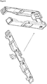
Die gesamte Kassette kann in einem einzigen Arbeitsgang als flaches Spritzgussteil hergestellt werden. Das Spritzgussteil enthält dabei mindestens zwei Stellen, an denen das Material im Sinne eines Filmscharniers ausgebildet ist, so dass es gefaltet werden kann ohne zu brechen, um die U-Form herzustellen ("Faltkassette", sieheFigur 4 ). Ferner enthält das Spritzgussteil Rastvorrichtungen, die ein Einrasten zueinander gefalteten Teile der Kassette in betriebsfertigen Zustand ermöglichen. Gegebenenfalls können im Bereich der Faltstellen zusätzliche Klebungen oder Schweißungen angebracht werden, um die Stabilität zu erhöhen. Vorzugsweise enthält das hergestellte Spritzgussteil bereits entsprechende Löcher und Ausnehmungen sowie Führungsstege für die Schläuche. Bei Bedarf kann eine Erhöhung der Steifigkeit durch entsprechende Formelemente (z. B. Rippen) eingearbeitet werden. - Die Fixierelemente können bei der Herstellung mittels Spritzguss oder 3-D-Druck angeformt werden. Alternativ werden sie in einem separaten Arbeitsschritt hergestellt und auf die Schenkelenden aufgesteckt. Alternativ kann die Faltkassette natürlich auch per 3-D-Druck hergestellt werden.
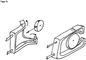
- Weiterhin alternativ kann die Kassette natürlich auch in klassischer Weise einstückig (siehe
Figur 8 ) oder mehrstückig gespritzt oder gedruckt werden. - Durch ein oder mehrere Löcher im Basisteil der Kassette können Zuführschläuche eingeführt und mit dem Fixierelement verbunden werden. Entsprechendes gilt für die Abflussschläuche.
- In einer speziellen Ausführungsform der Kassette enthält mindestens eine Stirnseite des Fixierelementes eine flexible Membran (z.B. aus Silikon, TPE oder PVC). Diese kann bei eingeschobener Kassette mit einem passenden Kraft-/Wegaufnehmer wechselwirken und somit eine Druckmessung ermöglichen.
- In speziellen Ausführungsformen der Schlauchkassette können die Schlauchschenkel Sollbruchstellen aufweisen, so dass eine Mehrfachverwendung nicht möglich ist.
- In besonderen Ausführungsformen der Erfindung enthält die Kassette Informationen, die die Pumpe auslesen kann. Es handelt sich dabei um Informationen, beispielsweise zu Verwendungszweck, Leistung oder Verfalldatum. Die entsprechenden Daten können auf Datenträgern, z.B. in Form eines Barcodes, aber auch beispielsweise durch einen RFID-Chip oder auf andere bekannte Weise gespeichert sein. Je nach Speicherweise erfolgt die Auslesung der Information durch Radiowellen oder Licht.
- In speziellen Ausführungsformen der Erfindung enthält die Kassette einen Code, um Mehrfachbenutzung zu verhindern. Dieser Code kann elektronisch gespeichert sein, aber auch durch Farb- oder Formgestaltung realisiert sein.
- Weiterentwicklungen der erfindungsgemäßen Kassetten erlauben auch mehrere Schlauchsegmente parallel zu enthalten, sodass mehrere Schlauchleitungen gleichzeitig gepumpt werden können. So kann z.B. mittels einer Pumpe und einer erfindungsgemäßen Kassette gleichzeitig der Zufluß und der Abfluß aus einer Körperhöhle realisiert werden.
- Die Schlauchkassette, insbesondere die Fixierelemente können auch weitere Sensoren enthalten. Beispielsweise kann eine Temperaturmessung der Pumpflüssigkeit durch einen entsprechenden Temperatursensor erfolgen. Durch Messung des elektrischen Widerstandes oder der Konduktivität kann die Art der Flüssigkeit und deren Gehalt an gelösten Stoffen (z.B. Salzen oder Sorbitol/Mannitol) gemessen werden. Weiterhin ist die Möglichkeit einer Messung von Luftblasen möglich, sodass entsprechende Warnungen möglich sind. Auch die Messung von Sauerstoff- (O2), bzw. Kohlendioxid-(CO2)-Gehalt und/oder sonstiger Parameter ist durch Einbau entsprechender Sensoren möglich. Vorzugsweise sind die Sensoren weitestgehend Teil der Pumpe: So kann beispielsweise die Temperaturmessung über einen Infrarotsensor in der Pumpe erfolgen, vorausgesetzt die Schlauchkassette weist ein IRdurchlässiges Sichtfenster auf. Für die Messung von Widerstand oder Konduktivität kann die Kassette zwei Elektroden mit entsprechenden Ableitungen enthalten. Durch entsprechende Kontakte an der Pumpe können dann die elektrischen Parameter gemessen werden.
- Die erfindungsgemäße Schlauchkassette kann zum Absaugen von Flüssigkeiten (Wasser, Fett, Blut, etc.) verwendet werden, aber auch zum Spülen von Körperhöhlen, z. B. in der Endoskopie. Durch die erhöhte Pumpleistung und Gegendruckbeständigkeit im Vergleich mit klassischen Rollenradpumpen, ist auch eine Verbesserung des Aufweitens von Körperhöhlen im Rahmen operativer Möglichkeiten gegeben. Die erfindungsgemäße Schlauchkassette kann auch in der Wundtherapie bei der Reinigung von Wunden eingesetzt werden. Auch im Rahmen der Blutzirkulation (z. B. bei der Dialyse, des Blutwärmens oder der Sauerstoffanreicherung) kann die Kassette Verwendung finden.
- Die zum Betrieb der Schlauchkassette erforderliche Rollenradpumpe kann im Wesentlichen so ausgeführt sein wie in der
EP 1820967 A1 beschrieben. Die Pumpe enthält beispielsweise dabei in ihrem Gehäuse eine, der Kassette komplementären Kassettenschacht. Hilfreich können hier Führungselemente, insbesondere Führungsschienen sein, die beim Einschieben der Kassette zunächst die erforderliche Spreizung der Schenkel und anschließend das Wiederzusammenführen bewirken. Rastelemente erleichtern das Halten der Kassette in Betriebsstellung. Selbstverständlich müssen die Sensorelemente (z. B. der Drucksensor) an der Stelle positioniert sein, an der sich die Betriebsstellung die Fixierelemente befinden. Die Einführöffnung des Gehäuses für die Kassette kann dabei formkodiert sein, um Irrtümer bei der Einführung der Kassette zu verhindern. - Die erfindungsgemäße Grundidee kann auch durch alternative Ausführungsformen realisiert werden.
-
Figur 7a zeigt beispielsweise eine alternative Ausführungsform bei der die Kassettenschenkel nicht aufgespreizt werden müssen, um das Rollenrad optimal zu umschließen. In der Ausführungsform gemäßFigur 7a enthalten die Schenkel gelenkartige Abschnitte, so dass sich die Schenkelenden nach innen verformen können. Durch den Zug des Pumpschlauchsegmentes verformen sich die Schenkelenden mit den Fixierelementen nach innen und sorgen für die notwendige Umschließung des Rollenrades. -
Figur 7b ) zeigt eine ähnliche Ausführung mit einer scharnierartigen Sollverformungsstelle der Schenkelenden. - Wie in
Figur 7c schematisch dargestellt ist es unter Umständen möglich nur einen Schenkel verformbar auszugestalten, z.B. bei einer exzentrischen Lage des Rollenrades innerhalb der Kassette (in Betriebsposition). - In diesen Ausführungsarten wird der Abstand der beiden Fixierelemente voneinander üblicherweise um mehr als 30%, bevorzugt um mehr als 60%, in besonderen Fällen um mehr als 80% verkleinert.
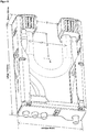
- Ein Ausführungsbeispiel einer erfindungsgemäßen Kassette ist beispielhaft in
Figur 5 abgebildet:
Eine gefaltete Kassette mit den Außenmaße 146x86x30 mm, bestehend aus dem Thermoplast SBC (Styrolux 656c, E-Modul=1800 MPa, Bruchdehnung 20%) mit einer Wandstärke von 1,5 mm. Im unbelasteten Zustand ist der mittlere Abstand zwischen den Enden des Pumpsegmentes A1=50 mm. Das Pumpsegment ist ein Silikonschlauch der Härte 50 Shore A, Länge =160 mm, Außendurchmesser=11 mm und einem Innendurchmesser = 8 mm. Das lichte Maß der Kassettenenden beträgt A3 = 32 mm. - Wird die Kassette in die Pumpe eingelegt, muss das Rollenrad mit einem Durchmesser von 60 mm und einer Dicke von 24 mm überwunden werden. Die Elastizität des Materials und die spezielle Geometrie der Kassette ermöglicht dafür eine Aufspreizung des Kassettenmaßes A3 um mehr als 87%. Hinter dem Rollenrad geht die elastisch verformte Kassette wieder in ihre Ausgangsform zurück (A3 = 32 mm, A1 = 50 mm).
- Um eine hohe Pumpenleistung zu erzeugen und die selbstdichtende Wirkung zwischen Rollenrad und Pumpsegment zu sichern, muss das Pumpsegment ausreichend gespannte werden und die Enden des Pumpsegmentes müssen einen Abstand kleiner dem Rollenraddurchmesser haben. Hierfür wird die Kassette relativ zum Rollenrad entlang der Strecke A2 weiter verschoben, bis sich die Achse des Rollenrades mit dem Durchmesser von 60 mm im Punkt P1 befindet. In der gespannten Endlage beträgt der Abstand zwischen Kassette und der Rollenradachse A2 = 47,5 mm. Das Pumpsegment wird somit um ca. 25% seiner Länge gedehnt. Die Enden der Kassette werden weiterhin gestützt, um das Maß A3 = 32 mm zu fixieren. Damit bleibt auch der mittlere Abstand der Enden des Pumpsegmentes A1 = 50 mm dauerhaft kleiner als der Rollenraddurchmesser von 60 mm (hier rund 17% kleiner).
Claims (9)
- Schlauchkassette mit U-förmiger Anordnung zur Verwendung in einer Rollenradpumpe,
mit einer Basisfläche und zwei Schenkeln
wobei die Schenkel aus einem zähen, elastischem Material gefertigt sind, wobei am Basisflächenende der Schenkel je ein Fixierelement ortsfest fixiert ist,
wobei mindestens ein Zuflußschlauch im Wesentlichen parallel zu einem ersten Schenkel zum ersten Fixierelement verläuft,
wobei mindestens ein Abflußschlauch im Wesentlichen parallel zu einem zweiten Schenkel vom zweiten Fixierelement weg verläuft,
wobei mindestens ein Pumpschlauchsegment zwischen den Fixierelementen bei nicht in der Pumpe eingesetzter Schlauchkassette entlang eines zumindest einen Winkel von 120 Grad überspannenden Kreissegmentes verläuft,
dadurch gekennzeichnet, dass
die Schenkel nur an der Basisfläche miteinander verbunden und durch Biegen reversibel verformbar sind, so dass der Abstand zwischen den Fixierelementen während des Einsetzens der Schlauchkassette in die Rollenradpumpe reversibel um mehr als 40% vergrößert oder um mehr als 30% verkleinert werden kann. - Schlauchkassette gemäß Anspruch 1, dadurch gekennzeichnet, dass die Kassette aus einem thermoplastischen Kunststoff, wie z. B. PVC, SBC, PA, PC, PLA, ABS, MABS, PP, PS, PTFE, PET, PE oder Mischungen aus den Vorgenannten gefertigt ist.
- Schlauchkassette gemäß Anspruch 1, dadurch gekennzeichnet, dass die Schenkel durch Biegen entwedera) reversibel aufgespreizt werden,b) reversibel zusammengedrückt werden oderc) reversibel aus der Ebene des Rollenrades heraus verformt werden können.
- Schlauchkassette gemäß Anspruch 1, gekennzeichnet, durch ein oder mehrere Sensoren zur Messung von Parametern der gepumpten Flüssigkeit.
- Schlauchkassette gemäß Anspruch 4, gekennzeichnet, durch ein oder mehrere Sensoren zur Messung Druck, Temperatur, Flüssigkeitsstrom, Widerstand, Konduktivität, O2-Gehalt, CO2-Gehalt, Salzgehalt und/oder Gasblasen.
- Schlauchkassette gemäß Anspruch 1, dadurch gekennzeichnet, dass mindestens ein Fixierelement eine flexible Membran zur Druckmessung aufweist.
- Schlauchkassette gemäß Anspruch 1, dadurch gekennzeichnet, dass in oder auf der Kassette Informationen auf Datenträgern gespeichert sind.
- Verfahren zur Herstellung einer Schlauchkassette mit U-förmiger Anordnung, mit einer Basisfläche und zwei Schenkeln
wobei die Schenkel aus einem zähen, elastischem Material gefertigt sind, wobei am Basisflächenende der Schenkel je ein Fixierelement ortsfest fixiert ist,
wobei mindestens ein Zuflußschlauch im Wesentlichen parallel zu einem ersten Schenkel zum ersten Fixierelement verläuft,
wobei mindestens ein Abflußschlauch im Wesentlichen parallel zu einem zweiten Schenkel vom zweiten Fixierelement weg verläuft, wobei mindestens ein Pumpschlauchsegment zwischen den Fixierelementen bei nicht in der Pumpe eingesetzter Schlauchkassette entlang eines zumindest einen Winkel von 120 Grad überspannenden Kreissegmentes verläuft,
wobei die Schenkel nur an der Basisfläche miteinander verbunden und durch Biegen reversibel verformbar sind, so dass der Abstand zwischen den Fixierelementen während des Einsetzens der Schlauchkassette in die Rollenradpumpe reversibel um mehr als 40% vergrößert oder um mehr als 30% verkleinert werden kann
mit folgenden Verfahrensschrittena) Herstellung eines im Wesentlichen flachen Spritzgußteils aus einem zähen, elastischem Material, vorzugsweise aus einem thermoplastischen Kunststoff mit mindestens zwei Filmscharnieren sowie mehreren Rastelementen,b) Falten des Spritzgußteils an den Filmscharnieren,c) Einrasten der Schenkel an Rastelementen der Basisfläched) Montage von zwei Fixierelementen,e) Anbringen der Schläuche an den Fixierelementen. - Verfahren gemäß Anspruch 8, wobei das Material für die Fertigung der Schenkel thermoplastischer Kunststoff, wie z.B. PVC, SBC, PA, PC, PLA, ABS, MABS, PP, PS, PTFE, PET, PE oder Mischungen aus den Vorgenannten ist.
Applications Claiming Priority (2)
| Application Number | Priority Date | Filing Date | Title |
|---|---|---|---|
| DE102016009174.6A DE102016009174B3 (de) | 2016-07-29 | 2016-07-29 | Schlauchkassette für eine peristaltische Pumpe mit elastischen Schenkeln |
| PCT/DE2017/000226 WO2018019320A1 (de) | 2016-07-29 | 2017-07-27 | Schlauchkassette für eine peristaltische pumpe mit elastischen schenkeln |
Publications (2)
| Publication Number | Publication Date |
|---|---|
| EP3292307A1 EP3292307A1 (de) | 2018-03-14 |
| EP3292307B1 true EP3292307B1 (de) | 2019-02-27 |
Family
ID=59982219
Family Applications (1)
| Application Number | Title | Priority Date | Filing Date |
|---|---|---|---|
| EP17777155.7A Active EP3292307B1 (de) | 2016-07-29 | 2017-07-27 | Schlauchkassette für eine peristaltische pumpe mit elastischen schenkeln |
Country Status (7)
| Country | Link |
|---|---|
| US (1) | US11098706B2 (de) |
| EP (1) | EP3292307B1 (de) |
| JP (1) | JP7220566B2 (de) |
| CN (1) | CN107923384B (de) |
| DE (1) | DE102016009174B3 (de) |
| ES (1) | ES2728068T3 (de) |
| WO (1) | WO2018019320A1 (de) |
Family Cites Families (20)
| Publication number | Priority date | Publication date | Assignee | Title |
|---|---|---|---|---|
| JPH0272380U (de) * | 1988-11-17 | 1990-06-01 | ||
| US4904168A (en) * | 1988-12-28 | 1990-02-27 | United Sonics, Inc. | Cassette assembly for ophthalmic surgery system |
| FR2677711B1 (fr) * | 1991-06-12 | 1993-10-08 | Smh Management Services Ag | Pompe peristaltique. |
| US5257917A (en) * | 1992-10-02 | 1993-11-02 | Cole-Parmer Instrument Company | Peristaltic pump having means for reducing flow pulsation |
| US5403277A (en) * | 1993-01-12 | 1995-04-04 | Minnesota Mining And Manufacturing Company | Irrigation system with tubing cassette |
| DE59405906D1 (de) * | 1994-02-16 | 1998-06-10 | Stoeckert Instr Gmbh | Schlauchfixierungsvorrichtung für Rollenpumpen |
| JPH0960593A (ja) * | 1995-08-25 | 1997-03-04 | Mazda Motor Corp | チューブ押圧式ポンプ |
| DE19960668C1 (de) * | 1999-12-15 | 2001-08-16 | W O M Gmbh Physikalisch Medizi | Schlauchkasette für eine peristaltische Pumpe |
| DE10244090A1 (de) | 2002-09-23 | 2004-04-01 | Ismatec S.A. | Schlauchkassette für eine peristaltische Pumpe |
| EP1680600B1 (de) * | 2003-09-26 | 2007-12-19 | Ismatec SA, Laboratoriumstechnik | Peristaltische pumpe |
| JP2006002659A (ja) * | 2004-06-17 | 2006-01-05 | Seiko Epson Corp | チューブポンプおよび液体吐出装置 |
| DE102006008325B4 (de) * | 2006-02-20 | 2013-09-12 | W.O.M. World Of Medicine Ag | Schlauchkassette für eine peristaltische Pumpe |
| US7841647B2 (en) * | 2006-11-15 | 2010-11-30 | Sika Technology Ag | Baffle assembly |
| US8366655B2 (en) * | 2007-02-27 | 2013-02-05 | Deka Products Limited Partnership | Peritoneal dialysis sensor apparatus systems, devices and methods |
| ITBO20080152A1 (it) * | 2008-03-07 | 2009-09-08 | Carpigiani Group Ali Spa | Pompa peristaltica. |
| JP5397747B2 (ja) * | 2009-02-16 | 2014-01-22 | ニプロ株式会社 | チューブポンプ |
| JP2012057526A (ja) | 2010-09-08 | 2012-03-22 | Sii Printek Inc | チューブポンプ及びそれを備えた液体噴射記録装置 |
| EP2441483A1 (de) | 2010-10-13 | 2012-04-18 | Fresenius Kabi Deutschland GmbH | Pumpenmodul, Pumpenbasismodul und Pumpenssystem |
| US9289110B2 (en) * | 2012-04-05 | 2016-03-22 | Stryker Corporation | Control for surgical fluid management pump system |
| DE102012108052A1 (de) * | 2012-08-30 | 2014-03-06 | Aesculap Ag | Schlauchaufnahme einer Rollerpumpe |
-
2016
- 2016-07-29 DE DE102016009174.6A patent/DE102016009174B3/de not_active Expired - Fee Related
-
2017
- 2017-07-27 ES ES17777155T patent/ES2728068T3/es active Active
- 2017-07-27 EP EP17777155.7A patent/EP3292307B1/de active Active
- 2017-07-27 US US15/752,092 patent/US11098706B2/en active Active
- 2017-07-27 JP JP2018563829A patent/JP7220566B2/ja active Active
- 2017-07-27 CN CN201780002870.4A patent/CN107923384B/zh active Active
- 2017-07-27 WO PCT/DE2017/000226 patent/WO2018019320A1/de not_active Ceased
Non-Patent Citations (1)
| Title |
|---|
| None * |
Also Published As
| Publication number | Publication date |
|---|---|
| ES2728068T3 (es) | 2019-10-22 |
| CN107923384A (zh) | 2018-04-17 |
| JP7220566B2 (ja) | 2023-02-10 |
| DE102016009174B3 (de) | 2017-11-02 |
| EP3292307A1 (de) | 2018-03-14 |
| US20180238318A1 (en) | 2018-08-23 |
| US11098706B2 (en) | 2021-08-24 |
| JP2019523359A (ja) | 2019-08-22 |
| CN107923384B (zh) | 2019-12-06 |
| WO2018019320A1 (de) | 2018-02-01 |
Similar Documents
| Publication | Publication Date | Title |
|---|---|---|
| DE10008826C2 (de) | Mikroperfusionsvorrichtung mit Sammelbehältnis | |
| DE69020558T2 (de) | Blutpumpe. | |
| DE69131043T2 (de) | Ventilsystem mit abnehmbarem fluidtrennkörper | |
| EP2536448B1 (de) | Kopplungsteil einer drainageschlaucheinheit | |
| DE112010004977B4 (de) | Radial komprimierbarer und expandierbarer Rotor für eine Fluidpumpe | |
| DE3785444T2 (de) | Tubussatz für die Arthroscopie-Spülung. | |
| EP1061978B1 (de) | Injektor zur applizierung von flüssigkeiten, insbesondere von kontrastmitteln für die röntgen- und kernspintomographie | |
| DE112011100345T5 (de) | Fördereinrichtung für ein Fluid | |
| EP2665934B1 (de) | Kolbenpumpe; vorrichtung zur zuführung und dosierung eines fluids für medizinische zwecke mittels kolbenpumpe | |
| DE3620743A1 (de) | Einrichtung zur verwendung mit fluessigkeitsuebertragungsgeraeten | |
| EP3266484A1 (de) | Vorrichtung zur anfeuchtung von atemgas | |
| EP3363492B1 (de) | Nadelmodul für eine antriebsgesteuerte vorrichtung zum wiederholten aufstechen einer menschlichen oder einer tierischen haut und handgerät | |
| EP2714249B1 (de) | Vorrichtung für den stoff- und/oder energieaustausch zwischen zwei medien | |
| DE102016009174B3 (de) | Schlauchkassette für eine peristaltische Pumpe mit elastischen Schenkeln | |
| WO2021074371A1 (de) | FÜHRUNGSELEMENT FÜR EIN STEUERBARES GEFÄßAUFWEITUNGSSYSTEM UND STEUERBARES GEFÄßAUFWEITUNGSSYSTEM | |
| DE4018723C1 (de) | ||
| EP2751428B1 (de) | Pumpenschlauch für eine peristaltische pumpe | |
| EP2679255B1 (de) | Pumpsystem, Schlauchpumpe und Schlauchkassette sowie Verfahren zum Konfigurieren eines Pumpsystems | |
| WO2014135458A1 (de) | Vorrichtung zur regulation eines volumenstroms | |
| DE102019131369A1 (de) | Oxygenatorvorrichtung | |
| DE102010005135A1 (de) | Vorrichtung für den Stoff- und/oder Energieaustausch zwischen zwei Medien | |
| DE202011102929U1 (de) | Fluidtank zum Zu- und Abführen eines Fluids zu und von einem medizinischen Saug- und Spülinstrument | |
| EP4572662A1 (de) | Verfahren und vorrichtung zur nicht-invasiven blutdruckmessung sowie gehäuse | |
| DE69704630T2 (de) | Medizinische aspirations- oder insufflationsvorrichtung mit absperrventil | |
| DE3106611A1 (de) | "medizinische infusionsvorrichtung, insbesondere auswechselbare pumpen-kassette dafuer" |
Legal Events
| Date | Code | Title | Description |
|---|---|---|---|
| STAA | Information on the status of an ep patent application or granted ep patent |
Free format text: STATUS: UNKNOWN |
|
| STAA | Information on the status of an ep patent application or granted ep patent |
Free format text: STATUS: THE INTERNATIONAL PUBLICATION HAS BEEN MADE |
|
| PUAI | Public reference made under article 153(3) epc to a published international application that has entered the european phase |
Free format text: ORIGINAL CODE: 0009012 |
|
| STAA | Information on the status of an ep patent application or granted ep patent |
Free format text: STATUS: REQUEST FOR EXAMINATION WAS MADE |
|
| 17P | Request for examination filed |
Effective date: 20171123 |
|
| AK | Designated contracting states |
Kind code of ref document: A1 Designated state(s): AL AT BE BG CH CY CZ DE DK EE ES FI FR GB GR HR HU IE IS IT LI LT LU LV MC MK MT NL NO PL PT RO RS SE SI SK SM TR |
|
| AX | Request for extension of the european patent |
Extension state: BA ME |
|
| GRAP | Despatch of communication of intention to grant a patent |
Free format text: ORIGINAL CODE: EPIDOSNIGR1 |
|
| STAA | Information on the status of an ep patent application or granted ep patent |
Free format text: STATUS: GRANT OF PATENT IS INTENDED |
|
| DAV | Request for validation of the european patent (deleted) | ||
| DAX | Request for extension of the european patent (deleted) | ||
| INTG | Intention to grant announced |
Effective date: 20181130 |
|
| GRAS | Grant fee paid |
Free format text: ORIGINAL CODE: EPIDOSNIGR3 |
|
| GRAA | (expected) grant |
Free format text: ORIGINAL CODE: 0009210 |
|
| STAA | Information on the status of an ep patent application or granted ep patent |
Free format text: STATUS: THE PATENT HAS BEEN GRANTED |
|
| AK | Designated contracting states |
Kind code of ref document: B1 Designated state(s): AL AT BE BG CH CY CZ DE DK EE ES FI FR GB GR HR HU IE IS IT LI LT LU LV MC MK MT NL NO PL PT RO RS SE SI SK SM TR |
|
| REG | Reference to a national code |
Ref country code: GB Ref legal event code: FG4D Free format text: NOT ENGLISH |
|
| REG | Reference to a national code |
Ref country code: CH Ref legal event code: EP |
|
| REG | Reference to a national code |
Ref country code: AT Ref legal event code: REF Ref document number: 1101759 Country of ref document: AT Kind code of ref document: T Effective date: 20190315 |
|
| REG | Reference to a national code |
Ref country code: IE Ref legal event code: FG4D Free format text: LANGUAGE OF EP DOCUMENT: GERMAN |
|
| REG | Reference to a national code |
Ref country code: DE Ref legal event code: R096 Ref document number: 502017000838 Country of ref document: DE |
|
| REG | Reference to a national code |
Ref country code: NL Ref legal event code: MP Effective date: 20190227 |
|
| REG | Reference to a national code |
Ref country code: LT Ref legal event code: MG4D |
|
| PG25 | Lapsed in a contracting state [announced via postgrant information from national office to epo] |
Ref country code: SE Free format text: LAPSE BECAUSE OF FAILURE TO SUBMIT A TRANSLATION OF THE DESCRIPTION OR TO PAY THE FEE WITHIN THE PRESCRIBED TIME-LIMIT Effective date: 20190227 Ref country code: NL Free format text: LAPSE BECAUSE OF FAILURE TO SUBMIT A TRANSLATION OF THE DESCRIPTION OR TO PAY THE FEE WITHIN THE PRESCRIBED TIME-LIMIT Effective date: 20190227 Ref country code: NO Free format text: LAPSE BECAUSE OF FAILURE TO SUBMIT A TRANSLATION OF THE DESCRIPTION OR TO PAY THE FEE WITHIN THE PRESCRIBED TIME-LIMIT Effective date: 20190527 Ref country code: PT Free format text: LAPSE BECAUSE OF FAILURE TO SUBMIT A TRANSLATION OF THE DESCRIPTION OR TO PAY THE FEE WITHIN THE PRESCRIBED TIME-LIMIT Effective date: 20190627 Ref country code: LT Free format text: LAPSE BECAUSE OF FAILURE TO SUBMIT A TRANSLATION OF THE DESCRIPTION OR TO PAY THE FEE WITHIN THE PRESCRIBED TIME-LIMIT Effective date: 20190227 Ref country code: FI Free format text: LAPSE BECAUSE OF FAILURE TO SUBMIT A TRANSLATION OF THE DESCRIPTION OR TO PAY THE FEE WITHIN THE PRESCRIBED TIME-LIMIT Effective date: 20190227 |
|
| PG25 | Lapsed in a contracting state [announced via postgrant information from national office to epo] |
Ref country code: IS Free format text: LAPSE BECAUSE OF FAILURE TO SUBMIT A TRANSLATION OF THE DESCRIPTION OR TO PAY THE FEE WITHIN THE PRESCRIBED TIME-LIMIT Effective date: 20190627 Ref country code: HR Free format text: LAPSE BECAUSE OF FAILURE TO SUBMIT A TRANSLATION OF THE DESCRIPTION OR TO PAY THE FEE WITHIN THE PRESCRIBED TIME-LIMIT Effective date: 20190227 Ref country code: RS Free format text: LAPSE BECAUSE OF FAILURE TO SUBMIT A TRANSLATION OF THE DESCRIPTION OR TO PAY THE FEE WITHIN THE PRESCRIBED TIME-LIMIT Effective date: 20190227 Ref country code: GR Free format text: LAPSE BECAUSE OF FAILURE TO SUBMIT A TRANSLATION OF THE DESCRIPTION OR TO PAY THE FEE WITHIN THE PRESCRIBED TIME-LIMIT Effective date: 20190528 Ref country code: BG Free format text: LAPSE BECAUSE OF FAILURE TO SUBMIT A TRANSLATION OF THE DESCRIPTION OR TO PAY THE FEE WITHIN THE PRESCRIBED TIME-LIMIT Effective date: 20190527 Ref country code: LV Free format text: LAPSE BECAUSE OF FAILURE TO SUBMIT A TRANSLATION OF THE DESCRIPTION OR TO PAY THE FEE WITHIN THE PRESCRIBED TIME-LIMIT Effective date: 20190227 |
|
| REG | Reference to a national code |
Ref country code: ES Ref legal event code: FG2A Ref document number: 2728068 Country of ref document: ES Kind code of ref document: T3 Effective date: 20191022 |
|
| PG25 | Lapsed in a contracting state [announced via postgrant information from national office to epo] |
Ref country code: CZ Free format text: LAPSE BECAUSE OF FAILURE TO SUBMIT A TRANSLATION OF THE DESCRIPTION OR TO PAY THE FEE WITHIN THE PRESCRIBED TIME-LIMIT Effective date: 20190227 Ref country code: RO Free format text: LAPSE BECAUSE OF FAILURE TO SUBMIT A TRANSLATION OF THE DESCRIPTION OR TO PAY THE FEE WITHIN THE PRESCRIBED TIME-LIMIT Effective date: 20190227 Ref country code: EE Free format text: LAPSE BECAUSE OF FAILURE TO SUBMIT A TRANSLATION OF THE DESCRIPTION OR TO PAY THE FEE WITHIN THE PRESCRIBED TIME-LIMIT Effective date: 20190227 Ref country code: DK Free format text: LAPSE BECAUSE OF FAILURE TO SUBMIT A TRANSLATION OF THE DESCRIPTION OR TO PAY THE FEE WITHIN THE PRESCRIBED TIME-LIMIT Effective date: 20190227 Ref country code: AL Free format text: LAPSE BECAUSE OF FAILURE TO SUBMIT A TRANSLATION OF THE DESCRIPTION OR TO PAY THE FEE WITHIN THE PRESCRIBED TIME-LIMIT Effective date: 20190227 Ref country code: SK Free format text: LAPSE BECAUSE OF FAILURE TO SUBMIT A TRANSLATION OF THE DESCRIPTION OR TO PAY THE FEE WITHIN THE PRESCRIBED TIME-LIMIT Effective date: 20190227 |
|
| REG | Reference to a national code |
Ref country code: DE Ref legal event code: R097 Ref document number: 502017000838 Country of ref document: DE |
|
| PG25 | Lapsed in a contracting state [announced via postgrant information from national office to epo] |
Ref country code: PL Free format text: LAPSE BECAUSE OF FAILURE TO SUBMIT A TRANSLATION OF THE DESCRIPTION OR TO PAY THE FEE WITHIN THE PRESCRIBED TIME-LIMIT Effective date: 20190227 Ref country code: SM Free format text: LAPSE BECAUSE OF FAILURE TO SUBMIT A TRANSLATION OF THE DESCRIPTION OR TO PAY THE FEE WITHIN THE PRESCRIBED TIME-LIMIT Effective date: 20190227 |
|
| PLBE | No opposition filed within time limit |
Free format text: ORIGINAL CODE: 0009261 |
|
| STAA | Information on the status of an ep patent application or granted ep patent |
Free format text: STATUS: NO OPPOSITION FILED WITHIN TIME LIMIT |
|
| 26N | No opposition filed |
Effective date: 20191128 |
|
| PG25 | Lapsed in a contracting state [announced via postgrant information from national office to epo] |
Ref country code: SI Free format text: LAPSE BECAUSE OF FAILURE TO SUBMIT A TRANSLATION OF THE DESCRIPTION OR TO PAY THE FEE WITHIN THE PRESCRIBED TIME-LIMIT Effective date: 20190227 Ref country code: MC Free format text: LAPSE BECAUSE OF FAILURE TO SUBMIT A TRANSLATION OF THE DESCRIPTION OR TO PAY THE FEE WITHIN THE PRESCRIBED TIME-LIMIT Effective date: 20190227 |
|
| PG25 | Lapsed in a contracting state [announced via postgrant information from national office to epo] |
Ref country code: TR Free format text: LAPSE BECAUSE OF FAILURE TO SUBMIT A TRANSLATION OF THE DESCRIPTION OR TO PAY THE FEE WITHIN THE PRESCRIBED TIME-LIMIT Effective date: 20190227 |
|
| REG | Reference to a national code |
Ref country code: BE Ref legal event code: MM Effective date: 20190731 |
|
| PG25 | Lapsed in a contracting state [announced via postgrant information from national office to epo] |
Ref country code: LU Free format text: LAPSE BECAUSE OF NON-PAYMENT OF DUE FEES Effective date: 20190727 Ref country code: BE Free format text: LAPSE BECAUSE OF NON-PAYMENT OF DUE FEES Effective date: 20190731 |
|
| PG25 | Lapsed in a contracting state [announced via postgrant information from national office to epo] |
Ref country code: IE Free format text: LAPSE BECAUSE OF NON-PAYMENT OF DUE FEES Effective date: 20190727 |
|
| REG | Reference to a national code |
Ref country code: CH Ref legal event code: PL |
|
| PG25 | Lapsed in a contracting state [announced via postgrant information from national office to epo] |
Ref country code: LI Free format text: LAPSE BECAUSE OF NON-PAYMENT OF DUE FEES Effective date: 20200731 Ref country code: CH Free format text: LAPSE BECAUSE OF NON-PAYMENT OF DUE FEES Effective date: 20200731 |
|
| PG25 | Lapsed in a contracting state [announced via postgrant information from national office to epo] |
Ref country code: CY Free format text: LAPSE BECAUSE OF FAILURE TO SUBMIT A TRANSLATION OF THE DESCRIPTION OR TO PAY THE FEE WITHIN THE PRESCRIBED TIME-LIMIT Effective date: 20190227 |
|
| PG25 | Lapsed in a contracting state [announced via postgrant information from national office to epo] |
Ref country code: HU Free format text: LAPSE BECAUSE OF FAILURE TO SUBMIT A TRANSLATION OF THE DESCRIPTION OR TO PAY THE FEE WITHIN THE PRESCRIBED TIME-LIMIT; INVALID AB INITIO Effective date: 20170727 Ref country code: MT Free format text: LAPSE BECAUSE OF FAILURE TO SUBMIT A TRANSLATION OF THE DESCRIPTION OR TO PAY THE FEE WITHIN THE PRESCRIBED TIME-LIMIT Effective date: 20190227 |
|
| PG25 | Lapsed in a contracting state [announced via postgrant information from national office to epo] |
Ref country code: MK Free format text: LAPSE BECAUSE OF FAILURE TO SUBMIT A TRANSLATION OF THE DESCRIPTION OR TO PAY THE FEE WITHIN THE PRESCRIBED TIME-LIMIT Effective date: 20190227 |
|
| REG | Reference to a national code |
Ref country code: AT Ref legal event code: MM01 Ref document number: 1101759 Country of ref document: AT Kind code of ref document: T Effective date: 20220727 |
|
| PG25 | Lapsed in a contracting state [announced via postgrant information from national office to epo] |
Ref country code: AT Free format text: LAPSE BECAUSE OF NON-PAYMENT OF DUE FEES Effective date: 20220727 |
|
| REG | Reference to a national code |
Ref country code: DE Ref legal event code: R082 Ref document number: 502017000838 Country of ref document: DE Representative=s name: GULDE & PARTNER PATENT- UND RECHTSANWALTSKANZL, DE |
|
| PGFP | Annual fee paid to national office [announced via postgrant information from national office to epo] |
Ref country code: ES Payment date: 20250819 Year of fee payment: 9 |
|
| PGFP | Annual fee paid to national office [announced via postgrant information from national office to epo] |
Ref country code: DE Payment date: 20250630 Year of fee payment: 9 |
|
| PGFP | Annual fee paid to national office [announced via postgrant information from national office to epo] |
Ref country code: IT Payment date: 20250731 Year of fee payment: 9 |
|
| PGFP | Annual fee paid to national office [announced via postgrant information from national office to epo] |
Ref country code: GB Payment date: 20250724 Year of fee payment: 9 |
|
| PGFP | Annual fee paid to national office [announced via postgrant information from national office to epo] |
Ref country code: FR Payment date: 20250723 Year of fee payment: 9 |
|
| REG | Reference to a national code |
Ref country code: DE Ref legal event code: R081 Ref document number: 502017000838 Country of ref document: DE Owner name: NOVANTA MEDICAL GMBH, DE Free format text: FORMER OWNER: W. O. M. WORLD OF MEDICINE GMBH, 10587 BERLIN, DE |