EP3291644B1 - Induction heating cooking device - Google Patents
Induction heating cooking device Download PDFInfo
- Publication number
- EP3291644B1 EP3291644B1 EP16786135.0A EP16786135A EP3291644B1 EP 3291644 B1 EP3291644 B1 EP 3291644B1 EP 16786135 A EP16786135 A EP 16786135A EP 3291644 B1 EP3291644 B1 EP 3291644B1
- Authority
- EP
- European Patent Office
- Prior art keywords
- heating coil
- coil unit
- coil units
- ferrite
- induction heating
- Prior art date
- Legal status (The legal status is an assumption and is not a legal conclusion. Google has not performed a legal analysis and makes no representation as to the accuracy of the status listed.)
- Active
Links
Images



Classifications
-
- H—ELECTRICITY
- H05—ELECTRIC TECHNIQUES NOT OTHERWISE PROVIDED FOR
- H05B—ELECTRIC HEATING; ELECTRIC LIGHT SOURCES NOT OTHERWISE PROVIDED FOR; CIRCUIT ARRANGEMENTS FOR ELECTRIC LIGHT SOURCES, IN GENERAL
- H05B6/00—Heating by electric, magnetic or electromagnetic fields
- H05B6/02—Induction heating
- H05B6/10—Induction heating apparatus, other than furnaces, for specific applications
- H05B6/12—Cooking devices
- H05B6/1209—Cooking devices induction cooking plates or the like and devices to be used in combination with them
- H05B6/1245—Cooking devices induction cooking plates or the like and devices to be used in combination with them with special coil arrangements
- H05B6/1254—Cooking devices induction cooking plates or the like and devices to be used in combination with them with special coil arrangements using conductive pieces to direct the induced magnetic field
-
- H—ELECTRICITY
- H05—ELECTRIC TECHNIQUES NOT OTHERWISE PROVIDED FOR
- H05B—ELECTRIC HEATING; ELECTRIC LIGHT SOURCES NOT OTHERWISE PROVIDED FOR; CIRCUIT ARRANGEMENTS FOR ELECTRIC LIGHT SOURCES, IN GENERAL
- H05B2213/00—Aspects relating both to resistive heating and to induction heating, covered by H05B3/00 and H05B6/00
- H05B2213/03—Heating plates made out of a matrix of heating elements that can define heating areas adapted to cookware randomly placed on the heating plate
-
- Y—GENERAL TAGGING OF NEW TECHNOLOGICAL DEVELOPMENTS; GENERAL TAGGING OF CROSS-SECTIONAL TECHNOLOGIES SPANNING OVER SEVERAL SECTIONS OF THE IPC; TECHNICAL SUBJECTS COVERED BY FORMER USPC CROSS-REFERENCE ART COLLECTIONS [XRACs] AND DIGESTS
- Y02—TECHNOLOGIES OR APPLICATIONS FOR MITIGATION OR ADAPTATION AGAINST CLIMATE CHANGE
- Y02B—CLIMATE CHANGE MITIGATION TECHNOLOGIES RELATED TO BUILDINGS, e.g. HOUSING, HOUSE APPLIANCES OR RELATED END-USER APPLICATIONS
- Y02B40/00—Technologies aiming at improving the efficiency of home appliances, e.g. induction cooking or efficient technologies for refrigerators, freezers or dish washers
Definitions
- the present invention relates to induction heating cookers for use in ordinary homes and businesses.
- induction heating cookers have had heating coil units including ferrites, which are placed under top plates.
- induction heating cookers are configured to heat a single to-be-heated object, with a single heating coil unit.
- induction heating cookers having multi-coil structures for heating a single to-be-heated object with a plurality of heating coil units (for example, PTL 1).
- heating coil units are placed closely to each other and, therefore, in the heating coil units adjacent to each other, magnetic fluxes generated therefrom are influenced by the ferrite cores in the heating coil units adjacent thereto. Further, in the heating coil units placed at the ends, magnetic fluxes are not spread in a substantially-concentric shape from the heating coil units, thereby inducing deflections therein. This inhibits magnetic fluxes from concentrating in a to-be-heated object such as a pan, thereby inducing the problem of increases of electromagnetic wave leakages and radiant noises.
- JP2011090798 A discloses an induction cooking device including a top plate, a plurality of peripheral coils wound on a predetermined plane at a lower part of the top plate, and arranged adjacently at a central coil and around it, a plurality of power supply circuit parts supplying high-frequency current to the central coil and the peripheral coils so as high frequency current to flow in the same direction in an area where each peripheral coil is adjacent to the central coil, a first high magnetic permeability member reducing magnetic resistance of a magnetic circuit generated at the central coil, and a plurality of second high magnetic permeability members reducing each magnetic resistance of the magnetic circuit generated at each peripheral coil.
- the magnetic resistance of each of the second high magnetic permeability members at the magnetic circuit of each peripheral coil is to be smaller than that of the first high magnetic permeability member at the magnetic circuit of the central coil.
- the present invention was made in view of conventional problems as described above and aims at providing an induction heating cooker with excellent reliability which has a multi-coil structure including a plurality of heating coils and is capable of suppressing electromagnetic wave leakages and radiant noises.
- an induction heating cooker including an outer shell having an opening portion in an upper portion of the outer shell, a top plate configured to cover the opening portion and on which an object to be heated is placed, and a plurality of heating coil units provided under the top plate inside the outer shell and configured to heat the object to be heated.
- a first ferrite is provided under each of the plurality of heating coil units, and the heating coil units are placed closely to each other.
- the heating coil units include a heating coil unit placed at an end, and a heating coil unit adjacent to the heating coil unit placed at the end.
- a second ferrite is provided adjacently to the heating coil unit placed at the end, among the plurality of heating coil units. The second ferrite is placed in an opposite side with respect to the heating coil unit placed at the end, from the heating coil unit adjacent thereto in an inner side, and between the outer shell and the heating coil unit placed at the end.
- FIG. 1 is an exploded perspective view of an induction heating cooker according to a first exemplary embodiment of the present invention.
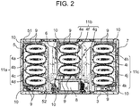
- FIG. 2 is a plan view illustrating a state where a top plate has been removed, according to the first exemplary embodiment of the present invention.
- FIG. 3 is an exploded perspective view of heating coil units in the induction heating cooker according to the first exemplary embodiment of the present invention.
- FIG. 4 is a cross-sectional view of main portions of the induction heating cooker, illustrating flows of magnetic lines of forces in the induction heating cooker illustrated in FIG. 1 .
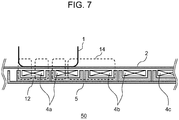
- FIG. 7 illustrates a cross-sectional view of main portions of a conventional induction heating cooker, illustrating flows of magnetic lines of forces in conventional heating coil units, which corresponds to the induction heating cooker illustrated in FIG. 4 from which second ferrites and third ferrites are removed.
- induction heating cooker 100 having a multi-coil structure, which is constituted by a plurality of heating coils 4 and the like.
- first ferrites 12 near lower bottom surfaces of respective heating coil units 4, near outer peripheries thereof, and near inner peripheries thereof, there are provided first ferrites 12.
- heating coil units 4 are placed in such a way as to be arranged in planar longitudinal and lateral rows, inside outer shell 3.
- heating coil units 4 have an elliptical shape with a length of about 80 mm in a transverse direction and with a length of about 180 mm in a longitudinal direction.
- each four or three heating coil units 4, out of heating coil units 4 are secured through an adhesive agent made of silicon and the like, in such a way as to be arranged, closely to each other, on shield boxes 5, 6, 7.
- top plate 2 there is an area capable of heating, just above an area in which heating coil units 4 are placed. Even if two or more to-be-heated objects are placed within this area capable of heating, it is possible to perform induction heating thereon.
- manipulation display portion 8 in an area outside the area capable of heating, in which heating coil units 4 are placed.
- Manipulation display portion 8 is constituted by a liquid crystal display portion, and a touch panel overlaid thereon.
- Manipulation display portion 8 is configured to display manipulation buttons and to display the contents of manipulations and the contents of operations, through light emission, in manipulation display portion 8, when induction heating cooker 100 has been activated.
- shield boxes 5, 6, 7 have bottom surfaces having asymmetric polygonal shapes (for example, hexagonal shapes) provided by cutting partial corners from substantially-rectangular shapes, substantially-polygonal shapes having rounded corner portions (with R shapes), and other shapes, in order to be prevented from interfering with other components in induction heating cooker 100. Further, shield boxes 5, 6, 7 are formed to have substantially-box-type shapes (shield boxes) having bottom surfaces, and side walls provided on the bottom surfaces at their outer peripheries. Further, in shield box 5, heating coil units 4a, 4b, 4c, 4d are placed to form coil module 11a. In shield box 6, heating coil units 4e, 4f, 4g are placed to form coil module 11b.
- asymmetric polygonal shapes for example, hexagonal shapes
- shield boxes 5, 6, 7 are formed to have substantially-box-type shapes (shield boxes) having bottom
- coil module 11c In shield box 7, heating coil units 4h, 4i, 4j, 4k are placed to form coil module 11c. Coil module 11a and coil module 11c are placed in a leftwardly/rightwardly inverted manner (bisymmetrically). Further, in respective coil modules 11a, 11b, 11c, respective second ferrites 9 are placed in shield boxes 5, 6, 7 through an adhesive agent made of silicon and the like, at the ends in the longitudinal direction, and, furthermore, third ferrites 10 are selectively placed therein.
- FIGS. 4 and 7 broken lines indicate magnetic lines of forces 13, 14.
- respective heating coil units 4a, 4b, 4c, 4d are placed closely to each other and, therefore, magnetic fluxes generated from respective heating coil units 4a, 4b, 4c, 4d are influenced by first ferrites 12 adjacent thereto. Namely, magnetic fluxes generated from heating coil unit 4a are influenced by first ferrites 12 placed under heating coil unit 4b. Further, magnetic fluxes generated from heating coil unit 4b are influenced by first ferrites 12 placed under heating coil units 4a and 4c.
- heating coil units 4a, 4c adjacent to heating coil unit 4b are placed evenly in a forward and rearward (longitudinal) direction, and the walls of shield box 5 are placed substantially evenly in a leftward and rightward (lateral) direction, so that magnetic fluxes generated from heating coil unit 4b are evenly spread in a substantially concentric shape.
- heating coil unit 4a when to-be-heated object 1 with a diameter of about 90 mm is heated by heating coil unit 4a placed at an end, only heating coil unit 4b is the heating coil unit adjacent to heating coil unit 4a. Further, in the leftward and rightward (lateral) direction, the corner portions of shield box 5 in one side are formed to have oblique walls and, therefore, are at shorter distances from heating coil unit 4a than those of the side walls of the other portions of shield box 5. Therefore, if there is no second ferrite 9, as indicated by the lines of magnetic forces 14 in FIG.
- a deflection will occur at a portion of magnetic fluxes generated from the heating coil unit, for example, in magnetic fluxes spread toward heating coil unit 4b in the inner side, which inhibits magnetic fluxes from being concentrated in to-be-heated object 1. Further, if there is no third ferrite 10, the same phenomenon will occur.
- second ferrites 9 are placed at such positions that these second ferrites 9 and heating coil unit 4b adjacent to heating coil unit 4a placed at the end are symmetric with respect to heating coil unit 4a placed at the end. Further, these second ferrites 9 are placed outside side walls of first ferrites 12 in heating coil unit 4a and, also, between these side walls and outer shell 3.
- third ferrites 10 can be also placed at positions facing the side walls of corner portions of shield box 5.
- third ferrite 10 is provided in such a way as to face the side wall of corner portion 51, wherein this third ferrite 10 has such a shape (an oblique shape, more specifically an oblique shape formed by partially cutting a corner of shield box 5 having a substantially-rectangular shape) that the shape of this third ferrite 10 and the oblique shape of the side wall of corner portion 52, which is diagonal to corner portion 51 of shield box 5, are substantially symmetric.
- heating coil units 4d, 4e, 4g, 4h, 4k placed at the ends as well as for the aforementioned heating coil unit 4a.
- to-be-heated object 1 with an outer diameter (diameter) of about 200 mm is heated with two or more heating coil units, for example, with heating coil units 4a and 4b
- to-be-heated object 1 with an outer diameter (diameter) of about 300 mm is heated with two or more heating coil units, for example, with heating coil units 4a, 4b, 4c, and in other cases, similarly, it is possible to provide the same effects.
- to-be-heated object 1 covering all of heating coil units 4a, 4b, 4c, 4d is heated, magnetic fluxes are balanced through to-be-heated object 1 and, therefore, the second ferrites do not exert significant effects.
- FIG. 5 is a plan view illustrating induction heating cooker 200 according to a second exemplary embodiment of the present invention, in a state where a top plate is removed therefrom.
- induction heating cooker 200 according to the present exemplary embodiment has the same basic structure as that of induction heating cooker 100 according to the first exemplary embodiment and, therefore, will be described mainly regarding differences therefrom. Further, the same elements as those of the first exemplary embodiment will be designated by the same reference characters and will not be described.
- Induction heating cooker 200 illustrated in FIG. 5 is different from induction heating cooker 100 according to the first exemplary embodiment, in that heating coil units 4 have a circular shape with an outer diameter (diameter) of about 65 mm and are placed in such a way as to be arranged in planar longitudinal and lateral rows.
- This structure has an advantage of having an increased area capable of induction heating and, also, has an advantage of being capable of heating to-be-heated objects with various sizes and shapes with excellent efficiency.
- second ferrites 9 are placed at such positions that second ferrites 9 and the inner heating coil units adjacent to the heating coil units placed at the ends, out of a plurality of heating coil units 4, are symmetric with respect to the heating coil units placed at the ends.
- heating coil units are arranged longitudinally and laterally (forwardly and rearwardly, and leftwardly and rightwardly).
- two heating coil units are arranged longitudinally and laterally, similarly, it is also possible to provide the same effects, by placing second ferrites 9 between the heating coil units and the outer shell 3.
- FIG. 6 is a plan view illustrating induction heating cooker 300 according to a third exemplary embodiment of the present invention, in a state where a top plate is removed therefrom.
- induction heating cooker 300 according to the present exemplary embodiment has the same basic structure as that of induction heating cooker 100 according to the first exemplary embodiment and, therefore, will be described mainly regarding differences therefrom. Further, the same elements as those of induction heating cooker 100 according to the first exemplary embodiment will be designated by the same reference characters and will not be described.
- Induction heating cooker 300 is different from induction heating cooker 100 according to the first exemplary embodiment, in terms of combinations of sizes and shapes of coils. More specifically, as illustrated in FIG. 6 , a plurality of heating coil units 4-1, 4-2, 4-3 having different sizes and shapes are placed in such a way as to be arranged closely to each other. Heating coil units 4-1 have a circular shape with an outer diameter (diameter) of about 80 mm, heating coil units 4-2 have an elliptical shape with a size of about 80 mm ⁇ about 180 mm, and heating coil units 4-3 have a circular shape with an outer diameter of about 180 mm. Heating coil units 4-2 are about twice the size of heating coil units 4-1. Further, similarly to in induction heating cooker 100 according to the first exemplary embodiment, first ferrites are placed under the respective heating coil units.
- the first ferrites have respective sizes (volumes) proportional to the sizes of the heating coil units provided with these first ferrites.
- the first ferrites under heating coil units 4-2 are about twice the size of the first ferrites under heating coil units 4-1.
- second ferrites 9-1, 9-2 in proportion to the sizes of the heating coil units adjacent to the heating coil units placed at the ends.
- second ferrites 9-1, 9-2 are placed at such positions that second ferrites 9-1, 9-2 and the heating coil units adjacent to the heating coil units placed at the ends are symmetric with respect to the heating coil units placed at the ends.
- second ferrites 9-1, 9-2 are placed between outer shell 3 and the heating coil units placed at the ends.
- second ferrites 9-2 are about twice the size (volume) of second ferrites 9-1.
- heating coil units 4-2 are about twice the size of heating coil units 4-1, and the first ferrites provided under heating coil units 4-2 are about twice the size of the first ferrites provided under heating coil units 4-1.
- heating coil unit 4-2 In cases where the heating coil unit adjacent to a heating coil unit (for example, heating coil unit 4-1 in FIG. 6 ) placed at an end is heating coil unit 4-2, there is formed second ferrite 9-2 which is proportional to the size of this heating coil unit 4-2, at such a position that this second ferrite 9-2 and this heating coil unit 4-2 are symmetric with respect to this heating coil unit 4-1 placed at the end. Further, this second ferrite 9-2 is placed between outer shell 3 and this heating coil unit 4-1 placed at the end.
- second ferrite 9-1 which is proportional to the size of this heating coil unit 4-1, at such a position that this second ferrite 9-1 and this heating coil unit 4-1 adjacent to this heating coil unit (for example, heating coil unit 4-3 in FIG. 6 ) placed at the end are symmetric with respect to this heating coil unit 4-3 placed at the end. Further, this second ferrite 9-1 is placed between outer shell 3 and this heating coil unit 4-3 placed at the end.
- an induction heating cooker in an example of an exemplary embodiment of the present invention includes an outer shell having an opening portion in its upper portion, a top plate configured to cover the opening portion and to place a to-be-heated object thereon, and a plurality of heating coil units for performing induction heating on the to-be-heated object, under the top plate, inside the outer shell.
- the heating coil units closely to each other.
- the heating coil units include a heating coil unit placed at an end, and a heating coil unit adjacent to the heating coil unit placed at the end.
- a second ferrite is provided adjacently to the heating coil unit placed at the end.
- the second ferrite is placed in an opposite side with respect to the heating coil unit placed at the end, from the heating coil unit adjacent to the heating coil unit placed at the end, and between the outer shell and this heating coil unit placed at the end.
- the induction heating cooker according to the present invention further includes a shield box configured to place the heating coil units therein. Further, in a corner portion of the shield box, a third ferrite is placed in such a way as to face a side wall of the corner portion, such that the third ferrite has such a shape that the shape of the third ferrite and the shape of a side wall of the shield box which is diagonal to the corner portion are substantially symmetric. With this structure, it is possible to suppress deflections of magnetic fluxes due to the shape of the shield box, which can suppress leakages of electromagnetic waves and radiant noises.
- the second ferrite is formed in proportion to the size of the heating coil unit adjacent to the heating coil unit placed at the end.
- the present invention even when a to-be-heated object such as a pan is heated with the heating coil unit placed at the end, it is possible to suppress deflections of magnetic fluxes, thereby causing magnetic fluxes to spread substantially in a concentric shape, so that magnetic fluxes are liable to concentrate in the to-be-heated object. This can suppress leakages of electromagnetic waves and radiant noises.
- an induction heating cooker capable of suppressing leakages of electromagnetic waves and radiant noises, no matter which heating coil unit is used, out of a plurality of heating coil units, for heating. Accordingly, the present invention can be widely utilized for induction heating cookers for household uses, business uses and other applications.
Landscapes
- Physics & Mathematics (AREA)
- Electromagnetism (AREA)
- Induction Heating Cooking Devices (AREA)
Description
- The present invention relates to induction heating cookers for use in ordinary homes and businesses.
- Conventionally, induction heating cookers have had heating coil units including ferrites, which are placed under top plates. Generally, induction heating cookers are configured to heat a single to-be-heated object, with a single heating coil unit. However, in recent years, there have been suggested induction heating cookers having multi-coil structures for heating a single to-be-heated object with a plurality of heating coil units (for example, PTL 1).
- However, in induction heating cookers having conventional multi-coil structures, heating coil units are placed closely to each other and, therefore, in the heating coil units adjacent to each other, magnetic fluxes generated therefrom are influenced by the ferrite cores in the heating coil units adjacent thereto. Further, in the heating coil units placed at the ends, magnetic fluxes are not spread in a substantially-concentric shape from the heating coil units, thereby inducing deflections therein. This inhibits magnetic fluxes from concentrating in a to-be-heated object such as a pan, thereby inducing the problem of increases of electromagnetic wave leakages and radiant noises.
-
JP2011090798 A -
- PTL 1: Unexamined Japanese Patent Publication No.
2014-044823 - PTL 2:
JP 2011 090798 A - The invention is defined by the independent claim, whereas the dependent claims and the embodiments described in the description relate to advantageous embodiments.
- The present invention was made in view of conventional problems as described above and aims at providing an induction heating cooker with excellent reliability which has a multi-coil structure including a plurality of heating coils and is capable of suppressing electromagnetic wave leakages and radiant noises.
- More specifically, in an example of an exemplary embodiment of the present invention, there is provided an induction heating cooker including an outer shell having an opening portion in an upper portion of the outer shell, a top plate configured to cover the opening portion and on which an object to be heated is placed, and a plurality of heating coil units provided under the top plate inside the outer shell and configured to heat the object to be heated. A first ferrite is provided under each of the plurality of heating coil units, and the heating coil units are placed closely to each other. Further, the heating coil units include a heating coil unit placed at an end, and a heating coil unit adjacent to the heating coil unit placed at the end. A second ferrite is provided adjacently to the heating coil unit placed at the end, among the plurality of heating coil units. The second ferrite is placed in an opposite side with respect to the heating coil unit placed at the end, from the heating coil unit adjacent thereto in an inner side, and between the outer shell and the heating coil unit placed at the end.
- With this structure, even when a to-be-heated object such as a pan is heated with the heating coil unit placed at the end, it is possible to suppress deflections of magnetic fluxes, thereby causing magnetic fluxes to spread substantially in a concentric shape, so that magnetic fluxes are liable to concentrate in the to-be-heated object. This can suppress leakages of electromagnetic waves and radiant noises.
-
-
FIG. 1 is an exploded perspective view of an induction heating cooker according to a first exemplary embodiment of the present invention. -
FIG. 2 is a plan view illustrating a state where a top plate has been removed, according to the first exemplary embodiment of the present invention. -
FIG. 3 is an exploded perspective view of heating coil units in the induction heating cooker according to the first exemplary embodiment of the present invention. -
FIG. 4 is a cross-sectional view of main portions of the induction heating cooker, illustrating flows of magnetic lines of forces in the induction heating cooker illustrated inFIG. 1 . -
FIG. 5 is a plan view illustrating a state where a top plate has been removed, according to a second exemplary embodiment of the present invention. -
FIG. 6 is a plan view illustrating a state where a top plate has been removed, according to a third exemplary embodiment of the present invention. -
FIG. 7 is a cross-sectional view of main portions of a conventional induction heating cooker, illustrating flows of magnetic lines of forces in conventional heating coil units, which corresponds to the induction heating cooker illustrated inFIG. 4 from which second ferrites and third ferrites are removed. - Hereinafter, the present invention will be described, with reference to the drawings. Further, the present invention is not intended to be restricted by the exemplary embodiments which will be described later.
-
FIG. 1 is an exploded perspective view of an induction heating cooker according to a first exemplary embodiment of the present invention.FIG. 2 is a plan view illustrating a state where a top plate has been removed, according to the first exemplary embodiment of the present invention.FIG. 3 is an exploded perspective view of heating coil units in the induction heating cooker according to the first exemplary embodiment of the present invention. Further,FIG. 4 is a cross-sectional view of main portions of the induction heating cooker, illustrating flows of magnetic lines of forces in the induction heating cooker illustrated inFIG. 1 .FIG. 7 illustrates a cross-sectional view of main portions of a conventional induction heating cooker, illustrating flows of magnetic lines of forces in conventional heating coil units, which corresponds to the induction heating cooker illustrated inFIG. 4 from which second ferrites and third ferrites are removed. - Referring to
FIG. 1 andFIG. 3 , undertop plate 2 covering an opening portion in an upper portion ofouter shell 3, there are provided various members ininduction heating cooker 100 having a multi-coil structure, which is constituted by a plurality ofheating coils 4 and the like. Near lower bottom surfaces of respectiveheating coil units 4, near outer peripheries thereof, and near inner peripheries thereof, there are providedfirst ferrites 12. - As illustrated in
FIG. 1 andFIG. 2 , a plurality ofheating coil units 4 are placed in such a way as to be arranged in planar longitudinal and lateral rows, insideouter shell 3. Ininduction heating cooker 100 according to the present exemplary embodiment,heating coil units 4 have an elliptical shape with a length of about 80 mm in a transverse direction and with a length of about 180 mm in a longitudinal direction. Further, for example, each four or threeheating coil units 4, out ofheating coil units 4, are secured through an adhesive agent made of silicon and the like, in such a way as to be arranged, closely to each other, onshield boxes top plate 2, there is an area capable of heating, just above an area in whichheating coil units 4 are placed. Even if two or more to-be-heated objects are placed within this area capable of heating, it is possible to perform induction heating thereon. - Further, in
top plate 2, there is placedmanipulation display portion 8, in an area outside the area capable of heating, in whichheating coil units 4 are placed.Manipulation display portion 8 is constituted by a liquid crystal display portion, and a touch panel overlaid thereon.Manipulation display portion 8 is configured to display manipulation buttons and to display the contents of manipulations and the contents of operations, through light emission, inmanipulation display portion 8, wheninduction heating cooker 100 has been activated. - Referring to
FIG. 2 ,shield boxes induction heating cooker 100. Further,shield boxes shield box 5,heating coil units coil module 11a. Inshield box 6,heating coil units coil module 11b. Inshield box 7,heating coil units coil module 11c.Coil module 11a andcoil module 11c are placed in a leftwardly/rightwardly inverted manner (bisymmetrically). Further, inrespective coil modules second ferrites 9 are placed inshield boxes third ferrites 10 are selectively placed therein. - In
FIGS. 4 and7 , broken lines indicate magnetic lines offorces - Hereinafter, there will be described
induction heating cooker 100 having the aforementioned structure according to the present exemplary embodiment, regarding operations and effects thereof. - At first, in
coil module 11a, respectiveheating coil units heating coil units first ferrites 12 adjacent thereto. Namely, magnetic fluxes generated fromheating coil unit 4a are influenced byfirst ferrites 12 placed underheating coil unit 4b. Further, magnetic fluxes generated fromheating coil unit 4b are influenced byfirst ferrites 12 placed underheating coil units - For example, when to-be-heated
object 1 with a diameter of about 90 mm is heated byheating coil unit 4b,heating coil units heating coil unit 4b are placed evenly in a forward and rearward (longitudinal) direction, and the walls ofshield box 5 are placed substantially evenly in a leftward and rightward (lateral) direction, so that magnetic fluxes generated fromheating coil unit 4b are evenly spread in a substantially concentric shape. - However, when to-be-heated
object 1 with a diameter of about 90 mm is heated byheating coil unit 4a placed at an end, onlyheating coil unit 4b is the heating coil unit adjacent toheating coil unit 4a. Further, in the leftward and rightward (lateral) direction, the corner portions ofshield box 5 in one side are formed to have oblique walls and, therefore, are at shorter distances fromheating coil unit 4a than those of the side walls of the other portions ofshield box 5. Therefore, if there is nosecond ferrite 9, as indicated by the lines ofmagnetic forces 14 inFIG. 7 , a deflection will occur at a portion of magnetic fluxes generated from the heating coil unit, for example, in magnetic fluxes spread towardheating coil unit 4b in the inner side, which inhibits magnetic fluxes from being concentrated in to-be-heated object 1. Further, if there is nothird ferrite 10, the same phenomenon will occur. - On the other hand, in
induction heating cooker 100 according to the present exemplary embodiment, as illustrated inFIG. 4 ,second ferrites 9 are placed at such positions that thesesecond ferrites 9 andheating coil unit 4b adjacent toheating coil unit 4a placed at the end are symmetric with respect toheating coil unit 4a placed at the end. Further, thesesecond ferrites 9 are placed outside side walls offirst ferrites 12 inheating coil unit 4a and, also, between these side walls andouter shell 3. - Further, as illustrated in
FIG. 2 andFIG. 3 ,third ferrites 10 can be also placed at positions facing the side walls of corner portions ofshield box 5. For example, ininduction heating cooker 100 according to the present exemplary embodiment, as illustrated inFIG. 2 ,third ferrite 10 is provided in such a way as to face the side wall ofcorner portion 51, wherein thisthird ferrite 10 has such a shape (an oblique shape, more specifically an oblique shape formed by partially cutting a corner ofshield box 5 having a substantially-rectangular shape) that the shape of thisthird ferrite 10 and the oblique shape of the side wall ofcorner portion 52, which is diagonal to cornerportion 51 ofshield box 5, are substantially symmetric. - With this structure, it is possible to suppress deflections of magnetic fluxes as illustrated in the lines of
magnetic forces 13 inFIG. 4 , which causes magnetic fluxes to spread in a substantially-concentric shape. Therefore, magnetic fluxes are liable to concentrate in to-be-heated object 1, which can suppress leakages of electromagnetic waves and radiant noises, which enables provision ofinduction heating cooker 100 having excellent reliability. - According to the present exemplary embodiment, it is also possible to provide the same effects for
heating coil units heating coil unit 4a. Further, in cases where to-be-heated object 1 with an outer diameter (diameter) of about 200 mm is heated with two or more heating coil units, for example, withheating coil units be-heated object 1 with an outer diameter (diameter) of about 300 mm is heated with two or more heating coil units, for example, withheating coil units be-heated object 1 covering all ofheating coil units be-heated object 1 and, therefore, the second ferrites do not exert significant effects. -
FIG. 5 is a plan view illustratinginduction heating cooker 200 according to a second exemplary embodiment of the present invention, in a state where a top plate is removed therefrom. Further,induction heating cooker 200 according to the present exemplary embodiment has the same basic structure as that ofinduction heating cooker 100 according to the first exemplary embodiment and, therefore, will be described mainly regarding differences therefrom. Further, the same elements as those of the first exemplary embodiment will be designated by the same reference characters and will not be described. -
Induction heating cooker 200 illustrated inFIG. 5 is different frominduction heating cooker 100 according to the first exemplary embodiment, in thatheating coil units 4 have a circular shape with an outer diameter (diameter) of about 65 mm and are placed in such a way as to be arranged in planar longitudinal and lateral rows. This structure has an advantage of having an increased area capable of induction heating and, also, has an advantage of being capable of heating to-be-heated objects with various sizes and shapes with excellent efficiency. Ininduction heating cooker 200 according to the present exemplary embodiment, similarly,second ferrites 9 are placed at such positions thatsecond ferrites 9 and the inner heating coil units adjacent to the heating coil units placed at the ends, out of a plurality ofheating coil units 4, are symmetric with respect to the heating coil units placed at the ends. With this structure, when a to-be-heated object is heated with a heating coil unit at an end, it is possible to suppress deflection of magnetic fluxes due to the first ferrites provided in the inner heating coil unit adjacent to the heating coil unit under the to-be-heated object. Therefore, magnetic fluxes are liable to concentrate in the to-be-heated object, which can suppress leakages of electromagnetic waves and radiant noises. This enables provision of induction heating cooker having excellent reliability. - Further, in the present exemplary embodiment, there has been described a case where three or more heating coil units are arranged longitudinally and laterally (forwardly and rearwardly, and leftwardly and rightwardly). However, when two heating coil units are arranged longitudinally and laterally, similarly, it is also possible to provide the same effects, by placing
second ferrites 9 between the heating coil units and theouter shell 3. -
FIG. 6 is a plan view illustratinginduction heating cooker 300 according to a third exemplary embodiment of the present invention, in a state where a top plate is removed therefrom. Further,induction heating cooker 300 according to the present exemplary embodiment has the same basic structure as that ofinduction heating cooker 100 according to the first exemplary embodiment and, therefore, will be described mainly regarding differences therefrom. Further, the same elements as those ofinduction heating cooker 100 according to the first exemplary embodiment will be designated by the same reference characters and will not be described. -
Induction heating cooker 300 according to the present embodiment is different frominduction heating cooker 100 according to the first exemplary embodiment, in terms of combinations of sizes and shapes of coils. More specifically, as illustrated inFIG. 6 , a plurality of heating coil units 4-1, 4-2, 4-3 having different sizes and shapes are placed in such a way as to be arranged closely to each other. Heating coil units 4-1 have a circular shape with an outer diameter (diameter) of about 80 mm, heating coil units 4-2 have an elliptical shape with a size of about 80 mm × about 180 mm, and heating coil units 4-3 have a circular shape with an outer diameter of about 180 mm. Heating coil units 4-2 are about twice the size of heating coil units 4-1. Further, similarly to ininduction heating cooker 100 according to the first exemplary embodiment, first ferrites are placed under the respective heating coil units. - Generally, the first ferrites have respective sizes (volumes) proportional to the sizes of the heating coil units provided with these first ferrites. In
induction heating cooker 300 according to the present exemplary embodiment, similarly, the first ferrites under heating coil units 4-2 are about twice the size of the first ferrites under heating coil units 4-1. - In
induction heating cooker 300 according to the present exemplary embodiment, there are further formed second ferrites 9-1, 9-2, in proportion to the sizes of the heating coil units adjacent to the heating coil units placed at the ends. As illustrated inFIG. 6 , second ferrites 9-1, 9-2 are placed at such positions that second ferrites 9-1, 9-2 and the heating coil units adjacent to the heating coil units placed at the ends are symmetric with respect to the heating coil units placed at the ends. Further, second ferrites 9-1, 9-2 are placed betweenouter shell 3 and the heating coil units placed at the ends. - As illustrated in
FIG. 6 , second ferrites 9-2 are about twice the size (volume) of second ferrites 9-1. On the other hand, heating coil units 4-2 are about twice the size of heating coil units 4-1, and the first ferrites provided under heating coil units 4-2 are about twice the size of the first ferrites provided under heating coil units 4-1. - In cases where the heating coil unit adjacent to a heating coil unit (for example, heating coil unit 4-1 in
FIG. 6 ) placed at an end is heating coil unit 4-2, there is formed second ferrite 9-2 which is proportional to the size of this heating coil unit 4-2, at such a position that this second ferrite 9-2 and this heating coil unit 4-2 are symmetric with respect to this heating coil unit 4-1 placed at the end. Further, this second ferrite 9-2 is placed betweenouter shell 3 and this heating coil unit 4-1 placed at the end. - Further, in cases where the heating coil unit adjacent to a heating coil unit placed at an end is heating coil unit 4-1, there is placed second ferrite 9-1 which is proportional to the size of this heating coil unit 4-1, at such a position that this second ferrite 9-1 and this heating coil unit 4-1 adjacent to this heating coil unit (for example, heating coil unit 4-3 in
FIG. 6 ) placed at the end are symmetric with respect to this heating coil unit 4-3 placed at the end. Further, this second ferrite 9-1 is placed betweenouter shell 3 and this heating coil unit 4-3 placed at the end. - With this structure, it is possible to suppress deflections of magnetic fluxes due to the first ferrites, which are proportional to the sizes of the heating coil units adjacent to the heating coil units placed at the ends, in inner sides of
induction heating cooker 300. This can suppress leakages of electromagnetic waves and radiant noises. This enables provision of an induction heating cooker having excellent reliability. - As described above, an induction heating cooker in an example of an exemplary embodiment of the present invention includes an outer shell having an opening portion in its upper portion, a top plate configured to cover the opening portion and to place a to-be-heated object thereon, and a plurality of heating coil units for performing induction heating on the to-be-heated object, under the top plate, inside the outer shell. There are provided respective first ferrites under the heating coil units. Further, under the top plate, there are placed the heating coil units closely to each other. The heating coil units include a heating coil unit placed at an end, and a heating coil unit adjacent to the heating coil unit placed at the end. A second ferrite is provided adjacently to the heating coil unit placed at the end. Further, the second ferrite is placed in an opposite side with respect to the heating coil unit placed at the end, from the heating coil unit adjacent to the heating coil unit placed at the end, and between the outer shell and this heating coil unit placed at the end. With this structure, even when a to-be-heated object such as a pan is heated with the heating coil unit placed at the end, it is possible to suppress deflections of magnetic fluxes, thereby causing magnetic fluxes to spread substantially in a concentric shape, so that magnetic fluxes are liable to concentrate in the to-be-heated object. This can suppress leakages of electromagnetic waves and radiant noises.
- The induction heating cooker according to the present invention further includes a shield box configured to place the heating coil units therein. Further, in a corner portion of the shield box, a third ferrite is placed in such a way as to face a side wall of the corner portion, such that the third ferrite has such a shape that the shape of the third ferrite and the shape of a side wall of the shield box which is diagonal to the corner portion are substantially symmetric. With this structure, it is possible to suppress deflections of magnetic fluxes due to the shape of the shield box, which can suppress leakages of electromagnetic waves and radiant noises.
- In the induction heating cooker in an example of an exemplary embodiment of the present invention, the second ferrite is formed in proportion to the size of the heating coil unit adjacent to the heating coil unit placed at the end. With this structure, it is possible to certainly suppress deflections of magnetic fluxes due to the sizes of the heating coil units, which can suppress leakages of electromagnetic waves and radiant noises.
- As described above, according to the present invention, even when a to-be-heated object such as a pan is heated with the heating coil unit placed at the end, it is possible to suppress deflections of magnetic fluxes, thereby causing magnetic fluxes to spread substantially in a concentric shape, so that magnetic fluxes are liable to concentrate in the to-be-heated object. This can suppress leakages of electromagnetic waves and radiant noises.
- As described above, according to the present invention, there is provided an induction heating cooker capable of suppressing leakages of electromagnetic waves and radiant noises, no matter which heating coil unit is used, out of a plurality of heating coil units, for heating. Accordingly, the present invention can be widely utilized for induction heating cookers for household uses, business uses and other applications.
-
- 1: to-be-heated object
- 2: top plate
- 3: outer shell
- 4, 4a, 4b, 4c, 4d, 4e, 4f, 4g, 4h, 4i, 4j, 4k, 4-1, 4-2, 4-3: heating coil unit
- 5, 6, 7: shield box
- 8: manipulation display portion
- 9, 9-1, 9-2: second ferrite
- 10: third ferrite
- 11a, 11b, 11c: coil module
- 12: first ferrite
- 13, 14: magnetic lines of forces
- 51, 52: corner portion
Claims (2)
- An induction heating cooker comprising:an outer shell (3) having an opening portion in an upper portion of the outer shell (3);a top plate (2) configured to cover the opening portion and on which an object to be heated (1) is placed; anda plurality of heating coil units (4) provided under the top plate (2) inside the outer shell (3) and configured to heat the object to be heated (1);whereina first ferrite (12) is provided under each of the plurality of heating coil units (4),the heating coil units (4) are placed closely to each other and include a heating coil unit placed at an end, and a heating coil unit adjacent to the heating coil unit placed at the end,a second ferrite (9) is provided adjacently to the heating coil unit placed at the end, andthe second ferrite (9) is placed in an opposite side with respect to the heating coil unit placed at the end, from the heating coil unit adjacent to the heating coil unit placed at the end, and between the outer shell (3) and the heating coil unit placed at the end,characterized by a shield box (5) in which the plurality of heating coil units (4) are placed, whereinin a corner portion of the shield box, a third ferrite (10) is placed in such a way as to face a side wall of the corner portion, wherein the third ferrite (10) has a shape which is substantially symmetrical with respect to a shape of a side wall of the shield box (5) located at a position diagonal to the corner portion.
- The induction heating cooker according to claim 1, wherein
the second ferrite (9) is formed in proportion to a size of the heating coil unit adjacent to the heating coil unit placed at the end.
Applications Claiming Priority (2)
| Application Number | Priority Date | Filing Date | Title |
|---|---|---|---|
| JP2015089957 | 2015-04-27 | ||
| PCT/JP2016/002139 WO2016174856A1 (en) | 2015-04-27 | 2016-04-21 | Induction heating cooking device |
Publications (3)
| Publication Number | Publication Date |
|---|---|
| EP3291644A1 EP3291644A1 (en) | 2018-03-07 |
| EP3291644A4 EP3291644A4 (en) | 2018-04-25 |
| EP3291644B1 true EP3291644B1 (en) | 2021-06-09 |
Family
ID=57198374
Family Applications (1)
| Application Number | Title | Priority Date | Filing Date |
|---|---|---|---|
| EP16786135.0A Active EP3291644B1 (en) | 2015-04-27 | 2016-04-21 | Induction heating cooking device |
Country Status (3)
| Country | Link |
|---|---|
| EP (1) | EP3291644B1 (en) |
| JP (1) | JP6708208B2 (en) |
| WO (1) | WO2016174856A1 (en) |
Families Citing this family (4)
| Publication number | Priority date | Publication date | Assignee | Title |
|---|---|---|---|---|
| CN115779207A (en) | 2016-03-24 | 2023-03-14 | 特鲁德尔医学国际公司 | Respiratory care system with electronic indicator |
| KR20250043269A (en) * | 2023-09-21 | 2025-03-28 | 엘지전자 주식회사 | Cooking appliance |
| WO2025063781A1 (en) * | 2023-09-21 | 2025-03-27 | 엘지전자 주식회사 | Electric range |
| WO2025063775A1 (en) * | 2023-09-21 | 2025-03-27 | 엘지전자 주식회사 | Electric range |
Family Cites Families (6)
| Publication number | Priority date | Publication date | Assignee | Title |
|---|---|---|---|---|
| JP4909968B2 (en) * | 2008-09-29 | 2012-04-04 | 日立アプライアンス株式会社 | Electromagnetic induction heating device |
| JP5235836B2 (en) * | 2009-10-20 | 2013-07-10 | 三菱電機株式会社 | Induction cooking device |
| JP5836743B2 (en) * | 2011-10-03 | 2015-12-24 | 三菱電機株式会社 | Induction heating cooker |
| JP2013137938A (en) * | 2011-12-28 | 2013-07-11 | Panasonic Corp | Induction heating cooker |
| JP5854874B2 (en) * | 2012-02-21 | 2016-02-09 | 三菱電機株式会社 | Induction heating cooker |
| JP5637265B2 (en) * | 2013-07-11 | 2014-12-10 | パナソニック株式会社 | Induction heating cooker |
-
2016
- 2016-04-21 EP EP16786135.0A patent/EP3291644B1/en active Active
- 2016-04-21 JP JP2017515385A patent/JP6708208B2/en active Active
- 2016-04-21 WO PCT/JP2016/002139 patent/WO2016174856A1/en not_active Ceased
Non-Patent Citations (1)
| Title |
|---|
| None * |
Also Published As
| Publication number | Publication date |
|---|---|
| JP6708208B2 (en) | 2020-06-10 |
| EP3291644A1 (en) | 2018-03-07 |
| WO2016174856A1 (en) | 2016-11-03 |
| EP3291644A4 (en) | 2018-04-25 |
| JPWO2016174856A1 (en) | 2018-02-15 |
Similar Documents
| Publication | Publication Date | Title |
|---|---|---|
| CN106471864B (en) | Induction heating apparatus and induced cooking utensils | |
| EP3291644A1 (en) | Induction heating cooking device | |
| ES2442180T3 (en) | Induction cooking surface | |
| EP3041314B1 (en) | Induction heating cooker | |
| EP2207401A2 (en) | Cooking apparatus and heating device including working coils thereof | |
| EP2094060A2 (en) | Electric range and induction coil unit used therein | |
| KR20100121644A (en) | Power reception coil unit | |
| CN110036691A (en) | Heating module for electromagnetic oven and the electromagnetic oven including it | |
| JPWO2018229967A1 (en) | Induction heating cooker and sensor unit | |
| JP2022092054A (en) | Heating coil unit and induction heating cooker equipped with it | |
| JP6528119B2 (en) | Cooker | |
| JP2016129164A (en) | Power receiving device and power transmitting device | |
| JP2020064722A (en) | Induction heating coil unit and induction heating cooker | |
| KR102187884B1 (en) | Working coil base | |
| CN110557855A (en) | Heating coil unit and induction heating cooker having the same | |
| JP5985919B2 (en) | Induction heating device | |
| WO2017093168A1 (en) | An inductive coil unit | |
| JP7138457B2 (en) | induction cooker | |
| KR102165570B1 (en) | Working coil assembly comprising dual coil | |
| EP3297399B1 (en) | Induction heating cooking device | |
| JP5836743B2 (en) | Induction heating cooker | |
| KR102120175B1 (en) | Working coil assembly | |
| JP2016096160A5 (en) | ||
| CN205546016U (en) | Electromagnetic heating device for cooking utensils and cooking utensils | |
| JP2005026204A (en) | Induction heating cooker |
Legal Events
| Date | Code | Title | Description |
|---|---|---|---|
| STAA | Information on the status of an ep patent application or granted ep patent |
Free format text: STATUS: THE INTERNATIONAL PUBLICATION HAS BEEN MADE |
|
| PUAI | Public reference made under article 153(3) epc to a published international application that has entered the european phase |
Free format text: ORIGINAL CODE: 0009012 |
|
| STAA | Information on the status of an ep patent application or granted ep patent |
Free format text: STATUS: REQUEST FOR EXAMINATION WAS MADE |
|
| 17P | Request for examination filed |
Effective date: 20170125 |
|
| AK | Designated contracting states |
Kind code of ref document: A1 Designated state(s): AL AT BE BG CH CY CZ DE DK EE ES FI FR GB GR HR HU IE IS IT LI LT LU LV MC MK MT NL NO PL PT RO RS SE SI SK SM TR |
|
| AX | Request for extension of the european patent |
Extension state: BA ME |
|
| A4 | Supplementary search report drawn up and despatched |
Effective date: 20180326 |
|
| RIC1 | Information provided on ipc code assigned before grant |
Ipc: H05B 6/12 20060101AFI20180320BHEP |
|
| DAV | Request for validation of the european patent (deleted) | ||
| DAX | Request for extension of the european patent (deleted) | ||
| STAA | Information on the status of an ep patent application or granted ep patent |
Free format text: STATUS: EXAMINATION IS IN PROGRESS |
|
| 17Q | First examination report despatched |
Effective date: 20200812 |
|
| GRAP | Despatch of communication of intention to grant a patent |
Free format text: ORIGINAL CODE: EPIDOSNIGR1 |
|
| STAA | Information on the status of an ep patent application or granted ep patent |
Free format text: STATUS: GRANT OF PATENT IS INTENDED |
|
| INTG | Intention to grant announced |
Effective date: 20201201 |
|
| GRAS | Grant fee paid |
Free format text: ORIGINAL CODE: EPIDOSNIGR3 |
|
| GRAA | (expected) grant |
Free format text: ORIGINAL CODE: 0009210 |
|
| STAA | Information on the status of an ep patent application or granted ep patent |
Free format text: STATUS: THE PATENT HAS BEEN GRANTED |
|
| AK | Designated contracting states |
Kind code of ref document: B1 Designated state(s): AL AT BE BG CH CY CZ DE DK EE ES FI FR GB GR HR HU IE IS IT LI LT LU LV MC MK MT NL NO PL PT RO RS SE SI SK SM TR |
|
| REG | Reference to a national code |
Ref country code: GB Ref legal event code: FG4D |
|
| REG | Reference to a national code |
Ref country code: CH Ref legal event code: EP Ref country code: AT Ref legal event code: REF Ref document number: 1401513 Country of ref document: AT Kind code of ref document: T Effective date: 20210615 |
|
| REG | Reference to a national code |
Ref country code: DE Ref legal event code: R096 Ref document number: 602016059164 Country of ref document: DE |
|
| REG | Reference to a national code |
Ref country code: IE Ref legal event code: FG4D |
|
| REG | Reference to a national code |
Ref country code: LT Ref legal event code: MG9D |
|
| PG25 | Lapsed in a contracting state [announced via postgrant information from national office to epo] |
Ref country code: LT Free format text: LAPSE BECAUSE OF FAILURE TO SUBMIT A TRANSLATION OF THE DESCRIPTION OR TO PAY THE FEE WITHIN THE PRESCRIBED TIME-LIMIT Effective date: 20210609 Ref country code: FI Free format text: LAPSE BECAUSE OF FAILURE TO SUBMIT A TRANSLATION OF THE DESCRIPTION OR TO PAY THE FEE WITHIN THE PRESCRIBED TIME-LIMIT Effective date: 20210609 Ref country code: HR Free format text: LAPSE BECAUSE OF FAILURE TO SUBMIT A TRANSLATION OF THE DESCRIPTION OR TO PAY THE FEE WITHIN THE PRESCRIBED TIME-LIMIT Effective date: 20210609 Ref country code: BG Free format text: LAPSE BECAUSE OF FAILURE TO SUBMIT A TRANSLATION OF THE DESCRIPTION OR TO PAY THE FEE WITHIN THE PRESCRIBED TIME-LIMIT Effective date: 20210909 |
|
| REG | Reference to a national code |
Ref country code: AT Ref legal event code: MK05 Ref document number: 1401513 Country of ref document: AT Kind code of ref document: T Effective date: 20210609 |
|
| REG | Reference to a national code |
Ref country code: NL Ref legal event code: MP Effective date: 20210609 |
|
| PG25 | Lapsed in a contracting state [announced via postgrant information from national office to epo] |
Ref country code: LV Free format text: LAPSE BECAUSE OF FAILURE TO SUBMIT A TRANSLATION OF THE DESCRIPTION OR TO PAY THE FEE WITHIN THE PRESCRIBED TIME-LIMIT Effective date: 20210609 Ref country code: GR Free format text: LAPSE BECAUSE OF FAILURE TO SUBMIT A TRANSLATION OF THE DESCRIPTION OR TO PAY THE FEE WITHIN THE PRESCRIBED TIME-LIMIT Effective date: 20210910 Ref country code: RS Free format text: LAPSE BECAUSE OF FAILURE TO SUBMIT A TRANSLATION OF THE DESCRIPTION OR TO PAY THE FEE WITHIN THE PRESCRIBED TIME-LIMIT Effective date: 20210609 Ref country code: SE Free format text: LAPSE BECAUSE OF FAILURE TO SUBMIT A TRANSLATION OF THE DESCRIPTION OR TO PAY THE FEE WITHIN THE PRESCRIBED TIME-LIMIT Effective date: 20210609 Ref country code: NO Free format text: LAPSE BECAUSE OF FAILURE TO SUBMIT A TRANSLATION OF THE DESCRIPTION OR TO PAY THE FEE WITHIN THE PRESCRIBED TIME-LIMIT Effective date: 20210909 |
|
| PG25 | Lapsed in a contracting state [announced via postgrant information from national office to epo] |
Ref country code: EE Free format text: LAPSE BECAUSE OF FAILURE TO SUBMIT A TRANSLATION OF THE DESCRIPTION OR TO PAY THE FEE WITHIN THE PRESCRIBED TIME-LIMIT Effective date: 20210609 Ref country code: CZ Free format text: LAPSE BECAUSE OF FAILURE TO SUBMIT A TRANSLATION OF THE DESCRIPTION OR TO PAY THE FEE WITHIN THE PRESCRIBED TIME-LIMIT Effective date: 20210609 Ref country code: SK Free format text: LAPSE BECAUSE OF FAILURE TO SUBMIT A TRANSLATION OF THE DESCRIPTION OR TO PAY THE FEE WITHIN THE PRESCRIBED TIME-LIMIT Effective date: 20210609 Ref country code: SM Free format text: LAPSE BECAUSE OF FAILURE TO SUBMIT A TRANSLATION OF THE DESCRIPTION OR TO PAY THE FEE WITHIN THE PRESCRIBED TIME-LIMIT Effective date: 20210609 Ref country code: AT Free format text: LAPSE BECAUSE OF FAILURE TO SUBMIT A TRANSLATION OF THE DESCRIPTION OR TO PAY THE FEE WITHIN THE PRESCRIBED TIME-LIMIT Effective date: 20210609 Ref country code: PT Free format text: LAPSE BECAUSE OF FAILURE TO SUBMIT A TRANSLATION OF THE DESCRIPTION OR TO PAY THE FEE WITHIN THE PRESCRIBED TIME-LIMIT Effective date: 20211011 Ref country code: RO Free format text: LAPSE BECAUSE OF FAILURE TO SUBMIT A TRANSLATION OF THE DESCRIPTION OR TO PAY THE FEE WITHIN THE PRESCRIBED TIME-LIMIT Effective date: 20210609 Ref country code: NL Free format text: LAPSE BECAUSE OF FAILURE TO SUBMIT A TRANSLATION OF THE DESCRIPTION OR TO PAY THE FEE WITHIN THE PRESCRIBED TIME-LIMIT Effective date: 20210609 Ref country code: ES Free format text: LAPSE BECAUSE OF FAILURE TO SUBMIT A TRANSLATION OF THE DESCRIPTION OR TO PAY THE FEE WITHIN THE PRESCRIBED TIME-LIMIT Effective date: 20210609 |
|
| PG25 | Lapsed in a contracting state [announced via postgrant information from national office to epo] |
Ref country code: PL Free format text: LAPSE BECAUSE OF FAILURE TO SUBMIT A TRANSLATION OF THE DESCRIPTION OR TO PAY THE FEE WITHIN THE PRESCRIBED TIME-LIMIT Effective date: 20210609 |
|
| REG | Reference to a national code |
Ref country code: DE Ref legal event code: R097 Ref document number: 602016059164 Country of ref document: DE |
|
| PLBE | No opposition filed within time limit |
Free format text: ORIGINAL CODE: 0009261 |
|
| STAA | Information on the status of an ep patent application or granted ep patent |
Free format text: STATUS: NO OPPOSITION FILED WITHIN TIME LIMIT |
|
| PG25 | Lapsed in a contracting state [announced via postgrant information from national office to epo] |
Ref country code: DK Free format text: LAPSE BECAUSE OF FAILURE TO SUBMIT A TRANSLATION OF THE DESCRIPTION OR TO PAY THE FEE WITHIN THE PRESCRIBED TIME-LIMIT Effective date: 20210609 |
|
| 26N | No opposition filed |
Effective date: 20220310 |
|
| PG25 | Lapsed in a contracting state [announced via postgrant information from national office to epo] |
Ref country code: AL Free format text: LAPSE BECAUSE OF FAILURE TO SUBMIT A TRANSLATION OF THE DESCRIPTION OR TO PAY THE FEE WITHIN THE PRESCRIBED TIME-LIMIT Effective date: 20210609 |
|
| PG25 | Lapsed in a contracting state [announced via postgrant information from national office to epo] |
Ref country code: IT Free format text: LAPSE BECAUSE OF FAILURE TO SUBMIT A TRANSLATION OF THE DESCRIPTION OR TO PAY THE FEE WITHIN THE PRESCRIBED TIME-LIMIT Effective date: 20210609 |
|
| REG | Reference to a national code |
Ref country code: CH Ref legal event code: PL |
|
| GBPC | Gb: european patent ceased through non-payment of renewal fee |
Effective date: 20220421 |
|
| REG | Reference to a national code |
Ref country code: BE Ref legal event code: MM Effective date: 20220430 |
|
| PG25 | Lapsed in a contracting state [announced via postgrant information from national office to epo] |
Ref country code: MC Free format text: LAPSE BECAUSE OF FAILURE TO SUBMIT A TRANSLATION OF THE DESCRIPTION OR TO PAY THE FEE WITHIN THE PRESCRIBED TIME-LIMIT Effective date: 20210609 Ref country code: LU Free format text: LAPSE BECAUSE OF NON-PAYMENT OF DUE FEES Effective date: 20220421 Ref country code: LI Free format text: LAPSE BECAUSE OF NON-PAYMENT OF DUE FEES Effective date: 20220430 Ref country code: GB Free format text: LAPSE BECAUSE OF NON-PAYMENT OF DUE FEES Effective date: 20220421 Ref country code: FR Free format text: LAPSE BECAUSE OF NON-PAYMENT OF DUE FEES Effective date: 20220430 Ref country code: CH Free format text: LAPSE BECAUSE OF NON-PAYMENT OF DUE FEES Effective date: 20220430 |
|
| PG25 | Lapsed in a contracting state [announced via postgrant information from national office to epo] |
Ref country code: BE Free format text: LAPSE BECAUSE OF NON-PAYMENT OF DUE FEES Effective date: 20220430 |
|
| PG25 | Lapsed in a contracting state [announced via postgrant information from national office to epo] |
Ref country code: IE Free format text: LAPSE BECAUSE OF NON-PAYMENT OF DUE FEES Effective date: 20220421 |
|
| PG25 | Lapsed in a contracting state [announced via postgrant information from national office to epo] |
Ref country code: HU Free format text: LAPSE BECAUSE OF FAILURE TO SUBMIT A TRANSLATION OF THE DESCRIPTION OR TO PAY THE FEE WITHIN THE PRESCRIBED TIME-LIMIT; INVALID AB INITIO Effective date: 20160421 |
|
| PG25 | Lapsed in a contracting state [announced via postgrant information from national office to epo] |
Ref country code: MK Free format text: LAPSE BECAUSE OF FAILURE TO SUBMIT A TRANSLATION OF THE DESCRIPTION OR TO PAY THE FEE WITHIN THE PRESCRIBED TIME-LIMIT Effective date: 20210609 Ref country code: CY Free format text: LAPSE BECAUSE OF FAILURE TO SUBMIT A TRANSLATION OF THE DESCRIPTION OR TO PAY THE FEE WITHIN THE PRESCRIBED TIME-LIMIT Effective date: 20210609 |
|
| PG25 | Lapsed in a contracting state [announced via postgrant information from national office to epo] |
Ref country code: MT Free format text: LAPSE BECAUSE OF FAILURE TO SUBMIT A TRANSLATION OF THE DESCRIPTION OR TO PAY THE FEE WITHIN THE PRESCRIBED TIME-LIMIT Effective date: 20210609 |
|
| PGFP | Annual fee paid to national office [announced via postgrant information from national office to epo] |
Ref country code: DE Payment date: 20250422 Year of fee payment: 10 |
|
| PG25 | Lapsed in a contracting state [announced via postgrant information from national office to epo] |
Ref country code: TR Free format text: LAPSE BECAUSE OF FAILURE TO SUBMIT A TRANSLATION OF THE DESCRIPTION OR TO PAY THE FEE WITHIN THE PRESCRIBED TIME-LIMIT Effective date: 20210609 |