EP3291136A1 - Automated vehicle lane change control system - Google Patents
Automated vehicle lane change control system Download PDFInfo
- Publication number
- EP3291136A1 EP3291136A1 EP17187266.6A EP17187266A EP3291136A1 EP 3291136 A1 EP3291136 A1 EP 3291136A1 EP 17187266 A EP17187266 A EP 17187266A EP 3291136 A1 EP3291136 A1 EP 3291136A1
- Authority
- EP
- European Patent Office
- Prior art keywords
- lane
- vehicle
- host
- change
- marking
- Prior art date
- Legal status (The legal status is an assumption and is not a legal conclusion. Google has not performed a legal analysis and makes no representation as to the accuracy of the status listed.)
- Ceased
Links
Images

Classifications
-
- B—PERFORMING OPERATIONS; TRANSPORTING
- B60—VEHICLES IN GENERAL
- B60W—CONJOINT CONTROL OF VEHICLE SUB-UNITS OF DIFFERENT TYPE OR DIFFERENT FUNCTION; CONTROL SYSTEMS SPECIALLY ADAPTED FOR HYBRID VEHICLES; ROAD VEHICLE DRIVE CONTROL SYSTEMS FOR PURPOSES NOT RELATED TO THE CONTROL OF A PARTICULAR SUB-UNIT
- B60W30/00—Purposes of road vehicle drive control systems not related to the control of a particular sub-unit, e.g. of systems using conjoint control of vehicle sub-units
- B60W30/08—Active safety systems predicting or avoiding probable or impending collision or attempting to minimise its consequences
- B60W30/095—Predicting travel path or likelihood of collision
-
- G—PHYSICS
- G05—CONTROLLING; REGULATING
- G05D—SYSTEMS FOR CONTROLLING OR REGULATING NON-ELECTRIC VARIABLES
- G05D1/00—Control of position, course, altitude or attitude of land, water, air or space vehicles, e.g. using automatic pilots
- G05D1/02—Control of position or course in two dimensions
- G05D1/021—Control of position or course in two dimensions specially adapted to land vehicles
- G05D1/0231—Control of position or course in two dimensions specially adapted to land vehicles using optical position detecting means
- G05D1/0246—Control of position or course in two dimensions specially adapted to land vehicles using optical position detecting means using a video camera in combination with image processing means
-
- B—PERFORMING OPERATIONS; TRANSPORTING
- B60—VEHICLES IN GENERAL
- B60W—CONJOINT CONTROL OF VEHICLE SUB-UNITS OF DIFFERENT TYPE OR DIFFERENT FUNCTION; CONTROL SYSTEMS SPECIALLY ADAPTED FOR HYBRID VEHICLES; ROAD VEHICLE DRIVE CONTROL SYSTEMS FOR PURPOSES NOT RELATED TO THE CONTROL OF A PARTICULAR SUB-UNIT
- B60W30/00—Purposes of road vehicle drive control systems not related to the control of a particular sub-unit, e.g. of systems using conjoint control of vehicle sub-units
- B60W30/08—Active safety systems predicting or avoiding probable or impending collision or attempting to minimise its consequences
-
- B—PERFORMING OPERATIONS; TRANSPORTING
- B60—VEHICLES IN GENERAL
- B60W—CONJOINT CONTROL OF VEHICLE SUB-UNITS OF DIFFERENT TYPE OR DIFFERENT FUNCTION; CONTROL SYSTEMS SPECIALLY ADAPTED FOR HYBRID VEHICLES; ROAD VEHICLE DRIVE CONTROL SYSTEMS FOR PURPOSES NOT RELATED TO THE CONTROL OF A PARTICULAR SUB-UNIT
- B60W30/00—Purposes of road vehicle drive control systems not related to the control of a particular sub-unit, e.g. of systems using conjoint control of vehicle sub-units
- B60W30/18—Propelling the vehicle
- B60W30/18009—Propelling the vehicle related to particular drive situations
- B60W30/18163—Lane change; Overtaking manoeuvres
-
- B—PERFORMING OPERATIONS; TRANSPORTING
- B60—VEHICLES IN GENERAL
- B60W—CONJOINT CONTROL OF VEHICLE SUB-UNITS OF DIFFERENT TYPE OR DIFFERENT FUNCTION; CONTROL SYSTEMS SPECIALLY ADAPTED FOR HYBRID VEHICLES; ROAD VEHICLE DRIVE CONTROL SYSTEMS FOR PURPOSES NOT RELATED TO THE CONTROL OF A PARTICULAR SUB-UNIT
- B60W40/00—Estimation or calculation of non-directly measurable driving parameters for road vehicle drive control systems not related to the control of a particular sub unit, e.g. by using mathematical models
- B60W40/02—Estimation or calculation of non-directly measurable driving parameters for road vehicle drive control systems not related to the control of a particular sub unit, e.g. by using mathematical models related to ambient conditions
-
- B—PERFORMING OPERATIONS; TRANSPORTING
- B60—VEHICLES IN GENERAL
- B60W—CONJOINT CONTROL OF VEHICLE SUB-UNITS OF DIFFERENT TYPE OR DIFFERENT FUNCTION; CONTROL SYSTEMS SPECIALLY ADAPTED FOR HYBRID VEHICLES; ROAD VEHICLE DRIVE CONTROL SYSTEMS FOR PURPOSES NOT RELATED TO THE CONTROL OF A PARTICULAR SUB-UNIT
- B60W60/00—Drive control systems specially adapted for autonomous road vehicles
- B60W60/001—Planning or execution of driving tasks
- B60W60/0015—Planning or execution of driving tasks specially adapted for safety
-
- B—PERFORMING OPERATIONS; TRANSPORTING
- B60—VEHICLES IN GENERAL
- B60W—CONJOINT CONTROL OF VEHICLE SUB-UNITS OF DIFFERENT TYPE OR DIFFERENT FUNCTION; CONTROL SYSTEMS SPECIALLY ADAPTED FOR HYBRID VEHICLES; ROAD VEHICLE DRIVE CONTROL SYSTEMS FOR PURPOSES NOT RELATED TO THE CONTROL OF A PARTICULAR SUB-UNIT
- B60W60/00—Drive control systems specially adapted for autonomous road vehicles
- B60W60/001—Planning or execution of driving tasks
- B60W60/0027—Planning or execution of driving tasks using trajectory prediction for other traffic participants
-
- G—PHYSICS
- G01—MEASURING; TESTING
- G01S—RADIO DIRECTION-FINDING; RADIO NAVIGATION; DETERMINING DISTANCE OR VELOCITY BY USE OF RADIO WAVES; LOCATING OR PRESENCE-DETECTING BY USE OF THE REFLECTION OR RERADIATION OF RADIO WAVES; ANALOGOUS ARRANGEMENTS USING OTHER WAVES
- G01S13/00—Systems using the reflection or reradiation of radio waves, e.g. radar systems; Analogous systems using reflection or reradiation of waves whose nature or wavelength is irrelevant or unspecified
- G01S13/86—Combinations of radar systems with non-radar systems, e.g. sonar, direction finder
- G01S13/867—Combination of radar systems with cameras
-
- G—PHYSICS
- G01—MEASURING; TESTING
- G01S—RADIO DIRECTION-FINDING; RADIO NAVIGATION; DETERMINING DISTANCE OR VELOCITY BY USE OF RADIO WAVES; LOCATING OR PRESENCE-DETECTING BY USE OF THE REFLECTION OR RERADIATION OF RADIO WAVES; ANALOGOUS ARRANGEMENTS USING OTHER WAVES
- G01S13/00—Systems using the reflection or reradiation of radio waves, e.g. radar systems; Analogous systems using reflection or reradiation of waves whose nature or wavelength is irrelevant or unspecified
- G01S13/88—Radar or analogous systems specially adapted for specific applications
- G01S13/93—Radar or analogous systems specially adapted for specific applications for anti-collision purposes
- G01S13/931—Radar or analogous systems specially adapted for specific applications for anti-collision purposes of land vehicles
-
- G—PHYSICS
- G01—MEASURING; TESTING
- G01S—RADIO DIRECTION-FINDING; RADIO NAVIGATION; DETERMINING DISTANCE OR VELOCITY BY USE OF RADIO WAVES; LOCATING OR PRESENCE-DETECTING BY USE OF THE REFLECTION OR RERADIATION OF RADIO WAVES; ANALOGOUS ARRANGEMENTS USING OTHER WAVES
- G01S15/00—Systems using the reflection or reradiation of acoustic waves, e.g. sonar systems
- G01S15/86—Combinations of sonar systems with lidar systems; Combinations of sonar systems with systems not using wave reflection
-
- G—PHYSICS
- G01—MEASURING; TESTING
- G01S—RADIO DIRECTION-FINDING; RADIO NAVIGATION; DETERMINING DISTANCE OR VELOCITY BY USE OF RADIO WAVES; LOCATING OR PRESENCE-DETECTING BY USE OF THE REFLECTION OR RERADIATION OF RADIO WAVES; ANALOGOUS ARRANGEMENTS USING OTHER WAVES
- G01S15/00—Systems using the reflection or reradiation of acoustic waves, e.g. sonar systems
- G01S15/88—Sonar systems specially adapted for specific applications
- G01S15/93—Sonar systems specially adapted for specific applications for anti-collision purposes
- G01S15/931—Sonar systems specially adapted for specific applications for anti-collision purposes of land vehicles
-
- G—PHYSICS
- G01—MEASURING; TESTING
- G01S—RADIO DIRECTION-FINDING; RADIO NAVIGATION; DETERMINING DISTANCE OR VELOCITY BY USE OF RADIO WAVES; LOCATING OR PRESENCE-DETECTING BY USE OF THE REFLECTION OR RERADIATION OF RADIO WAVES; ANALOGOUS ARRANGEMENTS USING OTHER WAVES
- G01S17/00—Systems using the reflection or reradiation of electromagnetic waves other than radio waves, e.g. lidar systems
- G01S17/86—Combinations of lidar systems with systems other than lidar, radar or sonar, e.g. with direction finders
-
- G—PHYSICS
- G01—MEASURING; TESTING
- G01S—RADIO DIRECTION-FINDING; RADIO NAVIGATION; DETERMINING DISTANCE OR VELOCITY BY USE OF RADIO WAVES; LOCATING OR PRESENCE-DETECTING BY USE OF THE REFLECTION OR RERADIATION OF RADIO WAVES; ANALOGOUS ARRANGEMENTS USING OTHER WAVES
- G01S17/00—Systems using the reflection or reradiation of electromagnetic waves other than radio waves, e.g. lidar systems
- G01S17/88—Lidar systems specially adapted for specific applications
- G01S17/93—Lidar systems specially adapted for specific applications for anti-collision purposes
- G01S17/931—Lidar systems specially adapted for specific applications for anti-collision purposes of land vehicles
-
- G—PHYSICS
- G06—COMPUTING OR CALCULATING; COUNTING
- G06V—IMAGE OR VIDEO RECOGNITION OR UNDERSTANDING
- G06V20/00—Scenes; Scene-specific elements
- G06V20/50—Context or environment of the image
- G06V20/56—Context or environment of the image exterior to a vehicle by using sensors mounted on the vehicle
- G06V20/58—Recognition of moving objects or obstacles, e.g. vehicles or pedestrians; Recognition of traffic objects, e.g. traffic signs, traffic lights or roads
-
- G—PHYSICS
- G06—COMPUTING OR CALCULATING; COUNTING
- G06V—IMAGE OR VIDEO RECOGNITION OR UNDERSTANDING
- G06V20/00—Scenes; Scene-specific elements
- G06V20/50—Context or environment of the image
- G06V20/56—Context or environment of the image exterior to a vehicle by using sensors mounted on the vehicle
- G06V20/588—Recognition of the road, e.g. of lane markings; Recognition of the vehicle driving pattern in relation to the road
-
- G—PHYSICS
- G08—SIGNALLING
- G08G—TRAFFIC CONTROL SYSTEMS
- G08G1/00—Traffic control systems for road vehicles
- G08G1/16—Anti-collision systems
- G08G1/167—Driving aids for lane monitoring, lane changing, e.g. blind spot detection
-
- H—ELECTRICITY
- H04—ELECTRIC COMMUNICATION TECHNIQUE
- H04N—PICTORIAL COMMUNICATION, e.g. TELEVISION
- H04N7/00—Television systems
- H04N7/18—Closed-circuit television [CCTV] systems, i.e. systems in which the video signal is not broadcast
-
- B—PERFORMING OPERATIONS; TRANSPORTING
- B60—VEHICLES IN GENERAL
- B60W—CONJOINT CONTROL OF VEHICLE SUB-UNITS OF DIFFERENT TYPE OR DIFFERENT FUNCTION; CONTROL SYSTEMS SPECIALLY ADAPTED FOR HYBRID VEHICLES; ROAD VEHICLE DRIVE CONTROL SYSTEMS FOR PURPOSES NOT RELATED TO THE CONTROL OF A PARTICULAR SUB-UNIT
- B60W2420/00—Indexing codes relating to the type of sensors based on the principle of their operation
- B60W2420/40—Photo, light or radio wave sensitive means, e.g. infrared sensors
- B60W2420/403—Image sensing, e.g. optical camera
-
- B—PERFORMING OPERATIONS; TRANSPORTING
- B60—VEHICLES IN GENERAL
- B60W—CONJOINT CONTROL OF VEHICLE SUB-UNITS OF DIFFERENT TYPE OR DIFFERENT FUNCTION; CONTROL SYSTEMS SPECIALLY ADAPTED FOR HYBRID VEHICLES; ROAD VEHICLE DRIVE CONTROL SYSTEMS FOR PURPOSES NOT RELATED TO THE CONTROL OF A PARTICULAR SUB-UNIT
- B60W2420/00—Indexing codes relating to the type of sensors based on the principle of their operation
- B60W2420/40—Photo, light or radio wave sensitive means, e.g. infrared sensors
- B60W2420/408—Radar; Laser, e.g. lidar
-
- B—PERFORMING OPERATIONS; TRANSPORTING
- B60—VEHICLES IN GENERAL
- B60W—CONJOINT CONTROL OF VEHICLE SUB-UNITS OF DIFFERENT TYPE OR DIFFERENT FUNCTION; CONTROL SYSTEMS SPECIALLY ADAPTED FOR HYBRID VEHICLES; ROAD VEHICLE DRIVE CONTROL SYSTEMS FOR PURPOSES NOT RELATED TO THE CONTROL OF A PARTICULAR SUB-UNIT
- B60W2552/00—Input parameters relating to infrastructure
-
- B—PERFORMING OPERATIONS; TRANSPORTING
- B60—VEHICLES IN GENERAL
- B60W—CONJOINT CONTROL OF VEHICLE SUB-UNITS OF DIFFERENT TYPE OR DIFFERENT FUNCTION; CONTROL SYSTEMS SPECIALLY ADAPTED FOR HYBRID VEHICLES; ROAD VEHICLE DRIVE CONTROL SYSTEMS FOR PURPOSES NOT RELATED TO THE CONTROL OF A PARTICULAR SUB-UNIT
- B60W2552/00—Input parameters relating to infrastructure
- B60W2552/50—Barriers
-
- B—PERFORMING OPERATIONS; TRANSPORTING
- B60—VEHICLES IN GENERAL
- B60W—CONJOINT CONTROL OF VEHICLE SUB-UNITS OF DIFFERENT TYPE OR DIFFERENT FUNCTION; CONTROL SYSTEMS SPECIALLY ADAPTED FOR HYBRID VEHICLES; ROAD VEHICLE DRIVE CONTROL SYSTEMS FOR PURPOSES NOT RELATED TO THE CONTROL OF A PARTICULAR SUB-UNIT
- B60W2552/00—Input parameters relating to infrastructure
- B60W2552/53—Road markings, e.g. lane marker or crosswalk
-
- B—PERFORMING OPERATIONS; TRANSPORTING
- B60—VEHICLES IN GENERAL
- B60W—CONJOINT CONTROL OF VEHICLE SUB-UNITS OF DIFFERENT TYPE OR DIFFERENT FUNCTION; CONTROL SYSTEMS SPECIALLY ADAPTED FOR HYBRID VEHICLES; ROAD VEHICLE DRIVE CONTROL SYSTEMS FOR PURPOSES NOT RELATED TO THE CONTROL OF A PARTICULAR SUB-UNIT
- B60W2554/00—Input parameters relating to objects
-
- B—PERFORMING OPERATIONS; TRANSPORTING
- B60—VEHICLES IN GENERAL
- B60W—CONJOINT CONTROL OF VEHICLE SUB-UNITS OF DIFFERENT TYPE OR DIFFERENT FUNCTION; CONTROL SYSTEMS SPECIALLY ADAPTED FOR HYBRID VEHICLES; ROAD VEHICLE DRIVE CONTROL SYSTEMS FOR PURPOSES NOT RELATED TO THE CONTROL OF A PARTICULAR SUB-UNIT
- B60W2554/00—Input parameters relating to objects
- B60W2554/40—Dynamic objects, e.g. animals, windblown objects
- B60W2554/404—Characteristics
- B60W2554/4042—Longitudinal speed
-
- B—PERFORMING OPERATIONS; TRANSPORTING
- B60—VEHICLES IN GENERAL
- B60W—CONJOINT CONTROL OF VEHICLE SUB-UNITS OF DIFFERENT TYPE OR DIFFERENT FUNCTION; CONTROL SYSTEMS SPECIALLY ADAPTED FOR HYBRID VEHICLES; ROAD VEHICLE DRIVE CONTROL SYSTEMS FOR PURPOSES NOT RELATED TO THE CONTROL OF A PARTICULAR SUB-UNIT
- B60W2554/00—Input parameters relating to objects
- B60W2554/40—Dynamic objects, e.g. animals, windblown objects
- B60W2554/404—Characteristics
- B60W2554/4044—Direction of movement, e.g. backwards
-
- B—PERFORMING OPERATIONS; TRANSPORTING
- B60—VEHICLES IN GENERAL
- B60W—CONJOINT CONTROL OF VEHICLE SUB-UNITS OF DIFFERENT TYPE OR DIFFERENT FUNCTION; CONTROL SYSTEMS SPECIALLY ADAPTED FOR HYBRID VEHICLES; ROAD VEHICLE DRIVE CONTROL SYSTEMS FOR PURPOSES NOT RELATED TO THE CONTROL OF A PARTICULAR SUB-UNIT
- B60W2554/00—Input parameters relating to objects
- B60W2554/80—Spatial relation or speed relative to objects
-
- B—PERFORMING OPERATIONS; TRANSPORTING
- B60—VEHICLES IN GENERAL
- B60W—CONJOINT CONTROL OF VEHICLE SUB-UNITS OF DIFFERENT TYPE OR DIFFERENT FUNCTION; CONTROL SYSTEMS SPECIALLY ADAPTED FOR HYBRID VEHICLES; ROAD VEHICLE DRIVE CONTROL SYSTEMS FOR PURPOSES NOT RELATED TO THE CONTROL OF A PARTICULAR SUB-UNIT
- B60W2554/00—Input parameters relating to objects
- B60W2554/80—Spatial relation or speed relative to objects
- B60W2554/802—Longitudinal distance
-
- B—PERFORMING OPERATIONS; TRANSPORTING
- B60—VEHICLES IN GENERAL
- B60W—CONJOINT CONTROL OF VEHICLE SUB-UNITS OF DIFFERENT TYPE OR DIFFERENT FUNCTION; CONTROL SYSTEMS SPECIALLY ADAPTED FOR HYBRID VEHICLES; ROAD VEHICLE DRIVE CONTROL SYSTEMS FOR PURPOSES NOT RELATED TO THE CONTROL OF A PARTICULAR SUB-UNIT
- B60W2554/00—Input parameters relating to objects
- B60W2554/80—Spatial relation or speed relative to objects
- B60W2554/805—Azimuth angle
-
- G—PHYSICS
- G01—MEASURING; TESTING
- G01S—RADIO DIRECTION-FINDING; RADIO NAVIGATION; DETERMINING DISTANCE OR VELOCITY BY USE OF RADIO WAVES; LOCATING OR PRESENCE-DETECTING BY USE OF THE REFLECTION OR RERADIATION OF RADIO WAVES; ANALOGOUS ARRANGEMENTS USING OTHER WAVES
- G01S17/00—Systems using the reflection or reradiation of electromagnetic waves other than radio waves, e.g. lidar systems
- G01S17/02—Systems using the reflection of electromagnetic waves other than radio waves
- G01S17/06—Systems determining position data of a target
- G01S17/42—Simultaneous measurement of distance and other co-ordinates
-
- G—PHYSICS
- G01—MEASURING; TESTING
- G01S—RADIO DIRECTION-FINDING; RADIO NAVIGATION; DETERMINING DISTANCE OR VELOCITY BY USE OF RADIO WAVES; LOCATING OR PRESENCE-DETECTING BY USE OF THE REFLECTION OR RERADIATION OF RADIO WAVES; ANALOGOUS ARRANGEMENTS USING OTHER WAVES
- G01S13/00—Systems using the reflection or reradiation of radio waves, e.g. radar systems; Analogous systems using reflection or reradiation of waves whose nature or wavelength is irrelevant or unspecified
- G01S13/88—Radar or analogous systems specially adapted for specific applications
- G01S13/93—Radar or analogous systems specially adapted for specific applications for anti-collision purposes
- G01S13/931—Radar or analogous systems specially adapted for specific applications for anti-collision purposes of land vehicles
- G01S2013/9315—Monitoring blind spots
-
- G—PHYSICS
- G01—MEASURING; TESTING
- G01S—RADIO DIRECTION-FINDING; RADIO NAVIGATION; DETERMINING DISTANCE OR VELOCITY BY USE OF RADIO WAVES; LOCATING OR PRESENCE-DETECTING BY USE OF THE REFLECTION OR RERADIATION OF RADIO WAVES; ANALOGOUS ARRANGEMENTS USING OTHER WAVES
- G01S13/00—Systems using the reflection or reradiation of radio waves, e.g. radar systems; Analogous systems using reflection or reradiation of waves whose nature or wavelength is irrelevant or unspecified
- G01S13/88—Radar or analogous systems specially adapted for specific applications
- G01S13/93—Radar or analogous systems specially adapted for specific applications for anti-collision purposes
- G01S13/931—Radar or analogous systems specially adapted for specific applications for anti-collision purposes of land vehicles
- G01S2013/9323—Alternative operation using light waves
-
- G—PHYSICS
- G01—MEASURING; TESTING
- G01S—RADIO DIRECTION-FINDING; RADIO NAVIGATION; DETERMINING DISTANCE OR VELOCITY BY USE OF RADIO WAVES; LOCATING OR PRESENCE-DETECTING BY USE OF THE REFLECTION OR RERADIATION OF RADIO WAVES; ANALOGOUS ARRANGEMENTS USING OTHER WAVES
- G01S13/00—Systems using the reflection or reradiation of radio waves, e.g. radar systems; Analogous systems using reflection or reradiation of waves whose nature or wavelength is irrelevant or unspecified
- G01S13/88—Radar or analogous systems specially adapted for specific applications
- G01S13/93—Radar or analogous systems specially adapted for specific applications for anti-collision purposes
- G01S13/931—Radar or analogous systems specially adapted for specific applications for anti-collision purposes of land vehicles
- G01S2013/9324—Alternative operation using ultrasonic waves
Definitions
- This disclosure generally relates to a lane-change system suitable for use on an automated-vehicle, and more particularly relates to a system that controls a host-vehicle in accordance with an image from a camera when a lane-marking is detected by the camera, and controls the host-vehicle accordance with a distance and a direction to an other-vehicle indicated by a ranging-device when the lane-marking is not detected.
- ALC automatic lane change
- ALC is an area where control algorithms are being developed to either change lanes automatically or change lanes based on a driver command. In either implementation, this task depends on lane data from sensors (including cameras) to initiate a lane change as well as complete the lane change maneuver. This lane data preferably comes from a camera. However, if while completing the maneuver, a system that operates a host-vehicle loses this lane information due to, for example, poor or non-existent lane marker data, the host-vehicle may steer along an uncertain path. The system described herein avoids such a situation.
- the host-vehicle To perform a successful lane change, the host-vehicle requires lane information for the present or departing lane and the targeted destination lane. This lane information is measured from an image obtained from a forward facing camera.
- the host-vehicle is also equipped with, for example, side radars and/or lidars for surround (i.e. 360 degree) object detection.
- the host-vehicle is behind an other-vehicle, and the host-vehicle is making a lane change to pass the other-vehicle, but the targeted lane change destination region does not have properly or sufficiently indicated lane markings. This scenario is common on various roadways with left or right turn lanes, intersections, and/or any roadway with generally poor quality or poorly painted lane markers.
- the system described herein uses surround sensor information from "360-sensors" (side radars, lidars or any ranging-sensor) to track other vehicular objects before the lane change maneuver is started. If the host-vehicle loses lane information during the lane change, the relative position, heading, and velocity data from these other vehicles can be used to complete the lane change maneuver safety.
- the detection information available from the 360-sensors may include velocity, heading, acceleration, etc. of the other vehicles, which can used by the host-vehicle to maintain a safe distance from adjacent vehicular objects until vision data again becomes available.
- Maintaining a steering heading parallel to the one or more instances of the other-vehicles provides the host-vehicle a way to maintain stability, and if necessary due to the continued unavailability of lane markers, to gracefully transfer or hand over control to the driver of the host-vehicle.
- the technique can be equivalently viewed as maintaining steering trajectory with an offset or bias.
- a lane-change system suitable for use on an automated-vehicle.
- the system includes a camera, a ranging-device, and a controller.
- the camera is used to detect an image of a lane-marking on a roadway traveled by a host-vehicle.
- the ranging-device is used to determine a distance and a direction from the host-vehicle to an other-vehicle proximate to the host-vehicle.
- the controller is in communication with the camera and the ranging-device.
- the controller is configured to control a lane-change by the host-vehicle in accordance with the image when the lane-marking is detected, and control the lane-change in accordance with the distance and the direction to the other-vehicle when the lane-marking is not detected.
- the ranging-device may be one or more of an ultrasonic-transducer, a radar-unit, and a lidar-unit.
- the controller may be configured to prevent initiation of the lane-change when the lane-marking is not detected, and may complete the lane-change in accordance with the distance and the direction to the other-vehicle when the lane-marking disappears after the lane-change has been initiated.
- the controller may be configured to determine a travel-path of the other-vehicle based on the distance and the direction to the other-vehicle, and may control the host-vehicle during the lane-change into a parallel-path characterized as parallel to travel-path when the lane-marking disappears after the lane-change has been initiated.
- the image may indicate a lane-width of the roadway, and the parallel-path may be offset from the travel-path by the lane-width.
- the ranging-device may be further configure to detect a guard-rail adjacent to the roadway, and the controller may be configured to avoid the host-vehicle making contact with the guard-rail during the lane-change.
- Fig. 1 illustrates a non-limiting example of a lane-change system 10, hereafter referred to as the system 10, which is suitable for use on an automated-vehicle, for example a host-vehicle 12.
- the examples presented herein are generally directed to instances when the host-vehicle 12 is being operated in an automated-mode 14, i.e. a fully autonomous mode, where a human operator (not shown) of the host-vehicle 12 may do little more than designate a destination in order to operate the host-vehicle 12.
- the teachings presented herein are useful when the host-vehicle 12 is operated in a manual-mode 16 where the degree or level of automation may be little more than providing steering advice to the human operator who is generally in control of the steering, accelerator, and brakes of the host-vehicle 12.
- the system 10 may merely assist the human operator as needed to change lanes and/or avoid interference and/or a collision with, for example, an other-vehicle 18.
- the system 10 includes a camera 20 (e.g. a video camera) used to detect an image 22 of a lane-marking 24 (see also Fig. 2 ) on a roadway 26 traveled by the host-vehicle 12.
- a camera 20 e.g. a video camera
- the camera 20 may be mounted, for example, behind the windshield 28 of the host-vehicle 12 so that windshield-wipers can be used to keep the view of the camera 20 clear.
- the camera 20 may be one of multiple cameras mounted at various strategic locations about the host-vehicle 12, for example at the corners of the body, or on the side-view mirrors of the host-vehicle 12. Multiple instances of the camera 20 at multiple strategic locations on the host-vehicle 12 can provide for a better image of the lane-marking 24 and/or other objects proximate to the host-vehicle 12 when the host-vehicle 12 is close behind the other-vehicle 18.
- the system 10 also includes a ranging-device 30 used to determine a distance 32 and/or a direction 34 from the host-vehicle 12 to, for example, the other-vehicle 18, a guard-rail 36, or other object proximate to the host-vehicle12.
- a ranging-device 30 used to determine a distance 32 and/or a direction 34 from the host-vehicle 12 to, for example, the other-vehicle 18, a guard-rail 36, or other object proximate to the host-vehicle12.
- Non-limiting examples of devices suitable to determine the distance 32 and/or the direction 34 to an object, and thereby form the ranging-device 30, include one or more instances of an ultrasonic-transducer 40, a radar-unit 42, and/or a lidar-unit 44, in any combination.
- the devices that form the ranging-device 30 and the one or more instances of the camera 20 may cooperate to provide the means for 360 degree (i.e. surround) detection
- the system 10 also includes a controller 46 in communication with the camera 20 and the ranging-device 30.
- the controller 46 may include a processor (not specifically shown) such as a microprocessor or other control circuitry such as analog and/or digital control circuitry including an application specific integrated circuit (ASIC) for processing data as should be evident to those in the art.
- the controller 46 may include memory (not specifically shown), including non-volatile memory, such as electrically erasable programmable read-only memory (EEPROM) for storing one or more routines, thresholds, and captured data.
- EEPROM electrically erasable programmable read-only memory
- the one or more routines may be executed by the processor to perform steps for determining the relative position of the lane-marking 24 and the other-vehicle 18 based on signals received by the controller 46 from the camera 20 and the ranging-device 30 as described herein.
- the controller 46 is in communication the vehicle-controls 48 of the host-vehicle 12 so the controller can operate or assist with operation of the steering, accelerator (accelerator pedal) and/or brakes (brake pedal) of the host-vehicle 12.
- the communication may be by way of wires via a vehicle-network, wireless communication, or other known means.
- the controller 46 is programmed or configured to control a lane-change 50 by the host-vehicle 12 in accordance with the image 22 when the lane-marking 24 is detected, and control the lane-change 50 in accordance with the distance 32 and/or the direction 34 to the other-vehicle 18 when the lane-marking 24 is not detected.
- the controller 46 relies on information from the ranging-device 30 to operate (e.g. steer) the host-vehicle 12.
- the controller 46 may elect to switch into the manual-mode 16 to have the operator (not shown) of the host-vehicle 12 take control of the host-vehicle 12 until the lane-marking 24 is again detected. Further details of how the controller 46 controls the lane-change 50 when the lane-marking is not detected are given below.
- a first step of preventing or avoiding the situation of having to rely on the ranging-device 30 to operate the host-vehicle 12 may be to prevent initiation of the lane-change 50 when the lane-marking 24 is not detected at the moment of initiation. That said, if the lane-change 50 has already been initiated, e.g. the host-vehicle 12 is straddling the dashed-line 52 ( Fig. 2 ) of the roadway 26 at the instant the lane-marking 24 unexpectedly disappears, but there is sufficient information from the ranging-device 30, e.g.
- the controller 46 may be configured to complete the lane-change 50 in accordance with the distance 32 and the direction 34 to the other-vehicle 18 when the lane-marking 24 disappears after the lane-change 50 has been initiated.
- Fig. 2 illustrates a non-limiting example of a traffic-scenario 54 that the host-vehicle 12 may encounter where the host-vehicle 12 is traveling directly behind the other-vehicle 18, and the host-vehicle 12 is about to pass the other vehicle 18 using an adjacent-lane 56 of the roadway 26.
- the controller 46 may be configured to project or determine a travel-path 58 of the other-vehicle 18 based on the distance 32 and the direction 34 to the other-vehicle 18.
- the controller 46 may also determine or estimate a present speed of the other-vehicle 18 based on a range-rate detected using the ranging-device 30 and the present speed of the host-vehicle 12.
- the travel-path 58 is projected to be straight because the other-vehicle 18 has been traveling in a straight line for an extended period of time, e.g. more than twenty-five seconds (25s) for example.
- the controller 46 may be equipped with a location-device 62 such as a global-positioning-system (GPS) receiver, and have access to a digital-map 64 so that the future straight travel of the other-vehicle 18 may be more reliably projected.
- the controller 46 may then control the host-vehicle 12 during the lane-change 50 into a parallel-path 60 characterized as parallel to travel-path 58 when the lane-marking 24 disappears after the lane-change 50 has been initiated.
- GPS global-positioning-system
- the parallel-path 60 can be described as beside or offset from the travel-path 58, and is generally parallel to the travel-path 58.
- the system 10, or more specifically the controller 46 uses the other-vehicle 18 as a guide or reference to steer the host-vehicle 12 along the parallel-path 60 by maintaining an offset-distance 66 relative to the other-vehicle 18 and/or the travel-path 58 when the lane-marking 24 is unavailable for use.
- the offset-distance 66 may be calculated from the image 22 prior to the disappearance of the lane-marking 24, where the image 22 indicates a lane-width 68 of the roadway 26, e.g.
- the offset-distance 66 that the parallel-path 60 is offset from the travel-path 58 may be calculated based on the lane-width 68.
- the lane-width 68 may be based on data from the digital-map 64. It is contemplated that if the roadway 26 is curved, the travel-path 58 would become curved as the other-vehicle 18 turned to follow the curve, and the parallel-path 60 would be appropriately curved to maintain the offset-distance 66 through the curve.
- the parallel-path 60 could be coincident with the travel-path 58, i.e. the same.
- the controller 46 may be configured or programmed to abort the lane-change 50 and return to a location directly behind the other-vehicle 18 and thereby follow the travel-path 58 rather than move into the adjacent-lane 56.
- the ranging-device30 may be used or further configure to detect a guard-rail 36 adjacent to the roadway 26, and the controller 46 may be configured to avoid an instance of the host-vehicle 12 making contact with the guard-rail 36 during the lane-change 50. For example, if the guard-rail 36 is too close to the dashed-line 52 (or a solid-line at the same location), e.g. less than three meters (3m), it may be an indication that what appears to be the adjacent-lane 56 is actually a shoulder of the roadway 26. It follows that the controller 46 would not initiate the lane-change 50.
- a lane-change system (the system 10), a controller 46 for the system 10, and a method of operating the system 10 is provided.
- the system 10 overcomes problems that arise when the lane-marking 24 unexpectedly disappears due to, for example, construction, or age of the lane-marking 24.
Landscapes
- Engineering & Computer Science (AREA)
- Remote Sensing (AREA)
- Radar, Positioning & Navigation (AREA)
- Physics & Mathematics (AREA)
- General Physics & Mathematics (AREA)
- Computer Networks & Wireless Communication (AREA)
- Automation & Control Theory (AREA)
- Transportation (AREA)
- Electromagnetism (AREA)
- Mechanical Engineering (AREA)
- Multimedia (AREA)
- Theoretical Computer Science (AREA)
- Acoustics & Sound (AREA)
- Human Computer Interaction (AREA)
- Computer Vision & Pattern Recognition (AREA)
- Aviation & Aerospace Engineering (AREA)
- Signal Processing (AREA)
- Mathematical Physics (AREA)
- Traffic Control Systems (AREA)
- Control Of Driving Devices And Active Controlling Of Vehicle (AREA)
Abstract
Description
- This disclosure generally relates to a lane-change system suitable for use on an automated-vehicle, and more particularly relates to a system that controls a host-vehicle in accordance with an image from a camera when a lane-marking is detected by the camera, and controls the host-vehicle accordance with a distance and a direction to an other-vehicle indicated by a ranging-device when the lane-marking is not detected.
- It is known to configure (e.g. equip and program) an automated vehicle to control or steer the vehicle during a lane change using a camera detected lane-marking for guidance. However, it is expected that an unexpected disappearance of the lane-marking and/or an unexpected loss of camera function due to dirt or snow blocking the view of the camera, or equipment failure, may occur.
- Within the scope of autonomous vehicle control, there are multiple subfunctions, one of which is automatic lane change (ALC). ALC is an area where control algorithms are being developed to either change lanes automatically or change lanes based on a driver command. In either implementation, this task depends on lane data from sensors (including cameras) to initiate a lane change as well as complete the lane change maneuver. This lane data preferably comes from a camera. However, if while completing the maneuver, a system that operates a host-vehicle loses this lane information due to, for example, poor or non-existent lane marker data, the host-vehicle may steer along an uncertain path. The system described herein avoids such a situation.
- To perform a successful lane change, the host-vehicle requires lane information for the present or departing lane and the targeted destination lane. This lane information is measured from an image obtained from a forward facing camera. The host-vehicle is also equipped with, for example, side radars and/or lidars for surround (i.e. 360 degree) object detection. In one scenario the host-vehicle is behind an other-vehicle, and the host-vehicle is making a lane change to pass the other-vehicle, but the targeted lane change destination region does not have properly or sufficiently indicated lane markings. This scenario is common on various roadways with left or right turn lanes, intersections, and/or any roadway with generally poor quality or poorly painted lane markers. In such scenarios with prior system the lane change maneuver once started cannot properly complete because lane information is unavailable in the destination lane. The system described herein uses surround sensor information from "360-sensors" (side radars, lidars or any ranging-sensor) to track other vehicular objects before the lane change maneuver is started. If the host-vehicle loses lane information during the lane change, the relative position, heading, and velocity data from these other vehicles can be used to complete the lane change maneuver safety. The detection information available from the 360-sensors may include velocity, heading, acceleration, etc. of the other vehicles, which can used by the host-vehicle to maintain a safe distance from adjacent vehicular objects until vision data again becomes available. Maintaining a steering heading parallel to the one or more instances of the other-vehicles provides the host-vehicle a way to maintain stability, and if necessary due to the continued unavailability of lane markers, to gracefully transfer or hand over control to the driver of the host-vehicle. By way of example, the technique can be equivalently viewed as maintaining steering trajectory with an offset or bias.
- In accordance with one embodiment, a lane-change system suitable for use on an automated-vehicle is provided. The system includes a camera, a ranging-device, and a controller. The camera is used to detect an image of a lane-marking on a roadway traveled by a host-vehicle. The ranging-device is used to determine a distance and a direction from the host-vehicle to an other-vehicle proximate to the host-vehicle. The controller is in communication with the camera and the ranging-device. The controller is configured to control a lane-change by the host-vehicle in accordance with the image when the lane-marking is detected, and control the lane-change in accordance with the distance and the direction to the other-vehicle when the lane-marking is not detected.
- The ranging-device may be one or more of an ultrasonic-transducer, a radar-unit, and a lidar-unit. The controller may be configured to prevent initiation of the lane-change when the lane-marking is not detected, and may complete the lane-change in accordance with the distance and the direction to the other-vehicle when the lane-marking disappears after the lane-change has been initiated. The controller may be configured to determine a travel-path of the other-vehicle based on the distance and the direction to the other-vehicle, and may control the host-vehicle during the lane-change into a parallel-path characterized as parallel to travel-path when the lane-marking disappears after the lane-change has been initiated. The image may indicate a lane-width of the roadway, and the parallel-path may be offset from the travel-path by the lane-width. The ranging-device may be further configure to detect a guard-rail adjacent to the roadway, and the controller may be configured to avoid the host-vehicle making contact with the guard-rail during the lane-change.
- Further features and advantages will appear more clearly on a reading of the following detailed description of the preferred embodiment, which is given by way of non-limiting example only and with reference to the accompanying drawings.
- The present invention will now be described, by way of example with reference to the accompanying drawings, in which:
-
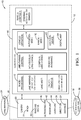
Fig. 1 is a diagram of a lane-change system in accordance with one embodiment; and -
Fig. 2 is a traffic-scenario encountered by the system ofFig. 1 in accordance with one embodiment. -
Fig. 1 illustrates a non-limiting example of a lane-change system 10, hereafter referred to as thesystem 10, which is suitable for use on an automated-vehicle, for example a host-vehicle 12. The examples presented herein are generally directed to instances when the host-vehicle 12 is being operated in an automated-mode 14, i.e. a fully autonomous mode, where a human operator (not shown) of the host-vehicle 12 may do little more than designate a destination in order to operate the host-vehicle 12. However, it is contemplated that the teachings presented herein are useful when the host-vehicle 12 is operated in a manual-mode 16 where the degree or level of automation may be little more than providing steering advice to the human operator who is generally in control of the steering, accelerator, and brakes of the host-vehicle 12. For example, thesystem 10 may merely assist the human operator as needed to change lanes and/or avoid interference and/or a collision with, for example, an other-vehicle 18. - The
system 10 includes a camera 20 (e.g. a video camera) used to detect animage 22 of a lane-marking 24 (see alsoFig. 2 ) on aroadway 26 traveled by the host-vehicle 12. There are many examples of commercially available cameras suitable for use on the host-vehicle 12 for detecting the lane-marking 24, as will be recognized by those in the art. Thecamera 20 may be mounted, for example, behind thewindshield 28 of the host-vehicle 12 so that windshield-wipers can be used to keep the view of thecamera 20 clear. Alternatively, thecamera 20 may be one of multiple cameras mounted at various strategic locations about the host-vehicle 12, for example at the corners of the body, or on the side-view mirrors of the host-vehicle 12. Multiple instances of thecamera 20 at multiple strategic locations on the host-vehicle 12 can provide for a better image of the lane-marking 24 and/or other objects proximate to the host-vehicle 12 when the host-vehicle 12 is close behind the other-vehicle 18. - The
system 10 also includes a ranging-device 30 used to determine adistance 32 and/or adirection 34 from the host-vehicle 12 to, for example, the other-vehicle 18, a guard-rail 36, or other object proximate to the host-vehicle12. Non-limiting examples of devices suitable to determine thedistance 32 and/or thedirection 34 to an object, and thereby form the ranging-device 30, include one or more instances of an ultrasonic-transducer 40, a radar-unit 42, and/or a lidar-unit 44, in any combination. As suggested above, the devices that form the ranging-device 30 and the one or more instances of thecamera 20 may cooperate to provide the means for 360 degree (i.e. surround) detection around the host-vehicle 12. - The
system 10 also includes acontroller 46 in communication with thecamera 20 and the ranging-device 30. Thecontroller 46 may include a processor (not specifically shown) such as a microprocessor or other control circuitry such as analog and/or digital control circuitry including an application specific integrated circuit (ASIC) for processing data as should be evident to those in the art. Thecontroller 46 may include memory (not specifically shown), including non-volatile memory, such as electrically erasable programmable read-only memory (EEPROM) for storing one or more routines, thresholds, and captured data. The one or more routines may be executed by the processor to perform steps for determining the relative position of the lane-marking 24 and the other-vehicle 18 based on signals received by thecontroller 46 from thecamera 20 and the ranging-device 30 as described herein. - The
controller 46 is in communication the vehicle-controls 48 of the host-vehicle 12 so the controller can operate or assist with operation of the steering, accelerator (accelerator pedal) and/or brakes (brake pedal) of the host-vehicle 12. The communication may be by way of wires via a vehicle-network, wireless communication, or other known means. In order enable particular aspects of thesystem 10, thecontroller 46 is programmed or configured to control a lane-change 50 by the host-vehicle 12 in accordance with theimage 22 when the lane-marking 24 is detected, and control the lane-change 50 in accordance with thedistance 32 and/or thedirection 34 to the other-vehicle 18 when the lane-marking 24 is not detected. For example, if the lane-marking unexpectedly disappears from theimage 22 after the lane-change 50 has been initiated, thecontroller 46 relies on information from the ranging-device 30 to operate (e.g. steer) the host-vehicle 12. Alternatively, or if information from the ranging-device is inadequate, thecontroller 46 may elect to switch into the manual-mode 16 to have the operator (not shown) of the host-vehicle 12 take control of the host-vehicle 12 until the lane-marking 24 is again detected. Further details of how thecontroller 46 controls the lane-change 50 when the lane-marking is not detected are given below. - However, a first step of preventing or avoiding the situation of having to rely on the ranging-
device 30 to operate the host-vehicle 12 may be to prevent initiation of the lane-change 50 when the lane-marking 24 is not detected at the moment of initiation. That said, if the lane-change 50 has already been initiated, e.g. the host-vehicle 12 is straddling the dashed-line 52 (Fig. 2 ) of theroadway 26 at the instant the lane-marking 24 unexpectedly disappears, but there is sufficient information from the ranging-device 30, e.g. the other-vehicle 18 has been well tracked for at least several seconds, then thecontroller 46 may be configured to complete the lane-change 50 in accordance with thedistance 32 and thedirection 34 to the other-vehicle 18 when the lane-marking 24 disappears after the lane-change 50 has been initiated. -
Fig. 2 illustrates a non-limiting example of a traffic-scenario 54 that the host-vehicle 12 may encounter where the host-vehicle 12 is traveling directly behind the other-vehicle 18, and the host-vehicle 12 is about to pass theother vehicle 18 using an adjacent-lane 56 of theroadway 26. By way of example and not limitation, in order to perform a passing maneuver, thecontroller 46 may be configured to project or determine a travel-path 58 of the other-vehicle 18 based on thedistance 32 and thedirection 34 to the other-vehicle 18. Thecontroller 46 may also determine or estimate a present speed of the other-vehicle 18 based on a range-rate detected using the ranging-device 30 and the present speed of the host-vehicle 12. - In this example, the travel-
path 58 is projected to be straight because the other-vehicle 18 has been traveling in a straight line for an extended period of time, e.g. more than twenty-five seconds (25s) for example. Alternatively or additionally, thecontroller 46 may be equipped with a location-device 62 such as a global-positioning-system (GPS) receiver, and have access to a digital-map 64 so that the future straight travel of the other-vehicle 18 may be more reliably projected. Thecontroller 46 may then control the host-vehicle 12 during the lane-change 50 into a parallel-path 60 characterized as parallel to travel-path 58 when the lane-marking 24 disappears after the lane-change 50 has been initiated. - In this example the parallel-
path 60 can be described as beside or offset from the travel-path 58, and is generally parallel to the travel-path 58. Thesystem 10, or more specifically thecontroller 46, uses the other-vehicle 18 as a guide or reference to steer the host-vehicle 12 along the parallel-path 60 by maintaining an offset-distance 66 relative to the other-vehicle 18 and/or the travel-path 58 when the lane-marking 24 is unavailable for use. The offset-distance 66 may be calculated from theimage 22 prior to the disappearance of the lane-marking 24, where theimage 22 indicates a lane-width 68 of theroadway 26, e.g. the lane-width 68 of the adjacent-lane 56 and/or the lane traveled by the other-vehicle 18. Then the offset-distance 66 that the parallel-path 60 is offset from the travel-path 58 may be calculated based on the lane-width 68. Alternatively, the lane-width 68 may be based on data from the digital-map 64. It is contemplated that if theroadway 26 is curved, the travel-path 58 would become curved as the other-vehicle 18 turned to follow the curve, and the parallel-path 60 would be appropriately curved to maintain the offset-distance 66 through the curve. - It is further contemplated that the parallel-
path 60 could be coincident with the travel-path 58, i.e. the same. For example, if the lane-change 50 was initiated, but the lane-marking 24 disappeared before the host-vehicle 12 had crossed the dashed-line 52, thecontroller 46 may be configured or programmed to abort the lane-change 50 and return to a location directly behind the other-vehicle 18 and thereby follow the travel-path 58 rather than move into the adjacent-lane 56. - In another embodiment of the
system 10, the ranging-device30 may be used or further configure to detect a guard-rail 36 adjacent to theroadway 26, and thecontroller 46 may be configured to avoid an instance of the host-vehicle 12 making contact with the guard-rail 36 during the lane-change 50. For example, if the guard-rail 36 is too close to the dashed-line 52 (or a solid-line at the same location), e.g. less than three meters (3m), it may be an indication that what appears to be the adjacent-lane 56 is actually a shoulder of theroadway 26. It follows that thecontroller 46 would not initiate the lane-change 50. - Accordingly, a lane-change system (the system 10), a
controller 46 for thesystem 10, and a method of operating thesystem 10 is provided. Thesystem 10 overcomes problems that arise when the lane-marking 24 unexpectedly disappears due to, for example, construction, or age of the lane-marking 24. - While this invention has been described in terms of the preferred embodiments thereof, it is not intended to be so limited, but rather only to the extent set forth in the claims that follow.
Claims (6)
- A lane-change system (10) suitable for use on an automated-vehicle, said system (10) comprising:a camera (20) used to detect an image (22) of a lane-marking (24) on a roadway (26) traveled by a host-vehicle (12);a ranging-device (30) used to determine a distance (32) and a direction (34) from the host-vehicle (12) to an other-vehicle (18) proximate to the host-vehicle (12);a controller (46) in communication with the camera (20) and the ranging-device (30), said controller (46) configured to control a lane-change (50) by the host-vehicle (12) in accordance with the image (22) when the lane-marking (24) is detected, and control the lane-change (50) in accordance with the distance (32) and the direction (34) to the other-vehicle (18) when the lane-marking (24) is not detected.
- The system (10) in accordance with claim 1, wherein the ranging-device (30) is one or more of an ultrasonic-transducer (40), a radar-unit (42), and a lidar-unit (44).
- The system (10) according to any one of the preceding claims, wherein the controller (46) is configured to prevent initiation of the lane-change (50) when the lane-marking (24) is not detected, and complete the lane-change (50) in accordance with the distance (32) and the direction (34) to the other-vehicle (18) when the lane-marking (24) disappears after the lane-change (50) has been initiated.
- The system (10) according to any one of the preceding claims, wherein the controller (46) is configured to determine a travel-path (58) of the other-vehicle (18) based on the distance (32) and the direction (34) to the other-vehicle (18), and control the host-vehicle (12) during the lane-change (50) into a parallel-path (60) characterized as parallel to travel-path (58) when the lane-marking (24) disappears after the lane-change (50) has been initiated.
- The system (10) in accordance with claim 4, wherein the image (22) indicates a lane-width (68) of the roadway (26), and the parallel-path (60) is offset from the travel-path (58) by the lane-width (68).
- The system (10) according to any one of the preceding claims, wherein the ranging-device (30) is further configure to detect a guard-rail (36) adjacent to the roadway (26), and the controller (46) is configured to avoid the host-vehicle (12) making contact with the guard-rail (36) during the lane-change (50).
Applications Claiming Priority (1)
| Application Number | Priority Date | Filing Date | Title |
|---|---|---|---|
| US15/257,081 US20180067496A1 (en) | 2016-09-06 | 2016-09-06 | Automated vehicle lane change control system |
Publications (1)
| Publication Number | Publication Date |
|---|---|
| EP3291136A1 true EP3291136A1 (en) | 2018-03-07 |
Family
ID=59772392
Family Applications (1)
| Application Number | Title | Priority Date | Filing Date |
|---|---|---|---|
| EP17187266.6A Ceased EP3291136A1 (en) | 2016-09-06 | 2017-08-22 | Automated vehicle lane change control system |
Country Status (3)
| Country | Link |
|---|---|
| US (1) | US20180067496A1 (en) |
| EP (1) | EP3291136A1 (en) |
| CN (1) | CN107792068B (en) |
Cited By (1)
| Publication number | Priority date | Publication date | Assignee | Title |
|---|---|---|---|---|
| US11097747B2 (en) * | 2018-03-27 | 2021-08-24 | Nissan Motor Co., Ltd. | Method and device for controlling autonomously driven vehicle |
Families Citing this family (16)
| Publication number | Priority date | Publication date | Assignee | Title |
|---|---|---|---|---|
| JP6524943B2 (en) * | 2016-03-17 | 2019-06-05 | 株式会社デンソー | Driving support device |
| RU2727907C1 (en) * | 2017-04-12 | 2020-07-24 | Ниссан Мотор Ко., Лтд. | Driving control method and driving control device |
| US10466706B2 (en) * | 2017-08-14 | 2019-11-05 | Aptiv Technologies Limited | Automated guidance system |
| US10895460B2 (en) * | 2017-11-06 | 2021-01-19 | Cybernet Systems Corporation | System and method for generating precise road lane map data |
| US10614320B2 (en) * | 2018-04-03 | 2020-04-07 | Honda Motor Co., Ltd. | System and method for advanced highway lane detection |
| US10656647B2 (en) * | 2018-06-27 | 2020-05-19 | Aptiv Technologies Limited | Verification of vehicle operator awareness before transition from autonomous-mode to manual-mode |
| CN110641464B (en) * | 2018-06-27 | 2023-06-06 | 德尔福技术有限公司 | Camera Adjustment System |
| US20200049513A1 (en) * | 2018-08-10 | 2020-02-13 | Delphi Technologies, Llc | Positioning system |
| US10940863B2 (en) * | 2018-11-01 | 2021-03-09 | GM Global Technology Operations LLC | Spatial and temporal attention-based deep reinforcement learning of hierarchical lane-change policies for controlling an autonomous vehicle |
| CN109624972B (en) * | 2018-12-06 | 2020-06-09 | 北京百度网讯科技有限公司 | Method, device and equipment for preventing vehicle from collision and readable storage medium |
| JP6966489B2 (en) * | 2019-01-17 | 2021-11-17 | 本田技研工業株式会社 | Vehicle control systems, vehicle control methods, and programs |
| US11548511B2 (en) * | 2019-06-14 | 2023-01-10 | GM Global Technology Operations LLC | Method to control vehicle speed to center of a lane change gap |
| CN110969900B (en) * | 2019-11-21 | 2022-03-15 | 中国航空工业集团公司西安飞行自动控制研究所 | All-lane horizontal offset calculation method based on lane management |
| US11491985B2 (en) * | 2019-11-26 | 2022-11-08 | GM Global Technology Operations LLC | Process and system for sensor sharing for an autonomous lane change |
| US12017649B2 (en) | 2020-09-25 | 2024-06-25 | Ford Global Technologies, Llc | Blockchain system to aid vehicle actions |
| US20220379922A1 (en) * | 2021-06-01 | 2022-12-01 | Denso International America, Inc. | System for maneuvering a vehicle |
Citations (7)
| Publication number | Priority date | Publication date | Assignee | Title |
|---|---|---|---|---|
| US20090212930A1 (en) * | 2005-03-03 | 2009-08-27 | Continental Teves Ag & Co. Ohg | Method and Device for Avoiding a Collision in a Lane Change Maneuver of a Vehicle |
| US20110044507A1 (en) * | 2008-02-20 | 2011-02-24 | Continetalteves Ag & Co. Ohg | Method and assistance system for detecting objects in the surrounding area of a vehicle |
| US8504233B1 (en) * | 2012-04-27 | 2013-08-06 | Google Inc. | Safely navigating on roads through maintaining safe distance from other vehicles |
| US20140306844A1 (en) * | 2013-04-11 | 2014-10-16 | Mando Corporation | Lane estimation apparatus and method |
| US20140324325A1 (en) * | 2013-04-26 | 2014-10-30 | Conti Temic Microelectronic Gmbh | Method and Device for Estimating the Number of Lanes and/or the Lane Width on a Roadway |
| US8880273B1 (en) * | 2013-01-16 | 2014-11-04 | Google Inc. | System and method for determining position and distance of objects using road fiducials |
| WO2016104042A1 (en) * | 2014-12-26 | 2016-06-30 | 日立オートモティブシステムズ株式会社 | Vehicle control system |
Family Cites Families (4)
| Publication number | Priority date | Publication date | Assignee | Title |
|---|---|---|---|---|
| JP5124875B2 (en) * | 2008-03-12 | 2013-01-23 | 本田技研工業株式会社 | Vehicle travel support device, vehicle, vehicle travel support program |
| CN203753005U (en) * | 2013-11-19 | 2014-08-06 | 浙江吉利汽车研究院有限公司 | Lane departure warning device |
| JP6141787B2 (en) * | 2014-04-01 | 2017-06-07 | 本田技研工業株式会社 | Lane mark recognition device |
| CN104318761B (en) * | 2014-08-29 | 2017-02-08 | 华南理工大学 | Highway-scene-based detection and vehicle detection tracking optimization method |
-
2016
- 2016-09-06 US US15/257,081 patent/US20180067496A1/en not_active Abandoned
-
2017
- 2017-08-22 EP EP17187266.6A patent/EP3291136A1/en not_active Ceased
- 2017-09-05 CN CN201710790208.1A patent/CN107792068B/en active Active
Patent Citations (7)
| Publication number | Priority date | Publication date | Assignee | Title |
|---|---|---|---|---|
| US20090212930A1 (en) * | 2005-03-03 | 2009-08-27 | Continental Teves Ag & Co. Ohg | Method and Device for Avoiding a Collision in a Lane Change Maneuver of a Vehicle |
| US20110044507A1 (en) * | 2008-02-20 | 2011-02-24 | Continetalteves Ag & Co. Ohg | Method and assistance system for detecting objects in the surrounding area of a vehicle |
| US8504233B1 (en) * | 2012-04-27 | 2013-08-06 | Google Inc. | Safely navigating on roads through maintaining safe distance from other vehicles |
| US8880273B1 (en) * | 2013-01-16 | 2014-11-04 | Google Inc. | System and method for determining position and distance of objects using road fiducials |
| US20140306844A1 (en) * | 2013-04-11 | 2014-10-16 | Mando Corporation | Lane estimation apparatus and method |
| US20140324325A1 (en) * | 2013-04-26 | 2014-10-30 | Conti Temic Microelectronic Gmbh | Method and Device for Estimating the Number of Lanes and/or the Lane Width on a Roadway |
| WO2016104042A1 (en) * | 2014-12-26 | 2016-06-30 | 日立オートモティブシステムズ株式会社 | Vehicle control system |
Cited By (1)
| Publication number | Priority date | Publication date | Assignee | Title |
|---|---|---|---|---|
| US11097747B2 (en) * | 2018-03-27 | 2021-08-24 | Nissan Motor Co., Ltd. | Method and device for controlling autonomously driven vehicle |
Also Published As
| Publication number | Publication date |
|---|---|
| US20180067496A1 (en) | 2018-03-08 |
| CN107792068A (en) | 2018-03-13 |
| CN107792068B (en) | 2020-04-21 |
Similar Documents
| Publication | Publication Date | Title |
|---|---|---|
| US20180067496A1 (en) | Automated vehicle lane change control system | |
| JP6930600B2 (en) | Vehicle position estimation device and vehicle control device | |
| EP3477614B1 (en) | Vehicle control method and vehicle control device | |
| EP3179270A1 (en) | Lane extension of lane-keeping system by ranging-sensor for automated vehicle | |
| US10513267B2 (en) | Vehicle safety system | |
| EP1395851B1 (en) | Sensing apparatus for vehicles | |
| EP3608635A1 (en) | Positioning system | |
| CN109388139B (en) | Automatic guiding system | |
| US12305992B2 (en) | Vehicle perception-data gathering system and method | |
| CN107688894A (en) | Automotive vehicles operation person's technical capability evaluation system | |
| EP3501932B1 (en) | Automated vehicle system and method for changing from automated-mode to manual-mode near a construction-zone | |
| CN114526747B (en) | Lane extension for automated vehicles using vision-based steering | |
| EP3431929A1 (en) | Automated vehicle guidance system | |
| US20170349181A1 (en) | Lane management system for an automated vehicle | |
| CN108572644B (en) | Lane change system for automated vehicles | |
| JP2020006719A (en) | Automatic test travel system for traveling vehicle | |
| EP3316233B1 (en) | Automated vehicle cross-traffic detection system | |
| EP3581467B1 (en) | Object tracking after object turns off host-vehicle roadway | |
| US20230001924A1 (en) | Method for Operating a Vehicle and Device for Carrying Out the Method |
Legal Events
| Date | Code | Title | Description |
|---|---|---|---|
| PUAI | Public reference made under article 153(3) epc to a published international application that has entered the european phase |
Free format text: ORIGINAL CODE: 0009012 |
|
| STAA | Information on the status of an ep patent application or granted ep patent |
Free format text: STATUS: THE APPLICATION HAS BEEN PUBLISHED |
|
| AK | Designated contracting states |
Kind code of ref document: A1 Designated state(s): AL AT BE BG CH CY CZ DE DK EE ES FI FR GB GR HR HU IE IS IT LI LT LU LV MC MK MT NL NO PL PT RO RS SE SI SK SM TR |
|
| AX | Request for extension of the european patent |
Extension state: BA ME |
|
| STAA | Information on the status of an ep patent application or granted ep patent |
Free format text: STATUS: REQUEST FOR EXAMINATION WAS MADE |
|
| 17P | Request for examination filed |
Effective date: 20180907 |
|
| RBV | Designated contracting states (corrected) |
Designated state(s): AL AT BE BG CH CY CZ DE DK EE ES FI FR GB GR HR HU IE IS IT LI LT LU LV MC MK MT NL NO PL PT RO RS SE SI SK SM TR |
|
| RAP1 | Party data changed (applicant data changed or rights of an application transferred) |
Owner name: APTIV TECHNOLOGIES LIMITED |
|
| STAA | Information on the status of an ep patent application or granted ep patent |
Free format text: STATUS: EXAMINATION IS IN PROGRESS |
|
| 17Q | First examination report despatched |
Effective date: 20201013 |
|
| RAP3 | Party data changed (applicant data changed or rights of an application transferred) |
Owner name: APTIV TECHNOLOGIES LIMITED |
|
| STAA | Information on the status of an ep patent application or granted ep patent |
Free format text: STATUS: THE APPLICATION HAS BEEN REFUSED |
|
| 18R | Application refused |
Effective date: 20230224 |