US11491985B2 - Process and system for sensor sharing for an autonomous lane change - Google Patents
Process and system for sensor sharing for an autonomous lane change Download PDFInfo
- Publication number
- US11491985B2 US11491985B2 US16/695,897 US201916695897A US11491985B2 US 11491985 B2 US11491985 B2 US 11491985B2 US 201916695897 A US201916695897 A US 201916695897A US 11491985 B2 US11491985 B2 US 11491985B2
- Authority
- US
- United States
- Prior art keywords
- host vehicle
- vehicle
- sensors
- lane
- confederate
- Prior art date
- Legal status (The legal status is an assumption and is not a legal conclusion. Google has not performed a legal analysis and makes no representation as to the accuracy of the status listed.)
- Active, expires
Links
- 238000000034 method Methods 0.000 title claims abstract description 157
- 238000004891 communication Methods 0.000 claims abstract description 44
- 238000012544 monitoring process Methods 0.000 claims abstract description 18
- 230000008447 perception Effects 0.000 claims description 90
- 230000000694 effects Effects 0.000 claims description 11
- 238000001514 detection method Methods 0.000 claims description 3
- 239000003550 marker Substances 0.000 description 5
- 230000001133 acceleration Effects 0.000 description 4
- 238000013461 design Methods 0.000 description 3
- 230000003044 adaptive effect Effects 0.000 description 2
- 230000000903 blocking effect Effects 0.000 description 2
- 230000007613 environmental effect Effects 0.000 description 2
- 230000000977 initiatory effect Effects 0.000 description 2
- 230000001413 cellular effect Effects 0.000 description 1
- 238000013480 data collection Methods 0.000 description 1
- 238000013500 data storage Methods 0.000 description 1
- 230000003247 decreasing effect Effects 0.000 description 1
- 238000005516 engineering process Methods 0.000 description 1
- 230000005055 memory storage Effects 0.000 description 1
- 230000011664 signaling Effects 0.000 description 1
Images


Classifications
-
- B—PERFORMING OPERATIONS; TRANSPORTING
- B60—VEHICLES IN GENERAL
- B60W—CONJOINT CONTROL OF VEHICLE SUB-UNITS OF DIFFERENT TYPE OR DIFFERENT FUNCTION; CONTROL SYSTEMS SPECIALLY ADAPTED FOR HYBRID VEHICLES; ROAD VEHICLE DRIVE CONTROL SYSTEMS FOR PURPOSES NOT RELATED TO THE CONTROL OF A PARTICULAR SUB-UNIT
- B60W30/00—Purposes of road vehicle drive control systems not related to the control of a particular sub-unit, e.g. of systems using conjoint control of vehicle sub-units, or advanced driver assistance systems for ensuring comfort, stability and safety or drive control systems for propelling or retarding the vehicle
- B60W30/18—Propelling the vehicle
- B60W30/18009—Propelling the vehicle related to particular drive situations
- B60W30/18163—Lane change; Overtaking manoeuvres
-
- B—PERFORMING OPERATIONS; TRANSPORTING
- B60—VEHICLES IN GENERAL
- B60W—CONJOINT CONTROL OF VEHICLE SUB-UNITS OF DIFFERENT TYPE OR DIFFERENT FUNCTION; CONTROL SYSTEMS SPECIALLY ADAPTED FOR HYBRID VEHICLES; ROAD VEHICLE DRIVE CONTROL SYSTEMS FOR PURPOSES NOT RELATED TO THE CONTROL OF A PARTICULAR SUB-UNIT
- B60W40/00—Estimation or calculation of non-directly measurable driving parameters for road vehicle drive control systems not related to the control of a particular sub unit, e.g. by using mathematical models
- B60W40/12—Estimation or calculation of non-directly measurable driving parameters for road vehicle drive control systems not related to the control of a particular sub unit, e.g. by using mathematical models related to parameters of the vehicle itself, e.g. tyre models
-
- G—PHYSICS
- G01—MEASURING; TESTING
- G01S—RADIO DIRECTION-FINDING; RADIO NAVIGATION; DETERMINING DISTANCE OR VELOCITY BY USE OF RADIO WAVES; LOCATING OR PRESENCE-DETECTING BY USE OF THE REFLECTION OR RERADIATION OF RADIO WAVES; ANALOGOUS ARRANGEMENTS USING OTHER WAVES
- G01S13/00—Systems using the reflection or reradiation of radio waves, e.g. radar systems; Analogous systems using reflection or reradiation of waves whose nature or wavelength is irrelevant or unspecified
- G01S13/88—Radar or analogous systems specially adapted for specific applications
- G01S13/93—Radar or analogous systems specially adapted for specific applications for anti-collision purposes
- G01S13/931—Radar or analogous systems specially adapted for specific applications for anti-collision purposes of land vehicles
-
- G—PHYSICS
- G01—MEASURING; TESTING
- G01S—RADIO DIRECTION-FINDING; RADIO NAVIGATION; DETERMINING DISTANCE OR VELOCITY BY USE OF RADIO WAVES; LOCATING OR PRESENCE-DETECTING BY USE OF THE REFLECTION OR RERADIATION OF RADIO WAVES; ANALOGOUS ARRANGEMENTS USING OTHER WAVES
- G01S17/00—Systems using the reflection or reradiation of electromagnetic waves other than radio waves, e.g. lidar systems
- G01S17/88—Lidar systems specially adapted for specific applications
- G01S17/93—Lidar systems specially adapted for specific applications for anti-collision purposes
- G01S17/931—Lidar systems specially adapted for specific applications for anti-collision purposes of land vehicles
-
- H—ELECTRICITY
- H04—ELECTRIC COMMUNICATION TECHNIQUE
- H04W—WIRELESS COMMUNICATION NETWORKS
- H04W4/00—Services specially adapted for wireless communication networks; Facilities therefor
- H04W4/30—Services specially adapted for particular environments, situations or purposes
- H04W4/40—Services specially adapted for particular environments, situations or purposes for vehicles, e.g. vehicle-to-pedestrians [V2P]
- H04W4/46—Services specially adapted for particular environments, situations or purposes for vehicles, e.g. vehicle-to-pedestrians [V2P] for vehicle-to-vehicle communication [V2V]
-
- B60W2420/408—
-
- B—PERFORMING OPERATIONS; TRANSPORTING
- B60—VEHICLES IN GENERAL
- B60W—CONJOINT CONTROL OF VEHICLE SUB-UNITS OF DIFFERENT TYPE OR DIFFERENT FUNCTION; CONTROL SYSTEMS SPECIALLY ADAPTED FOR HYBRID VEHICLES; ROAD VEHICLE DRIVE CONTROL SYSTEMS FOR PURPOSES NOT RELATED TO THE CONTROL OF A PARTICULAR SUB-UNIT
- B60W2420/00—Indexing codes relating to the type of sensors based on the principle of their operation
- B60W2420/54—Audio sensitive means, e.g. ultrasound
-
- B—PERFORMING OPERATIONS; TRANSPORTING
- B60—VEHICLES IN GENERAL
- B60W—CONJOINT CONTROL OF VEHICLE SUB-UNITS OF DIFFERENT TYPE OR DIFFERENT FUNCTION; CONTROL SYSTEMS SPECIALLY ADAPTED FOR HYBRID VEHICLES; ROAD VEHICLE DRIVE CONTROL SYSTEMS FOR PURPOSES NOT RELATED TO THE CONTROL OF A PARTICULAR SUB-UNIT
- B60W2554/00—Input parameters relating to objects
- B60W2554/80—Spatial relation or speed relative to objects
-
- B—PERFORMING OPERATIONS; TRANSPORTING
- B60—VEHICLES IN GENERAL
- B60W—CONJOINT CONTROL OF VEHICLE SUB-UNITS OF DIFFERENT TYPE OR DIFFERENT FUNCTION; CONTROL SYSTEMS SPECIALLY ADAPTED FOR HYBRID VEHICLES; ROAD VEHICLE DRIVE CONTROL SYSTEMS FOR PURPOSES NOT RELATED TO THE CONTROL OF A PARTICULAR SUB-UNIT
- B60W2555/00—Input parameters relating to exterior conditions, not covered by groups B60W2552/00, B60W2554/00
- B60W2555/60—Traffic rules, e.g. speed limits or right of way
-
- B—PERFORMING OPERATIONS; TRANSPORTING
- B60—VEHICLES IN GENERAL
- B60W—CONJOINT CONTROL OF VEHICLE SUB-UNITS OF DIFFERENT TYPE OR DIFFERENT FUNCTION; CONTROL SYSTEMS SPECIALLY ADAPTED FOR HYBRID VEHICLES; ROAD VEHICLE DRIVE CONTROL SYSTEMS FOR PURPOSES NOT RELATED TO THE CONTROL OF A PARTICULAR SUB-UNIT
- B60W2556/00—Input parameters relating to data
- B60W2556/45—External transmission of data to or from the vehicle
- B60W2556/65—Data transmitted between vehicles
Definitions
- the disclosure generally relates to a process and system for sensor sharing for an autonomous lane change.
- Autonomous lane changing is a control process whereby a computerized processor autonomously or semi-autonomously controls operation of a vehicle.
- Sensor data is useful to provide information to the autonomous lane changing control process.
- Sensor data may come from a wide variety of sensors, including but not limited to a camera, a radar device, a LIDAR device, and an ultrasonic sensor device.
- Control processes implemented by autonomous lane changing may include but are not limited to lane keeping, adaptive cruise control, obstacle avoidance, and automatic lane changing.
- vehicle to vehicle communication is possible, with maximum vehicle to vehicle communication ranges varying upon particular hardware configurations.
- communication through dedicated short-range communications (DSRC) is possible, for example, with one vehicle providing information wirelessly to a second vehicle through a dedicated roadside unit providing a secure wireless connection similar to WiFi.
- communication through a wireless cloud network is possible, for example, with one vehicle providing information wirelessly to a remote server device and with a second vehicle accessing the data wirelessly from the remote server device.
- a process for sensor sharing for an autonomous lane change includes, within a dynamic controller of a host vehicle, monitoring sensors of the host vehicle, establishing communication between the host vehicle and a confederate vehicle on a same roadway as the host vehicle, monitoring sensors of the confederate vehicle, within the dynamic controller of the host vehicle, utilizing data from the sensors of the host vehicle and data from the sensors of the confederate vehicle to initiate a lane change maneuver for the host vehicle, and executing the lane change maneuver for the host vehicle.
- establishing the communication between the host vehicle and the confederate vehicle includes establishing direct vehicle to vehicle communication.
- establishing the communication between the host vehicle and the confederate vehicle includes communicating through a wireless network.
- utilizing the data from the sensors of the host vehicle and the data from the sensors of the confederate vehicle to initiate the lane change maneuver for the host vehicle includes selecting a calculated perception range to initiate the lane change maneuver and determining whether an effective sensor range of the sensors of the host vehicle and an effective sensor range of the sensors of the confederate vehicle together cover the calculated perception range.
- determining whether the effective sensor range of the sensors of the host vehicle and the effective sensor range of the sensors of the confederate vehicle together cover the calculated perception range includes determining an effect of a third vehicle obscuring the sensors of the host vehicle.
- determining whether the effective sensor range of the sensors of the host vehicle and the effective sensor range of the sensors of the confederate vehicle together cover the calculated perception range further includes determining an effect of the third vehicle obscuring the sensors of the confederate vehicle.
- determining whether the effective sensor range of the sensors of the host vehicle and the effective sensor range of the sensors of the confederate vehicle together cover the calculated perception range includes determining an effect of a trailer being towed by the host vehicle obscuring the sensors of the host vehicle.
- selecting the calculated perception range to initiate the lane change maneuver includes determining a time to achieve a target speed at a completion of the lane change maneuver.
- selecting the calculated perception range includes adding an offset value.
- utilizing the data from the sensors of the host vehicle and the data from the sensors of the confederate vehicle to initiate the lane change maneuver for the host vehicle includes comparing an absolute value of an initial speed of the host vehicle minus a determination lane speed limit plus an offset value to a calibration value and declining to initiate the lane change maneuver based upon the comparing.
- the host vehicle is initially traveling in a first lane upon the roadway, and executing the lane change maneuver for the host vehicle includes moving the host vehicle into a second lane upon the roadway.
- monitoring the sensors of the host vehicle includes detecting an oversized vehicle upon the roadway, the host vehicle is initially traveling in a first lane upon the roadway, and executing the lane change maneuver for the host vehicle includes moving the host vehicle to one side of the first lane based upon maintaining an offset from the oversized vehicle.
- the process further includes determining an effect of a trailer being towed by the host vehicle obscuring the sensors of the host vehicle.
- the confederate vehicle is rearward of the host vehicle.
- the confederate vehicle is forward of the host vehicle.
- a process for sensor sharing for an autonomous lane change includes, within a dynamic controller of a host vehicle, monitoring sensors of the host vehicle, establishing communication between the host vehicle and a confederate vehicle on a same roadway as the host vehicle through a wireless network, monitoring sensors of the confederate vehicle, within the dynamic controller of the host vehicle, utilizing data from the sensors of the host vehicle and data from the sensors of the confederate vehicle to initiate a lane change maneuver for the host vehicle.
- the utilizing includes selecting a calculated perception range to initiate the lane change maneuver and determining whether an effective sensor range of the sensors of the host vehicle and an effective sensor range of the sensors of the confederate vehicle together cover the calculated perception range.
- the process further includes executing the lane change maneuver for the host vehicle.
- determining whether the effective sensor range of the sensors of the host vehicle and the effective sensor range of the sensors of the confederate vehicle together cover the calculated perception range includes determining an effect of a third vehicle obscuring the sensors of the host vehicle.
- a system for sensor sharing for an autonomous lane change includes a host vehicle traveling upon a roadway and including a first sensor configured to monitor the roadway, a confederate vehicle traveling upon the roadway including a second sensor configured to monitor the roadway, a communication link between the host vehicle and the confederate vehicle, and a computerized dynamic controller within the host vehicle.
- the computerized dynamic controller is programmed to monitor data from the first sensor, monitor data from the second sensor through the communication link, utilize the data from the first sensor and the data from the second sensor to initiate a lane change maneuver for the host vehicle, and authorizing the lane change maneuver for the host vehicle.
- the host vehicle includes a towed trailer
- the computerized dynamic controller evaluates an effect of the towed trailer upon the data from the first sensor.
- utilizing the data from the first sensor and the data from the second sensor to initiate the lane change maneuver for the host vehicle includes selecting a calculated perception range to initiate the lane change maneuver and determining whether an effective sensor range of the sensors of the host vehicle and an effective sensor range of the sensors of the confederate vehicle together cover the calculated perception range.
- FIG. 1 illustrates an exemplary host vehicle upon a roadway utilizing data from a confederate vehicle behind the host vehicle to classify a portion of a destination lane as clear for a desired lane change, in accordance with the present disclosure
- FIG. 2 schematically illustrates an exemplary vehicle system configuration useful to enable operation of the disclosed process to share vehicle data, in accordance with the present disclosure
- FIG. 3 is a flowchart illustrating an exemplary process operable to execute the desired lane change illustrated in FIG. 1 , in accordance with the present disclosure
- FIG. 4 schematically illustrates an exemplary vehicle including hardware and devices useful to execute the disclosed processes, in accordance with the present disclosure
- FIG. 5 illustrates an alternative exemplary host vehicle upon a roadway utilizing data from a confederate vehicle to classify a portion of a destination lane as clear for a desired lane change, wherein a third vehicle is situated in a position that partially obscures the on-board sensors of the host vehicle, in accordance with the present disclosure
- FIG. 6 is a flowchart illustrating an exemplary process operable to execute the desired lane change illustrated in FIG. 5 , in accordance with the present disclosure
- FIG. 7 illustrates an alternative exemplary host vehicle upon a roadway utilizing data from a confederate vehicle to classify a portion of a destination lane as clear for a desired lane change, wherein the host vehicle includes a trailer, in accordance with the present disclosure
- FIG. 8 is a flowchart illustrating an exemplary process operable to execute the desired lane change illustrated in FIG. 7 , in accordance with the present disclosure
- FIG. 9 illustrates an alternative exemplary host vehicle upon a roadway utilizing data from a confederate vehicle to classify a portion of a destination lane as clear for a desired maneuver, wherein the host vehicle is utilizing an auxiliary control process of dynamic offset to maintain a minimum distance from an oversized vehicle, in accordance with the present disclosure
- FIG. 10 is a flowchart illustrating an exemplary process operable to execute the desired lane change illustrated in FIG. 9 , in accordance with the present disclosure
- FIG. 11 illustrates an alternative exemplary host vehicle upon a roadway utilizing data from a confederate vehicle ahead of the host to classify a portion of a destination lane as clear for a desired lane change, wherein a third vehicle is situated in a position that partially obscures the on-board sensors of the host vehicle, in accordance with the present disclosure
- FIG. 12 is a flowchart illustrating an exemplary process operable to execute the desired lane change illustrated in FIG. 11 , in accordance with the present disclosure
- FIG. 13 illustrates an alternative exemplary host vehicle upon a roadway utilizing data from a confederate vehicle to classify a portion of a destination lane as clear for a desired lane change, wherein a third vehicle is situated in a position that partially obscures the sensors of both the host vehicle and the confederate vehicle, in accordance with the present disclosure
- FIG. 14 is a flowchart illustrating an exemplary process operable to execute the desired lane change illustrated in FIG. 13 , in accordance with the present disclosure.
- a process and system for sensor sharing for autonomous lane changing is provided.
- a host vehicle may include programming commanding a desired lane change.
- a dynamic controller may include a computerized processor including programming operable to execute a lane change.
- the dynamic controller gains permission to execute the desired lane change by classifying as clear a portion of a destination lane into which a desired lane change is planned to occur.
- the dynamic controller may utilize on-board sensors to detect other vehicles within the portion of the destination lane as a basis for classifying the portion as clear or not-clear.
- a controller described herein may include a computerized device operable to execute programming.
- a controller may include a microprocessor, random access memory (RAM), durable memory providing for data storage, and an analog/digital converter operable to enable communication between the controller and a wide variety of electronic devices and sensors.
- Programming executed by the controller may include algorithms, instructions, computerized processes, and any other similar operations that may be performed by a computerized device.
- a controller may be a single device, may be a portion of a larger computerized device, or may span several devices.
- Multiple vehicles upon a roadway may simultaneously or contemporaneously utilize sensors to monitor portions of the roadway.
- a more complete map of the roadway may be populated, for example, utilizing sensor data from two or more vehicles to classify a portion of a destination lane as being clear.
- Vehicles may exchange data directly, for example, through vehicle to vehicle communication. Such communication may be established through radio or wireless communication technology, through use of infrastructure signaling systems, through light or laser communication, through short range wireless communication such as DSRC, or through other similar communication methods and systems in the art. Similarly, vehicles may exchange data through wireless communication through a remote server or a cloud network.
- multiple vehicles may provide location data to a cloud network
- a host vehicle seeking to make a lane change may query the location data to determine whether another vehicle is registered in a certain position upon a roadway, one of the registered vehicles in the certain location may be designated a confederate vehicle able to assist the host vehicle in gathering data about the roadway, and sensor data from the confederate vehicle may be made available to the host vehicle through the cloud network.
- the exemplary communication methods are provided as non-limiting examples, a number of alternative communication methods are envisioned, and the disclosure is not intended to be limited to the examples provided herein.
- FIG. 1 illustrates an exemplary host vehicle upon a roadway utilizing data from a confederate vehicle behind the host vehicle to classify a portion of a destination as clear for a desired lane change.
- Host vehicle 10 is illustrated upon roadway 40 following behind a slowly-moving second vehicle 20 .
- Roadway 40 includes a first lane 42 defined by boundary marker 41 and boundary marker 43 .
- Roadway 40 further includes a second lane 44 defined by boundary marker 43 and boundary marker 45 .
- Host vehicle 10 either by designation of a user within host vehicle 10 or through autonomous or semi-autonomous computerized methods operated therein or remotely on behalf of host vehicle 10 , has identified a desired lane change from first lane 42 to second lane 44 .
- Autonomous and semi-autonomous computerized methods for controlling a vehicle may include control over steering, acceleration, and braking.
- Autonomous and semi-autonomous computerized methods can be used for purposes of lane keeping, lane changing, adaptive cruise control, autonomous braking, obstacle avoidance, and other similar purposes.
- the required maneuver will include steering the host vehicle 10 laterally from first lane 42 into second lane 44 , and it will also include longitudinally accelerating second vehicle 20 to the rated speed of second lane 44 .
- a dynamic controller within host vehicle 10 may analyze available data from sensors monitoring second lane 44 to determine whether a portion of the second lane 44 to the right and rear of host vehicle 10 may be classified as clear.
- the second lane 44 may be described as the destination lane into which the desired lane change is to occur.
- the dynamic controller through use of programmed code and/or use of reference tables may determine 1) a size and geometry of the portion of the destination lane that is to be classified as clear and 2) whether the on-board sensors of the host vehicle are capable of providing data to accomplish classifying the portion of the destination lane as clear.
- the host vehicle may communicate with another vehicle, in the example of FIG. 1 , with confederate vehicle 30 .
- host vehicle 10 may utilize data from sensors of confederate vehicle 30 , in combination with data from on-board sensors of host vehicle 10 , to classify the portion of the second lane 44 as clear.
- a calculated perception range to initiate a lane change may in one embodiment depend upon time (T lx ) it takes host vehicle 10 to reach a target velocity.
- a target velocity may be set in a number of ways, for example, based upon a speed limit defining a maximum allowable speed or a lead vehicle speed which host vehicle 10 is being commanded to follow.
- a determination may be made whether or not to classify the portion of the destination lane as clear and whether to authorize the desired lane change.
- a factor of safety or an offset value may be utilized to increase a size of the calculated perception range and ensure orderly lane change maneuvers.
- effective perception ranges of one or more confederate vehicles may be analyzed and overlaid with the effective range of the host vehicle's sensors.
- the host vehicle and two separate confederate vehicles may be in positions to gather data regarding the calculated perception range; however, a gap might exist between the effective perception ranges which creates a “blind spot.”
- the disclosed processes may include an analysis and determination regarding whether a combination of the host vehicle's effective perception range and the effective perception range(s) of available confederate vehicle(s) adequately cover the calculated perception range and eliminate any blind spots.
- a calculated perception range may be used to define a portion of the destination lane that is to be classified as clear in order to enable initiation of a lane change maneuver.
- Effective perception range of a particular sensor may include a maximum design range, for example, a maximum range at which an object will return a discernable return signal to a radar sensor under perfect or laboratory conditions. Effective perception range can be decreased from the maximum design range by a number of factors. For example, fog or rain may impede an ability of a sensor to detect object out to a maximum range. In another example, objects may intervene between a sensor and an area of a road being monitored, for example, with a vehicle in traffic blocking or obscuring an entirety or a portion of a field of view of the sensor. Controllers within the host vehicle 10 and/or a confederate vehicle 30 may evaluate factors that affect the effective perception ranges of each of the sensors being monitored and determine effective perception ranges for each of the sensors, including environmental factors, obscuring factors, and other similar factors.
- controllers in the host vehicle 10 and/or a confederate vehicle 30 may individually or collectively determine 1) a road surface area in a destination lane that would be recommended to complete a lane change maneuver and 2) the effective perception ranges of sensors that would be recommended to classify the road surface area in the destination lane as clear such that the lane change maneuver may be initiated. If a gap or blind slot exists within the road surface area, wherein no available sensor is providing data regarding whether an obstacle exist within that blind spot, then the destination lane cannot be classified as clear.
- an exemplary effective perception range 12 of host vehicle 10 is illustrated in combination with an exemplary effective perception range 32 of confederate vehicle 30 , with effective perception range 12 and effective perception range 32 collectively covering a portion of second lane 44 and generating data useful to classify the portion of second lane 44 as clear.
- the portion of second lane 44 may be described as a road surface area or a region upon the road surface which is recommended to be clear prior to initiating a lane change maneuver.
- FIG. 2 schematically illustrates an exemplary vehicle system configuration useful to enable operation of the disclosed process to share vehicle data.
- System 100 may be installed upon a host vehicle or a confederate vehicle.
- System 100 is illustrated including dynamic controller 110 .
- Dynamic controller 110 includes a computerized processor including random access memory and access to durable memory storage and is operable to execute programmed code.
- Dynamic controller 110 may include one physical device or may span a plurality of physical devices.
- Dynamic controller 110 is in signal communication with a plurality of devices and computerized controllers throughout the host vehicle 10 .
- Dynamic controller 110 may communicate either through wired connections, for example, through a communication bus, or wirelessly through wireless communication.
- System 100 further includes communication device 120 which may include hardware and/or software capable of establishing direct vehicle to vehicle communication, wireless communication through a cellular or other wireless network, or other similar communication methods.
- communication device 120 may include hardware and/or software capable of establishing direct vehicle to vehicle communication, wireless communication through a cellular or other wireless network, or other similar communication methods.
- System 100 further includes front long-range radar device 130 , left rear radar device 150 , rear radar device 160 , and right rear radar device 170 .
- Front long-range radar device 130 , left rear radar device 150 , rear radar device 160 , and right rear radar device 170 are exemplary, and represent one or more radar devices that may be installed upon and usable by a vehicle to generate data regarding an environment around the vehicle.
- System 100 further includes map device 140 .
- Map device 140 may include a database and/or programming configured to access a database regarding a map of roadways upon which the vehicle may travel.
- Map device 140 may further include software to generate a localized map of a surrounding environment of the vehicle including lane markings, locations and trajectories of other vehicles and obstacles, and other useful information relative to navigating the surrounding environment.
- System 100 further includes LIDAR device 180 .
- LIDAR is defined as Light Detection and Ranging.
- LIDAR device 180 includes hardware and/or software operable to generate data regarding an environment around the vehicle.
- System 100 further includes camera device 190 .
- Camera device 190 includes hardware and/or software operable to generate data regarding an environment around the vehicle by capturing and/or analyzing images of the environment, for example, through image recognition techniques in the art.
- Front long-range radar device 130 , left rear radar device 150 , rear radar device 160 , right rear radar device 170 , LIDAR device 180 , and camera device 190 are exemplary sensors that may be available to classify a portion of a destination lane as clear.
- Other sensors may include ultrasonic devices, audio devices, laser emitting devices, and other similar devices operable to identify presences of an objection upon a portion of a roadway.
- System 100 is provided as a non-limiting exemplary system to operate the disclosed processes within a vehicle. Devices and/or functionality may be added or removed from alternative embodiments of system 100 with similar operation continuing to be enabled.
- FIG. 3 is a flowchart illustrating an exemplary process 200 operable to execute the desired lane change illustrated in FIG. 1 .
- Process 200 starts at step 210 , where a desired lane change maneuver by a host vehicle into a portion of a destination lane has been identified. Further, at step 210 , a determination has been made that the effective range of sensors of the host vehicle does not fully cover the portion of the destination lane. Further, at step 210 , a confederate vehicle 30 rearward of the host vehicle 10 has been identified and determined to be in a position to generate data regarding a remainder of the portion of the destination lane not covered by the effective range of the sensors of the host vehicle 10 .
- step 260 the process ends and the host vehicle 10 does not initiate the lane change maneuver. If no vehicle is detected by the host vehicle 10 's sensor in the portion of the destination lane, the process advances to step 240 .
- step 240 a determination is made whether the identified rearward confederate vehicle's sensors detect a vehicle within the portion of the destination lane into which the host vehicle 10 is to move. If a vehicle is detected by the confederate vehicle's sensors in the portion of the destination lane, the process advances to step 260 , where the process ends and the host vehicle 10 does not initiate the lane change maneuver.
- Process 200 is exemplary, a number of additional and/or alternative steps are envisioned, and the disclosure is not intended to be limited to the examples provided herein.
- FIG. 4 schematically illustrates an exemplary vehicle 300 including hardware and devices useful to execute the disclosed processes.
- Vehicle 300 is illustrated including dynamic controller 110 , communication device 120 , front long-range radar device 130 , map device 140 , left rear radar device 150 , rear radar device 160 , right rear radar device 170 , LIDAR device 180 , and camera device 190 .
- Camera device 190 includes field of view 192 through which camera device 190 may capture images.
- Vehicle 300 is illustrated upon roadway 40 including boundary marker 41 .
- Vehicle 300 is provided as an exemplary host vehicle or an exemplary confederate vehicle.
- FIG. 5 illustrates an alternative exemplary host vehicle 10 upon a roadway utilizing data from a confederate vehicle to classify a portion of a destination as clear for a desired lane change, wherein a third vehicle is situated in a position that partially obscures the on-board sensors of the host vehicle.
- Host vehicle 10 is illustrated upon roadway 40 .
- a nearby vehicle 22 is located rearward of host vehicle 10 .
- Nearby vehicle 22 is situated in a location that partially obscures the field of view of the sensors of host vehicle 10 .
- Roadway 40 includes a first lane 42 and a second lane 44 .
- Host vehicle 10 either by designation of a user within host vehicle 10 or through autonomous or semi-autonomous computerized methods operated therein or remotely on behalf of host vehicle 10 , has identified a desired lane change from first lane 42 to second lane 44 .
- a dynamic controller within host vehicle 10 may analyze available data from sensors monitoring second lane 44 to determine whether a portion of the second lane 44 to the right and rear of host vehicle 10 may be classified as clear.
- second lane 44 may be described as the destination lane into which the desired lane change is to occur.
- the dynamic controller may determine 1) a size and geometry of the portion of the destination lane that is to be classified as clear and 2) whether the on-board sensors of the host vehicle are capable of providing data to accomplish classifying the portion of the destination lane as clear.
- the host vehicle may communicate with another vehicle, in the example of FIG. 5 , with confederate vehicle 30 .
- host vehicle 10 may utilize data from sensors of confederate vehicle 30 , in combination with data from on-board sensors of host vehicle 10 , to classify the portion of second lane 44 as clear.
- an exemplary effective perception range 14 of host vehicle 10 is illustrated shortened in comparison to effective perception range 12 of FIG. 1 due to nearby vehicle 22 obscuring the sensors of host vehicle 10 in FIG. 5 .
- An exemplary effective perception range 32 of confederate vehicle 30 is additionally illustrated, with effective perception range 14 and effective perception range 32 collectively covering a portion of second lane 44 and generating data useful to classify the portion of second lane 44 as clear.
- FIG. 6 is a flowchart illustrating an exemplary process 400 operable to execute the desired lane change illustrated in FIG. 5 .
- Process 400 starts at step 410 , where at a desired lane change maneuver by a host vehicle 10 into a portion of a destination lane has been identified.
- a determination is made whether the host vehicle 10 's sensors are substantially blocked or obscured by a nearby vehicle 22 .
- a sensor being blocked or obscured by another vehicle or obstacle may include an entirety or a portion of a field of view of the sensor being blocked, thereby limiting or reducing an effective perception range of the sensor. If the host vehicle 10 's sensors are not blocked by a nearby vehicle 22 , the process proceeds to step 460 , where the process ends.
- process 400 is directed specifically to authorizing a lane change in light of a detected nearby vehicle 22 partially obscuring the effective range of the host vehicle 10 's sensors.
- the system may subsequently operate process 200 of FIG. 2 . If a nearby vehicle 22 does obscure sensors of the host vehicle 10 , the process advances to step 430 .
- a determination is made whether a confederate vehicle 30 may be identified as being in position and having threshold effective perception range to gather adequate data regarding the portion of the destination lane. If no confederate vehicle 30 with threshold effective perception range is identified, the process advances to step 460 , where the process ends and the host vehicle 10 does not initiate the lane change maneuver.
- step 440 a determination is made whether the portion of the destination lane may be classified as clear. If the portion of the destination lane is not clear, the process advances to step 460 , where the process ends and the host vehicle 10 does not initiate the lane change maneuver. If the portion of the destination lane is clear, the process advances to step 450 . At step 450 , a command is provided authorizing the desired lane change. At step 460 , the process ends.
- Process 400 is exemplary, a number of additional and/or alternative steps are envisioned, and the disclosure is not intended to be limited to the examples provided herein.
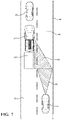
- FIG. 7 illustrates an alternative exemplary host vehicle 470 upon a roadway utilizing data from a confederate vehicle to classify a portion of a destination as clear for a desired lane change, wherein the host vehicle includes a trailer.
- Host vehicle 470 is illustrated upon roadway 40 following behind a slowly-moving second vehicle 20 .
- Host vehicle 470 is illustrated towing trailer 480 .
- Trailer 480 may include a cargo trailer, a boat, a camper unit, or any other similar towable item.
- Trailer 480 may occlude or partially obscure sensors of host vehicle 470 .
- Roadway 40 includes a first lane 42 and a second lane 44 .
- Host vehicle 470 either by designation of a user within host vehicle 470 or through autonomous or semi-autonomous computerized methods operated therein or remotely on behalf of host vehicle 470 , has identified a desired lane change from first lane 42 to second lane 44 .
- a dynamic controller within host vehicle 470 may analyze available data from sensors monitoring second lane 44 to determine whether a portion of the second lane 44 to the right and rear of host vehicle 470 may be classified as clear.
- second lane 44 may be described as the destination lane into which the desired lane change is to occur.
- the dynamic controller may determine 1) a size and geometry of the portion of the destination lane that is to be classified as clear and 2) whether the on-board sensors of the host vehicle are capable of providing data to accomplish classifying the portion of the destination lane as clear.
- the host vehicle may communicate with another vehicle, in the example of FIG. 7 , with confederate vehicle 30 .
- host vehicle 470 may utilize data from sensors of confederate vehicle 30 , in combination with data from on-board sensors of host vehicle 470 , to classify the portion of second lane 44 as clear.
- an exemplary effective perception range 472 of host vehicle 470 is illustrated shortened in comparison to effective perception range 472 of FIG. 1 due to trailer 480 obscuring the sensors of host vehicle 470 in FIG. 7 .
- An exemplary effective perception range 32 of confederate vehicle 30 is additionally illustrated, with effective perception range 472 and effective perception range 32 collectively covering a portion of second lane 44 and generating data useful to classify the portion of second lane 44 as clear.
- FIG. 8 is a flowchart illustrating an exemplary process 500 operable to execute the desired lane change illustrated in FIG. 7 .
- Process 500 starts at step 510 , where at a desired lane change maneuver by a host vehicle 470 into a portion of a destination lane has been identified. Further, at step 510 , a determination has been made that the effective range of sensors of the host vehicle 470 does not fully cover the portion of the destination lane. At step 520 , a determination is made whether the host vehicle 470 's sensors are substantially blocked by a trailer 480 . If the host vehicle 470 's sensors are not blocked by a trailer 480 , the process proceeds to step 560 , where the process ends.
- process 500 is directed specifically to authorizing a lane change in light of a trailer 480 partially obscuring the effective range of the host vehicle 470 's sensors.
- the system may subsequently operate process 200 of FIG. 2 . If a trailer 480 does obscure sensors of the host vehicle 470 , for example, by partially or fully blocking an entirety or a portion of a field of view of the sensors, the process advances to step 530 .
- a determination is made whether a confederate vehicle 30 may be identified as being in position and having threshold effective perception range to gather adequate data regarding the portion of the destination lane.
- step 560 the process ends and the host vehicle 470 does not initiate the lane change maneuver. If a confederate vehicle 30 with threshold effective perception range is identified, the process advances to step 540 .
- step 540 a determination is made whether the portion of the destination lane may be classified as clear. If the portion of the destination lane is not clear, the process advances to step 560 , where the process ends and the host vehicle 470 does not initiate the lane change maneuver. If the portion of the destination lane is clear, the process advances to step 550 .
- step 550 a command is provided authorizing the desired lane change.
- step 560 the process ends.
- Process 500 is exemplary, a number of additional and/or alternative steps are envisioned, and the disclosure is not intended to be limited to the examples provided herein.
- FIG. 9 illustrates an alternative exemplary host vehicle 470 upon a roadway utilizing data from a confederate vehicle to classify a portion of a destination as clear for a desired maneuver, wherein the host vehicle is utilizing an auxiliary control process of dynamic offset to maintain a minimum distance from an oversized vehicle.
- Host vehicle 470 is illustrated upon roadway 600 approaching an oversized vehicle 620 embodied as an oversized load being pulled by a commercial truck 610 .
- Host vehicle 470 is illustrated towing trailer 480 .
- Trailer 480 may occlude or partially obscure sensors of host vehicle 470 .
- Roadway 600 includes a first lane 602 , second lane 604 , and a third lane 606 .
- Host vehicle 470 either by designation of a user within host vehicle 470 or through autonomous or semi-autonomous computerized methods operated therein or remotely on behalf of host vehicle 470 , has identified an offset to be observed in relation to oversized vehicle 620 .
- the offset in relation to oversized vehicle 620 provides a lateral adjustment of host vehicle 470 and trailer 480 , wherein host vehicle 470 moves out of the center of second lane 604 and may move partially into third lane 606 to avoid getting close to oversized vehicle 620 .
- the offset of host vehicle 470 may be described as a lane change maneuver, wherein the destination lane may be identified as third lane 606 .
- While host vehicle 470 may or may not actually enter third lane 606 , the lateral adjustment of host vehicle 470 toward third lane 606 may in some embodiment be authorized when the adjacent portion of third lane 606 is classified as clear.
- a dynamic controller within host vehicle 470 may analyze available data from sensors monitoring third lane 606 to determine whether a portion of the third lane 606 to the right and rear of host vehicle 470 may be classified as clear.
- the dynamic controller through use of programmed code and/or use of reference tables may determine 1) a size and geometry of the portion of the destination lane that is to be classified as clear and 2) whether the on-board sensors of the host vehicle are capable of providing data to accomplish classifying the portion of the destination lane as clear.
- the host vehicle may communicate with another vehicle, in the example of FIG. 9 , with confederate vehicle 30 .
- host vehicle 470 may utilize data from sensors of confederate vehicle 30 , in combination with data from on-board sensors of host vehicle 470 , to classify the portion of third lane 606 as clear.
- an exemplary effective perception range 472 of host vehicle 470 is illustrated shortened in comparison to effective perception range 472 of FIG. 1 due to trailer 480 obscuring the sensors of host vehicle 470 in FIG. 9 .
- An exemplary effective perception range 32 of confederate vehicle 30 is additionally illustrated, with effective perception range 472 and effective perception range 32 collectively covering a portion of third lane 606 and generating data useful to classify the portion of third lane 606 as clear.
- FIG. 10 is a flowchart illustrating an exemplary process 700 operable to execute the desired lane change illustrated in FIG. 9 .
- Process 700 starts at step 710 , where at a desired lane change maneuver by a host vehicle 470 into a portion of a destination lane has been identified. Further, at step 710 , a determination has been made that the effective range of sensors of the host vehicle 470 does not fully cover the portion of the destination lane.
- a determination is made whether an oversized vehicle 620 is detected in front of the host vehicle 470 . If no oversized vehicle 620 is detected, the process proceeds to step 760 , where the process ends. It is noted that process 700 is directed specifically to authorizing a lane change in light of an oversized vehicle 620 being detected.
- the system may subsequently operate process 200 of FIG. 2 . If an oversized vehicle 620 is present, the process advances to step 730 . At step 730 , a determination is made whether the host vehicle 470 's sensors are substantially blocked by a trailer 480 . If the host vehicle 470 's sensors are not blocked by a trailer 480 , the process proceeds to step 760 , where the process ends and the host vehicle 470 does not initiate the lane change maneuver. If a trailer 480 does obscure sensors of the host vehicle, the process advances to step 740 .
- FIG. 11 illustrates an alternative exemplary host vehicle 10 upon a roadway utilizing data from a confederate vehicle 1110 ahead of the host vehicle 10 to classify a portion of a destination as clear for a desired lane change, wherein a third vehicle is situated in a position that partially obscures the on-board sensors of the host vehicle 10 .
- Host vehicle 10 is illustrated upon roadway 40 .
- a nearby vehicle 22 is located rearward of host vehicle 10 .
- Nearby vehicle 22 is situated in a location that partially obscures use of a right rear radar device 170 of host vehicle 10 .
- Roadway 40 includes a first lane 42 and a second lane 44 .
- Host vehicle 10 either by designation of a user within host vehicle 10 or through autonomous or semi-autonomous computerized methods operated therein or remotely on behalf of host vehicle 10 , has identified a desired lane change from second lane 44 to first lane 42 .
- a dynamic controller within host vehicle 10 may analyze available data from sensors monitoring first lane 42 to determine whether a portion of the first lane 42 to the left and rear of host vehicle 10 may be classified as clear.
- first lane 42 may be described as the destination lane into which the desired lane change is to occur.
- the dynamic controller may determine 1) a size and geometry of the portion of the destination lane that is to be classified as clear and 2) whether the on-board sensors of the host vehicle are capable of providing data to accomplish classifying the portion of the destination lane as clear.
- the host vehicle 10 may communicate with another vehicle, in the example of FIG. 11 , with confederate vehicle 1110 . Through the established communication, host vehicle 10 may utilize data from sensors of confederate vehicle 1110 , in combination with data from on-board sensors of host vehicle 10 , to classify the portion of first lane 42 as clear.
- an exemplary effective perception range 16 of host vehicle 10 is illustrated shortened in comparison to effective perception range 12 of FIG. 1 due to nearby vehicle 22 obscuring the sensors of host vehicle 10 in FIG. 11 .
- An exemplary effective perception range 1112 of confederate vehicle 1110 is additionally illustrated, with effective perception range 16 and effective perception range 1112 collectively covering a portion of first lane 42 and generating data useful to classify the portion of first lane 42 as clear.
- FIG. 12 is a flowchart illustrating an exemplary process 800 operable to execute the desired lane change illustrated in FIG. 11 .
- Process 800 starts at step 810 , whereat a desired lane change maneuver by a host vehicle 10 into a portion of a destination lane has been identified.
- process 800 may subsequently operate process 200 of FIG. 2 . If the sensors of the host vehicle 10 are obscured by a nearby vehicle 22 , the process advances to step 830 .
- a determination is made whether a confederate vehicle 1110 may be identified as being in position and having threshold effective perception range to gather adequate data regarding the portion of the destination lane and further whether the portion of the destination lane is clear. If no confederate vehicle 1110 with threshold effective perception range is identified or if the lane is not clear, the process advances to step 860 , where the process ends and the host vehicle 10 does not initiate the lane change maneuver.
- step 840 a determination is made whether the portion of the destination lane is clear. If the portion of the destination lane is not clear, the process advances to step 860 , where the process ends and the host vehicle 10 does not initiate the lane change maneuver. If the portion of the destination lane is clear, the process advances to step 850 . At step 850 , a command is provided authorizing the desired lane change. At step 860 , the process ends.
- Process 800 is exemplary, a number of additional and/or alternative steps are envisioned, and the disclosure is not intended to be limited to the examples provided herein.
- FIG. 13 illustrates an alternative exemplary host vehicle 10 upon a roadway utilizing data from a confederate vehicle 920 to classify a portion of a destination as clear for a desired lane change, wherein a third vehicle 910 is situated in a position that partially obscures the sensors of both the host vehicle and the confederate vehicle.
- Host vehicle 10 is illustrated upon roadway 40 .
- a third vehicle 910 is located rearward of host vehicle 10 .
- An identified confederate vehicle 920 is located reward of third vehicle 910 .
- Third vehicle 910 is situated in a location that partially obscures sensors of both host vehicle 10 and confederate vehicle 920 .
- Roadway 40 includes a first lane 42 and a second lane 44 .
- Host vehicle 10 either by designation of a user within host vehicle 10 or through autonomous or semi-autonomous computerized methods operated therein or remotely on behalf of host vehicle 10 , has identified a desired lane change from second lane 44 to first lane 42 .
- a dynamic controller within host vehicle 10 may analyze available data from sensors monitoring first lane 42 to determine whether a portion of the first lane 42 to the left and rear of host vehicle 10 may be classified as clear.
- first lane 42 may be described as the destination lane into which the desired lane change is to occur.
- the dynamic controller may determine 1) a size and geometry of the portion of the destination lane that is to be classified as clear and 2) whether the on-board sensors of the host vehicle are capable of providing data to accomplish classifying the portion of the destination lane as clear.
- the host vehicle may communicate with another vehicle, in the example of FIG. 11 , with confederate vehicle 920 .
- host vehicle 10 may utilize data from sensors of confederate vehicle 920 , in combination with data from on-board sensors of host vehicle 10 , to classify the portion of first lane 42 as clear.
- an exemplary effective perception range 18 of host vehicle 10 is illustrated as shortened in comparison to effective perception range 12 of FIG. 1 due to nearby vehicle 22 obscuring the sensors of host vehicle 10 in FIG. 13 .
- the exemplary effective perception range 922 of confederate vehicle 920 is illustrated shortened in comparison to effective perception range 32 of confederate vehicle 30 of FIG. 1 .
- Effective perception range 18 and effective perception range 922 collectively cover a portion of first lane 42 and generate data useful to classify the portion of first lane 42 as clear.
- FIG. 14 is a flowchart illustrating an exemplary process 1000 operable to execute the desired lane change illustrated in FIG. 13 .
- Process 1000 starts at step 1010 , where at a desired lane change maneuver by a host vehicle into a portion of a destination lane has been identified.
- step 1020 a determination is made whether sensors of the host vehicle 10 are obscured by a nearby vehicle. If the sensors of the host vehicle are not obscured by a nearby vehicle, the process proceeds to step 1060 , where the process ends and the vehicle does not initiate the lane change maneuver. It is noted that process 1000 is directed specifically to authorizing a lane change in light of a nearby vehicle obscuring a sensor or sensors of the host vehicle 10 .
- the system may subsequently operate process 200 of FIG. 2 . If the sensors of the host vehicle 10 are obscured by a nearby vehicle, the process advances to step 1030 .
- a determination is made whether a confederate vehicle 920 may be identified as being in position and having threshold effective perception range to gather adequate data regarding the portion of the destination lane and further whether the portion of the destination lane is clear. If no confederate vehicle 920 with threshold effective perception range is identified or if the lane is not clear, the process advances to step 1060 , where the process ends and the host vehicle 10 does not initiate the lane change maneuver.
- step 1040 a determination is made whether the portion of the destination lane is clear. If the portion of the destination lane is not clear, the process advances to step 1060 , where the process ends and the host vehicle 10 does not initiate the lane change maneuver. If the portion of the destination lane is clear, the process advances to step 1050 . At step 1050 , a command is provided authorizing the desired lane change. At step 1060 , the process ends.
- Process 1000 is exemplary, a number of additional and/or alternative steps are envisioned, and the disclosure is not intended to be limited to the examples provided herein.
Abstract
Description
D rear =V rv *T lx (1)
T lx=(V tg −V hv)/a hv (2)
wherein Vtg is the target speed of
Claims (18)
Priority Applications (3)
| Application Number | Priority Date | Filing Date | Title |
|---|---|---|---|
| US16/695,897 US11491985B2 (en) | 2019-11-26 | 2019-11-26 | Process and system for sensor sharing for an autonomous lane change |
| DE102020127206.5A DE102020127206A1 (en) | 2019-11-26 | 2020-10-15 | PROCESS AND SYSTEM FOR THE JOINT USE OF SENSORS FOR AUTONOMOUS LANE CHANGE |
| CN202011347166.2A CN112849141A (en) | 2019-11-26 | 2020-11-26 | Process and system for sensor sharing for autonomous lane changes |
Applications Claiming Priority (1)
| Application Number | Priority Date | Filing Date | Title |
|---|---|---|---|
| US16/695,897 US11491985B2 (en) | 2019-11-26 | 2019-11-26 | Process and system for sensor sharing for an autonomous lane change |
Publications (2)
| Publication Number | Publication Date |
|---|---|
| US20210155245A1 US20210155245A1 (en) | 2021-05-27 |
| US11491985B2 true US11491985B2 (en) | 2022-11-08 |
Family
ID=75784323
Family Applications (1)
| Application Number | Title | Priority Date | Filing Date |
|---|---|---|---|
| US16/695,897 Active 2041-01-01 US11491985B2 (en) | 2019-11-26 | 2019-11-26 | Process and system for sensor sharing for an autonomous lane change |
Country Status (3)
| Country | Link |
|---|---|
| US (1) | US11491985B2 (en) |
| CN (1) | CN112849141A (en) |
| DE (1) | DE102020127206A1 (en) |
Families Citing this family (1)
| Publication number | Priority date | Publication date | Assignee | Title |
|---|---|---|---|---|
| US20230095194A1 (en) * | 2021-09-30 | 2023-03-30 | AyDeeKay LLC dba Indie Semiconductor | Dynamic and Selective Pairing Between Proximate Vehicles |
Citations (10)
| Publication number | Priority date | Publication date | Assignee | Title |
|---|---|---|---|---|
| US20130245877A1 (en) * | 2012-03-16 | 2013-09-19 | Google Inc. | Actively Modifying a Field of View of an Autonomous Vehicle in View of Constraints |
| US20160274228A1 (en) * | 2015-03-19 | 2016-09-22 | Delphi Technologies, Inc. | Radar object detection system |
| US20180067496A1 (en) * | 2016-09-06 | 2018-03-08 | Delphi Technologies, Inc. | Automated vehicle lane change control system |
| US20180079420A1 (en) * | 2016-09-21 | 2018-03-22 | Apple Inc. | Vehicle Control System |
| US20180268703A1 (en) * | 2017-03-17 | 2018-09-20 | Denso International America, Inc. | Vehicle system and vehicle controller for controlling vehicle |
| US20200108869A1 (en) * | 2018-10-08 | 2020-04-09 | Mando Corporation | Apparatus and method for controlling lane change using vehicle-to-vehicle communication information and apparatus for calculating tendency information for same |
| US20200186290A1 (en) * | 2018-12-11 | 2020-06-11 | Apple Inc. | Groupcast Transmission with Feedback for Intra-Platooning and Inter-Platooning Communications |
| US20200367096A1 (en) * | 2018-02-09 | 2020-11-19 | Lg Electronics Inc. | V2x communication device and v2x communication method of v2x communication device |
| US20210009133A1 (en) * | 2019-07-08 | 2021-01-14 | Toyota Motor Engineering & Manufacturing North America, Inc. | Fleet-based average lane change and driver-specific behavior modelling for autonomous vehicle lane change operation |
| WO2021053474A1 (en) * | 2019-09-17 | 2021-03-25 | Kpit Technologies Limited | System and method for dynamic evasive maneuver trajectory planning of a host vehicle |
Family Cites Families (1)
| Publication number | Priority date | Publication date | Assignee | Title |
|---|---|---|---|---|
| US9187117B2 (en) * | 2012-01-17 | 2015-11-17 | Ford Global Technologies, Llc | Autonomous lane control system |
-
2019
- 2019-11-26 US US16/695,897 patent/US11491985B2/en active Active
-
2020
- 2020-10-15 DE DE102020127206.5A patent/DE102020127206A1/en active Pending
- 2020-11-26 CN CN202011347166.2A patent/CN112849141A/en active Pending
Patent Citations (10)
| Publication number | Priority date | Publication date | Assignee | Title |
|---|---|---|---|---|
| US20130245877A1 (en) * | 2012-03-16 | 2013-09-19 | Google Inc. | Actively Modifying a Field of View of an Autonomous Vehicle in View of Constraints |
| US20160274228A1 (en) * | 2015-03-19 | 2016-09-22 | Delphi Technologies, Inc. | Radar object detection system |
| US20180067496A1 (en) * | 2016-09-06 | 2018-03-08 | Delphi Technologies, Inc. | Automated vehicle lane change control system |
| US20180079420A1 (en) * | 2016-09-21 | 2018-03-22 | Apple Inc. | Vehicle Control System |
| US20180268703A1 (en) * | 2017-03-17 | 2018-09-20 | Denso International America, Inc. | Vehicle system and vehicle controller for controlling vehicle |
| US20200367096A1 (en) * | 2018-02-09 | 2020-11-19 | Lg Electronics Inc. | V2x communication device and v2x communication method of v2x communication device |
| US20200108869A1 (en) * | 2018-10-08 | 2020-04-09 | Mando Corporation | Apparatus and method for controlling lane change using vehicle-to-vehicle communication information and apparatus for calculating tendency information for same |
| US20200186290A1 (en) * | 2018-12-11 | 2020-06-11 | Apple Inc. | Groupcast Transmission with Feedback for Intra-Platooning and Inter-Platooning Communications |
| US20210009133A1 (en) * | 2019-07-08 | 2021-01-14 | Toyota Motor Engineering & Manufacturing North America, Inc. | Fleet-based average lane change and driver-specific behavior modelling for autonomous vehicle lane change operation |
| WO2021053474A1 (en) * | 2019-09-17 | 2021-03-25 | Kpit Technologies Limited | System and method for dynamic evasive maneuver trajectory planning of a host vehicle |
Also Published As
| Publication number | Publication date |
|---|---|
| DE102020127206A1 (en) | 2021-05-27 |
| CN112849141A (en) | 2021-05-28 |
| US20210155245A1 (en) | 2021-05-27 |
Similar Documents
| Publication | Publication Date | Title |
|---|---|---|
| US10331135B2 (en) | Systems and methods for maneuvering around obstacles in autonomous vehicles | |
| US10583839B2 (en) | Method of lane change decision-making and path planning | |
| US11584388B2 (en) | Driving control method and driving control apparatus | |
| US11458963B2 (en) | Driving control method and driving control apparatus | |
| CN110053617B (en) | Vehicle control device, vehicle control method, and storage medium | |
| CN107709122B (en) | Prospective control system for motor vehicle | |
| JP2021089732A (en) | System and method for providing alarm to surrounding vehicles in order to avoid collision | |
| US20190276029A1 (en) | Vehicle control device, vehicle control method, and storage medium | |
| EP3782000A1 (en) | A method for controlling a string of vehicles | |
| CN108340918A (en) | Lane changing | |
| US11127301B1 (en) | Systems and methods for adapting operation of an assistance system according to the presence of a trailer | |
| JP2019159428A (en) | Vehicle control device, vehicle control method and program | |
| US10866103B2 (en) | Vehicle perception-data gathering system and method | |
| JP2019131077A (en) | Vehicle control device, vehicle control method, and program | |
| US11260789B2 (en) | Out-of-vehicle notification device | |
| KR20210095757A (en) | Vehicle for performing autonomous driving using a plurality of sensors and operating method thereof | |
| CN109955851B (en) | Lane changing decision and track planning method | |
| CN113228131B (en) | Method and system for providing ambient data | |
| US11491985B2 (en) | Process and system for sensor sharing for an autonomous lane change | |
| US20210179105A1 (en) | Vehicle and method of controlling the same | |
| CN110194153B (en) | Vehicle control device, vehicle control method, and storage medium | |
| CN114084132A (en) | Control method and device and terminal equipment | |
| US20220203985A1 (en) | Vehicle control device, vehicle control method, and storage medium | |
| US11827223B2 (en) | Systems and methods for intersection maneuvering by vehicles | |
| US20240067174A1 (en) | Vehicle systems and methods to longitudinally adjust lane positioning |
Legal Events
| Date | Code | Title | Description |
|---|---|---|---|
| AS | Assignment |
Owner name: GM GLOBAL TECHNOLOGY OPERATIONS LLC, MICHIGAN Free format text: ASSIGNMENT OF ASSIGNORS INTEREST;ASSIGNORS:NASERIAN, MOHAMMAD;HAY, CURTIS L.;JAFARI TAFTI, SAYYED ROUHOLLAH;AND OTHERS;REEL/FRAME:051122/0126 Effective date: 20191125 |
|
| FEPP | Fee payment procedure |
Free format text: ENTITY STATUS SET TO UNDISCOUNTED (ORIGINAL EVENT CODE: BIG.); ENTITY STATUS OF PATENT OWNER: LARGE ENTITY |
|
| STPP | Information on status: patent application and granting procedure in general |
Free format text: DOCKETED NEW CASE - READY FOR EXAMINATION |
|
| STPP | Information on status: patent application and granting procedure in general |
Free format text: NON FINAL ACTION MAILED |
|
| STPP | Information on status: patent application and granting procedure in general |
Free format text: RESPONSE TO NON-FINAL OFFICE ACTION ENTERED AND FORWARDED TO EXAMINER |
|
| STPP | Information on status: patent application and granting procedure in general |
Free format text: NOTICE OF ALLOWANCE MAILED -- APPLICATION RECEIVED IN OFFICE OF PUBLICATIONS |
|
| STPP | Information on status: patent application and granting procedure in general |
Free format text: PUBLICATIONS -- ISSUE FEE PAYMENT RECEIVED |
|
| STPP | Information on status: patent application and granting procedure in general |
Free format text: PUBLICATIONS -- ISSUE FEE PAYMENT VERIFIED |
|
| STCF | Information on status: patent grant |
Free format text: PATENTED CASE |