JP6930600B2 - Vehicle position estimation device and vehicle control device - Google Patents
Vehicle position estimation device and vehicle control device Download PDFInfo
- Publication number
- JP6930600B2 JP6930600B2 JP2019554434A JP2019554434A JP6930600B2 JP 6930600 B2 JP6930600 B2 JP 6930600B2 JP 2019554434 A JP2019554434 A JP 2019554434A JP 2019554434 A JP2019554434 A JP 2019554434A JP 6930600 B2 JP6930600 B2 JP 6930600B2
- Authority
- JP
- Japan
- Prior art keywords
- vehicle
- data
- road
- marking
- parking lot
- Prior art date
- Legal status (The legal status is an assumption and is not a legal conclusion. Google has not performed a legal analysis and makes no representation as to the accuracy of the status listed.)
- Active
Links
- 239000003550 marker Substances 0.000 claims description 75
- 238000012937 correction Methods 0.000 claims description 30
- 230000008859 change Effects 0.000 claims description 28
- 238000000034 method Methods 0.000 description 48
- 238000012545 processing Methods 0.000 description 46
- 238000004891 communication Methods 0.000 description 43
- 238000010586 diagram Methods 0.000 description 39
- 238000004364 calculation method Methods 0.000 description 24
- 230000001133 acceleration Effects 0.000 description 22
- 230000008569 process Effects 0.000 description 22
- 238000003384 imaging method Methods 0.000 description 13
- 230000009466 transformation Effects 0.000 description 12
- 230000006870 function Effects 0.000 description 10
- 238000012384 transportation and delivery Methods 0.000 description 8
- 230000005540 biological transmission Effects 0.000 description 6
- 238000001514 detection method Methods 0.000 description 6
- 230000001186 cumulative effect Effects 0.000 description 5
- 238000013523 data management Methods 0.000 description 5
- 230000004044 response Effects 0.000 description 5
- 238000006243 chemical reaction Methods 0.000 description 4
- 239000000284 extract Substances 0.000 description 4
- 238000004590 computer program Methods 0.000 description 2
- 230000000694 effects Effects 0.000 description 2
- 239000004973 liquid crystal related substance Substances 0.000 description 2
- 238000012544 monitoring process Methods 0.000 description 2
- 238000012546 transfer Methods 0.000 description 2
- 230000009286 beneficial effect Effects 0.000 description 1
- 238000005516 engineering process Methods 0.000 description 1
- 238000000605 extraction Methods 0.000 description 1
- 230000006872 improvement Effects 0.000 description 1
- 230000010365 information processing Effects 0.000 description 1
- 238000009434 installation Methods 0.000 description 1
- 238000012986 modification Methods 0.000 description 1
- 230000004048 modification Effects 0.000 description 1
- 238000012806 monitoring device Methods 0.000 description 1
- 239000007787 solid Substances 0.000 description 1
- 238000013519 translation Methods 0.000 description 1
Images


Classifications
-
- G—PHYSICS
- G01—MEASURING; TESTING
- G01C—MEASURING DISTANCES, LEVELS OR BEARINGS; SURVEYING; NAVIGATION; GYROSCOPIC INSTRUMENTS; PHOTOGRAMMETRY OR VIDEOGRAMMETRY
- G01C21/00—Navigation; Navigational instruments not provided for in groups G01C1/00 - G01C19/00
- G01C21/26—Navigation; Navigational instruments not provided for in groups G01C1/00 - G01C19/00 specially adapted for navigation in a road network
- G01C21/28—Navigation; Navigational instruments not provided for in groups G01C1/00 - G01C19/00 specially adapted for navigation in a road network with correlation of data from several navigational instruments
- G01C21/30—Map- or contour-matching
-
- B—PERFORMING OPERATIONS; TRANSPORTING
- B62—LAND VEHICLES FOR TRAVELLING OTHERWISE THAN ON RAILS
- B62D—MOTOR VEHICLES; TRAILERS
- B62D15/00—Steering not otherwise provided for
- B62D15/02—Steering position indicators ; Steering position determination; Steering aids
- B62D15/027—Parking aids, e.g. instruction means
- B62D15/0285—Parking performed automatically
-
- G—PHYSICS
- G01—MEASURING; TESTING
- G01C—MEASURING DISTANCES, LEVELS OR BEARINGS; SURVEYING; NAVIGATION; GYROSCOPIC INSTRUMENTS; PHOTOGRAMMETRY OR VIDEOGRAMMETRY
- G01C21/00—Navigation; Navigational instruments not provided for in groups G01C1/00 - G01C19/00
- G01C21/10—Navigation; Navigational instruments not provided for in groups G01C1/00 - G01C19/00 by using measurements of speed or acceleration
- G01C21/12—Navigation; Navigational instruments not provided for in groups G01C1/00 - G01C19/00 by using measurements of speed or acceleration executed aboard the object being navigated; Dead reckoning
- G01C21/16—Navigation; Navigational instruments not provided for in groups G01C1/00 - G01C19/00 by using measurements of speed or acceleration executed aboard the object being navigated; Dead reckoning by integrating acceleration or speed, i.e. inertial navigation
- G01C21/165—Navigation; Navigational instruments not provided for in groups G01C1/00 - G01C19/00 by using measurements of speed or acceleration executed aboard the object being navigated; Dead reckoning by integrating acceleration or speed, i.e. inertial navigation combined with non-inertial navigation instruments
- G01C21/1656—Navigation; Navigational instruments not provided for in groups G01C1/00 - G01C19/00 by using measurements of speed or acceleration executed aboard the object being navigated; Dead reckoning by integrating acceleration or speed, i.e. inertial navigation combined with non-inertial navigation instruments with passive imaging devices, e.g. cameras
-
- G—PHYSICS
- G01—MEASURING; TESTING
- G01C—MEASURING DISTANCES, LEVELS OR BEARINGS; SURVEYING; NAVIGATION; GYROSCOPIC INSTRUMENTS; PHOTOGRAMMETRY OR VIDEOGRAMMETRY
- G01C21/00—Navigation; Navigational instruments not provided for in groups G01C1/00 - G01C19/00
- G01C21/26—Navigation; Navigational instruments not provided for in groups G01C1/00 - G01C19/00 specially adapted for navigation in a road network
- G01C21/34—Route searching; Route guidance
- G01C21/36—Input/output arrangements for on-board computers
- G01C21/3602—Input other than that of destination using image analysis, e.g. detection of road signs, lanes, buildings, real preceding vehicles using a camera
-
- G—PHYSICS
- G01—MEASURING; TESTING
- G01C—MEASURING DISTANCES, LEVELS OR BEARINGS; SURVEYING; NAVIGATION; GYROSCOPIC INSTRUMENTS; PHOTOGRAMMETRY OR VIDEOGRAMMETRY
- G01C21/00—Navigation; Navigational instruments not provided for in groups G01C1/00 - G01C19/00
- G01C21/26—Navigation; Navigational instruments not provided for in groups G01C1/00 - G01C19/00 specially adapted for navigation in a road network
- G01C21/34—Route searching; Route guidance
- G01C21/36—Input/output arrangements for on-board computers
- G01C21/3679—Retrieval, searching and output of POI information, e.g. hotels, restaurants, shops, filling stations, parking facilities
- G01C21/3685—Retrieval, searching and output of POI information, e.g. hotels, restaurants, shops, filling stations, parking facilities the POI's being parking facilities
-
- G—PHYSICS
- G06—COMPUTING; CALCULATING OR COUNTING
- G06V—IMAGE OR VIDEO RECOGNITION OR UNDERSTANDING
- G06V10/00—Arrangements for image or video recognition or understanding
- G06V10/40—Extraction of image or video features
- G06V10/48—Extraction of image or video features by mapping characteristic values of the pattern into a parameter space, e.g. Hough transformation
-
- G—PHYSICS
- G06—COMPUTING; CALCULATING OR COUNTING
- G06V—IMAGE OR VIDEO RECOGNITION OR UNDERSTANDING
- G06V20/00—Scenes; Scene-specific elements
- G06V20/50—Context or environment of the image
- G06V20/56—Context or environment of the image exterior to a vehicle by using sensors mounted on the vehicle
- G06V20/58—Recognition of moving objects or obstacles, e.g. vehicles or pedestrians; Recognition of traffic objects, e.g. traffic signs, traffic lights or roads
- G06V20/586—Recognition of moving objects or obstacles, e.g. vehicles or pedestrians; Recognition of traffic objects, e.g. traffic signs, traffic lights or roads of parking space
-
- G—PHYSICS
- G06—COMPUTING; CALCULATING OR COUNTING
- G06V—IMAGE OR VIDEO RECOGNITION OR UNDERSTANDING
- G06V20/00—Scenes; Scene-specific elements
- G06V20/50—Context or environment of the image
- G06V20/56—Context or environment of the image exterior to a vehicle by using sensors mounted on the vehicle
- G06V20/588—Recognition of the road, e.g. of lane markings; Recognition of the vehicle driving pattern in relation to the road
-
- G—PHYSICS
- G08—SIGNALLING
- G08G—TRAFFIC CONTROL SYSTEMS
- G08G1/00—Traffic control systems for road vehicles
- G08G1/09—Arrangements for giving variable traffic instructions
- G08G1/0962—Arrangements for giving variable traffic instructions having an indicator mounted inside the vehicle, e.g. giving voice messages
- G08G1/0968—Systems involving transmission of navigation instructions to the vehicle
- G08G1/096805—Systems involving transmission of navigation instructions to the vehicle where the transmitted instructions are used to compute a route
- G08G1/096827—Systems involving transmission of navigation instructions to the vehicle where the transmitted instructions are used to compute a route where the route is computed onboard
-
- G—PHYSICS
- G08—SIGNALLING
- G08G—TRAFFIC CONTROL SYSTEMS
- G08G1/00—Traffic control systems for road vehicles
- G08G1/09—Arrangements for giving variable traffic instructions
- G08G1/0962—Arrangements for giving variable traffic instructions having an indicator mounted inside the vehicle, e.g. giving voice messages
- G08G1/0968—Systems involving transmission of navigation instructions to the vehicle
- G08G1/096833—Systems involving transmission of navigation instructions to the vehicle where different aspects are considered when computing the route
- G08G1/09685—Systems involving transmission of navigation instructions to the vehicle where different aspects are considered when computing the route where the complete route is computed only once and not updated
-
- G—PHYSICS
- G08—SIGNALLING
- G08G—TRAFFIC CONTROL SYSTEMS
- G08G1/00—Traffic control systems for road vehicles
- G08G1/14—Traffic control systems for road vehicles indicating individual free spaces in parking areas
- G08G1/141—Traffic control systems for road vehicles indicating individual free spaces in parking areas with means giving the indication of available parking spaces
- G08G1/143—Traffic control systems for road vehicles indicating individual free spaces in parking areas with means giving the indication of available parking spaces inside the vehicles
-
- G—PHYSICS
- G08—SIGNALLING
- G08G—TRAFFIC CONTROL SYSTEMS
- G08G1/00—Traffic control systems for road vehicles
- G08G1/14—Traffic control systems for road vehicles indicating individual free spaces in parking areas
- G08G1/145—Traffic control systems for road vehicles indicating individual free spaces in parking areas where the indication depends on the parking areas
- G08G1/146—Traffic control systems for road vehicles indicating individual free spaces in parking areas where the indication depends on the parking areas where the parking area is a limited parking space, e.g. parking garage, restricted space
Landscapes
- Engineering & Computer Science (AREA)
- Radar, Positioning & Navigation (AREA)
- Remote Sensing (AREA)
- Physics & Mathematics (AREA)
- General Physics & Mathematics (AREA)
- Automation & Control Theory (AREA)
- Multimedia (AREA)
- Theoretical Computer Science (AREA)
- Chemical & Material Sciences (AREA)
- Combustion & Propulsion (AREA)
- Transportation (AREA)
- Mechanical Engineering (AREA)
- Mathematical Physics (AREA)
- Computer Vision & Pattern Recognition (AREA)
- Traffic Control Systems (AREA)
- Control Of Driving Devices And Active Controlling Of Vehicle (AREA)
- Navigation (AREA)
Description
本発明の実施形態は、車両位置推定装置および車両制御装置に関する。 Embodiments of the present invention relate to a vehicle position estimation device and a vehicle control device.
近年、駐車場内の所定の降車領域で車両から乗員が降車した後、所定の指示に応じて車両が降車領域から空きの駐車領域へ自動で移動して駐車する自動駐車と、当該自動駐車が完了した後、所定の呼び出しに応じて車両が駐車領域から出庫して所定の乗車領域へ自動で移動して停車する自動出庫と、を含む自動バレー駐車を実現するための技術が検討されている。 In recent years, after an occupant disembarks from a vehicle in a predetermined disembarkation area in a parking lot, the vehicle automatically moves from the disembarkation area to an empty parking area according to a predetermined instruction and parks, and the automatic parking is completed. After that, a technique for realizing automatic valet parking including automatic warehousing in which the vehicle leaves the parking area in response to a predetermined call, automatically moves to a predetermined boarding area and stops, is being studied.
上記のような自動バレー駐車などといった、自動走行が前提となる技術においては、自動走行中における車両の現在位置を正確に把握することが重要となる。この点に関して、従来から、車輪速センサなどの検出値を用いて車両の現在位置を推定する手法(いわゆるオドメトリ)が知られている。しかしながら、この手法においては、車両の移動距離が大きくなる程、推定結果の誤差が累積されて大きくなっていくため、車両の現在位置を正確に把握することができない場合がある。 In technologies that require automatic driving, such as automatic valley parking as described above, it is important to accurately grasp the current position of the vehicle during automatic driving. In this regard, a method (so-called odometry) for estimating the current position of a vehicle using a detected value such as a wheel speed sensor has been conventionally known. However, in this method, as the moving distance of the vehicle increases, the error of the estimation result is accumulated and becomes large, so that it may not be possible to accurately grasp the current position of the vehicle.
そこで、実施形態の課題の一つは、車両の現在位置を正確に把握することが可能な車両位置推定装置および車両制御装置を提供することである。 Therefore, one of the problems of the embodiment is to provide a vehicle position estimation device and a vehicle control device capable of accurately grasping the current position of the vehicle.
実施形態の一例としての車両位置推定装置は、駐車場の路面に設置された路面標示の絶対方位および絶対位置を特定可能な駐車場データを取得する駐車場データ取得部と、車両の周辺の状況を撮像する車載カメラによって得られる画像データを取得する画像データ取得部と、画像データから路面標示に関する路面標示データを検出することで、画像データ上における車両に対する路面標示の相対方位および相対位置を算出し、算出した相対方位および相対位置と、駐車場データと、に基づいて、車両の実方位および実位置を推定する位置推定部と、を備える。 The vehicle position estimation device as an example of the embodiment includes a parking lot data acquisition unit that acquires parking lot data capable of specifying the absolute orientation and absolute position of the road surface marking installed on the road surface of the parking lot, and a situation around the vehicle. By detecting the road surface marking data related to the road surface marking from the image data and the image data acquisition unit that acquires the image data obtained by the in-vehicle camera that captures the image, the relative orientation and the relative position of the road surface marking with respect to the vehicle on the image data are calculated. It is provided with a position estimation unit that estimates the actual orientation and actual position of the vehicle based on the calculated relative orientation and relative position, the parking lot data, and the parking lot data.
上記の車両位置推定装置によれば、画像データに基づいて算出される相対位置および相対方位を利用して特定される計算上の路面標示の位置および方位と、駐車場データに基づいて特定される路面標示の(正規の)絶対位置および絶対方位と、のずれを考慮して、車両の現在位置(実位置)および現在の向き(実方位)を正確に把握することができる。 According to the above-mentioned vehicle position estimation device, it is specified based on the position and direction of the calculated road marking specified by using the relative position and the relative direction calculated based on the image data, and the parking lot data. The current position (actual position) and current orientation (actual direction) of the vehicle can be accurately grasped in consideration of the deviation between the (regular) absolute position and the absolute direction of the road marking.
上述した一例としての車両位置推定装置において、位置推定部は、車両の左側方および右側方のうち一方の状況を表す画像データであるサイド画像データから路面標示データを検出することで、車両の左側方および右側方のうち一方に存在する路面標示の相対方位および相対位置を算出する。この構成によれば、路面標示が写り込みやすいサイド画像データを利用して、路面標示の相対方位および相対位置を容易に算出することができる。 In the vehicle position estimation device as an example described above, the position estimation unit detects the road marking data from the side image data which is the image data representing the situation of one of the left side and the right side of the vehicle, thereby detecting the left side of the vehicle. Calculate the relative orientation and relative position of the road markings that exist on either the side or the right side. According to this configuration, the relative direction and the relative position of the road marking can be easily calculated by using the side image data in which the road marking is easily reflected.
また、上述した一例としての車両位置推定装置において、駐車場データ取得部は、駐車場データとして、駐車場内に予め設けられた駐車領域の境界を示す路面標示である区画線の絶対方位および絶対位置を特定可能な区画線データを取得し、位置推定部は、画像データ上における区画線の端部の位置と当該区画線の向きとを路面標示データとして検出することで、区画線の相対方位および相対位置を算出し、算出した相対方位および相対位置と、区画線データと、に基づいて、車両の実方位および実位置を推定する。この構成によれば、駐車領域の境界を示す路面標示として一般的に設けられている区画線を利用して、車両の実方位および実位置を容易に推定することができる。 Further, in the vehicle position estimation device as an example described above, the parking lot data acquisition unit uses the parking lot data as the absolute direction and the absolute position of the lane marking which is a road surface marking indicating the boundary of the parking area provided in the parking lot in advance. By acquiring the lane marking data that can specify The relative position is calculated, and the actual orientation and actual position of the vehicle are estimated based on the calculated relative orientation and relative position and the lane marking data. According to this configuration, the actual orientation and the actual position of the vehicle can be easily estimated by using the lane markings generally provided as road markings indicating the boundaries of the parking area.
区画線を利用する上述した構成において、位置推定部は、画像データ上における区画線のうち、当該区画線によって開口部を持って区画された駐車領域の開口部側の端部の位置と、当該端部を含んだ区画線の延びる方向とを、路面標示データとして検出する。この構成によれば、区画線のうち駐車領域の開口部側の端部の位置と当該端部を含んだ区画線の延びる方向とを利用して、車両の実方位および実位置を容易に推定することができる。 In the above-described configuration using the lane marking, the position estimation unit includes the position of the end portion of the lane marking on the image data on the opening side of the parking area partitioned by the lane marking with the opening. The direction in which the lane marking including the end is extended is detected as road marking data. According to this configuration, the actual orientation and the actual position of the vehicle can be easily estimated by using the position of the end portion of the parking area on the opening side of the lane marking and the extending direction of the lane marking including the end portion. can do.
また、区画線を利用する上述した構成において、位置推定部は、画像データ上における区画線の端部の中心点の位置と、当該端部を含んだ区画線の延びる方向とを、路面標示データとして検出する。この構成によれば、区画線の端部の中心点の位置と当該端部を含んだ区画線の延びる方向とを利用して、車両の実方位および実位置を容易に推定することができる。 Further, in the above-described configuration using the lane marking, the position estimation unit indicates the position of the center point of the end of the lane marking on the image data and the extending direction of the lane marking including the end as road marking data. Detect as. According to this configuration, the actual orientation and the actual position of the vehicle can be easily estimated by using the position of the center point of the end portion of the lane marking and the extending direction of the lane marking including the end portion.
また、上述した一例としての車両位置推定装置において、駐車場データ取得部は、駐車場データとして、駐車場内における車両の走行経路の周辺に予め設けられた路面標示である、第1線分を含む第1マーカの絶対方位および絶対位置を特定可能な第1マーカデータを取得し、位置推定部は、画像データ上における第1マーカの位置と当該第1マーカに含まれる第1線分の向きとを路面標示データとして検出することで、車両に対する第1マーカの相対方位および相対位置を算出し、算出した相対方位および相対位置と、第1マーカデータと、に基づいて、車両の実方位および実位置を推定する。この構成によれば、第1マーカを利用して、車両の実方位および実位置を容易に推定することができる。 Further, in the vehicle position estimation device as an example described above, the parking lot data acquisition unit includes, as parking lot data, a first line portion which is a road marking provided in advance around the traveling route of the vehicle in the parking lot. The first marker data that can specify the absolute orientation and the absolute position of the first marker is acquired, and the position estimation unit determines the position of the first marker on the image data and the direction of the first line segment included in the first marker. Is calculated as the relative orientation and relative position of the first marker with respect to the vehicle by detecting as road marking data, and the actual orientation and actual position of the vehicle are calculated based on the calculated relative orientation and relative position and the first marker data. Estimate the position. According to this configuration, the actual direction and the actual position of the vehicle can be easily estimated by using the first marker.
また、上述した一例としての車両位置推定装置において、駐車場データ取得部は、駐車場データとして、駐車場内に予め設けられた駐車領域の境界を示す路面標示である区画線の絶対方位および絶対位置を特定可能な区画線データと、区画線の周辺の領域であって、駐車場内における車両の旋回経路の内側の領域に設けられる路面標示である、第2線分を含む第2マーカの絶対方位および絶対位置を特定可能な第2マーカデータと、の少なくとも一方を取得し、位置推定部は、車両の旋回時に、車両の旋回の内側の状況を表す画像データである内側画像データから区画線および第2マーカの少なくとも一方に関するデータを路面標示データとして検出することで、車両の旋回の内側に存在する区画線および第2マーカの少なくとも一方の相対方位および相対位置を算出し、算出した相対方位および相対位置と、検出した路面標示データに対応する区画線データおよび第2マーカデータの少なくとも一方と、に基づいて、車両の実方位および実位置を推定する。この構成によれば、区画線と第2マーカとの少なくとも一方を利用して、旋回時における車両の実方位および実位置を精度良く推定することができる。 Further, in the vehicle position estimation device as an example described above, the parking lot data acquisition unit uses the parking lot data as the absolute orientation and the absolute position of the lane marking which is a road surface marking indicating the boundary of the parking area provided in the parking lot in advance. The absolute orientation of the second marker including the second line segment, which is the area around the lane marking and is the road surface marking provided in the area inside the turning path of the vehicle in the parking lot. At least one of the second marker data and the second marker data capable of specifying the absolute position are acquired, and the position estimation unit obtains a lane marking and a lane marking from the inner image data which is image data showing the situation inside the turning of the vehicle when the vehicle turns. By detecting the data relating to at least one of the second markers as road surface marking data, the relative orientation and the relative position of at least one of the lane marking and the second marker existing inside the turn of the vehicle are calculated, and the calculated relative orientation and the relative orientation and the relative position are calculated. The actual orientation and actual position of the vehicle are estimated based on the relative position and at least one of the lane marking data and the second marker data corresponding to the detected road surface marking data. According to this configuration, the actual direction and the actual position of the vehicle at the time of turning can be accurately estimated by using at least one of the lane marking and the second marker.
また、上述した一例としての車両位置推定装置において、位置推定部は、画像データ上の第1座標系における路面標示の方位および位置を示す第1の値を路面標示データとして検出し、当該第1の値を車載カメラに対応した第2座標系における第2の値に変換し、当該第2の値を車両に対応した第3座標系における第3の値に変換することで、当該第3の値を、車両に対する路面標示の相対方位および相対位置として算出する。この構成によれば、座標変換により、車両に対する路面標示の相対方位および相対位置を容易に算出することができる。 Further, in the vehicle position estimation device as an example described above, the position estimation unit detects the first value indicating the direction and position of the road marking in the first coordinate system on the image data as the road marking data, and the first value thereof. Is converted to the second value in the second coordinate system corresponding to the in-vehicle camera, and the second value is converted to the third value in the third coordinate system corresponding to the vehicle. The values are calculated as the relative orientation and position of the road markings with respect to the vehicle. According to this configuration, the relative direction and the relative position of the road marking with respect to the vehicle can be easily calculated by the coordinate transformation.
また、上述した一例としての車両位置推定装置において、位置推定部は、車両の実方位および実位置の前回の推定結果と、オドメトリに基づく車両の実方位および実位置の変化量と、に基づく車両の実方位および実位置の推定値と、路面標示の相対方位および相対位置と、に基づいて、路面標示の計算上の絶対方位および絶対位置を算出し、当該計算上の絶対位置の周辺に対応した部分データを駐車場データから抽出し、計算上の絶対位置と、部分データに基づく絶対方位および絶対位置と、の差分に基づいて、車両の実方位および実位置の推定値を補正し、補正結果に基づいて、車両の実方位および実位置を推定する。この構成によれば、駐車場データの全てを利用することなく、部分データを利用して、車両の実方位および実位置を容易に推定することができる。 Further, in the vehicle position estimation device as an example described above, the position estimation unit uses the vehicle based on the previous estimation result of the actual direction and the actual position of the vehicle and the amount of change in the actual direction and the actual position of the vehicle based on the odometry. Based on the estimated values of the actual direction and actual position of the road surface marking and the relative orientation and relative position of the road surface marking, the calculated absolute orientation and absolute position of the road surface marking are calculated, and the periphery of the calculated absolute position is supported. The partial data is extracted from the parking lot data, and the estimated values of the actual orientation and actual position of the vehicle are corrected and corrected based on the difference between the calculated absolute position and the absolute orientation and absolute position based on the partial data. Based on the results, the actual orientation and position of the vehicle are estimated. According to this configuration, the actual orientation and the actual position of the vehicle can be easily estimated by using the partial data without using all the parking lot data.
この場合において、位置推定部は、計算上の絶対方位と部分データに基づく絶対方位とが一致するように実方位の推定値を補正した後に、計算上の絶対位置と部分データに基づく絶対位置とが一致するように実位置の推定値を補正する。この構成によれば、車両の実方位および実位置の推定値を段階的に容易に補正することができる。 In this case, the position estimation unit corrects the estimated value of the actual direction so that the calculated absolute direction and the absolute direction based on the partial data match, and then sets the calculated absolute position and the absolute position based on the partial data. Correct the estimated value of the actual position so that According to this configuration, the estimated values of the actual orientation and the actual position of the vehicle can be easily corrected step by step.
実施形態の他の一例としての車両位置推定装置は、駐車場の路面に設置された複数の路面標示のそれぞれの絶対位置に関する情報を含む駐車場データを取得する駐車場データ取得部と、車両の周辺の状況を撮像する車載カメラによって得られる撮像画像の画像データを取得する画像データ取得部と、画像データから複数の路面標示のうち少なくとも2つの路面標示に関する路面標示データを検出することで、画像データ上における車両に対する少なくとも2つの路面標示の相対位置を算出し、算出した相対位置と、駐車場データと、に基づいて、車両の実位置を推定する位置推定部と、を備える。 A vehicle position estimation device as another example of the embodiment includes a parking lot data acquisition unit that acquires parking lot data including information on the absolute position of each of a plurality of road markings installed on the road surface of the parking lot, and a vehicle. An image is obtained by detecting an image data acquisition unit that acquires image data of an captured image obtained by an in-vehicle camera that captures the surrounding situation, and road marking data related to at least two road markings out of a plurality of road markings from the image data. It is provided with a position estimation unit that calculates the relative positions of at least two road markings on the data with respect to the vehicle, and estimates the actual position of the vehicle based on the calculated relative positions and the parking lot data.
上記の車両位置推定装置によれば、画像データに基づいて算出される相対位置を利用して特定される少なくとも2つの路面標示の計算上の路面標示の位置(およびそれらの位置関係)と、駐車場データに基づいて特定される当該少なくとも2つの路面標示の(正規の)絶対位置(およびそれらの位置関係)と、のずれを考慮して、車両の現在位置(実位置)を正確に把握することができる。 According to the above-mentioned vehicle position estimation device, the positions (and their positional relationships) of at least two road markings specified by using the relative positions calculated based on the image data and the positions of the road markings and their positions are stationed. Accurately grasp the current position (actual position) of the vehicle in consideration of the deviation from the (regular) absolute position (and their positional relationship) of the at least two road markings specified based on the yard data. be able to.
上述した他の一例としての車両位置推定装置において、位置推定部は、車両の左側方の状況を表す画像データである左サイド画像データから、複数の路面標示のうち車両の左側方に存在する少なくとも1つの第1路面標示の第1位置を路面標示データとして検出するとともに、車両の右側方の状況を表す画像データである右サイド画像データから、複数の路面標示のうち車両の右側方に存在する少なくとも1つの第2路面標示の第2位置を路面標示データとして検出することで、第1路面標示および第2路面標示の相対位置を算出する。この構成によれば、異なる2種類の画像(左サイド画像データおよび右サイド画像データ)を利用して、少なくとも2つの路面標示の相対位置を精度良く算出することができる。 In the vehicle position estimation device as another example described above, the position estimation unit is present at least on the left side of the vehicle among a plurality of road markings from the left side image data which is image data representing the situation on the left side of the vehicle. The first position of one first road marking is detected as road marking data, and from the right side image data which is image data showing the situation on the right side of the vehicle, it exists on the right side of the vehicle among a plurality of road markings. By detecting the second position of at least one second road marking as road marking data, the relative positions of the first road marking and the second road marking are calculated. According to this configuration, it is possible to accurately calculate the relative positions of at least two road markings by using two different types of images (left side image data and right side image data).
また、上述した他の一例としての車両位置推定装置において、位置推定部は、車両の左側方および右側方のうち一方の状況を表す画像データであるサイド画像データから少なくとも2つの路面標示のそれぞれの位置を路面標示データとして検出することで、車両の左側方および右側方のうち一方に存在する少なくとも2つの路面標示の相対位置を算出する。この構成によれば、1種類の画像(サイド画像データ)のみを利用して、少なくとも2つの路面標示の相対位置を容易に算出することができる。 Further, in the vehicle position estimation device as another example described above, the position estimation unit is each of at least two road markings from the side image data which is image data representing the situation of one of the left side and the right side of the vehicle. By detecting the position as road marking data, the relative positions of at least two road markings existing on one of the left side and the right side of the vehicle are calculated. According to this configuration, it is possible to easily calculate the relative positions of at least two road markings using only one type of image (side image data).
また、上述した他の一例としての車両位置推定装置において、駐車場データ取得部は、駐車場データとして、駐車場内に予め設けられた駐車領域の境界を示す路面標示である複数の区画線の端部の絶対位置を特定可能な区画線データを取得し、位置推定部は、画像データ上における複数の区画線のうち少なくとも2つの区画線の端部の位置を路面標示データとして検出することで、少なくとも2つの区画線の相対位置を算出し、算出した相対位置と、区画線データと、に基づいて、車両の実位置を推定する。この構成によれば、駐車領域の境界を示す路面標示として一般的に設けられている複数の区画線のうち少なくとも2つを利用して、車両の実位置を容易に推定することができる。 Further, in the vehicle position estimation device as another example described above, the parking lot data acquisition unit is the end of a plurality of lane markings which are road markings indicating the boundary of the parking area provided in advance in the parking lot as the parking lot data. By acquiring the lane marking data that can specify the absolute position of the section, the position estimation section detects the positions of the ends of at least two lane markings among the plurality of lane markings on the image data as road marking data. The relative positions of at least two marking lines are calculated, and the actual position of the vehicle is estimated based on the calculated relative positions and the marking line data. According to this configuration, the actual position of the vehicle can be easily estimated by using at least two of a plurality of lane markings generally provided as road markings indicating the boundaries of the parking area.
少なくとも2つの区画線を利用する上述した構成において、位置推定部は、画像データ上における少なくとも2つの区画線のうち、当該区画線によって開口部を持って区画された駐車領域の開口部側の端部の位置を路面標示データとして検出する。この構成によれば、少なくとも2つの区画線のうち駐車領域の開口部側の端部の位置を利用して、車両の実位置を容易に推定することができる。 In the above-described configuration using at least two marking lines, the position estimation unit is the edge of at least two marking lines on the image data on the opening side of the parking area partitioned by the marking line with the opening. The position of the part is detected as road marking data. According to this configuration, the actual position of the vehicle can be easily estimated by using the position of the end portion of the parking area on the opening side of at least two lane markings.
また、少なくとも2つの区画線を利用する上述した構成において、位置推定部は、画像データ上における少なくとも2つの区画線の端部の中心点の位置を路面標示データとして検出する。この構成によれば、少なくとも2つの区画線の端部の中心点の位置を利用して、車両の実位置を容易に推定することができる。 Further, in the above-described configuration using at least two division lines, the position estimation unit detects the position of the center point of the end portion of at least two division lines on the image data as road marking data. According to this configuration, the actual position of the vehicle can be easily estimated by utilizing the position of the center point at the end of at least two lane markings.
また、上述した他の一例としての車両位置推定装置において、駐車場データ取得部は、駐車場データとして、駐車場内に予め設けられた駐車領域の境界を示す路面標示である複数の区画線の端部の絶対位置を特定可能な区画線データと、駐車場内における車両の走行経路の周辺に予め設けられた複数のマーカの絶対位置を特定可能なマーカデータと、を取得し、位置推定部は、複数の区画線のうち少なくとも2つか、複数のマーカのうち少なくとも2つか、または、複数の区画線および複数のマーカのうち少なくとも1つずつに関する路面標示データを検出することで、車両の実位置を推定する。この構成によれば、複数の区画線および複数のマーカのうち任意の2つ以上の組み合わせに基づいて、車両の実位置を容易に推定することができる。 Further, in the vehicle position estimation device as another example described above, the parking lot data acquisition unit is the end of a plurality of lane markings which are road markings indicating the boundary of the parking area provided in advance in the parking lot as the parking lot data. The position estimation unit acquires the lane marking data that can specify the absolute position of the unit and the marker data that can specify the absolute position of a plurality of markers provided in advance around the traveling path of the vehicle in the parking lot. By detecting road marking data for at least two of a plurality of lane markings, at least two of a plurality of markers, or at least one of a plurality of lane markings and a plurality of markers, the actual position of the vehicle can be determined. presume. According to this configuration, the actual position of the vehicle can be easily estimated based on any combination of two or more of the plurality of lane markings and the plurality of markers.
また、上述した他の一例としての車両位置推定装置において、位置推定部は、画像データ上の第1座標系における少なくとも2つの路面標示の位置を示す第1の値を路面標示データとして検出し、当該第1の値を車載カメラに対応した第2座標系における第2の値に変換し、当該第2の値を車両に対応した第3座標系における第3の値に変換することで、当該第3の値を、車両に対する少なくとも2つの路面標示の相対位置として算出する。この構成によれば、座標変換により、車両に対する少なくとも2つの路面標示の相対位置を容易に算出することができる。 Further, in the vehicle position estimation device as another example described above, the position estimation unit detects the first value indicating the position of at least two road markings in the first coordinate system on the image data as the road marking data. By converting the first value to the second value in the second coordinate system corresponding to the in-vehicle camera and converting the second value to the third value in the third coordinate system corresponding to the vehicle, the said The third value is calculated as the relative position of at least two road markings with respect to the vehicle. According to this configuration, the relative positions of at least two road markings with respect to the vehicle can be easily calculated by the coordinate transformation.
また、上述した他の一例としての車両位置推定装置において、位置推定部は、車両の実位置の前回の推定結果と、オドメトリに基づく車両の実位置の変化量と、に基づく車両の実位置の推定値と、少なくとも2つの路面標示の相対位置と、に基づいて、少なくとも2つの路面標示の計算上の絶対位置を算出し、当該計算上の絶対位置の周辺に対応した部分データを駐車場データから抽出し、計算上の絶対位置と、絶対位置と、の差分に基づいて、車両の実位置の推定値を補正し、補正結果に基づいて、車両の実位置を推定する。この構成によれば、駐車場データの全てを利用することなく、部分データを利用して、車両の実位置を容易に推定することができる。 Further, in the vehicle position estimation device as another example described above, the position estimation unit determines the actual position of the vehicle based on the previous estimation result of the actual position of the vehicle and the amount of change in the actual position of the vehicle based on the odometry. Based on the estimated value and the relative position of at least two road markings, the calculated absolute position of at least two road markings is calculated, and the partial data corresponding to the periphery of the calculated absolute position is the parking lot data. The estimated value of the actual position of the vehicle is corrected based on the difference between the calculated absolute position and the absolute position, and the actual position of the vehicle is estimated based on the correction result. According to this configuration, the actual position of the vehicle can be easily estimated by using the partial data without using all the parking lot data.
実施形態のさらに他の一例としての車両制御装置は、車両に搭載される車両制御装置であって、駐車場内における自動走行を実現するように車両の走行状態を制御する走行制御部と、駐車場の路面に設置された路面標示の絶対方位および絶対位置を特定可能な駐車場データを取得する駐車場データ取得部と、車両の周辺の状況を撮像する車載カメラによって得られる画像データを取得する画像データ取得部と、自動走行の実施中に、画像データから路面標示に関する路面標示データを検出することで、画像データ上における車両に対する路面標示の相対方位および相対位置を算出し、算出した相対方位および相対位置と、駐車場データと、に基づいて、車両の実方位および実位置を推定する位置推定部と、を備える。 A vehicle control device as still another example of the embodiment is a vehicle control device mounted on the vehicle, which includes a travel control unit that controls the traveling state of the vehicle so as to realize automatic traveling in the parking lot, and a parking lot. Image to acquire image data obtained by a parking lot data acquisition unit that acquires parking lot data that can specify the absolute orientation and absolute position of road markings installed on the road surface, and an in-vehicle camera that captures the situation around the vehicle. By detecting the road marking data related to the road marking from the image data with the data acquisition unit during the execution of automatic driving, the relative orientation and the relative position of the road marking with respect to the vehicle on the image data are calculated, and the calculated relative orientation and the calculated relative orientation and the relative position are calculated. It includes a position estimation unit that estimates the actual orientation and actual position of the vehicle based on the relative position, the parking lot data, and the parking lot data.
上記の車両制御装置によれば、画像データに基づいて算出される相対位置および相対方位を利用して特定される計算上の路面標示の位置および方位と、駐車場データに基づいて特定される路面標示の(正規の)絶対位置および絶対方位と、のずれを考慮して、自動走行中における車両の現在位置(実位置)および現在の向き(実方位)を正確に把握することができる。 According to the above-mentioned vehicle control device, the position and orientation of the calculated road markings specified by using the relative position and the relative orientation calculated based on the image data, and the road surface specified based on the parking lot data. The current position (actual position) and current orientation (actual orientation) of the vehicle during automatic driving can be accurately grasped in consideration of the deviation between the (regular) absolute position and the absolute orientation of the marking.
実施形態のさらに他の一例としての車両制御装置は、車両に搭載される車両制御装置であって、駐車場内における自動走行を実現するように車両の走行状態を制御する走行制御部と、駐車場の路面に設置された複数の路面標示のそれぞれの絶対位置に関する情報を含む駐車場データを取得する駐車場データ取得部と、車両の周辺の状況を撮像する車載カメラによって得られる撮像画像の画像データを取得する画像データ取得部と、自動走行の実施中に、画像データから複数の路面標示のうち少なくとも2つの路面標示に関する路面標示データを検出することで、画像データ上における車両に対する少なくとも2つの路面標示の相対位置を算出し、算出した相対位置と、駐車場データと、に基づいて、車両の実方位を含む実位置を推定する位置推定部と、を備える。 A vehicle control device as still another example of the embodiment is a vehicle control device mounted on the vehicle, which includes a travel control unit that controls the traveling state of the vehicle so as to realize automatic traveling in the parking lot, and a parking lot. Image data of captured images obtained by a parking lot data acquisition unit that acquires parking lot data including information on the absolute position of each of a plurality of road markings installed on the road surface and an in-vehicle camera that captures the situation around the vehicle. By detecting the road marking data related to at least two road markings out of a plurality of road markings from the image data during the execution of the automatic driving and the image data acquisition unit for acquiring the image data, at least two road surfaces for the vehicle on the image data. It is provided with a position estimation unit that calculates the relative position of the marking and estimates the actual position including the actual direction of the vehicle based on the calculated relative position and the parking lot data.
上記の車両制御装置によれば、画像データに基づいて算出される相対位置を利用して特定される少なくとも2つの路面標示の計算上の路面標示の位置(およびそれらの位置関係)と、駐車場データに基づいて特定される当該少なくとも2つの路面標示の(正規の)絶対位置(およびそれらの位置関係)と、のずれを考慮して、自動走行中における車両の現在位置(実位置)を正確に把握することができる。 According to the vehicle control device described above, the calculated road marking positions (and their positional relationship) of at least two road markings specified using the relative positions calculated based on the image data, and the parking lot. Accurately determine the current position (actual position) of the vehicle during autonomous driving, taking into account the deviation between the (regular) absolute positions (and their positional relationships) of the at least two road markings identified based on the data. Can be grasped.
以下、実施形態を図面に基づいて説明する。以下に記載する実施形態の構成、ならびに当該構成によってもたらされる作用および結果(効果)は、あくまで一例であって、以下の記載内容に限られるものではない。 Hereinafter, embodiments will be described with reference to the drawings. The configurations of the embodiments described below, and the actions and results (effects) brought about by the configurations are merely examples, and are not limited to the contents described below.
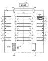
まず、図1および図2を参照して、実施形態にかかる自動バレー駐車システムの概略について説明する。ここで、自動バレー駐車システムとは、たとえば白線などといった所定の区画線Lによって開口部(車両Vの出入口)が設けられるように区画された1以上の駐車領域Rを有する駐車場Pにおいて、以下に説明するような自動駐車および自動出庫を含む自動バレー駐車を実現するためのシステムである。 First, the outline of the automatic valley parking system according to the embodiment will be described with reference to FIGS. 1 and 2. Here, the automatic valet parking system is defined in a parking lot P having one or more parking areas R partitioned by a predetermined marking line L such as a white line so that an opening (entrance / exit of a vehicle V) is provided. It is a system for realizing automatic valet parking including automatic parking and automatic warehousing as described in.
図1は、実施形態にかかる自動バレー駐車システムにおける自動駐車の一例を示した例示的かつ模式的な図であり、図2は、実施形態にかかる自動バレー駐車システムにおける自動出庫の一例を示した例示的かつ模式的な図である。 FIG. 1 is an exemplary and schematic diagram showing an example of automatic parking in the automatic valet parking system according to the embodiment, and FIG. 2 shows an example of automatic warehousing in the automatic valet parking system according to the embodiment. It is an exemplary and schematic diagram.
図1および図2に示されるように、自動バレー駐車においては、駐車場P内の所定の降車領域P1で車両Vから乗員Xが降車した後、所定の指示に応じて車両Vが降車領域P1から空きの駐車領域Rへ自動で移動して駐車する自動駐車(図1の矢印C1参照)と、当該自動駐車が完了した後、所定の呼び出しに応じて車両Vが駐車領域Rから出庫して所定の乗車領域P2へ自動で移動して停車する自動出庫(図2の矢印C2参照)と、が実行される。なお、所定の指示および所定の呼び出しは、乗員Xによる端末装置Tの操作によって実現される。 As shown in FIGS. 1 and 2, in automatic valley parking, after the occupant X gets off from the vehicle V in the predetermined disembarkation area P1 in the parking lot P, the vehicle V disembarks in response to the predetermined instruction P1. Automatic parking (see arrow C1 in FIG. 1) that automatically moves from the parking area R to an empty parking area R and parks the vehicle, and after the automatic parking is completed, the vehicle V leaves the parking area R in response to a predetermined call. Automatic warehousing (see arrow C2 in FIG. 2), which automatically moves to a predetermined boarding area P2 and stops, is executed. The predetermined instruction and the predetermined call are realized by the operation of the terminal device T by the occupant X.
また、図1および図2に示されるように、自動バレー駐車システムは、駐車場Pに設けられた管制装置101と、車両Vに搭載された車両制御システム102と、を有している。管制装置101と車両制御システム102とは、無線通信によって互いに通信可能に構成されている。
Further, as shown in FIGS. 1 and 2, the automatic valley parking system includes a
ここで、管制装置101は、駐車場P内の状況を撮像する1以上の監視カメラ103から得られる画像データや、駐車場P内に設けられる各種のセンサ(不図示)などから出力されるデータを受け取ることで駐車場P内の状況を監視し、監視結果に基づいて、駐車領域Rを管理するように構成されている。以下では、駐車場P内の状況を監視するために管制装置101が受け取る情報を総称してセンサデータと記載することがある。
Here, the
なお、実施形態において、駐車場Pにおける降車領域P1、乗車領域P2、および駐車領域Rの数や配置などは、図1および図2に示された例に制限されるものではない。実施形態の技術は、図1および図2に示された駐車場Pとは異なる様々な構成の駐車場に適用可能である。 In the embodiment, the number and arrangement of the disembarkation area P1, the boarding area P2, and the parking area R in the parking lot P are not limited to the examples shown in FIGS. 1 and 2. The technique of the embodiment is applicable to parking lots of various configurations different from the parking lot P shown in FIGS. 1 and 2.
次に、図3および図4を参照して、実施形態にかかる管制装置101および車両制御システム102の構成について説明する。なお、図3および図4に示される構成は、あくまで一例であり、実施形態にかかる管制装置101および車両制御システム102の構成は、種々に設定(変更)可能である。
Next, the configurations of the
まず、図3を参照して、実施形態にかかる管制装置101のハードウェア構成について説明する。
First, the hardware configuration of the
図3は、実施形態にかかる管制装置101のハードウェア構成を示した例示的かつ模式的なブロック図である。図3に示されるように、実施形態にかかる管制装置101は、PC(Personal Computer)などといった一般的な情報処理装置と同様のコンピュータ資源を有している。
FIG. 3 is an exemplary and schematic block diagram showing the hardware configuration of the
図3に示される例において、管制装置101は、CPU(Central Processing Unit)301と、ROM(Read Only Memory)302と、RAM(Random Access Memory)303と、通信インターフェース(I/F)304と、入出力インターフェース(I/F)305と、SSD(Solid State Drive)306と、を有している。これらのハードウェアは、データバス350を介して互いに接続されている。
In the example shown in FIG. 3, the
CPU301は、管制装置101を統括的に制御するハードウェアプロセッサである。CPU301は、ROM302などに記憶された各種の制御プログラム(コンピュータプログラム)を読み出し、当該各種の制御プログラムに規定されたインストラクションにしたがって各種の機能を実現する。
The
ROM302は、上述した各種の制御プログラムの実行に必要なパラメータなどを記憶する不揮発性の主記憶装置である。
The
RAM303は、CPU301の作業領域を提供する揮発性の主記憶装置である。
The
通信インターフェース304は、管制装置101と外部装置との間の通信を実現するインターフェースである。たとえば、通信インターフェース304は、管制装置101と車両V(車両制御システム102)との間の無線通信による信号の送受信を実現する。
The
入出力インターフェース305は、管制装置101と外部装置との接続を実現するインターフェースである。外部装置としては、たとえば、管制装置101のオペレータが使用する入出力デバイスなどが考えられる。
The input /
SSD306は、書き換え可能な不揮発性の補助記憶装置である。なお、実施形態にかかる管制装置101においては、補助記憶装置として、SSD306に替えて(またはSSD306に加えて)、HDD(Hard Disk Drive)が設けられてもよい。
次に、図4を参照して、実施形態にかかる車両制御システム102のシステム構成について説明する。
Next, the system configuration of the
図4は、実施形態にかかる車両制御システム102のシステム構成を示した例示的かつ模式的なブロック図である。図4に示されるように、車両制御システム102は、制動システム401と、加速システム402と、操舵システム403と、変速システム404と、障害物センサ405と、走行状態センサ406と、通信インターフェース(I/F)407と、車載カメラ408と、モニタ装置409と、車両制御装置410と、車載ネットワーク450と、を有している。
FIG. 4 is an exemplary and schematic block diagram showing the system configuration of the
制動システム401は、車両Vの減速を制御する。制動システム401は、制動部401aと、制動制御部401bと、制動部センサ401cと、を有している。
The
制動部401aは、たとえば、ブレーキペダルなどを含んだ、車両Vを減速させるための装置である。 The braking unit 401a is a device for decelerating the vehicle V, including, for example, a brake pedal.
制動制御部401bは、たとえば、CPUなどといったハードウェアプロセッサを有したコンピュータにより構成されるECU(Electronic Control Unit)である。制動制御部401bは、車両制御装置410からの指示に基づいてアクチュエータ(不図示)を駆動し、制動部401aを作動させることで、車両Vの減速度合を制御する。
The
制動部センサ401cは、制動部401aの状態を検出するための装置である。たとえば、制動部401aがブレーキペダルを含む場合、制動部センサ401cは、制動部401aの状態として、ブレーキペダルの位置または当該ブレーキペダルに作用している圧力を検出する。制動部センサ401cは、検出した制動部401aの状態を車載ネットワーク450に出力する。
The
加速システム402は、車両Vの加速を制御する。加速システム402は、加速部402aと、加速制御部402bと、加速部センサ402cと、を有している。
The
加速部402aは、たとえば、アクセルペダルなどを含んだ、車両Vを加速させるための装置である。 The acceleration unit 402a is a device for accelerating the vehicle V, including, for example, an accelerator pedal.
加速制御部402bは、たとえば、CPUなどといったハードウェアプロセッサを有したコンピュータにより構成されるECUである。加速制御部402bは、車両制御装置410からの指示に基づいてアクチュエータ(不図示)を駆動し、加速部402aを作動させることで、車両Vの加速度合を制御する。
The acceleration control unit 402b is an ECU configured by a computer having a hardware processor such as a CPU, for example. The acceleration control unit 402b controls the acceleration ratio of the vehicle V by driving an actuator (not shown) based on an instruction from the
加速部センサ402cは、加速部402aの状態を検出するための装置である。たとえば、加速部402aがアクセルペダルを含む場合、加速部センサ402cは、アクセルペダルの位置または当該アクセルペダルに作用している圧力を検出する。加速部センサ402cは、検出した加速部402aの状態を車載ネットワーク450に出力する。
The acceleration unit sensor 402c is a device for detecting the state of the acceleration unit 402a. For example, when the acceleration unit 402a includes an accelerator pedal, the acceleration unit sensor 402c detects the position of the accelerator pedal or the pressure acting on the accelerator pedal. The acceleration unit sensor 402c outputs the detected state of the acceleration unit 402a to the vehicle-mounted
操舵システム403は、車両Vの進行方向を制御する。操舵システム403は、操舵部403aと、操舵制御部403bと、操舵部センサ403cと、を有している。
The
操舵部403aは、たとえば、ステアリングホイールやハンドルなどを含んだ、車両Vの転舵輪を転舵させる装置である。 The steering unit 403a is a device for steering the steering wheels of the vehicle V, including, for example, a steering wheel and a steering wheel.
操舵制御部403bは、たとえば、CPUなどといったハードウェアプロセッサを有したコンピュータにより構成されるECUである。操舵制御部403bは、車両制御装置410からの指示に基づいてアクチュエータ(不図示)を駆動し、操舵部403aを作動させることで、車両Vの進行方向を制御する。
The
操舵部センサ403cは、操舵部403aの状態を検出するための装置である。たとえば、操舵部403aがステアリングホイールを含む場合、操舵部センサ403cは、ステアリングホイールの位置または当該ステアリングホイールの回転角度を検出する。なお、操舵部403aがハンドルを含む場合、操舵部センサ403cは、ハンドルの位置または当該ハンドルに作用している圧力を検出してもよい。操舵部センサ403cは、検出した操舵部403aの状態を車載ネットワーク450に出力する。
The steering unit sensor 403c is a device for detecting the state of the steering unit 403a. For example, when the steering unit 403a includes a steering wheel, the steering unit sensor 403c detects the position of the steering wheel or the rotation angle of the steering wheel. When the steering unit 403a includes a steering wheel, the steering unit sensor 403c may detect the position of the steering wheel or the pressure acting on the steering wheel. The steering unit sensor 403c outputs the detected state of the steering unit 403a to the vehicle-mounted
変速システム404は、車両Vの変速比を制御する。変速システム404は、変速部404aと、変速制御部404bと、変速部センサ404cと、を有している。
The
変速部404aは、たとえば、シフトレバーなどを含んだ、車両Vの変速比を変更するための装置である。
The
変速制御部404bは、たとえば、CPUなどといったハードウェアプロセッサを有したコンピュータにより構成されるECUである。変速制御部404bは、車両制御装置410からの指示に基づいてアクチュエータ(不図示)を駆動し、変速部404aを作動させることで、車両Vの変速比を制御する。
The shift control unit 404b is an ECU configured by a computer having a hardware processor such as a CPU, for example. The shift control unit 404b controls the gear ratio of the vehicle V by driving an actuator (not shown) based on an instruction from the
変速部センサ404cは、変速部404aの状態を検出するための装置である。たとえば、変速部404aがシフトレバーを含む場合、変速部センサ404cは、シフトレバーの位置または当該シフトレバーに作用している圧力を検出する。変速部センサ404cは、検出した変速部404aの状態を車載ネットワーク450に出力する。
The
障害物センサ405は、車両Vの周囲に存在しうる障害物に関する情報を検出するための装置である。障害物センサ405は、たとえば、障害物までの距離を検出するソナーなどといった測距センサを含んでいる。障害物センサ405は、検出した情報を車載ネットワーク450に出力する。
The
走行状態センサ406は、車両Vの走行状態を検出するための装置である。走行状態センサ406は、たとえば、車両Vの車輪速を検出する車輪速センサや、車両Vの前後方向または左右方向の加速度を検出する加速度センサや、車両Vの旋回速度(角速度)を検出するジャイロセンサなどを含んでいる。走行状態センサ406は、検出した走行状態を車載ネットワーク450に出力する。
The traveling
通信インターフェース407は、車両制御システム102と外部装置との間の通信を実現するインターフェースである。たとえば、通信インターフェース407は、車両制御システム102と管制装置101との間の無線通信による信号の送受信や、車両制御システム102と端末装置Tとの間の無線通信による信号の送受信などを実現する。
The
車載カメラ408は、車両Vの周辺の状況を撮像するための装置である。たとえば、車載カメラ408は、車両Vの前方、後方、および側方(左右両方)の路面を含む領域を撮像するように複数設けられる。車載カメラ408によって得られた画像データは、車両Vの周辺の状況の監視(障害物の検出も含む)に使用される。車載カメラ408は、得られた画像データを車両制御装置410に出力する。なお、以下では、車載カメラ408から得られる画像データと、車両制御システム102に設けられる上述した各種のセンサから得られるデータと、を総称してセンサデータと記載することがある。
The in-
モニタ装置409は、車両Vの車室内のダッシュボードなどに設けられる。モニタ装置409は、表示部409aと、音声出力部409bと、操作入力部409cと、を有している。
The
表示部409aは、車両制御装置410の指示に応じて画像を表示するための装置である。表示部409aは、たとえば、液晶ディスプレイ(LCD:Liquid Crystal Display)や、有機ELディスプレイ(OELD:Organic Electroluminescent Display)などによって構成される。
The display unit 409a is a device for displaying an image in response to an instruction from the
音声出力部409bは、車両制御装置410の指示に応じて音声を出力するための装置である。音声出力部409bは、たとえば、スピーカによって構成される。
The
操作入力部409cは、車両V内の乗員の入力を受け付けるための装置である。操作入力部409cは、たとえば、表示部409aの表示画面に設けられるタッチパネルや、物理的な操作スイッチなどによって構成される。操作入力部409cは、受け付けた入力を車載ネットワーク450に出力する。
The operation input unit 409c is a device for receiving the input of the occupant in the vehicle V. The operation input unit 409c is composed of, for example, a touch panel provided on the display screen of the display unit 409a, a physical operation switch, or the like. The operation input unit 409c outputs the received input to the in-
車両制御装置410は、車両制御システム102を統括的に制御するための装置である。車両制御装置410は、CPU410aや、ROM410b、RAM410cなどといったコンピュータ資源を有したECUである。
The
より具体的に、車両制御装置410は、CPU410aと、ROM410bと、RAM410cと、SSD410dと、表示制御部410eと、音声制御部410fと、を有している。
More specifically, the
CPU410aは、車両制御装置410を統括的に制御するハードウェアプロセッサである。CPU410aは、ROM410bなどに記憶された各種の制御プログラム(コンピュータプログラム)を読み出し、当該各種の制御プログラムに規定されたインストラクションにしたがって各種の機能を実現する。
The CPU 410a is a hardware processor that collectively controls the
ROM410bは、上述した各種の制御プログラムの実行に必要なパラメータなどを記憶する不揮発性の主記憶装置である。 The ROM 410b is a non-volatile main storage device that stores parameters and the like necessary for executing the various control programs described above.
RAM410cは、CPU410aの作業領域を提供する揮発性の主記憶装置である。 The RAM 410c is a volatile main storage device that provides a working area for the CPU 410a.
SSD410dは、書き換え可能な不揮発性の補助記憶装置である。なお、実施形態にかかる車両制御装置410においては、補助記憶装置として、SSD410dに替えて(またはSSD410dに加えて)、HDDが設けられてもよい。
The SSD410d is a rewritable non-volatile auxiliary storage device. In the
表示制御部410eは、車両制御装置410で実行される各種の処理のうち、主として、車載カメラ408から得られた画像データに対する画像処理や、モニタ装置409の表示部409aに出力する画像データの生成などを司る。
The display control unit 410e mainly performs image processing on the image data obtained from the in-
音声制御部410fは、車両制御装置410で実行される各種の処理のうち、主として、モニタ装置409の音声出力部409bに出力する音声データの生成などを司る。
The voice control unit 410f mainly controls the generation of voice data to be output to the
車載ネットワーク450は、制動システム401と、加速システム402と、操舵システム403と、変速システム404と、障害物センサ405と、走行状態センサ406と、通信インターフェース407と、モニタ装置409の操作入力部409cと、車両制御装置410と、を通信可能に接続する。
The in-
ところで、自動バレー駐車システムにおける自動駐車および自動出庫のような自動走行を実現するためには、自動走行中における車両Vの現在位置を正確に把握することが重要となる。この点に関して、従来から、車輪速センサなどの検出値を用いて車両Vの現在位置を推定する手法(いわゆるオドメトリ)が知られている。しかしながら、この手法においては、車両Vの移動距離が大きくなる程、推定結果の誤差が累積されて大きくなっていくため、車両Vの現在位置を正確に把握することができない場合がある。 By the way, in order to realize automatic parking such as automatic parking and automatic warehousing in an automatic valley parking system, it is important to accurately grasp the current position of the vehicle V during automatic driving. Regarding this point, a method (so-called odometry) for estimating the current position of the vehicle V by using a detected value of a wheel speed sensor or the like has been conventionally known. However, in this method, as the moving distance of the vehicle V increases, the error of the estimation result is accumulated and increases, so that the current position of the vehicle V may not be accurately grasped.
そこで、実施形態では、車両制御装置410に以下のような機能を持たせることで、自動駐車および自動出庫における自動走行中に車両Vの現在位置を正確に把握することを実現する。つまり、実施形態において、車両制御装置410は、「車両位置推定装置」の一例である。
Therefore, in the embodiment, by providing the
図5は、実施形態にかかる管制装置101および車両制御装置410の機能を示した例示的かつ模式的なブロック図である。この図5に示される機能は、ソフトウェアとハードウェアとの協働によって実現される。つまり、図5に示される例において、管制装置101の機能は、CPU301がROM302などに記憶された所定の制御プログラムを読み出して実行した結果として実現され、車両制御装置410の機能は、CPU410aがROM410bなどに記憶された所定の制御プログラムを読み出して実行した結果として実現される。なお、実施形態では、図5に示される管制装置101および車両制御装置410の一部または全部が専用のハードウェア(回路)のみによって実現されてもよい。
FIG. 5 is an exemplary and schematic block diagram showing the functions of the
図5に示されるように、実施形態にかかる管制装置101は、機能的構成として、通信制御部511と、センサデータ取得部512と、駐車場データ管理部513と、誘導経路生成部514と、を有している。
As shown in FIG. 5, the
通信制御部511は、車両制御装置410との間で実行される無線通信を制御する。たとえば、通信制御部511は、車両制御装置410との間で所定のデータを送受信することで車両制御装置410の認証を行ったり、自動駐車および自動出庫が完了した際に車両制御装置410から出力される所定の完了通知を受信したり、後述する駐車場Pの地図データや誘導経路などを必要に応じて車両制御装置410に送信したりする。
The communication control unit 511 controls the wireless communication executed with the
センサデータ取得部512は、駐車場P内に設けられる監視カメラ103や各種のセンサ(不図示)などから上述したセンサデータを取得する。センサデータ取得部512により取得されるセンサデータ(特に監視カメラ103から得られる画像データ)は、たとえば、駐車領域Rの空き状況の把握などに使用することが可能である。
The sensor
駐車場データ管理部513は、駐車場Pに関するデータ(情報)を管理する。たとえば、駐車場データ管理部513は、駐車場Pの地図データや、駐車領域Rの空き状況などを管理する。たとえば、駐車場データ管理部513は、自動駐車が行われる際、空いている駐車領域Rの中から1つの駐車領域Rを選択し、選択した1つの駐車領域Rを、自動駐車における車両Vの到達目標である目標駐車領域として指定する。また、駐車場データ管理部513は、自動駐車が完了した後に車両Vが再び移動して駐車領域Rが変更された場合、センサデータ取得部512から取得されるセンサデータに基づいて、変更後の駐車領域Rを特定する。
The parking lot data management unit 513 manages data (information) related to the parking lot P. For example, the parking lot data management unit 513 manages the map data of the parking lot P, the availability of the parking area R, and the like. For example, when automatic parking is performed, the parking lot data management unit 513 selects one parking area R from the vacant parking areas R, and uses the selected parking area R as the vehicle V in the automatic parking. Designate as the target parking area, which is the goal to be reached. Further, when the vehicle V moves again and the parking area R is changed after the automatic parking is completed, the parking lot data management unit 513 changes the parking area based on the sensor data acquired from the sensor
誘導経路生成部514は、自動駐車および自動出庫が行われる際に車両制御装置410に指示する誘導経路を生成する。より具体的に、誘導経路生成部514は、自動駐車が行われる際においては、降車領域P1から目標駐車領域へ至る概略的な経路を誘導経路として生成し、自動出庫が行われる際においては、目標駐車領域(自動駐車後に車両Vが移動している場合には車両Vが現在駐車している駐車領域R)から乗車領域P2へ至る概略的な経路を誘導経路として生成する。
The guidance
一方、図5に示されるように、実施形態にかかる車両制御装置410は、機能的構成として、通信制御部521と、センサデータ取得部522と、走行制御部523と、位置推定部524と、を有している。
On the other hand, as shown in FIG. 5, the
通信制御部521は、管制装置101との間で実行される無線通信を制御する。たとえば、通信制御部521は、管制装置101との間で所定のデータを送受信することで車両制御装置410の認証を行ったり、自動駐車および自動出庫が完了した際に所定の完了通知を管制装置101に送信したり、駐車場Pの地図データや誘導経路などを必要に応じて管制装置101から受信したりする。したがって、通信制御部521は、駐車場Pの地図データを取得する地図データ取得部として機能する。
The communication control unit 521 controls the wireless communication executed with the
なお、実施形態において、地図データは、たとえば、駐車場Pの路面に設置されうる各種の路面標示(具体例は後述する)の絶対位置を特定するための情報を含んでいる。ここで言及している絶対位置は、路面標示が有する方向性(絶対方位)も含みうる概念である。つまり、路面標示が所定の向き(方向性)を持った線状の標示を含んでいる場合、地図データからは、路面標示が設けられた絶対位置のみならず、路面標示に含まれる線状の標示によって表される絶対方位も特定可能である。 In the embodiment, the map data includes, for example, information for specifying the absolute positions of various road markings (specific examples will be described later) that can be installed on the road surface of the parking lot P. The absolute position referred to here is a concept that can include the directionality (absolute orientation) of the road marking. That is, when the road marking includes a linear marking having a predetermined direction (direction), the map data shows not only the absolute position where the road marking is provided but also the linear marking included in the road marking. The absolute orientation represented by the markings can also be specified.
センサデータ取得部522は、車載カメラ408によって得られる画像データを取得する画像データ取得部の一例であり、当該画像データと、車両制御システム102に設けられる各種のセンサから出力されるデータと、を含むセンサデータを取得する。センサデータ取得部522により取得されるセンサデータは、たとえば、管制装置101から受信された誘導経路を基にした実際の走行経路(駐車経路および出庫経路を含む)の生成や、当該走行経路に沿って実際に走行する際に必要となる各種のパラメータ(車速や舵角、進行方向など)の設定など、次の走行制御部523により実行される車両Vの各種の走行制御に使用することが可能である。
The sensor data acquisition unit 522 is an example of an image data acquisition unit that acquires image data obtained by the in-
走行制御部523は、制動システム401や加速システム402、操舵システム403、変速システム404などを制御することで、降車領域P1からの発進制御や、降車領域P1から駐車領域Rへの走行制御(駐車制御を含む)、駐車領域Rから乗車領域P2への走行制御(出庫制御を含む)、乗車領域P2への停車制御などといった、自動駐車および自動出庫を実現するための各種の走行制御を実行するように、車両Vの走行状態を制御する。
The
位置推定部524は、自動駐車および自動出庫における車両Vの自動走行中に、上述したオドメトリによって車両Vの現在位置を推定する。そして、位置推定部524は、センサデータ取得部522により取得される画像データに基づいて、オドメトリによる推定結果を、その累積誤差をキャンセルするように補正することで、車両Vの現在位置(実位置)を推定する。なお、ここで言及している実位置は、車両Vの向き(実方位)も含む概念である。
The
すなわち、実施形態において、位置推定部524は、自動走行の実施中に、まず、センサデータ取得部522により取得される画像データから、車両Vの周辺に位置する路面標示に関する路面標示データを検出することで、画像データ上における車両Vに対する路面標示の相対位置を算出する。そして、位置推定部524は、路面標示の相対位置に基づいて特定される路面標示の計算上の絶対位置と、通信制御部531により取得される駐車場データに基づく路面標示の正規の絶対位置と、の差分に基づいて、オドメトリに基づく推定結果を補正し、補正後の値を、車両Vの現在位置(実位置)の正規の推定値として設定する。なお、ここで言及している相対位置は、車両Vに対する路面標示の相対方位も含みうる概念である。
That is, in the embodiment, the
たとえば、実施形態において、位置推定部524は、以下に説明する例のように、自動走行によって車両Vが区画線Lと交差する方向に走行している場合に、車両Vの側方の状況を表す画像データであるサイド画像データに基づいて、区画線Lのうち車両Vに近い側(駐車領域Rの開口部側)の端部Eの位置と、区画線Lの向きと、に関する路面標示データを検出する。そして、位置推定部524は、検出した路面標示データに基づいて、車両Vを基準とした区画線Lの端部Eの位置を表す相対位置と、車両Vを基準とした区画線Lの向きを表す相対方位と、算出する。そして、位置推定部524は、算出した区画線Lの相対位置および相対方位と、駐車場Pの地図データに基づく区画線Lの絶対位置および絶対方位と、に基づいて、オドメトリに基づく推定結果を補正し、車両Vの現在位置(実位置および実方位)を推定する。
For example, in the embodiment, the
図6は、実施形態にかかる車両制御装置410の位置推定部524により実施されうる現在位置の推定方法の一例を説明するための例示的かつ模式的な図である。図6に示される例では、車両Vが、当該車両Vの左側方に位置する3本の区画線L61〜L63と交差する方向に走行している。
FIG. 6 is an exemplary and schematic diagram for explaining an example of a current position estimation method that can be implemented by the
図6に示される例では、車両Vの左側部(たとえばサイドミラー)に設けられる車載カメラ408の撮像範囲が、区画線L62の端部E62を含む領域A61に対応している。したがって、車両Vの左側部に設けられる車載カメラ408によって得られるサイド画像データに対して白線検出処理などの画像認識処理を実施すれば、区画線L62の位置および向きに関する路面標示データを検出することができる。そして、検出した路面標示データを利用すれば、車両Vを基準とした、区画線L62の相対位置(より具体的には区画線L62の端部Eの相対位置)と、区画線L62の相対方位(より具体的には区画線L62の延びる方向を表す相対方位)と、を算出することができる。そして、算出した相対位置および相対方位と、オドメトリに基づく車両Vの位置および方位の推定結果と、を利用すれば、区画線L62の計算上の絶対位置および絶対方位を特定することができる。
In the example shown in FIG. 6, the imaging range of the vehicle-mounted
ここで、区画線L62の計算上の絶対位置(および絶対方位)は、上記のように、オドメトリに基づく推定結果を利用して特定されるものであるので、オドメトリによる累積誤差の影響が含まれうる。一方、前述したように、管制装置101で管理される駐車場Pの地図データは、路面標示の正規の絶対位置(および絶対方位)を特定するための情報を含んでいるため、地図データには、路面標示としての区画線L62の正規の絶対位置(および絶対方位)を特定するための区画線データが含まれる。
Here, since the calculated absolute position (and absolute orientation) of the lane marking L62 is specified by using the estimation result based on the odometry as described above, the influence of the cumulative error due to the odometry is included. sell. On the other hand, as described above, since the map data of the parking lot P managed by the
そこで、実施形態において、通信制御部521は、管制装置101から、地図データとしての区画線データを取得する。そして、位置推定部524は、上記の相対位置(相対方位を含む)に基づいて特定される区画線L62の計算上の絶対位置と、区画線データに基づいて特定される区画線L62の正規の絶対位置(絶対方位を含む)と、の差分をとり、当該差分に基づいて、オドメトリによる推定結果のずれを補正し、補正後の値を、車両Vの実位置(実方位を含む)として推定する。なお、このような相対位置および相対方位の両方を考慮した補正については、後で図面を参照しながらより具体的に説明するため、ここではこれ以上の説明を省略する。
Therefore, in the embodiment, the communication control unit 521 acquires the lane marking data as map data from the
上述した図6に示される例においては、サイド画像データから1つの路面標示(区画線L62)が検出され、当該1つの路面標示の相対位置および相対方位の両方が算出されることで、車両Vの実位置および実方位が推定されている。しかしながら、実施形態では、以下に説明するように、サイド画像データから少なくとも2つの路面標示を検出することができれば、当該少なくとも2つの路面標示の相対位置のみを算出するだけ(相対方位は算出しない)で、当該少なくとも2つの路面標示の位置関係に基づいて、車両Vの実位置および実方位を推定することも可能である。 In the example shown in FIG. 6 described above, one road marking (section line L62) is detected from the side image data, and both the relative position and the relative direction of the one road marking are calculated to obtain the vehicle V. The actual position and orientation of the are estimated. However, in the embodiment, as described below, if at least two road markings can be detected from the side image data, only the relative positions of the at least two road markings are calculated (the relative orientation is not calculated). Therefore, it is also possible to estimate the actual position and the actual direction of the vehicle V based on the positional relationship of at least two road markings.
図7は、実施形態にかかる車両制御装置410の位置推定部524により実施されうる現在位置の推定方法の図6とは異なる一例を説明するための例示的かつ模式的な図である。図7に示される例では、車両Vが、当該車両Vの左側方に位置する3本の区画線L71〜L73および車両Vの右側方に位置する3本の区画線L74〜L76と交差する方向に走行している。
FIG. 7 is an exemplary and schematic diagram for explaining an example different from FIG. 6 of the current position estimation method that can be carried out by the
図7に示される例では、車両Vの左側部(たとえばサイドミラー)に設けられる車載カメラ408の撮像範囲が、区画線L72の端部E72を含む領域A71に対応しており、車両の右側部(たとえばサイドミラー)に設けられる車載カメラ408の撮像範囲が、区画線L76の端部E76を含む領域A72に対応している。
In the example shown in FIG. 7, the imaging range of the vehicle-mounted
したがって、図7に示される例では、上記の2つの車載カメラ408によって得られる一対のサイド画像データに対して白線検出処理などの画像認識処理を行えば、区画線L72およびL76の端部E72およびE76の位置に関する路面標示データを検出することができる。そして、検出した路面標示データを利用すれば、車両Vを基準とした、区画線L72の相対位置(より具体的には区画線L72の端部E72の相対位置)と、区画線L76の相対位置(より具体的には区画線L76の端部E76の相対位置)と、を算出することができる。そして、算出した相対位置と、オドメトリに基づく推定結果と、を利用すれば、区画線L72およびL76の端部E72およびE76の計算上の絶対位置を特定することができる。
Therefore, in the example shown in FIG. 7, if image recognition processing such as white line detection processing is performed on the pair of side image data obtained by the above two in-
位置推定部524は、上記の相対位置に基づいて特定される区画線L72およびL76の端部E72およびE76の計算上の絶対位置と、地図データ(区画線データ)に基づいて特定される区画線L72およびL76の端部E72およびE76の正規の絶対位置と、を照合することで、オドメトリによる車両Vの位置および向き(方位)の推定結果のずれを補正する。なお、図7に示される例では、上述した図6に示される例と異なり、照合の対象となるポイントが2つであるので、これら2つのポイントと車両Vとの位置関係が特定されれば、各ポイントの方位を個別に特定することなく、車両Vの向き(方位)の推定結果のずれを補正することが可能である。
The
このように、図7に示される例によれば、区画線L72およびL76の相対方位を算出することなく、区画線L72およびL76の相対位置のみを算出するだけで、車両Vの実位置および実方位を推定することができる。なお、このような相対方位を含まない相対位置のみを用いた補正の方法については、後で図面を参照しながらより具体的に説明するため、ここではこれ以上の説明を省略する。 As described above, according to the example shown in FIG. 7, the actual position and the actual position of the vehicle V are calculated only by calculating the relative positions of the lane markings L72 and L76 without calculating the relative directions of the lane markings L72 and L76. The orientation can be estimated. The method of correction using only the relative position not including the relative orientation will be described more specifically later with reference to the drawings, and further description thereof will be omitted here.
上述した図6および図7に示される例では、2つのサイド画像データ(左サイド画像データおよび右サイド画像データ)からそれぞれ1つずつ合計2つの路面標示(区画線L72およびL76)が検出され、これら2つの路面標示の相対位置の位置関係が算出されることで、車両Vの実位置および実方位が推定されている。しかしながら、実施形態では、以下に説明するように、1つのサイド画像データから複数の路面標示を同時に検出し、これら複数の路面標示の相対位置の位置関係を算出することで、車両Vの実位置および実方位を推定することも可能である。 In the example shown in FIGS. 6 and 7 described above, a total of two road markings (section lines L72 and L76) are detected, one from each of the two side image data (left side image data and right side image data). By calculating the positional relationship between the relative positions of these two road markings, the actual position and actual orientation of the vehicle V are estimated. However, in the embodiment, as described below, a plurality of road markings are simultaneously detected from one side image data, and the positional relationship of the relative positions of the plurality of road markings is calculated to calculate the actual position of the vehicle V. And it is also possible to estimate the actual orientation.
図8は、実施形態にかかる車両制御装置410の位置推定部524により実施されうる現在位置の推定方法の図6および図7とは異なる一例を説明するための例示的かつ模式的な図である。図8に示される例では、車両Vが、当該車両Vの左側方に位置する3本の区画線L81〜L83と交差する方向に走行している。
FIG. 8 is an exemplary and schematic diagram for explaining an example different from FIGS. 6 and 7 of the current position estimation method that can be carried out by the
図8に示される例では、車両Vの左側部(たとえばサイドミラー)に設けられる車載カメラ408の撮像範囲は、区画線L81の端部E81と、区画線L82の端部E82と、を含む領域A81に対応している。したがって、図8に示される例では、車両Vの左側部に設けられる車載カメラ408によって得られる1つのサイド画像データに対して白線検出処理などの画像認識処理を行えば、区画線L81およびL82の端部E81およびE82の位置に関する路面標示データを検出することができる。そして、検出した路面標示データを利用すれば、車両Vを基準とした、区画線L81の相対位置(より具体的には区画線L81の端部E81の相対位置)と、区画線L82の相対位置(より具体的には区画線L82の端部E82の相対位置)と、を算出することができる。そして、算出した相対位置と、オドメトリに基づく推定結果と、を利用すれば、区画線L81およびL82の端部E81およびE82の計算上の絶対位置を特定することができる。
In the example shown in FIG. 8, the imaging range of the vehicle-mounted
位置推定部524は、上記の相対位置に基づいて特定される区画線L81およびL82の端部E81およびE82の計算上の絶対位置と、地図データ(区画線データ)に基づいて特定される区画線L81およびL82の端部E81およびE82の正規の絶対位置と、を照合することで、オドメトリによる車両Vの位置および向き(方位)の推定結果のずれを補正する。図8に示される例によれば、1つのサイド画像データのみを用いて、上述した図7に示される例と同様の推定、すなわち相対方位を含まない相対位置のみに基づく車両Vの実位置および実方位の推定を行うことができる。
The
上述した図8に示される例では、路面標示として区画線Lが用いられている。しかしながら、実施形態では、以下に説明するように、区画線L以外の路面標示(所定方向に延びる線分LSを含んだマーカM)を用いることも可能である。 In the example shown in FIG. 8 described above, the lane marking L is used as the road marking. However, in the embodiment, as described below, it is also possible to use a road marking (marker M including a line segment LS extending in a predetermined direction) other than the lane marking L.
図9は、実施形態にかかる車両制御装置410の位置推定部524により実施されうる現在位置の推定方法の図6〜図8とは異なる一例を説明するための例示的かつ模式的な図である。図9に示される例では、車両Vが、当該車両Vの左側に位置する3つの区画線L91〜L93と交差するように走行している。
FIG. 9 is an exemplary and schematic diagram for explaining an example different from FIGS. 6 to 8 of the current position estimation method that can be carried out by the
ここで、図9に示される例では、路面標示として、3つの区画線L91〜L93に加えて、2つのマーカM91およびM92が設置されている。マーカM91は、線分LS91を含み、区画線L91およびL92の間に設置されている。また、マーカM92は、線分LS92を含み、区画線L92およびL93の間に設置されている。 Here, in the example shown in FIG. 9, two markers M91 and M92 are installed in addition to the three lane markings L91 to L93 as road markings. The marker M91 includes the line segment LS91 and is installed between the lane markings L91 and L92. Further, the marker M92 includes a line segment LS92 and is installed between the division lines L92 and L93.
図9に示される例では、車両Vの左側部(たとえばサイドミラー)に設けられる車載カメラ408の撮像範囲が、マーカM91およびM92を含む領域A91に対応している。したがって、車両Vの左側部に設けられる車載カメラ408によって得られるサイド画像データに対して白線検出処理などの画像認識処理を実施すれば、マーカM91およびM92のそれぞれの位置(たとえば中心位置)と、マーカM91およびM92に含まれる線分LS91およびLS92のそれぞれの向きと、に関する路面標示データを検出することができる。そして、検出した路面標示データを利用すれば、車両Vを基準とした、マーカM91およびM92の相対位置(マーカM91およびM92の中心の相対位置)と、マーカM91およびM92の方位(線分LS91およびLS92の向きを表す相対方位)と、を算出することができる。そして、算出した相対位置および相対方位と、オドメトリに基づく車両Vの位置および方位の推定結果と、を利用すれば、マーカM91およびM92の計算上の絶対位置および絶対方位を特定することができる。
In the example shown in FIG. 9, the imaging range of the vehicle-mounted
上述した図6などに示される例と同様、マーカM91およびM92の計算上の相対位置(および相対方位)は、上記のように、オドメトリに基づく推定結果を利用して特定されるものであるので、オドメトリによる累積誤差の影響が含まれうる。一方、前述したように、管制装置101で管理される駐車場Pの地図データは、路面標示の正規の絶対位置(および絶対方位)を特定するための情報を含んでいるため、地図データには、路面標示としてのマーカM91およびM92の正規の絶対位置(および絶対方位)を特定するためのマーカデータが含まれる。
As in the example shown in FIG. 6 and the like described above, the calculated relative positions (and relative orientations) of the markers M91 and M92 are specified by using the estimation result based on the odometry as described above. , The effect of cumulative error due to odometry may be included. On the other hand, as described above, since the map data of the parking lot P managed by the
そこで、実施形態において、通信制御部521は、管制装置101から、地図データとしてのマーカデータを取得する。そして、位置推定部524は、上記の相対位置(相対方位を含む)に基づいて特定されるマーカM91およびM92の計算上の絶対位置と、マーカデータに基づいて特定されるマーカM91およびM92の正規の絶対位置(絶対方位を含む)と、の差分をとり、当該差分に基づいて、オドメトリによる推定結果のずれを補正し、補正後の値を、車両Vの実位置(実方位を含む)として推定する。
Therefore, in the embodiment, the communication control unit 521 acquires marker data as map data from the
上述した図6〜図9に示される例では、区画線LおよびマーカMの一方のみが用いられている。しかしながら、実施形態では、区画線LおよびマーカMの両方を用いることも可能である。特に、以下に説明するような車両Vの旋回時では、現在位置の推定精度の向上が望まれるため、区画線LおよびマーカMの両方を考慮して、推定のもととなるデータを増やすのが有益である。 In the examples shown in FIGS. 6 to 9 described above, only one of the lane marking L and the marker M is used. However, in the embodiment, it is also possible to use both the lane marking L and the marker M. In particular, when the vehicle V is turning as described below, it is desired to improve the estimation accuracy of the current position. Therefore, the data that is the basis of the estimation is increased in consideration of both the lane marking L and the marker M. Is beneficial.
図10は、実施形態にかかる車両制御装置410の位置推定部524により実施されうる現在位置の推定方法の図6〜図9とは異なる一例を説明するための例示的かつ模式的な図である。図10に示される例では、車両Vが、区画線L101およびL102と、当該区画線L101およびL102の近傍にL字状に配置されたマーカM101〜M103とを内側にして、矢印C100に沿って左回りに旋回している。なお、マーカM101〜M103の形状は、図10に示される例に制限されるものではない。
FIG. 10 is an exemplary and schematic diagram for explaining an example different from FIGS. 6 to 9 of the current position estimation method that can be carried out by the
図10に示される例において、位置推定部524は、車両Vの旋回時に、車両Vの旋回の内側の状況を表す画像データである内側画像データをセンサデータ取得部522により取得する。そして、通信制御部521は、管制装置101から、地図データとして、区画線データおよびマーカデータの両方を取得する。そして、位置推定部524は、内側画像データから、区画線L101およびL102とマーカM101〜M103とに関する路面標示データを検出し、検出した路面標示データに基づいて、車両Vに対する区画線L101およびL102とマーカM101〜M103との相対位置を算出する。
In the example shown in FIG. 10, when the vehicle V turns, the
そして、位置推定部524は、算出した相対位置と、オドメトリに基づく車両Vの位置および方位の推定結果と、に基づいて、区画線L101およびL102とマーカM101〜M103との計算上の絶対位置を特定する。そして、位置推定部524は、特定した計算上の絶対位置と、区画線データおよびマーカデータから特定される正規の絶対位置と、の差分に基づいて、オドメトリによる推定結果のずれを補正し、補正後の値を、車両Vの実位置(実方位を含む)として推定する。
Then, the
なお、図10に示される例では、3つのマーカM(M101〜M103)がL字状に配置されている。しかしながら、実施形態では、旋回する車両Vの車載カメラの撮像範囲に入っていれば、マーカMの個数および配置は、種々に設定(変更)可能である。また、図10に示される例では、区画線LとマーカMとの両方が考慮されることで車両Vの実位置が推定されている。しかしながら、実施形態では、区画線LおよびマーカMの少なくとも一方が考慮されれば、区画線Lのみ、あるいはマーカMのみが考慮されることで車両Vの実位置が推定されてもよい。この場合、通信制御部521は、地図データとして、区画線データおよびマーカデータのうち、考慮すべき路面標示データに対応する方のデータを取得すればよい。 In the example shown in FIG. 10, three markers M (M101 to M103) are arranged in an L shape. However, in the embodiment, the number and arrangement of the markers M can be variously set (changed) as long as they are within the imaging range of the in-vehicle camera of the turning vehicle V. Further, in the example shown in FIG. 10, the actual position of the vehicle V is estimated by considering both the lane marking L and the marker M. However, in the embodiment, if at least one of the lane marking L and the marker M is considered, the actual position of the vehicle V may be estimated by considering only the lane marking L or only the marker M. In this case, the communication control unit 521 may acquire, as map data, the data corresponding to the road marking data to be considered, out of the lane marking data and the marker data.
また、図6〜図10に示される例では、端部が丸いU字状に構成された区画線Lが例示されている。しかしながら、実施形態では、端部が矩形状に構成された区画線Lが用いられてもよい。また、実施形態では、区画線LおよびマーカMの相対位置の検出に、車両Vの側部に設けられる車載カメラ408によって得られるサイド画像データのみならず、車両Vの前部(たとえばフロントバンパ)に設けられる車載カメラ408によって得られるフロント画像データや、後部(たとえばリヤバンパ)に設けられる車載カメラ408によって得られるリヤ画像データなどが用いられてもよい。
Further, in the examples shown in FIGS. 6 to 10, a lane marking L having a U-shaped end is illustrated. However, in the embodiment, a lane marking L having a rectangular end may be used. Further, in the embodiment, not only the side image data obtained by the in-
ここで、上述した図6〜図10において実施されうる補正の具体的内容について図面を参照しながら詳細に説明する。 Here, the specific contents of the corrections that can be performed in FIGS. 6 to 10 described above will be described in detail with reference to the drawings.
まず、上述した図6などにおいて実施されうる、1つの路面標示の相対位置および相対方位の両方を考慮した補正の詳細について説明する。 First, the details of the correction considering both the relative position and the relative direction of one road marking, which can be carried out in FIG. 6 and the like described above, will be described.
図11は、実施形態にかかる車両制御装置410の位置推定部524により実施されうる、1つの路面標示の相対位置および相対方位の両方を考慮した補正の詳細を説明するための例示的かつ模式的な図である。
FIG. 11 is an exemplary and schematic for explaining the details of the correction considering both the relative position and the relative orientation of one road marking, which can be carried out by the
図11において、矩形状の領域R1は、車載カメラ408によって取得された画像データに射影変換を施すことで生成される、車載カメラ408の撮像範囲を平面視で表した領域である。当該領域R1内には、路面標示の例として、方向D1に延びる区画線L1が含まれている。なお、図11においては、簡単化のため、区画線L1の形状が単純化された状態で表されている。
In FIG. 11, the rectangular region R1 is a region in which the imaging range of the vehicle-mounted
図11に示されるように、実施形態にかかる位置推定部524は、まず、領域R1の中心C1を原点としたX−Y座標系を構成し、当該原点を基準とした区画線L1の相対位置および相対方位を示す値を算出する。なお、X軸は、車両V(図11には不図示)の向きと一致するように設定され、Y軸は、車載カメラ408の向きと一致するように設定される。図11に示される例では、相対位置を示す値として、区画線L1の端部E1の中心点P10の座標(X1,Y1)が算出され、相対方位を示す値として、区画線L1の延びる方向D1を表す値、たとえばX軸を基準とした反時計回りの角度(図示された例では90度)が算出される。
As shown in FIG. 11, the
そして、位置推定部524は、予め設定されたパラメータに基づいて、上記の座標(X1,Y1)を、実際の距離の次元に変換する。ここで使用されるパラメータは、たとえば、画像データの1ドットが現実では何メートルに対応するかを示すパラメータ(単位は[m/dot])である。以下では、変換後の中心点P10を点P20と表記し、当該点P20の座標を(X2,Y2)と表記する場合がある。
Then, the
そして、位置推定部524は、以下に説明するように、X−Y座標系の原点を適宜変更していくことで、車両Vに対する区画線L1の相対位置(および相対方位)を算出する。
Then, the
図12は、実施形態にかかる車両制御装置の位置推定部により実施されうる、1つの路面標示の相対位置および相対方位の両方を考慮した補正の詳細を図11に続いて説明するための例示的かつ模式的な図である。 FIG. 12 is an example for explaining the details of the correction considering both the relative position and the relative direction of one road marking, which can be carried out by the position estimation unit of the vehicle control device according to the embodiment, following FIG. And it is a schematic diagram.
図12に示されるように、上記の点P20の座標(X2,Y2)の算出が完了すると、位置推定部524は、X−Y座標系の原点を、上記の中心C1から、車載カメラ408の中心C2へと変更する。そして、位置推定部524は、変更後のX−Y座標系を基準とした、上記の点P20に対応した点P30の座標(X3,Y3)と、上記の方向D1を表す値と、を算出する。原点の変更後においても、原点の変更前と同様に、X軸は、車両Vの向きと一致するように設定され、Y軸は、車載カメラ408の向きと一致するように設定される。したがって、図12に示される例においては、方向D1を表す値としてのX軸を基準としたパラメータは原点の変更の前後で特に変化せず、また、原点の変更前の中心C1と原点の変更後の中心C2とは、共にY軸上に位置する。
As shown in FIG. 12, when the calculation of the coordinates (X2, Y2) of the point P20 is completed, the
ここで、車載カメラ408の中心C2と、当該車載カメラ408の撮像範囲に対応した領域R1の中心C1と、の距離は、車載カメラ408のスペックなどに応じて予め決まっている。したがって、図12に示される例においては、座標(X2,Y2)のY軸成分に所定のパラメータを加算するだけで、原点の変更後の座標(X3,Y3)を容易に算出することができる。
Here, the distance between the center C2 of the vehicle-mounted
なお、点P30の座標(X3,Y3)の算出が完了すると、位置推定部524は、X−Y座標系の原点を、車載カメラ408の中心C2から、車両Vの中心C3へとさらに変更し、上記の点P30に対応する点の座標と、上記の方向D1を表す値と、をさらに算出する。中心C2およびC3の関係は、車両Vのスペックなどに応じて予め決まっている。このようにして算出された座標の値が、車両V(の中心C3)を基準とした区画線L1の相対位置および相対方位を表す値となる。
When the calculation of the coordinates (X3, Y3) of the point P30 is completed, the
そして、相対位置の算出が完了すると、位置推定部524は、相対位置と、オドメトリに基づいて推定された車両V(の中心C3)の位置および方位と、に基づいて、区画線L1の計算上の絶対位置および絶対方位を特定する。
Then, when the calculation of the relative position is completed, the
一方、位置推定部524は、通信制御部521によって取得された地図データから、オドメトリに基づいて推定された車両Vの位置の周辺の区画線L(つまり区画線L1)に関する区画線データを抽出する。この区画線データには、たとえば、区画線L1の両端点の(正規の)絶対位置が含まれる。これら両端点の絶対位置の位置関係を考慮すれば、区画線L1の延びる方向D1を表す絶対方位を特定することができる。したがって、位置推定部524は、地図データから抽出される区画線データに基づいて、区画線L1の端部E1の絶対位置と、区画線L1の延びる方向を表す絶対方位と、を特定する。
On the other hand, the
そして、位置推定部524は、画像データに基づいて特定された区画線L1の計算上の絶対位置(および絶対方位)と、地図データ(区画線データ)に基づいて特定された区画線L1の正規の絶対位置(および絶対方位)と、の差分をとる。この差分は、オドメトリによる車両Vの位置および方位の推定結果の累積誤差に相当する。したがって、位置推定部524は、累積誤差をキャンセルするように、オドメトリによる車両Vの位置および方位の推定結果を補正し、補正後の値を、車両Vの正規の現在位置(実位置および実方位)として設定する。
Then, the
次に、上述した図7などにおいて実施されうる、複数の路面標示の相対位置のみを考慮した補正の詳細について説明する。この補正は、複数の路面標示の個別の相対方位を考慮することがないという点以外は、上述した補正と基本的に同様である。 Next, the details of the correction considering only the relative positions of the plurality of road markings, which can be carried out in FIG. 7 and the like described above, will be described. This amendment is basically the same as the amendment described above, except that it does not consider the individual relative orientations of the plurality of road markings.
図13は、実施形態にかかる車両制御装置410の位置推定部524により実施されうる、複数の路面標示の相対位置のみを考慮した補正の詳細を説明するための例示的かつ模式的な図である。なお、図13においては、簡単化のため、車載カメラ408および車両Vの形状が単純化された状態で表されている。
FIG. 13 is an exemplary and schematic diagram for explaining the details of the correction considering only the relative positions of the plurality of road markings, which can be carried out by the
図13において、矩形状の領域R11は、車載カメラ408によって取得された画像データに射影変換を施すことで生成される、車載カメラ408の撮像範囲を平面視で表した領域である。当該領域R11内には、路面標示の例として、2つの区画線L11およびL12が含まれている。なお、図13においても、図11と同様に、説明の簡単化のため、区画線Lの形状が簡略化された状態で表されている。
In FIG. 13, the rectangular region R11 is a region in which the imaging range of the vehicle-mounted
図13に示されるように、実施形態にかかる位置推定部524は、まず、領域R11の中心C11を原点としたX−Y座標系を構成し、当該原点を基準とした区画線L11およびL12の端部E11およびE12の相対位置を示す値を算出する。図13に示される例では、相対位置として、区画線L11の端部E11の中心点P11の座標(X11,Y11)と、区画線L12の端部E12の中心点P12の座標(X12,Y12)と、が算出される。
As shown in FIG. 13, the
そして、位置推定部524は、予め設定されたパラメータ(前述したものと同様)に基づいて、上記の座標(X1,Y1)および(X12,Y12)を、実際の距離の次元に変換する。以下では、変換後の中心点P11およびP12をそれぞれ点P21およびP22と表記し、当該点P21およびP22の座標をそれぞれ(X21,Y21)および(X22,Y22)と表記する場合がある。
Then, the
そして、位置推定部524は、以下に説明するように、X−Y座標系の原点を適宜変更していくことで、車両Vに対する区画線L11およびL12の相対位置を算出する。
Then, the
図14は、実施形態にかかる車両制御装置410の位置推定部524により実施されうる、複数の路面標示の相対方位を含まない相対位置のみに基づく現在位置の推定方法の詳細を図13に続いて説明するための例示的かつ模式的な図である。
FIG. 14 shows details of a method of estimating the current position based only on the relative positions not including the relative directions of the plurality of road markings, which can be carried out by the
図14に示されるように、上記の点P21およびP22の座標(X21,Y21)および(X22,Y22)の算出が完了すると、位置推定部524は、X−Y座標系の原点を、上記の中心C11から、車載カメラ408の中心C12へと変更する。そして、位置推定部524は、変更後のX−Y座標系を基準とした、上記の点P21およびP22に対応した点P31およびP32の座標(X31,Y31)および(X32,Y32)をそれぞれ算出する。
As shown in FIG. 14, when the calculation of the coordinates (X21, Y21) and (X22, Y22) of the points P21 and P22 is completed, the
そして、点P31およびP32の座標(X31,Y31)および(X32,Y32)の算出が完了すると、位置推定部524は、X−Y座標系の原点を、車載カメラ408の中心C12から、車両Vの中心C13へとさらに変更し、変更後のX−Y座標系を基準とした上記の点P3に対応した点の座標をさらに算出する。このようにして算出された座標の値が、車両V(の中心C13)を基準とした区画線L11およびL12の相対位置を表す値となる。
Then, when the calculation of the coordinates (X31, Y31) and (X32, Y32) of the points P31 and P32 is completed, the
そして、相対位置の算出が完了すると、位置推定部524は、相対位置と、オドメトリに基づいて推定された車両V(の中心C13)の位置と、に基づいて、区画線L11およびL12の計算上の絶対位置および絶対方位を特定する。
Then, when the calculation of the relative position is completed, the
そして、位置推定部524は、画像データに基づいて特定された区画線L11およびL12の計算上の絶対位置と、地図データ(区画線データ)に基づいて特定された区画線L11およびL12の正規の絶対位置と、の差分をとり、差分に基づいて、オドメトリによる車両Vの位置の推定結果を補正する。なお、区画線L11およびL12の計算上の絶対位置と正規の絶対位置とのずれが分かれば、車両Vも含めた3点の位置関係に基づいて、車両Vの向きのずれも分かるので、上記の差分によれば、オドメトリによる車両Vの方位の推定結果も補正することができる。そして、位置推定部524は、補正後の値を、車両Vの正規の現在位置(実位置および実方位)として設定する。
Then, the
なお、上記の説明では、2つの区画線L(L11およびL12)に対する画像認識処理の結果を利用して車両Vの実位置が推定されているが、画像認識処理の対象となる路面標示の個数は、3つ以上であってもよい。また、車両Vの実位置の推定に利用する路面標示は、区画線Lに制限されるものではない。たとえば、区画線LとマーカMとの両方が路面標示として設けられた駐車場Pにおいては、少なくとも2つのマーカMに対する画像認識処理の結果を利用して車両Vの実位置が推定されてもよいし、区画線LおよびマーカMのうち少なくとも1つずつを利用して車両Vの実位置が推定されてもよい。 In the above description, the actual position of the vehicle V is estimated using the result of the image recognition processing for the two lane markings L (L11 and L12), but the number of road markings to be subject to the image recognition processing. May be 3 or more. Further, the road marking used for estimating the actual position of the vehicle V is not limited to the lane marking L. For example, in a parking lot P in which both the lane marking L and the marker M are provided as road markings, the actual position of the vehicle V may be estimated using the result of image recognition processing for at least two markers M. However, the actual position of the vehicle V may be estimated using at least one of the marking line L and the marker M.
次に、図15〜図19を参照して、実施形態にかかる自動バレー駐車システムで実行される処理について説明する。 Next, with reference to FIGS. 15 to 19, the processing executed by the automatic valley parking system according to the embodiment will be described.
図15は、実施形態において自動駐車が実行される場合に管制装置101および車両制御装置410が実行する処理の流れを示した例示的かつ模式的なシーケンス図である。この図15に示される処理シーケンスは、乗員Xが降車領域P1で端末装置Tを操作することで、自動駐車のトリガとなる所定の指示を行った場合に開始する。
FIG. 15 is an exemplary and schematic sequence diagram showing a flow of processing executed by the
図15に示される処理シーケンスでは、まず、S1101において、管制装置101と車両制御装置410とが通信を確立する。このS1101においては、識別情報(ID)の送受信による認証や、管制装置101の監視下での自動走行を実現するための運行権限の譲受などが実行される。
In the processing sequence shown in FIG. 15, first, in S1101, the
S1101で通信が確立すると、管制装置101は、S1102において、駐車場Pの地図データを車両制御装置410に送信する。
When communication is established in S1101, the
そして、管制装置101は、S1103において、駐車領域Rの空きを確認し、空いている1つの駐車領域Rを、車両Vに与える目標駐車領域として指定する。
Then, the
そして、管制装置101は、S1104において、降車領域P1からS1103で指定した目標駐車領域への(概略的な)誘導経路を生成する。
Then, in S1104, the
そして、管制装置101は、S1105において、S1104で生成された誘導経路を車両制御装置410に送信する。
Then, in S1105, the
一方、車両制御装置410は、S1102で管制装置101から送信された地図データを受信した後のS1106において、降車領域P1内における初期位置を推定する。初期位置とは、降車領域P1からの発進の起点となる、降車領域P1内における車両Vの現在位置である。初期位置の推定には、上述した現在位置の推定と同様の、車載カメラ408によって得られる画像データを用いた手法が用いられうる。なお、図15に示される例では、S1106の処理がS1105の処理の前に実行されているが、S1106の処理は、S1105の処理の後に実行されてもよい。
On the other hand, the
S1106で初期位置を推定し、かつ、S1105で管制装置101から送信された誘導経路を受信すると、車両制御装置410は、S1107において、S1106で推定された初期位置などに基づいて、実際の自動駐車の際に辿るべき、誘導経路よりも精度の高い走行経路を生成する。
When the initial position is estimated in S1106 and the guidance route transmitted from the
そして、車両制御装置410は、S1108において、降車領域P1からの発進制御を実行する。
Then, the
そして、車両制御装置410は、S1109において、S1107で生成された走行経路に沿った走行制御を実行する。この走行制御は、上述したような画像データを用いた手法による現在位置の推定を伴って実行される。なお、現在位置の推定時に実行される処理の流れについては、後で別の図面を参照しながら詳細に説明するため、ここではこれ以上の説明を省略する。
Then, the
そして、車両制御装置410は、S1110において、目標駐車領域への駐車制御を実行する。
Then, the
そして、S1110における駐車制御が完了すると、車両制御装置410は、S1111において、駐車完了の通知を管制装置101に送信する。
Then, when the parking control in S1110 is completed, the
以上のようにして、自動バレー駐車における自動駐車が実現される。 As described above, automatic parking in automatic valley parking is realized.
図16は、実施形態において自動出庫が実行される場合に管制装置101および車両制御装置410が実行する処理の流れを示した例示的かつ模式的なシーケンス図である。この図16に示される処理シーケンスは、乗員Xが乗車領域P2で端末装置Tを操作することで、自動出庫のトリガとなる所定の呼び出しを行った場合に開始する。
FIG. 16 is an exemplary and schematic sequence diagram showing a flow of processing executed by the
図16に示される処理シーケンスでは、まず、S1201において、管制装置101と車両制御装置410とが通信を確立する。このS1201においては、上述した図15のS1101と同様に、識別情報(ID)の送受信による認証や、管制装置101の監視下での自動走行を実現するための運行権限の譲受などが実行される。
In the processing sequence shown in FIG. 16, first, in S1201, the
S1201で通信が確立すると、管制装置101は、S1202において、駐車場Pの地図データを車両制御装置410に送信する。
When the communication is established in S1201, the
そして、管制装置101は、S1203において、通信相手の車両制御装置410を搭載した車両Vが現在位置している駐車領域Rを確認する。実施形態では、このS1203の処理が、監視カメラ103によって得られる画像データなどに基づいて実行される。
Then, the
そして、管制装置101は、S1204において、S1203で確認された駐車領域Rから乗車領域P2への(概略的な)誘導経路を生成する。
Then, the
そして、管制装置101は、S1205において、S1204で生成された誘導経路を車両制御装置410に送信する。
Then, in S1205, the
一方、車両制御装置410は、S1202で管制装置101から送信された地図データを受信した後のS1206において、車両Vが現在位置している駐車領域P内における出庫位置を推定する。出庫位置とは、駐車領域Rからの出庫の起点となる、駐車領域R内における車両Vの現在位置である。出庫位置の推定には、上述した現在位置の推定と同様の手法(画像認識処理によって画像データから検出された所定の路面標示データと地図データとを用いる手法)が用いられうる。なお、図16に示される例では、S1206の処理がS1205の処理の前に実行されているが、S1206の処理は、S1205の処理の後に実行されてもよい。
On the other hand, the
S1206で出庫位置を推定し、かつ、S1205で管制装置101から送信された誘導経路を受信すると、車両制御装置410は、S1207において、S1206で推定された出庫位置などに基づいて、実際の自動出庫の際に辿るべき、誘導経路よりも精度の高い走行経路を生成する。
When the delivery position is estimated in S1206 and the guidance route transmitted from the
そして、車両制御装置410は、S1208において、駐車領域Rからの出庫制御を実行する。
Then, the
そして、車両制御装置410は、S1209において、S1207で生成された走行経路に沿った走行制御を実行する。この走行制御も、図15のS1109における走行制御と同様に、上述したような画像データを用いた手法による現在位置の推定(詳細は後述する)を伴って実行される。
Then, the
そして、車両制御装置410は、S1210において、乗車領域P2への停車制御を実行する。
Then, the
そして、S1210における停車制御が完了すると、車両制御装置410は、S1211において、出庫完了の通知を管制装置101に送信する。
Then, when the stop control in S1210 is completed, the
以上のようにして、自動バレー駐車における自動出庫が実現される。 As described above, automatic warehousing in automatic valley parking is realized.
図17は、実施形態において自動駐車および自動出庫が実行される場合に車両制御装置410が実行する走行制御に含まれる現在位置の推定処理の流れを示した例示的かつ模式的なフローチャートである。この図17に示される処理フローは、図15に示されるS1109や、図16に示されるS1209などにおける車両Vの自動走行中に繰り返し実行される。
FIG. 17 is an exemplary and schematic flowchart showing a flow of current position estimation processing included in the travel control executed by the
図17に示される処理フローでは、まず、S1301において、車両制御装置410は、車載カメラ408から画像データ(サイド画像データ)を取得する。なお、図10に示される状況においては、車両制御装置410は、旋回の内側に対応したサイド画像データである内側画像データを取得する。
In the processing flow shown in FIG. 17, first, in S1301, the
そして、S1302において、車両制御装置410は、S1301で取得された画像データから、所定の画像認識処理によって、画像データ上における路面標示に関する路面標示データを検出する。このS1302においては、たとえば、次の図18に示されるような処理フローに沿った処理が実行される。
Then, in S1302, the
図18は、実施形態において走行制御が実行される場合に車両制御装置410が実行する路面標示データの算出処理の流れを示した例示的かつ模式的なフローチャートである。以下では、一例として、区画線Lに関する路面標示データの算出処理の流れについて説明する。
FIG. 18 is an exemplary and schematic flowchart showing a flow of calculation processing of road marking data executed by the
図18に示される処理フローでは、まず、S1401において、車両制御装置410は、車載カメラ408から取得された画像データに対して歪み補正処理を実行する。
In the processing flow shown in FIG. 18, first, in S1401, the
そして、S1402において、車両制御装置410は、S1401の歪み補正処理後の画像データに対して白色抽出処理を実行する。区画線LやマーカMなどの路面標示は、通常、白色で描かれるものであるので、このS1402の処理によれば、歪み補正処理後の画像データから、路面標示(区画線L)を含んだ白色の領域を抽出することができる。
Then, in S1402, the
そして、S1403において、車両制御装置410は、S1402で抽出された白色の領域に含まれうるかすれを改善するためのかすれ改善処理を実行する。
Then, in S1403, the
そして、S1404において、車両制御装置410は、S1403のかすれ改善処理後の画像データに対してハフ変換を実行し、当該画像データから、路面標示(区画線L)の候補としての直線状の領域を抽出する。
Then, in S1404, the
そして、S1405において、車両制御装置410は、S1404で抽出された路面標示(区画線L)の候補を所定の基準で選別する。
Then, in S1405, the
そして、S1406において、車両制御装置410は、S1405で選別された候補を含む画像データに射影変換を施し、車載カメラ408の撮像範囲を平面視で表した領域に対応した画像データを生成する。
Then, in S1406, the
そして、S1407において、車両制御装置410は、射影変換後の画像データに含まれる路面標示(区画線L)の候補を所定の基準でさらに選別する。
Then, in S1407, the
そして、S1408において、車両制御装置410は、S1407で抽出された候補の相対位置(相対方位を含みうる)などを路面標示データとして算出する。
Then, in S1408, the
以上のようなS1401〜S1408の処理が完了すると、図17のS1303に処理が進む。そして、S1303において、車両制御装置410は、次の図19に示される処理フローに沿って処理を実行することで、車両Vの現在位置を推定する。
When the processes of S1401 to S1408 as described above are completed, the process proceeds to S1303 of FIG. Then, in S1303, the
図19は、実施形態において走行制御が実行される場合に車両制御装置410が実行する現在位置の推定処理の流れを示した例示的かつ模式的なフローチャートである。
FIG. 19 is an exemplary and schematic flowchart showing the flow of the current position estimation process executed by the
図19に示される処理フローでは、まず、S1501において、車両制御装置410は、車両Vの現在位置に関する前回の推定値に、センサデータに基づく変化量、つまりオドメトリによって推定された車両Vの位置の変化量を加算することで、オドメトリに基づく車両Vの現在位置を算出する。
In the processing flow shown in FIG. 19, first, in S1501, the
そして、S1502において、車両制御装置410は、図18に示される処理フローによって算出した路面標示データに基づく、S1501で算出した現在位置を基準とした路面標示の相対位置(相対方位を含みうる)を算出する。このS1502で算出された相対位置と、S1501の算出値と、を利用すれば、路面標示の計算上の絶対位置を特定することができる。
Then, in S1502, the
そして、S1503において、車両制御装置410は、通信制御部521により取得された地図データに基づく、路面標示の絶対位置(絶対方位を含みうる)を特定する。より具体的に、車両制御装置410は、地図データに含まれる全ての路面標示の絶対位置から、S1502の算出結果を利用して特定される路面標示の計算上の絶対位置に近いもの(計算上の絶対位置の周辺に対応した部分データと称されうる)を抽出することで、次のS1504の処理において計算上の絶対位置との差分をとる対象となる路面標示の正規の絶対位置を特定する。たとえば、路面標示データを算出するもととなった画像データが左サイド画像データである場合、車両制御装置410は、地図データに含まれる全ての路面標示の絶対位置から、オドメトリに基づく車両Vの現在位置の左側に該当するものを抽出することで、上記の計算上の絶対位置に近いものを抽出する。なお、路面標示が区画線である場合、当該区画線は、通常、約2.5mの間隔で設けられることが多い。この約2.5mという間隔は、オドメトリにおいて想定される誤差よりも大きいため、実施形態では、S1503の処理によって路面標示の正規の絶対位置が間違って特定されることは通常ほとんどない。
Then, in S1503, the
そして、S1504において、車両制御装置410は、S1502の算出結果に基づいて特定される路面標示の計算上の絶対位置と、S1503で特定される路面標示の正規の絶対位置と、の差分をとり、当該差分に基づき、S1501の算出値、つまりオドメトリに基づく車両Vの現在位置の算出値を補正する。
Then, in S1504, the
そして、S1505において、車両制御装置410は、S1504の補正後の値を、車両Vの正規の現在位置として推定する。実施形態では、このS1505の推定結果に基づいて、車両Vの自動走行時に必要となる各種のパラメータ(車速や舵角、進行方向など)の設定が行われる。
Then, in S1505, the
なお、実施形態にかかる車両制御装置410は、上述したS1501〜S1505に従って、以下に説明するような処理も実行しうる。
The
より具体的に、まず、S1501において、車両制御装置410は、車両Vの現在の方位(実方位)に関する前回の推定値に、センサデータに基づく方位の変化量、つまりオドメトリによって推定された車両Vの方位の変化量を加算することで、オドメトリに基づく車両Vの実方位を算出する。そして、車両制御装置410は、オドメトリに基づく車両Vの実方位に向けて、車両Vの現在位置(実位置)に関する前回の推定値に、センサデータに基づく位置の変化量、つまりオドメトリによって推定された車両Vの位置の変化量を加算することで、オドメトリに基づく車両Vの実位置を算出する。
More specifically, first, in S1501, the
なお、実施形態では、S1501において、実方位および実位置に関する前回の推定値が存在しない場合、オドメトリに基づく車両Vの実方位および実位置が、次のS1502以降の処理にそのまま採用されうる。 In the embodiment, in S1501, when the previous estimated values regarding the actual orientation and the actual position do not exist, the actual orientation and the actual position of the vehicle V based on the odometry can be adopted as they are in the next processing after S1502.
そして、S1502において、車両制御装置410は、図18に示される処理フローによって算出した路面標示データに基づいて、S1501で算出した現在位置を基準とした路面標示の相対位置および相対方位を、たとえば次の図20および図21に示されるような形で算出する。
Then, in S1502, the
図20は、実施形態にかかる車両制御装置410の位置推定部524により実施されうる、路面標示の相対位置および相対方位の特定の詳細を説明するための例示的かつ模式的な図である。
FIG. 20 is an exemplary and schematic diagram for explaining the specific details of the relative position and relative orientation of the road markings, which can be carried out by the
図20において、矩形状の領域R21は、車載カメラ408の撮像範囲に対応する。当該矩形状の領域R21内には、路面標示の例として、方向D21に延びる区画線L21が含まれている。なお、図20においては、簡単化のため、区画線L21の形状が単純化された状態で表されている。
In FIG. 20, the rectangular region R21 corresponds to the imaging range of the vehicle-mounted
図20に示されるように、実施形態にかかる位置推定部524は、まず、領域R21の中心C21を原点としたX−Y座標系を構成し、当該原点を基準とした区画線L21の相対位置および相対方位を示す値を算出する。なお、X軸は、車両V(図20には不図示)の向きと一致するように設定され、Y軸は、車載カメラ408の向きと一致するように設定される。
As shown in FIG. 20, the
そして、位置推定部524は、区画線L21の端部E21の中心点P21の座標(X21,Y21)と、区画線L21のうち区画線L21の境界側の端点P22の座標(X22,Y22)と、を算出する。そして、位置推定部524は、これら2つの座標に基づいて、逆正接関数などを用いて、区画線L21の延びる方向D21を表す傾きを、たとえばX軸を基準とした反時計回りの角度として算出する。
Then, the
そして、位置推定部524は、予め設定されたパラメータに基づいて、区画線L21の端部E21の中心点P21の座標(X21,Y21)と、領域R21の中心C21と、の間の間隔を、実際の距離の次元に変換する。ここで使用されるパラメータは、たとえば、画像データの1ドットが現実では何メートルに対応するかを示すパラメータ(単位は[m/dot])である。
Then, the
そして、位置推定部524は、次の図21に示されるように、領域R21の中心C21と車載カメラ408の中心(設置位置)C22との位置関係、および、車載カメラ408の中心C22と車両Vの中心C23との位置関係を取得し、これらの位置関係に基づいて座標変換を適宜実施していくことで、車両V(の実位置)を基準とした区画線L21の相対位置および相対方位を算出する。なお、以下に説明する座標変換は、図11〜図14を参照しながら既に説明した座標変換と同様の発想のものである。
Then, as shown in FIG. 21, the
図21は、実施形態にかかる車両制御装置410の位置推定部524により実施されうる、路面標示の相対位置および相対方位の特定の詳細を図20に続いて説明するための例示的かつ模式的な図である。
FIG. 21 is an exemplary and schematic for explaining the specific details of the relative position and relative orientation of the road markings, which can be carried out by the
図21に示されるように、位置推定部524は、X−Y座標系の原点を、上記の中心C21から、車載カメラ408の中心C22へと変更する。そして、位置推定部524は、変更後のX−Y座標系を基準として、上述した区画線L21の端部E21の中心点P21に対応した点P33の座標(X33,Y33)と、区画線L21の延びる方向D21を表す値と、を算出する。
As shown in FIG. 21, the
なお、上記の座標変換の前後において、X軸およびY軸の向きを一致させれば、方向D21を表す値を、座標変換の前後で不変の値とすることができる。この場合、車載カメラ408の中心C22と、当該車載カメラ408の撮像範囲に対応した領域R21の中心C21と、の位置関係は、車載カメラ408のスペックなどに応じて予め決まっているので、上記の座標変換は、Y軸成分の調整のみで実現することができる。
If the directions of the X-axis and the Y-axis are matched before and after the coordinate transformation, the value representing the direction D21 can be made an invariant value before and after the coordinate transformation. In this case, the positional relationship between the center C22 of the vehicle-mounted
中心C22を原点としたX−Y座標系における上述した値の算出が完了すると、位置推定部524は、車載カメラ408の中心C22と、車両Vの中心C23との、車両Vのスペックなどに応じて予め決められた位置関係に基づいて、X−Y座標系の原点を、中心C22から中心C23へとさらに変更する。そして、位置推定部524は、原点の変更後のX−Y座標系における、点P33に対応する点の座標および方向D21を表す値を、車両V(の中心C3)を基準とした、区画線L21の相対位置および相対方位としてそれぞれ算出する。
When the calculation of the above-mentioned values in the XY coordinate system with the center C22 as the origin is completed, the
そして、位置推定部524は、上記の方法で取得された車両V(の中心C3)を基準とした区画線L21の相対位置および相対方位と、S1501で算出される車両Vの実位置および実方位と、に基づいて、区画線L21の端部E21の計算上の絶対位置、および区画線L21の延びる方向D21を表す計算上の絶対方位を特定する。
Then, the
なお、本開示における「絶対位置」および「絶対方位」は、緯度や経度などといった世界的に共通の意味を持つ地理座標系の値によって示されてもよいし、駐車場P内でのみ意味を持つ任意に決められた座標系の値によって示されてもよい。 The "absolute position" and "absolute orientation" in the present disclosure may be indicated by the values of the geographic coordinate system having a universal meaning such as latitude and longitude, and the meaning is given only in the parking lot P. It may be indicated by a value of an arbitrarily determined coordinate system having.
図19に戻り、S1502の処理が完了すると、S1503において、車両制御装置410は、通信制御部521により取得された地図データに基づく、路面標示の絶対位置および絶対方位を特定する。より具体的に、車両制御装置410は、地図データに含まれる全ての路面標示の絶対位置から、S1502の算出結果を利用して特定される路面標示の計算上の絶対位置に近いもの(計算上の絶対位置の周辺に対応した部分データと称されうる)を抽出することで、次のS1504の処理において計算上の絶対位置との差分をとる対象となる路面標示の正規の絶対位置と、当該正規の絶対位置に対応する正規の絶対方位を特定する。
Returning to FIG. 19, when the processing of S1502 is completed, in S1503, the
なお、実施形態は、S1502の算出結果を利用して特定される路面標示の計算上の絶対位置に一定以上のレベルで近いものが地図データに含まれる全ての路面標示の絶対位置の中に存在しない場合は、次のS1504以降の処理を実施しないという構成も採りうる。 In the embodiment, those that are close to the calculated absolute position of the road marking specified by using the calculation result of S1502 at a certain level or higher exist in all the absolute positions of the road marking included in the map data. If not, it is possible to adopt a configuration in which the next processing after S1504 is not performed.
S1504において、車両制御装置410は、S1502の算出結果に基づいて特定される路面標示の計算上の絶対位置および絶対方位と、S1503で特定される路面標示の正規の絶対位置および絶対方位と、のそれぞれの差分をとる。そして、車両制御装置410は、これらの差分に基づき、S1501で算出される車両Vの実位置および実方位の推定値を補正する。
In S1504, the
より具体的に、車両制御装置410の位置推定部524は、まず、次の図22および図23に示されるような態様で、路面標示の計算上の絶対方位と正規の絶対方位とが一致するように、車両Vの実方位を補正する。
More specifically, in the
図22は、実施形態にかかる車両制御装置410の位置推定部524により実施されうる車両Vの実方位の補正の詳細を説明するための例示的かつ模式的な図である。また、図23は、実施形態にかかる車両制御装置410の位置推定部524により実施されうる車両Vの実方位の補正の詳細を図22に続いて説明するための例示的かつ模式的な図である。
FIG. 22 is an exemplary and schematic diagram for explaining the details of the correction of the actual orientation of the vehicle V that can be performed by the
図22および図23において、矩形状の領域R50は、車載カメラ408の撮像範囲に対応し、当該矩形状の領域R50内の点P50および矢印D50は、それぞれ、上述したS1502の算出結果に基づいて特定される路面標示(区画線L51)の計算上の絶対位置および絶対方位に対応する。図22および図23においては、簡単化のため、区画線L51およびL52の形状が単純化された状態で表されている。なお、以下の説明は、上述したS1503において、区画線L51の端部E51に対応した点P51の正規の絶対位置と、区画線L51の延びる方向に対応した矢印D51の正規の絶対方位とが、計算上の絶対位置および絶対方位との差分をとる対象として地図データから抽出されたことを前提とする。
In FIGS. 22 and 23, the rectangular region R50 corresponds to the imaging range of the vehicle-mounted
図22および図23に示されるように、車両制御装置410の位置推定部524は、まず、区画線L51の計算上の絶対方位を表す矢印D50の傾きが、区画線L51の正規の絶対方位を表す矢印D51の傾きに一致するように、両者の差分(傾きの違いを表す角度)に基づいて、車両Vの中心C50周りの回転変換(矢印A51参照)を実施する。これにより、方位の整合性の観点から、区画線L51の計算上の絶対位置を表す点P50の座標と、区画線L51の計算上の絶対方位を表す矢印D50の値と、が適切に補正されるとともに、車両Vの実方位も適切に補正される。
As shown in FIGS. 22 and 23, the
そして、車両Vの実方位の補正が完了すると、車両制御装置410の位置推定部524は、次の図24に示されるような態様で、路面標示の計算上の絶対位置を正規の絶対位置に合わせるように、車両Vの実位置を補正する。
Then, when the correction of the actual orientation of the vehicle V is completed, the
図24は、実施形態にかかる車両制御装置410の位置推定部524により実施されうる車両Vの現在位置の補正の詳細を説明するための例示的かつ模式的な図である。なお、図24に示される例は、図23に示される例の状況や符号などをそのまま引き継いでいる。
FIG. 24 is an exemplary and schematic diagram for explaining the details of the correction of the current position of the vehicle V that can be performed by the
図24に示されるように、車両制御装置410の位置推定部524は、図23に示されるような回転変換を実施した後に、区画線L51の計算上の絶対位置を表す点P50の座標が、区画線L51の正規の絶対位置を表す点P50の座標に一致するように、両者の差分(2点間の距離)に基づいて、車両Vの中心C50の平行移動(矢印A52参照)を実施する。これにより、位置の整合性の観点から、区画線L51の計算上の絶対位置を表す点P50の座標が適切に補正されるとともに、車両Vの実方位が適切に補正される。
As shown in FIG. 24, the
このように、実施形態にかかる車両制御装置410の位置推定部524は、路面標示の計算上の絶対方位および正規の絶対方位の差分に基づく車両Vの実方位の補正を実施した上で、路面標示の計算上の絶対位置および正規の絶対位置の差分に基づく車両Vの実位置の補正を実施しうる。
As described above, the
図15に戻り、S1504の補正が完了すると、S1505において、車両制御装置410は、補正後の実位置および実方位を、車両Vの正規の実位置および実方位としてそれぞれ推定する。実施形態では、このS1505の推定結果に基づいて、車両Vの自動走行時に必要となる各種のパラメータ(車速や舵角、進行方向など)の設定が行われる。
Returning to FIG. 15, when the correction of S1504 is completed, in S1505, the
以上説明したように、実施形態にかかる車両制御装置410は、駐車場P内における自動走行を実現するように車両Vの走行状態を制御する走行制御部523を有している。また、車両制御装置410は、駐車場Pの路面に設置された路面標示の絶対方位を含む絶対位置を特定可能な駐車場データを取得する通信制御部521と、車載カメラ408によって得られる画像データを取得するセンサデータ取得部522と、自動走行の実施中に、画像データから路面標示に関する路面標示データを検出することで、画像データ上における車両Vに対する路面標示の相対方位を含む相対位置を算出し、算出した相対位置と、駐車場データと、に基づいて、車両Vの実方位を含む実位置を推定する位置推定部524と、を有している。
As described above, the
実施形態によれば、上記の構成に基づいて、画像データに基づいて算出される相対位置を利用して特定される計算上の路面標示の位置(および方位)と、駐車場データに基づいて特定される路面標示の正規の絶対位置(および絶対方位)と、のずれを考慮して、自動走行中における車両Vの現在位置(実方位を含む実位置)を正確に把握することができる。 According to the embodiment, based on the above configuration, the position (and direction) of the calculated road marking specified by using the relative position calculated based on the image data and the identification based on the parking lot data. The current position (actual position including the actual direction) of the vehicle V during automatic driving can be accurately grasped in consideration of the deviation from the normal absolute position (and absolute direction) of the road markings.
なお、実施形態において、位置推定部524は、車両Vの左側方および右側方のうち一方の状況を表す画像データであるサイド画像データから路面標示データを検出することで、車両Vの左側方および右側方のうち一方に存在する路面標示の相対位置(相対方位を含む)を算出しうる。この構成によれば、路面標示が写り込みやすいサイド画像データを利用して、路面標示の相対位置(相対方位を含む)を容易に算出することができる。
In the embodiment, the
また、実施形態において、通信制御部521は、駐車場データとして、駐車場P内に予め設けられた駐車領域Rの境界を示す路面標示である区画線Lの絶対位置を特定可能な区画線データを取得し、位置推定部524は、画像データ上における区画線Lの端部Eの位置と当該区画線Lの向きとを路面標示データとして検出することで、区画線Lの相対位置(相対方位を含む)を算出し、算出した相対位置と、区画線データと、に基づいて、車両Vの実位置(実方位を含む)を推定しうる。この構成によれば、駐車領域Rの境界を示す路面標示として一般的に設けられている区画線Lを利用して、車両Vの実位置を容易に推定することができる。
Further, in the embodiment, the communication control unit 521 can specify the absolute position of the lane marking L, which is a road marking indicating the boundary of the parking area R provided in advance in the parking lot P, as the parking lot data. Is acquired, and the
区画線Lを利用する上記のような構成において、位置推定部524は、画像データ上における区画線Lのうち、当該区画線Lによって開口部(車両Vの出入口)を持つように区画された駐車領域Rの開口部側の端部Eの位置と、当該端部Eを含んだ区画線Lの延びる方向(駐車領域Rの長手方向)とを、路面標示データとして検出する。この構成によれば、区画線Lのうち駐車領域Rの開口部側の端部Eの位置と当該端部Eを含んだ区画線Lの延びる方向とを利用して、車両Vの実方位および実位置を容易に推定することができる。
In the above configuration using the lane marking L, the
また、区画線Lを利用する上記のような構成において、位置推定部524は、画像データ上における区画線Lの端部Eの中心点の位置と、当該端部Eを含んだ区画線Lの延びる方向の一部(駐車領域Rの長手方向)とを、路面標示データとして検出する。この構成によれば、区画線Lの端部Eの中心点の位置と当該端部Eを含んだ区画線Lの延びる方向とを利用して、車両Vの実方位および実位置を容易に推定することができる。
Further, in the above configuration using the marking line L, the
また、実施形態において、通信制御部521は、駐車場データとして、自動走行中の車両Vの走行経路の周辺に予め設けられた路面標示である、第1線分を含む第1マーカ(たとえば図9に示されるような線分LS91およびLS92を含むマーカM91およびM92)の絶対位置(絶対方位を含む)を特定可能なマーカデータを取得しうる。そして、位置推定部524は、画像データ上における第1マーカの位置と当該第1マーカに含まれる第1線分の向きとを路面標示データとして検出することで、車両Vに対する第1マーカの相対位置(相対方位を含む)を算出し、算出した相対位置と、第1マーカデータと、に基づいて、車両Vの実位置(実方位)を推定しうる。この構成によれば、第1マーカを利用して、車両Vの実位置を容易に推定することができる。
Further, in the embodiment, the communication control unit 521 uses the first marker (for example, FIG. It is possible to obtain marker data capable of specifying the absolute position (including the absolute orientation) of the markers M91 and M92 including the line segments LS91 and LS92 as shown in 9. Then, the
また、実施形態において、通信制御部521は、駐車場データとして、駐車場P内に予め設けられた区画線Lの絶対位置を特定可能な区画線データと、区画線Lの周辺の領域であって、自動走行中の車両Vの旋回経路の内側の領域に設けられる路面標示である、第2線分を含む第2マーカ(たとえば図10に示されるような線分LS101〜LS103を含むマーカM101〜M103)の絶対位置を特定可能なマーカデータと、を取得しうる。そして、位置推定部524は、車両Vの旋回時に、車両Vの旋回の内側の状況を表す画像データである内側画像データから区画線Lおよび第2マーカに関するデータを路面標示データとして検出することで、車両Vの旋回の内側に存在する区画線Lおよび第2マーカの相対位置を算出し、算出した相対位置と、区画線データおよび第2マーカデータと、に基づいて、車両Vの実位置を推定しうる。この構成によれば、区画線Lと第2マーカとを利用して、旋回時における車両の実位置を精度良く推定することができる。
Further, in the embodiment, the communication control unit 521 includes the lane marking data that can specify the absolute position of the lane marking L provided in the parking lot P in advance as the parking lot data, and the area around the lane marking L. A second marker including a second line segment (for example, a marker M101 including line segments LS101 to LS103 as shown in FIG. 10), which is a road marking provided in an area inside the turning path of the vehicle V during automatic traveling. It is possible to obtain marker data capable of specifying the absolute position of ~ M103). Then, when the vehicle V turns, the
また、実施形態において、位置推定部524は、まず、画像データ上の第1座標系(たとえば画像データの中心を原点とした座標系)における路面標示の方位および位置を示す第1の値を路面標示データとして検出する(図11および図20参照)。そして、位置推定部524は、第1座標系における第1の値を車載カメラ408に対応した第2座標系(たとえば車載カメラ408の中心を原点とした座標系)における第2の値に変換する(図12および図21参照)。そして、位置推定部524は、第2座標系における第2の値を車両Vに対応した第3座標系(たとえば車両Vの中心を原点とした座標系)における第3の値に変換することで、当該第3の値を、車両Vに対する路面標示の相対方位および相対位置として算出する(図12および図21参照)。この構成によれば、座標変換により、車両Vに対する路面標示の相対方位および相対位置を容易に算出することができる。
Further, in the embodiment, the
また、実施形態において、位置推定部524は、車両Vの実方位および実位置の前回の推定結果と、オドメトリに基づく車両Vの実方位および実位置の変化量と、に基づく車両Vの実方位および実位置の推定値と、路面標示の相対方位および相対位置と、に基づいて、路面標示の計算上の絶対方位および絶対位置を算出する。そして、位置推定部524は、計算上の絶対位置の周辺に対応した部分データを駐車場データから抽出し、計算上の絶対位置と、部分データに基づく絶対方位および絶対位置と、の差分に基づいて、車両Vの実方位および実位置の推定値を補正し、補正結果に基づいて、車両Vの実方位および実位置を推定する。この構成によれば、駐車場データの全てを利用することなく、部分データを利用して、車両Vの実方位および実位置を容易に推定することができる。
Further, in the embodiment, the
この場合において、位置推定部524は、計算上の絶対方位と部分データに基づく絶対方位とが一致するように実方位の推定値を補正した後に、計算上の絶対位置と部分データに基づく絶対位置とが一致するように実位置の推定値を補正する。この構成によれば、車両Vの実方位および実位置の推定値を段階的に容易に補正することができる。
In this case, the
また、実施形態において、通信制御部521は、複数の路面標示のそれぞれの絶対位置に関する情報を含む駐車場データを取得しうる。そして、位置推定部524は、自動走行の実施中に、画像データから複数の路面標示のうち少なくとも2つの路面標示に関する路面標示データを検出することで、画像データ上における車両Vに対する少なくとも2つの路面標示の相対位置のみ(相対方位を含まず)を算出し、算出した相対位置と、駐車場データと、に基づいて、車両Vの実方位を含む実位置を推定しうる。この構成によれば、画像データに基づいて算出される相対位置を利用して特定される少なくとも2つの路面標示の計算上の路面標示の位置(およびそれらの位置関係)と、駐車場データに基づいて特定される当該少なくとも2つの路面標示の(正規の)絶対位置(およびそれらの位置関係)と、のずれを考慮して、各路面標示の相対方位を考慮することなく、自動走行中における車両の現在位置(実方位を含む実位置)を正確に把握することができる。
Further, in the embodiment, the communication control unit 521 can acquire parking lot data including information on the absolute positions of the plurality of road markings. Then, the
なお、複数の路面標示の相対位置のみを算出する上記の構成において、位置推定部512は、左サイド画像データから少なくとも1つの第1路面標示の第1位置(たとえば図7に示される区画線L72の端部E72の位置)を路面標示データとして検出するとともに、右サイド画像データから少なくとも1つの第2路面標示の第2位置(たとえば図7に示される区画線L76の端部E76の位置)を路面標示データとして検出することで、第1路面標示および第2路面標示の相対位置を算出しうる。この構成によれば、異なる2種類の画像(左サイド画像データおよび右サイド画像データ)を利用して、少なくとも2つの路面標示の相対位置を精度良く算出することができる。
In the above configuration for calculating only the relative positions of the plurality of road markings, the
また、複数の路面標示の相対位置のみを算出する上記の構成において、位置推定部524は、1つのサイド画像データから少なくとも2つの路面標示のそれぞれの位置(たとえば図8に示される区画線L81およびL82の端部E81およびE82の位置)を路面標示データとして検出することで、車両Vの左側方および右側方のうち一方に存在する少なくとも2つの路面標示の相対位置を算出する。この構成によれば、1種類の画像(サイド画像データ)のみを利用して、少なくとも2つの路面標示の相対位置を容易に算出することができる。
Further, in the above configuration in which only the relative positions of the plurality of road markings are calculated, the
この場合において、位置推定部524は、画像データ上における少なくとも2つの区画線Lのうち、各区画線Lによって開口部(車両Vの出入口)を持つように区画された駐車領域の開口部側の端部Eの位置を路面標示データとして検出する。この構成によれば、少なくとも2つの区画線Lのうち駐車領域Rの開口部側の端部Eの位置を利用して、車両Vの実位置を容易に推定することができる。
In this case, the
また、この構成において、位置推定部524は、画像データ上における少なくとも2つの区画線Lの端部Eの中心点の位置を路面標示データとして検出する。この構成によれば、少なくとも2つの区画線Lの端部Eの中心点の位置を利用して、車両Vの実位置を容易に推定することができる。
Further, in this configuration, the
また、複数の路面標示の相対位置のみを算出する上記の構成において、通信制御部521は、駐車場データとして、複数の区画線Lの端部Eの絶対位置を特定可能な区画線データと、複数のマーカMの絶対位置を特定可能なマーカデータと、を取得しうる。そして、位置推定部524は、複数の区画線Lのうち少なくとも2つか、複数のマーカMのうち少なくとも2つか、または、複数の区画線Lおよび複数のマーカMのうち少なくとも1つずつに関する路面標示データを検出することで、車両Vの実位置を推定しうる。この構成によれば、複数の区画線Lおよび複数のマーカMのうち任意の2つ以上の組み合わせに基づいて、車両Vの実位置を容易に推定することができる。
Further, in the above configuration in which only the relative positions of the plurality of road markings are calculated, the communication control unit 521 uses the lane marking data that can specify the absolute position of the end E of the plurality of lane markings L as the parking lot data. Marker data capable of specifying the absolute positions of a plurality of markers M and marker data can be obtained. Then, the
また、複数の路面標示の相対位置のみを算出する上記の構成において、位置推定部524は、まず、画像データ上の第1座標系(たとえば画像データの中心を原点とした座標系)における少なくとも2つの路面標示の位置を示す第1の値を路面標示データとして検出しうる(図13参照)。そして、位置推定部524は、第1座標系における第1の値を車載カメラ408に対応した第2座標系(たとえば車載カメラ408の中心を原点とした座標系)における第2の値に変換しうる(図14参照)。そして、位置推定部524は、第2座標系における第2の値を車両Vに対応した第3座標系(たとえば車両Vの中心を原点とした座標系)における第3の値に変換することで、当該第3の値を、車両Vに対する少なくとも2つの路面標示の相対位置として算出する(図14参照)。この構成によれば、座標変換により、車両Vに対する少なくとも2つの路面標示の相対位置を容易に算出することができる。
Further, in the above configuration for calculating only the relative positions of the plurality of road surface markings, the
また、上述した他の一例としての車両位置推定装置において、位置推定部524は、車両Vの実位置の前回の推定結果と、オドメトリに基づく車両Vの実位置の変化量と、に基づく車両Vの実位置の推定値と、少なくとも2つの路面標示の相対位置と、に基づいて、少なくとも2つの路面標示の計算上の絶対位置を算出しうる。そして、位置推定部524は、計算上の絶対位置の周辺に対応した部分データを駐車場データから抽出し、計算上の絶対位置と、絶対位置と、の差分に基づいて、車両Vの実位置の推定値を補正し、補正結果に基づいて、車両Vの実位置を推定しうる。この構成によれば、駐車場データの全てを利用することなく、部分データを利用して、車両Vの実位置を容易に推定することができる。
Further, in the vehicle position estimation device as another example described above, the
なお、上述した実施形態では、本発明の技術が自動バレー駐車システムに適用される場合を例示した。しかしながら、本発明の技術は、駐車場内に適切な路面標示が設置され、当該路面標示の絶対位置に関するデータを取得可能な駐車システムであれば、自動バレー駐車システム以外の駐車システムにも適用可能である。 In the above-described embodiment, the case where the technique of the present invention is applied to the automatic valley parking system is illustrated. However, the technique of the present invention can be applied to a parking system other than the automatic valley parking system as long as the appropriate road marking is installed in the parking lot and the data regarding the absolute position of the road marking can be obtained. be.
また、上述した実施形態では、駐車場データ取得部としてのセンサデータ取得部と、画像データ取得部としてのセンサデータ取得部と、位置推定部と、に加えて、走行制御部を備えた車両制御装置が車両位置推定装置として設けられた構成を例示した。しかしながら、実施形態では、少なくとも上記のような駐車場データ取得部と画像データ取得部と位置推定部とを備えた装置であれば、走行制御部を備えていない、車両制御装置とは別の装置が、車両位置推定装置として設けられてもよい。 Further, in the above-described embodiment, a vehicle control including a traveling control unit in addition to a sensor data acquisition unit as a parking lot data acquisition unit, a sensor data acquisition unit as an image data acquisition unit, and a position estimation unit. The configuration in which the device is provided as a vehicle position estimation device is illustrated. However, in the embodiment, if the device includes at least the parking lot data acquisition unit, the image data acquisition unit, and the position estimation unit as described above, the device does not include the travel control unit and is different from the vehicle control device. However, it may be provided as a vehicle position estimation device.
以上、本発明の実施形態を説明したが、上述した実施形態はあくまで一例であって、発明の範囲を限定することは意図していない。上述した新規な実施形態は、様々な形態で実施されることが可能であり、発明の要旨を逸脱しない範囲で、種々の省略、置き換え、変更を行うことができる。上述した実施形態およびその変形は、発明の範囲や要旨に含まれるとともに、請求の範囲に記載された発明とその均等の範囲に含まれる。 Although the embodiments of the present invention have been described above, the above-described embodiments are merely examples and are not intended to limit the scope of the invention. The novel embodiment described above can be implemented in various forms, and various omissions, replacements, and changes can be made without departing from the gist of the invention. The above-described embodiments and modifications thereof are included in the scope and gist of the invention, and are also included in the scope of the invention described in the claims and the equivalent scope thereof.
408 車載カメラ
410 車両制御装置(車両位置推定装置)
521 通信制御部(駐車場データ取得部)
522 センサデータ取得部(画像データ取得部)
523 走行制御部
524 位置推定部
E、E1、E11,E12、E21、E51、E62、E72、E76、E81、E82 端部
L、L1、L11、L12、L21、L51、L52、L61〜L63、L71〜L76、L81〜L83、L91〜L93、L101、L102 区画線
M、M91、M92、M101〜M103 マーカ
P 駐車場
R 駐車領域
V 車両408 In-
521 Communication control unit (parking lot data acquisition unit)
522 Sensor data acquisition unit (image data acquisition unit)
523
Claims (20)
車両の周辺の状況を撮像する車載カメラによって得られる画像データを取得する画像データ取得部と、
前記画像データから前記路面標示に関する路面標示データを検出することで、前記画像データ上における前記車両に対する前記路面標示に含まれる線状の表示の向きを示す相対方位および相対位置を算出し、算出した前記相対方位および前記相対位置と、前記駐車場データと、に基づいて、前記車両の実方位および実位置を推定する位置推定部と、を備え、
前記駐車場データ取得部は、前記駐車場データとして、前記駐車場内に予め設けられた駐車領域の境界を示す前記路面標示である区画線の前記絶対方位および前記絶対位置を特定可能な区画線データと、前記区画線の周辺の領域であって、前記駐車場内における前記車両の旋回経路の内側の領域に設けられる前記路面標示である、第2線分を含む第2マーカの前記絶対方位および前記絶対位置を特定可能な第2マーカデータと、の少なくとも一方を取得し、
前記位置推定部は、前記車両の旋回時に、前記車両の旋回の内側の状況を表す前記画像データである内側画像データから前記区画線および前記第2マーカの少なくとも一方に関するデータを前記路面標示データとして検出することで、前記車両の旋回の内側に存在する前記区画線および前記第2マーカの少なくとも一方の前記相対方位および前記相対位置を算出し、算出した前記相対方位および前記相対位置と、検出した前記路面標示データに対応する前記区画線データおよび前記第2マーカデータの少なくとも一方と、に基づいて、前記車両の前記実方位および前記実位置を推定する、
車両位置推定装置。 A parking lot data acquisition unit that acquires parking data that can specify the absolute direction and absolute position indicating the direction of the linear display included in the road markings installed on the road surface of the parking lot.
An image data acquisition unit that acquires image data obtained by an in-vehicle camera that captures the situation around the vehicle,
By detecting the road marking data related to the road marking from the image data, the relative orientation and the relative position indicating the direction of the linear display included in the road marking with respect to the vehicle on the image data were calculated and calculated. A position estimation unit that estimates the actual orientation and the actual position of the vehicle based on the relative orientation and the relative position, the parking lot data, and the like .
As the parking lot data, the parking lot data acquisition unit can specify the absolute direction and the absolute position of the lane marking which is the road marking indicating the boundary of the parking area provided in the parking lot in advance. And the absolute orientation of the second marker including the second line, which is the area around the lane marking and is provided in the area inside the turning path of the vehicle in the parking lot. Acquire at least one of the second marker data that can specify the absolute position,
When the vehicle turns, the position estimation unit uses data regarding at least one of the lane marking and the second marker as the road surface marking data from the inside image data which is the image data representing the situation inside the turning of the vehicle. By detecting, the relative orientation and the relative position of at least one of the lane marking and the second marker existing inside the turn of the vehicle were calculated, and the calculated relative orientation and the relative position were detected. The actual orientation and the actual position of the vehicle are estimated based on at least one of the lane marking data and the second marker data corresponding to the road surface marking data.
Vehicle position estimation device.
請求項1に記載の車両位置推定装置。 The position estimation unit detects the road marking data from the side image data, which is the image data representing the situation of one of the left side and the right side of the vehicle, and thereby, the left side and the right side of the vehicle. Calculate the relative orientation and the relative position of the road markings existing on one side.
The vehicle position estimation device according to claim 1.
前記位置推定部は、前記画像データ上における前記区画線の端部の位置と当該区画線の向きとを前記路面標示データとして検出することで、前記区画線の前記相対方位および前記相対位置を算出し、算出した前記相対方位および前記相対位置と、前記区画線データと、に基づいて、前記車両の前記実方位および前記実位置を推定する、
請求項1に記載の車両位置推定装置。 As the parking lot data, the parking lot data acquisition unit can specify the absolute direction and the absolute position of the lane marking which is the road marking indicating the boundary of the parking area provided in the parking lot in advance. To get and
The position estimation unit calculates the relative direction and the relative position of the division line by detecting the position of the end portion of the division line and the direction of the division line on the image data as the road marking data. Then, the actual orientation and the actual position of the vehicle are estimated based on the calculated relative orientation and the relative position and the lane marking data.
The vehicle position estimation device according to claim 1.
請求項3に記載の車両位置推定装置。 The position estimation unit includes the position of the end portion of the parking area on the image data on the opening side, which is partitioned by the division line with an opening, and the end portion. The direction in which the lane marking extends is detected as the road marking data.
The vehicle position estimation device according to claim 3.
請求項3に記載の車両位置推定装置。 The position estimation unit uses the position of the center point of the edge portion constituting the end portion of the division line on the image data and the extending direction of the division line including the end portion as the road marking data. To detect,
The vehicle position estimation device according to claim 3.
前記位置推定部は、前記画像データ上における前記第1マーカの位置と当該第1マーカに含まれる前記第1線分の向きとを前記路面標示データとして検出することで、前記車両に対する前記第1マーカの前記相対方位および前記相対位置を算出し、算出した前記相対方位および前記相対位置と、前記第1マーカデータと、に基づいて、前記車両の前記実方位および前記実位置を推定する、
請求項1に記載の車両位置推定装置。 The parking lot data acquisition unit uses the parking lot data as the absolute orientation of the first marker including the first line segment, which is the road markings provided in advance around the traveling path of the vehicle in the parking lot. Acquire the first marker data that can specify the absolute position,
The position estimation unit detects the position of the first marker on the image data and the direction of the first line segment included in the first marker as the road marking data, and thus the first position with respect to the vehicle. The relative orientation and the relative position of the marker are calculated, and the actual orientation and the actual position of the vehicle are estimated based on the calculated relative orientation and the relative position and the first marker data.
The vehicle position estimation device according to claim 1.
請求項1に記載の車両位置推定装置。 The position estimation unit detects a first value indicating the direction and position of the road marking in the first coordinate system on the image data as the road marking data, and corresponds the first value to the in-vehicle camera. By converting to a second value in the second coordinate system and converting the second value to a third value in the third coordinate system corresponding to the vehicle, the third value is converted to the vehicle with respect to the vehicle. Calculated as the relative orientation and the relative position of the road markings,
The vehicle position estimation device according to claim 1.
車両の周辺の状況を撮像する車載カメラによって得られる画像データを取得する画像データ取得部と、
前記画像データから前記路面標示に関する路面標示データを検出することで、前記画像データ上における前記車両に対する前記路面標示に含まれる線状の表示の向きを示す相対方位および相対位置を算出し、算出した前記相対方位および前記相対位置と、前記駐車場データと、に基づいて、前記車両の実方位および実位置を推定する位置推定部と、を備え、
前記位置推定部は、前記車両の前記実方位および前記実位置の前回の推定結果と、オドメトリに基づく前記車両の前記実方位および前記実位置の変化量と、に基づく前記車両の前記実方位および前記実位置の推定値と、前記路面標示の前記相対方位および前記相対位置と、に基づいて、前記路面標示の計算上の絶対方位および絶対位置を算出し、当該計算上の絶対位置の周辺に対応し、かつ絶対位置に一定以上のレベルで近い部分データを前記駐車場データから抽出し、前記計算上の絶対方位および絶対位置と、前記部分データに基づく前記絶対方位および前記絶対位置と、の差分に基づいて、前記車両の前記実方位および前記実位置の推定値を補正し、補正結果に基づいて、前記車両の前記実方位および前記実位置を推定する、
車両位置推定装置。 A parking lot data acquisition unit that acquires parking data that can specify the absolute direction and absolute position indicating the direction of the linear display included in the road markings installed on the road surface of the parking lot.
An image data acquisition unit that acquires image data obtained by an in-vehicle camera that captures the situation around the vehicle,
By detecting the road marking data related to the road marking from the image data, the relative orientation and the relative position indicating the direction of the linear display included in the road marking with respect to the vehicle on the image data were calculated and calculated. A position estimation unit that estimates the actual orientation and the actual position of the vehicle based on the relative orientation and the relative position, the parking lot data, and the like.
The position estimation unit is based on the previous estimation results of the actual orientation and the actual position of the vehicle, the actual orientation of the vehicle and the amount of change in the actual position based on the odometry, and the actual orientation and the actual position of the vehicle. Based on the estimated value of the actual position and the relative orientation and the relative position of the road surface marking, the calculated absolute orientation and the absolute position of the road surface marking are calculated, and around the calculated absolute position. Partial data corresponding to and close to the absolute position at a certain level or higher is extracted from the parking lot data, and the calculated absolute orientation and absolute position and the absolute orientation and the absolute position based on the partial data are Based on the difference, the estimated values of the actual orientation and the actual position of the vehicle are corrected, and the actual orientation and the actual position of the vehicle are estimated based on the correction result.
Car both position estimation device.
請求項8に記載の車両位置推定装置。 The position estimation unit is based on the calculated absolute position and the partial data after correcting the estimated value of the actual orientation so that the calculated absolute direction and the absolute direction based on the partial data match. Correct the estimated value of the actual position so that it matches the absolute position.
The vehicle position estimation device according to claim 8.
車両の周辺の状況を撮像する車載カメラによって得られる撮像画像の画像データを取得する画像データ取得部と、
前記画像データから前記複数の路面標示のうち少なくとも2つの路面標示に関する路面標示データを検出することで、前記画像データ上における前記車両に対する前記少なくとも2つの路面標示の相対位置を算出し、算出した前記相対位置と、前記駐車場データと、に基づいて、前記車両の実位置を推定する位置推定部と、を備え、
前記位置推定部は、前記車両の前記実位置の前回の推定結果と、オドメトリに基づく前記車両の前記実位置の変化量と、に基づく前記車両の前記実位置の推定値と、前記少なくとも2つの路面標示の前記相対位置と、に基づいて、前記少なくとも2つの路面標示の計算上の絶対位置を算出し、当該計算上の絶対位置の周辺に対応し、かつ絶対位置に一定以上のレベルで近い部分データを前記駐車場データから抽出し、前記計算上の絶対位置と、前記絶対位置と、の差分に基づいて、前記車両の前記実位置の推定値を補正し、補正結果に基づいて、前記車両の実位置を推定する、
車両位置推定装置。 A parking lot data acquisition unit that acquires parking lot data including information on the absolute position of each of a plurality of road markings installed on the road surface of the parking lot.
An image data acquisition unit that acquires image data of the captured image obtained by an in-vehicle camera that captures the situation around the vehicle, and an image data acquisition unit.
By detecting road marking data relating to at least two road markings out of the plurality of road markings from the image data, the relative positions of the at least two road markings with respect to the vehicle on the image data are calculated and calculated. A position estimation unit that estimates the actual position of the vehicle based on the relative position, the parking lot data, and the like .
The position estimation unit includes the previous estimation result of the actual position of the vehicle, the amount of change in the actual position of the vehicle based on the odometry, and the estimated value of the actual position of the vehicle based on the odometry, and at least two of the above. Based on the relative position of the road marking, the calculated absolute position of at least two road markings is calculated, corresponding to the periphery of the calculated absolute position, and close to the absolute position at a certain level or higher. Partial data is extracted from the parking lot data, the estimated value of the actual position of the vehicle is corrected based on the difference between the calculated absolute position and the absolute position, and based on the correction result, the said Estimate the actual position of the vehicle,
Vehicle position estimation device.
車両の周辺の状況を撮像する車載カメラによって得られる撮像画像の画像データを取得する画像データ取得部と、
前記画像データから前記複数の路面標示のうち少なくとも2つの路面標示に関する路面標示データを検出することで、前記画像データ上における前記車両に対する前記少なくとも2つの路面標示の相対位置を算出し、算出した前記相対位置と、前記駐車場データと、に基づいて、前記車両の実位置を推定する位置推定部と、を備え、
前記駐車場データ取得部は、前記駐車場データとして、前記駐車場内に予め設けられた駐車領域の境界を示す前記路面標示である区画線の前記絶対位置を特定可能な区画線データと、前記区画線の周辺の領域であって、前記駐車場内における前記車両の旋回経路の内側の領域に設けられる前記路面標示である、第2線分を含む第2マーカの前記絶対位置を特定可能な第2マーカデータと、の少なくとも一方を取得し、
前記位置推定部は、前記車両の旋回時に、前記車両の旋回の内側の状況を表す前記画像データである内側画像データから前記区画線および前記第2マーカの少なくとも一方に関するデータを前記路面標示データとして検出することで、前記車両の旋回の内側に存在する前記区画線および前記第2マーカの少なくとも一方の相対位置を算出し、算出した前記相対位置と、検出した前記路面標示データに対応する前記区画線データおよび前記第2マーカデータの少なくとも一方と、に基づいて、前記車両の前記実位置を推定する、
車両位置推定装置。 A parking lot data acquisition unit that acquires parking lot data including information on the absolute position of each of a plurality of road markings installed on the road surface of the parking lot.
An image data acquisition unit that acquires image data of the captured image obtained by an in-vehicle camera that captures the situation around the vehicle, and an image data acquisition unit.
By detecting road marking data relating to at least two road markings out of the plurality of road markings from the image data, the relative positions of the at least two road markings with respect to the vehicle on the image data are calculated and calculated. A position estimation unit that estimates the actual position of the vehicle based on the relative position, the parking lot data, and the like.
As the parking lot data, the parking lot data acquisition unit includes lane marking data capable of specifying the absolute position of the lane marking, which is a road marking indicating the boundary of a parking area provided in advance in the parking lot, and the lane marking. A second marker that is a region around the line and is a road marking provided in a region inside the turning path of the vehicle in the parking lot and can specify the absolute position of the second marker including the second line segment. Get at least one of the marker data and
When the vehicle turns, the position estimation unit uses data regarding at least one of the lane marking and the second marker as the road surface marking data from the inside image data which is the image data representing the situation inside the turning of the vehicle. By detecting, the relative position of at least one of the division line and the second marker existing inside the turn of the vehicle is calculated, and the calculated relative position and the division corresponding to the detected road surface marking data are calculated. The actual position of the vehicle is estimated based on at least one of the line data and the second marker data.
Vehicle position estimation device.
請求項10または11に記載の車両位置推定装置。 From the left side image data which is the image data representing the situation on the left side of the vehicle, the position estimation unit is the first of at least one first road marking on the left side of the vehicle among the plurality of road markings. One position is detected as the road marking data, and at least one of the plurality of road markings existing on the right side of the vehicle is obtained from the right side image data which is the image data representing the situation on the right side of the vehicle. By detecting the second position of the second road marking as the road marking data, the relative position of the first road marking and the second road marking is calculated.
The vehicle position estimation device according to claim 10 or 11.
請求項10または11に記載の車両位置推定装置。 The position estimation unit detects each position of the at least two road markings as the road marking data from the side image data which is the image data representing the situation of one of the left side and the right side of the vehicle. , Calculate the relative positions of the at least two road markings present on one of the left side and the right side of the vehicle.
The vehicle position estimation device according to claim 10 or 11.
前記位置推定部は、前記画像データ上における前記複数の区画線のうち少なくとも2つの区画線の端部の位置を前記路面標示データとして検出することで、前記少なくとも2つの区画線の前記相対位置を算出し、算出した前記相対位置と、前記区画線データと、に基づいて、前記車両の前記実位置を推定する、
請求項10または11に記載の車両位置推定装置。 The parking lot data acquisition unit can specify the absolute position of the end of a plurality of lane markings, which are road markings indicating the boundary of a parking area provided in advance in the parking lot, as the parking lot data. Get the data,
The position estimation unit detects the positions of the ends of at least two division lines among the plurality of division lines on the image data as the road marking data, thereby determining the relative positions of the at least two division lines. The actual position of the vehicle is estimated based on the calculated relative position and the lane marking data.
The vehicle position estimation device according to claim 10 or 11.
請求項14に記載の車両位置推定装置。 The position estimation unit sets the position of the end portion of the parking area defined by the division line having an opening among the at least two division lines on the image data on the opening side as the road marking data. Detect as,
The vehicle position estimation device according to claim 14.
請求項14に記載の車両位置推定装置。 The position estimation unit detects the position of the center point of the edge portion forming the end portion of the at least two division lines on the image data as the road marking data.
The vehicle position estimation device according to claim 14.
前記位置推定部は、前記複数の区画線のうち少なくとも2つか、前記複数のマーカのうち少なくとも2つか、または、前記複数の区画線および前記複数のマーカのうち少なくとも1つずつに関する前記路面標示データを検出することで、前記車両の前記実位置を推定する、
請求項10または11に記載の車両位置推定装置。 As the parking lot data, the parking lot data acquisition unit can specify the absolute position of the end of a plurality of lane markings which are road markings indicating the boundary of a parking area provided in the parking lot in advance. And the marker data that can specify the absolute position of a plurality of markers provided in advance around the traveling path of the vehicle in the parking lot.
The position estimation unit is the road marking data relating to at least two of the plurality of marking lines, at least two of the plurality of markers, or at least one of the plurality of marking lines and the plurality of markers. To estimate the actual position of the vehicle by detecting
The vehicle position estimation device according to claim 10 or 11.
請求項10または11に記載の車両位置推定装置。 The position estimation unit detects a first value indicating the position of at least two road markings in the first coordinate system on the image data as the road marking data, and corresponds the first value to the in-vehicle camera. By converting to the second value in the second coordinate system and converting the second value to the third value in the third coordinate system corresponding to the vehicle, the third value is converted to the vehicle. Calculated as the relative position of the at least two road markings,
The vehicle position estimation device according to claim 10 or 11.
駐車場内における自動走行を実現するように前記車両の走行状態を制御する走行制御部と、
前記駐車場の路面に設置された路面標示に含まれる線状の表示の向きを示す絶対方位および絶対位置を特定可能な駐車場データを取得する駐車場データ取得部と、
前記車両の周辺の状況を撮像する車載カメラによって得られる画像データを取得する画像データ取得部と、
前記自動走行の実施中に、前記画像データから前記路面標示に関する路面標示データを検出することで、前記画像データ上における前記車両に対する前記路面標示に含まれる線状の表示の向きを示す相対方位および相対位置を算出し、算出した前記相対方位および前記相対位置と、前記駐車場データと、に基づいて、前記車両の実方位および実位置を推定する位置推定部と、
を備え、
前記駐車場データ取得部は、前記駐車場データとして、前記駐車場内に予め設けられた駐車領域の境界を示す前記路面標示である区画線の前記絶対方位および前記絶対位置を特定可能な区画線データと、前記区画線の周辺の領域であって、前記駐車場内における前記車両の旋回経路の内側の領域に設けられる前記路面標示である、第2線分を含む第2マーカの前記絶対方位および前記絶対位置を特定可能な第2マーカデータと、の少なくとも一方を取得し、
前記位置推定部は、前記車両の旋回時に、前記車両の旋回の内側の状況を表す前記画像データである内側画像データから前記区画線および前記第2マーカの少なくとも一方に関するデータを前記路面標示データとして検出することで、前記車両の旋回の内側に存在する前記区画線および前記第2マーカの少なくとも一方の前記相対方位および前記相対位置を算出し、算出した前記相対方位および前記相対位置と、検出した前記路面標示データに対応する前記区画線データおよび前記第2マーカデータの少なくとも一方と、に基づいて、前記車両の前記実方位および前記実位置を推定する、
車両制御装置。 A vehicle control device mounted on a vehicle
A running control unit that controls the running state of the vehicle so as to realize automatic running in the parking lot,
A parking lot data acquisition unit that acquires parking lot data that can specify the absolute direction and the absolute position indicating the direction of the linear display included in the road markings installed on the road surface of the parking lot.
An image data acquisition unit that acquires image data obtained by an in-vehicle camera that captures the situation around the vehicle, and an image data acquisition unit.
By detecting the road marking data related to the road marking from the image data during the execution of the automatic driving, the relative orientation indicating the direction of the linear display included in the road marking with respect to the vehicle on the image data and A position estimation unit that calculates the relative position and estimates the actual orientation and the actual position of the vehicle based on the calculated relative orientation and the relative position and the parking lot data.
Equipped with a,
As the parking lot data, the parking lot data acquisition unit can specify the absolute direction and the absolute position of the lane marking which is the road marking indicating the boundary of the parking area provided in the parking lot in advance. And the absolute orientation of the second marker including the second line, which is the area around the lane marking and is provided in the area inside the turning path of the vehicle in the parking lot. Acquire at least one of the second marker data that can specify the absolute position,
When the vehicle turns, the position estimation unit uses data regarding at least one of the lane marking and the second marker as the road surface marking data from the inside image data which is the image data representing the situation inside the turning of the vehicle. By detecting, the relative orientation and the relative position of at least one of the lane marking and the second marker existing inside the turn of the vehicle were calculated, and the calculated relative orientation and the relative position were detected. The actual orientation and the actual position of the vehicle are estimated based on at least one of the lane marking data and the second marker data corresponding to the road surface marking data.
Vehicle control device.
駐車場内における自動走行を実現するように前記車両の走行状態を制御する走行制御部と、
前記駐車場の路面に設置された複数の路面標示のそれぞれの絶対位置に関する情報を含む駐車場データを取得する駐車場データ取得部と、
前記車両の周辺の状況を撮像する車載カメラによって得られる撮像画像の画像データを取得する画像データ取得部と、
前記自動走行の実施中に、前記画像データから前記複数の路面標示のうち少なくとも2つの路面標示に関する路面標示データを検出することで、前記画像データ上における前記車両に対する前記少なくとも2つの路面標示の相対位置を算出し、算出した前記相対位置と、前記駐車場データと、に基づいて、前記車両の実位置を推定する位置推定部と、
を備え、
前記位置推定部は、前記車両の前記実位置の前回の推定結果と、オドメトリに基づく前記車両の前記実位置の変化量と、に基づく前記車両の前記実位置の推定値と、前記少なくとも2つの路面標示の前記相対位置と、に基づいて、前記少なくとも2つの路面標示の計算上の絶対位置を算出し、当該計算上の絶対位置の周辺に対応した部分データを前記駐車場データから抽出し、前記計算上の絶対位置と、前記絶対位置と、の差分に基づいて、前記車両の前記実位置の推定値を補正し、補正結果に基づいて、前記車両の実位置を推定する、
車両制御装置。 A vehicle control device mounted on a vehicle
A running control unit that controls the running state of the vehicle so as to realize automatic running in the parking lot,
A parking lot data acquisition unit that acquires parking lot data including information on the absolute positions of each of a plurality of road markings installed on the road surface of the parking lot, and a parking lot data acquisition unit.
An image data acquisition unit that acquires image data of an captured image obtained by an in-vehicle camera that captures the situation around the vehicle, and an image data acquisition unit.
By detecting road marking data relating to at least two road markings among the plurality of road markings from the image data during the execution of the automatic driving, the relative of the at least two road markings to the vehicle on the image data. A position estimation unit that calculates the position and estimates the actual position of the vehicle based on the calculated relative position and the parking lot data.
Equipped with a,
The position estimation unit includes the previous estimation result of the actual position of the vehicle, the amount of change in the actual position of the vehicle based on the odometry, and the estimated value of the actual position of the vehicle based on the odometry, and at least two of the above. Based on the relative position of the road marking, the calculated absolute position of at least two road markings is calculated, and the partial data corresponding to the periphery of the calculated absolute position is extracted from the parking lot data. Based on the difference between the calculated absolute position and the absolute position, the estimated value of the actual position of the vehicle is corrected, and the actual position of the vehicle is estimated based on the correction result.
Vehicle control device.
Applications Claiming Priority (3)
| Application Number | Priority Date | Filing Date | Title |
|---|---|---|---|
| JP2017221899 | 2017-11-17 | ||
| JP2017221899 | 2017-11-17 | ||
| PCT/JP2018/042586 WO2019098353A1 (en) | 2017-11-17 | 2018-11-16 | Vehicle position estimation device and vehicle control device |
Publications (2)
| Publication Number | Publication Date |
|---|---|
| JPWO2019098353A1 JPWO2019098353A1 (en) | 2020-12-03 |
| JP6930600B2 true JP6930600B2 (en) | 2021-09-01 |
Family
ID=66539844
Family Applications (2)
| Application Number | Title | Priority Date | Filing Date |
|---|---|---|---|
| JP2019554434A Active JP6930600B2 (en) | 2017-11-17 | 2018-11-16 | Vehicle position estimation device and vehicle control device |
| JP2018216051A Pending JP2019096314A (en) | 2017-11-17 | 2018-11-16 | Vehicle position estimation device, parking lot, and vehicle control device |
Family Applications After (1)
| Application Number | Title | Priority Date | Filing Date |
|---|---|---|---|
| JP2018216051A Pending JP2019096314A (en) | 2017-11-17 | 2018-11-16 | Vehicle position estimation device, parking lot, and vehicle control device |
Country Status (5)
| Country | Link |
|---|---|
| US (1) | US20210180954A1 (en) |
| EP (1) | EP3689695A4 (en) |
| JP (2) | JP6930600B2 (en) |
| CN (1) | CN111417556A (en) |
| WO (1) | WO2019098353A1 (en) |
Families Citing this family (24)
| Publication number | Priority date | Publication date | Assignee | Title |
|---|---|---|---|---|
| US11745727B2 (en) * | 2018-01-08 | 2023-09-05 | STEER-Tech, LLC | Methods and systems for mapping a parking area for autonomous parking |
| JP7275520B2 (en) | 2018-10-03 | 2023-05-18 | 株式会社アイシン | vehicle controller |
| JP7203587B2 (en) | 2018-12-14 | 2023-01-13 | 株式会社デンソーテン | Image processing device and image processing method |
| JP7195131B2 (en) | 2018-12-14 | 2022-12-23 | 株式会社デンソーテン | Image processing device and image processing method |
| JP2020095624A (en) | 2018-12-14 | 2020-06-18 | 株式会社デンソーテン | Image processing device and image processing method |
| JP7359541B2 (en) | 2018-12-14 | 2023-10-11 | 株式会社デンソーテン | Image processing device and image processing method |
| JP2020095620A (en) | 2018-12-14 | 2020-06-18 | 株式会社デンソーテン | Image processing device and image processing method |
| JP7141940B2 (en) * | 2018-12-14 | 2022-09-26 | 株式会社デンソーテン | Image processing device and image processing method |
| JP2020095623A (en) | 2018-12-14 | 2020-06-18 | 株式会社デンソーテン | Image processing device and image processing method |
| JP7252750B2 (en) | 2018-12-14 | 2023-04-05 | 株式会社デンソーテン | Image processing device and image processing method |
| JP7226986B2 (en) | 2018-12-14 | 2023-02-21 | 株式会社デンソーテン | Image processing device and image processing method |
| KR20200084464A (en) * | 2018-12-27 | 2020-07-13 | 현대자동차주식회사 | Automated Valet Parking System, and infrastructure and vehicle thereof |
| US10957199B2 (en) * | 2019-06-14 | 2021-03-23 | Toyota Motor North America, Inc. | Parking monitoring and assistance for transports |
| US11514544B2 (en) | 2019-06-14 | 2022-11-29 | Toyota Motor North America, Inc. | Parking monitoring and assistance for transports |
| CN110264777B (en) * | 2019-06-26 | 2020-12-15 | 广州小鹏汽车科技有限公司 | Indoor vehicle navigation method and device, storage medium and vehicle control terminal |
| JP7248124B2 (en) * | 2019-07-19 | 2023-03-29 | 株式会社デンソー | Parking assistance system and management device |
| JP7367375B2 (en) * | 2019-08-07 | 2023-10-24 | 株式会社アイシン | Specific area detection device |
| CN110490172B (en) * | 2019-08-27 | 2022-04-08 | 北京茵沃汽车科技有限公司 | Parking space position compensation method, system, device and medium for information fusion parking |
| CN110509792B (en) * | 2019-08-29 | 2020-11-24 | 安洁无线科技(苏州)有限公司 | Wireless charging alignment method based on automatic parking, computer readable storage medium and system |
| JP7222339B2 (en) * | 2019-10-25 | 2023-02-15 | トヨタ自動車株式会社 | automatic parking system |
| JP7226357B2 (en) * | 2020-02-05 | 2023-02-21 | トヨタ自動車株式会社 | TRAVEL ROUTE SETTING DEVICE AND SETTING METHOD |
| DE102021112923A1 (en) * | 2021-05-19 | 2022-11-24 | Valeo Schalter Und Sensoren Gmbh | METHOD, COMPUTER PROGRAM PRODUCT, CONTROL DEVICE AND VEHICLE |
| JP7481379B2 (en) | 2022-02-17 | 2024-05-10 | Necプラットフォームズ株式会社 | Information processing device, information processing method, and program |
| CN114973758B (en) * | 2022-05-20 | 2024-05-07 | 安徽江淮汽车集团股份有限公司 | Parking auxiliary guiding method based on external vision acquisition and two-dimensional code marking |
Family Cites Families (10)
| Publication number | Priority date | Publication date | Assignee | Title |
|---|---|---|---|---|
| JP5003946B2 (en) * | 2007-05-30 | 2012-08-22 | アイシン精機株式会社 | Parking assistance device |
| JP5169804B2 (en) * | 2008-12-25 | 2013-03-27 | 株式会社エクォス・リサーチ | Control device |
| US8862395B2 (en) * | 2011-01-31 | 2014-10-14 | Raytheon Company | Coded marker navigation system and method |
| JP6302636B2 (en) | 2013-08-23 | 2018-03-28 | Kyb株式会社 | Parking guidance device |
| JP2015096411A (en) * | 2013-10-11 | 2015-05-21 | 本田技研工業株式会社 | Parking support system |
| JP6167846B2 (en) * | 2013-10-25 | 2017-07-26 | トヨタ自動車株式会社 | Parking assistance device |
| DE102013021326A1 (en) * | 2013-12-17 | 2015-06-18 | Valeo Schalter Und Sensoren Gmbh | Method for detecting a marking applied to a ground, driver assistance device and motor vehicle |
| DE102014002150B3 (en) * | 2014-02-15 | 2015-07-23 | Audi Ag | Method for determining the absolute position of a mobile unit and mobile unit |
| DE102014008578B4 (en) * | 2014-06-12 | 2016-02-18 | Audi Ag | Method for determining position data for use in the operation of a vehicle system of a motor vehicle and position data acquisition and distribution system |
| DE102015201209A1 (en) * | 2015-01-26 | 2016-07-28 | Robert Bosch Gmbh | Valet parking method and valet parking system |
-
2018
- 2018-11-16 JP JP2019554434A patent/JP6930600B2/en active Active
- 2018-11-16 US US16/761,070 patent/US20210180954A1/en not_active Abandoned
- 2018-11-16 JP JP2018216051A patent/JP2019096314A/en active Pending
- 2018-11-16 EP EP18877498.8A patent/EP3689695A4/en not_active Withdrawn
- 2018-11-16 WO PCT/JP2018/042586 patent/WO2019098353A1/en unknown
- 2018-11-16 CN CN201880071990.4A patent/CN111417556A/en active Pending
Also Published As
| Publication number | Publication date |
|---|---|
| WO2019098353A1 (en) | 2019-05-23 |
| JP2019096314A (en) | 2019-06-20 |
| US20210180954A1 (en) | 2021-06-17 |
| CN111417556A (en) | 2020-07-14 |
| JPWO2019098353A1 (en) | 2020-12-03 |
| EP3689695A1 (en) | 2020-08-05 |
| EP3689695A4 (en) | 2020-12-23 |
Similar Documents
| Publication | Publication Date | Title |
|---|---|---|
| JP6930600B2 (en) | Vehicle position estimation device and vehicle control device | |
| CN105270410B (en) | Exact curvature algorithm for estimating for the path planning of autonomous land vehicle | |
| US11249474B2 (en) | Safety of autonomous vehicles using a virtual augmented support environment | |
| EP3644294B1 (en) | Vehicle information storage method, vehicle travel control method, and vehicle information storage device | |
| CN105539586B (en) | Vehicle for autonomous driving hides the unified motion planning of moving obstacle | |
| DE102016206318B4 (en) | TRAVEL CONTROL DEVICE | |
| JP7069772B2 (en) | Vehicle control system, parking lot control system and automatic valley parking system | |
| JP7275520B2 (en) | vehicle controller | |
| JP7074438B2 (en) | Vehicle position estimation device | |
| JP5966747B2 (en) | Vehicle travel control apparatus and method | |
| JP2019532292A (en) | Autonomous vehicle with vehicle location | |
| US20140240502A1 (en) | Device for Assisting a Driver Driving a Vehicle or for Independently Driving a Vehicle | |
| JP2018092483A (en) | Object recognition device | |
| WO2015156818A1 (en) | Autonomous vehicle control system | |
| CN112537294B (en) | Automatic parking control method and electronic equipment | |
| CN110555801B (en) | Correction method, terminal and storage medium for track deduction | |
| JP6996246B2 (en) | Vehicle control device | |
| US20220253065A1 (en) | Information processing apparatus, information processing method, and information processing program | |
| JP2019530608A (en) | Autonomous vehicle with object level fusion | |
| JP7139618B2 (en) | Vehicle controller and parking lot | |
| JP7238356B2 (en) | Vehicle control device and vehicle control program | |
| JP6044084B2 (en) | Moving object position and orientation estimation apparatus and method | |
| JP2015067030A (en) | Driving assist system | |
| US20200311400A1 (en) | Driving assistance device | |
| JP7192309B2 (en) | Vehicle control device and vehicle control method |
Legal Events
| Date | Code | Title | Description |
|---|---|---|---|
| A621 | Written request for application examination |
Free format text: JAPANESE INTERMEDIATE CODE: A621 Effective date: 20200602 |
|
| A131 | Notification of reasons for refusal |
Free format text: JAPANESE INTERMEDIATE CODE: A131 Effective date: 20210406 |
|
| A711 | Notification of change in applicant |
Free format text: JAPANESE INTERMEDIATE CODE: A712 Effective date: 20210423 |
|
| A521 | Request for written amendment filed |
Free format text: JAPANESE INTERMEDIATE CODE: A523 Effective date: 20210607 |
|
| TRDD | Decision of grant or rejection written | ||
| A01 | Written decision to grant a patent or to grant a registration (utility model) |
Free format text: JAPANESE INTERMEDIATE CODE: A01 Effective date: 20210713 |
|
| A61 | First payment of annual fees (during grant procedure) |
Free format text: JAPANESE INTERMEDIATE CODE: A61 Effective date: 20210726 |
|
| R150 | Certificate of patent or registration of utility model |
Ref document number: 6930600 Country of ref document: JP Free format text: JAPANESE INTERMEDIATE CODE: R150 |