EP3291100B1 - Method and system for input areas in documents for handwriting devices - Google Patents
Method and system for input areas in documents for handwriting devices Download PDFInfo
- Publication number
- EP3291100B1 EP3291100B1 EP17187250.0A EP17187250A EP3291100B1 EP 3291100 B1 EP3291100 B1 EP 3291100B1 EP 17187250 A EP17187250 A EP 17187250A EP 3291100 B1 EP3291100 B1 EP 3291100B1
- Authority
- EP
- European Patent Office
- Prior art keywords
- handwriting
- document
- input area
- data
- metadata
- Prior art date
- Legal status (The legal status is an assumption and is not a legal conclusion. Google has not performed a legal analysis and makes no representation as to the accuracy of the status listed.)
- Active
Links
- 238000000034 method Methods 0.000 title claims description 47
- 238000012545 processing Methods 0.000 description 16
- 238000010586 diagram Methods 0.000 description 13
- 238000004891 communication Methods 0.000 description 7
- 238000005516 engineering process Methods 0.000 description 7
- 230000006399 behavior Effects 0.000 description 3
- 238000007639 printing Methods 0.000 description 3
- 230000008901 benefit Effects 0.000 description 2
- 230000005540 biological transmission Effects 0.000 description 1
- 238000006243 chemical reaction Methods 0.000 description 1
- 238000012937 correction Methods 0.000 description 1
- 238000013481 data capture Methods 0.000 description 1
- 238000013461 design Methods 0.000 description 1
- 230000006870 function Effects 0.000 description 1
- 238000007689 inspection Methods 0.000 description 1
- 238000012015 optical character recognition Methods 0.000 description 1
- 230000002085 persistent effect Effects 0.000 description 1
- 238000012552 review Methods 0.000 description 1
- 238000005070 sampling Methods 0.000 description 1
- 230000035945 sensitivity Effects 0.000 description 1
- 239000007787 solid Substances 0.000 description 1
- 239000013589 supplement Substances 0.000 description 1
- 230000000007 visual effect Effects 0.000 description 1
Images


Classifications
-
- G—PHYSICS
- G06—COMPUTING; CALCULATING OR COUNTING
- G06F—ELECTRIC DIGITAL DATA PROCESSING
- G06F40/00—Handling natural language data
- G06F40/10—Text processing
- G06F40/166—Editing, e.g. inserting or deleting
-
- G—PHYSICS
- G06—COMPUTING; CALCULATING OR COUNTING
- G06F—ELECTRIC DIGITAL DATA PROCESSING
- G06F3/00—Input arrangements for transferring data to be processed into a form capable of being handled by the computer; Output arrangements for transferring data from processing unit to output unit, e.g. interface arrangements
- G06F3/01—Input arrangements or combined input and output arrangements for interaction between user and computer
- G06F3/048—Interaction techniques based on graphical user interfaces [GUI]
- G06F3/0487—Interaction techniques based on graphical user interfaces [GUI] using specific features provided by the input device, e.g. functions controlled by the rotation of a mouse with dual sensing arrangements, or of the nature of the input device, e.g. tap gestures based on pressure sensed by a digitiser
- G06F3/0488—Interaction techniques based on graphical user interfaces [GUI] using specific features provided by the input device, e.g. functions controlled by the rotation of a mouse with dual sensing arrangements, or of the nature of the input device, e.g. tap gestures based on pressure sensed by a digitiser using a touch-screen or digitiser, e.g. input of commands through traced gestures
- G06F3/04883—Interaction techniques based on graphical user interfaces [GUI] using specific features provided by the input device, e.g. functions controlled by the rotation of a mouse with dual sensing arrangements, or of the nature of the input device, e.g. tap gestures based on pressure sensed by a digitiser using a touch-screen or digitiser, e.g. input of commands through traced gestures for inputting data by handwriting, e.g. gesture or text
-
- G—PHYSICS
- G06—COMPUTING; CALCULATING OR COUNTING
- G06F—ELECTRIC DIGITAL DATA PROCESSING
- G06F3/00—Input arrangements for transferring data to be processed into a form capable of being handled by the computer; Output arrangements for transferring data from processing unit to output unit, e.g. interface arrangements
- G06F3/01—Input arrangements or combined input and output arrangements for interaction between user and computer
- G06F3/03—Arrangements for converting the position or the displacement of a member into a coded form
- G06F3/033—Pointing devices displaced or positioned by the user, e.g. mice, trackballs, pens or joysticks; Accessories therefor
- G06F3/0354—Pointing devices displaced or positioned by the user, e.g. mice, trackballs, pens or joysticks; Accessories therefor with detection of 2D relative movements between the device, or an operating part thereof, and a plane or surface, e.g. 2D mice, trackballs, pens or pucks
- G06F3/03545—Pens or stylus
-
- G—PHYSICS
- G06—COMPUTING; CALCULATING OR COUNTING
- G06F—ELECTRIC DIGITAL DATA PROCESSING
- G06F40/00—Handling natural language data
- G06F40/10—Text processing
- G06F40/12—Use of codes for handling textual entities
- G06F40/14—Tree-structured documents
-
- G—PHYSICS
- G06—COMPUTING; CALCULATING OR COUNTING
- G06F—ELECTRIC DIGITAL DATA PROCESSING
- G06F40/00—Handling natural language data
- G06F40/10—Text processing
- G06F40/12—Use of codes for handling textual entities
- G06F40/14—Tree-structured documents
- G06F40/143—Markup, e.g. Standard Generalized Markup Language [SGML] or Document Type Definition [DTD]
-
- G—PHYSICS
- G06—COMPUTING; CALCULATING OR COUNTING
- G06F—ELECTRIC DIGITAL DATA PROCESSING
- G06F40/00—Handling natural language data
- G06F40/10—Text processing
- G06F40/166—Editing, e.g. inserting or deleting
- G06F40/174—Form filling; Merging
Definitions
- Electronic handwriting is increasingly important and popular in a variety of contexts, such as electronic signatures for documents.
- Many devices can be used for electronic handwriting.
- One technique that is gaining in popularity is using an electronic stylus to add handwriting to an electronic document.
- a user may view a document on a tablet device while writing with the electronic stylus, thereby allowing the user to accurately place handwriting in the electronic document, such as by signing the user's name on a signature line.
- writing in ink on paper also remains important in many contexts.
- an electronic stylus with an ink cartridge can be used to generate electronic handwriting data while also applying ink to paper.
- US 2006/0007189 A1 describes a forms-based computer interface which captures and interprets handwriting, pen movements, and other manual graphical-type user input for use in computerized applications and databases.
- a portable Input and Control Device, a writing implement, and a host computing device are utilized that together capture, interpret, utilize, and store the handwriting, marks, and other pen movements of a user on and around predefined and identified forms.
- Form, field, and user-specific handwriting and mark recognition are used in the interpretation of user input.
- An edit utility permits review and editing of the captured and interpreted input, permitting correction of capture and interpretation errors.
- a computer-implemented method comprises generating a form identifier to identify a page or an input area of a first document; generating a location and a field type for the input area of the first document; associating the location and the field type with the form identifier, wherein the location, the field type, and the form identifier are stored in a metadata stream of the first document; and reproducing a second document from the first document with a graphically represented identifier converted from the form identifier.
- the first document may include a plurality of input areas, and the plurality of input areas may comprise multiple types of input areas.
- the multiple types of input areas may include a signature area.
- the form identifier and the location and the field type may be stored in the metadata stream of the first document in a structured document format.
- the structured document format may include a root element and a plurality of sub-elements that are nested within the root element.
- the form identifier, the location, and the field type may be stored in the sub-elements.
- the form identifier may be stored in an attribute property of one of the sub-elements.
- the structured document format may be an XML format.
- the metadata stream of the document may be in a metadata format that is independent of file format of the document.
- the metadata format may be an XMP format.
- the graphically represented identifier may be selected from the group consisting of a barcode, a dot code, and a QR code.
- the method may further include generating dimensions for the input area of the first document.
- a computer-implemented method executed by a computer that is electrically connected with a handwriting device comprises obtaining a form identifier converted from a graphically represented identifier of a document from the handwriting device, wherein the form identifier is associated with a location and a field type for an input area of the document, and wherein the form identifier, the location, and the field type are stored in a metadata stream of the document; obtaining a positional signal of handwriting from the handwriting device; and associating the positional signal of the handwriting with the input area based on the form identifier, the location, and the field type.
- the method may include converting the handwriting into a data type based at least in part on the field type for the input area.
- the handwriting may include pen coordinate data.
- the handwriting also may include biometric data.
- the metadata may be stored in the metadata stream in an XMP format.
- the metadata stream of the document may include dimensions for the input area of the document.
- a system in another aspect, includes a computing device programmed to generate a form identifier to identify a page or an input area of a first document; generate a location and a field type for the input area of the first document; associate the location and the field type with the form identifier, wherein the location, the field type, and the form identifier are stored in a metadata stream of the first document; and reproduce a second document from the first document with a graphically represented identifier converted from the form identifier.
- the system also includes a handwriting device and a client computing device programmed to obtain a form identifier converted from the graphically represented identifier of the second document from the handwriting device, wherein the form identifier is associated with the location and the field type for the input area of the second document, and wherein the form identifier, the location, and the field type are stored in a metadata stream of the second document; obtain a positional signal of handwriting from the handwriting device; and associate the positional signal of the handwriting with the input area based on the form identifier, the location, and the field type.
- a computing device may be programmed to perform any of the techniques described above or elsewhere herein.
- a computer-readable medium may have stored thereon executable instructions configured to cause a computing device to perform any of the techniques described above or elsewhere herein.
- input areas of a document are defined (e.g., in terms of location, dimensions, and type) in metadata within the document.
- Specific items of metadata that may be used in described embodiments include tags, text, identifiers (IDs), and Boolean values.
- the metadata provides the ability to store data describing behavior and features of the input areas within the document file itself.
- Embodiments described herein are particularly useful for handwriting input. When input (such as handwriting input) is applied to a document, the input data (e.g., captured stroke data corresponding to handwriting input) can be stored within the document along with other metadata. Input applied to a particular input area can be associated with the input area.
- the workflow in described embodiments can be conceived as involving two stages: form creation, which includes defining input areas, and data capture, which includes receiving and processing input, such as handwriting input received from a handwriting device and a graphically represented ID on a paper, in a corresponding document.
- a disclosed file format is used in combination with a handwriting device, such as a smart folio or tablet device, and an associated pen device.
- the pen device is designed for writing in ink on paper while also generating corresponding electronic handwriting data during the writing process that can be mapped to particular input areas in the document.
- a client application running on a client device in communication with the handwriting device can embed electronic handwriting data in electronic documents as ink handwriting is applied to corresponding paper documents, and can associate the electronic handwriting data with an input area.
- handwriting device refers to a hybrid device that captures handwriting input digitally using a stylus pen while the user writes with the pen on paper.
- Handwriting devices may be implemented as dedicated handwriting collection devices, such as handwriting pad devices or handwriting tablet devices. Handwriting devices are not necessarily strictly input devices, and may include other functionality (e.g., data transmission functionality, etc.). Further details on illustrative handwriting devices are provided below.
- Described embodiments allow automatic creation of electronic documents that include classes of data that are not available from paper documents or scanned images of paper documents, such as biometric data (e.g., pen pressure data, timing/velocity of strokes) and pen position data. Such data can be used for signature authentication, automatic character recognition or shape recognition, or other interpretation of handwriting (such as identifying marks in checkboxes) in particular input areas, or for other purposes. Described embodiments can avoid time-consuming intervening steps such as optical character recognition or human inspection of handwritten forms, though such steps could optionally be used to supplement or cross-check results of automatic techniques. Electronic versions of the paper documents can then be stored locally or transmitted to another device for storage or further processing, such as in a cloud computing arrangement. In addition to storing handwriting data as metadata, described systems and devices also can store an image of the signed document or images of particular handwriting along with the document.
- FIGURE 1A is a block diagram of an illustrative system in which described embodiments may be implemented.
- a handwriting device 100 communicates with a client device 110 (e.g., via USB, Bluetooth, or other suitable connection).
- the client device 110 also communicates with a server computer 200 running a form application 205.
- server computer 200 and client device 110 are described in further detail below with reference to FIGURE 1B .
- FIGURE 1A shows a single server computer, client device, and handwriting device for ease of illustration, it should be understood, in the context of this example and other examples described herein, that one or more additional handwriting devices, client devices, and server computers may be present. In such scenarios, many arrangements and topologies are possible.
- a client device may communicate with more than one handwriting device and a server computer may communicate with more than one client device.
- a client device can be a desktop or notebook computer, a smartphone, a tablet device, or some other computing device.
- a form application 205 running on the server computer 200 generates a form from a source document 210A (e.g., a document in a PDF format or other electronic document format) and form information 212 provided as input to the form application 205.
- the form information 212 indicates information (e.g., position, dimensions, name, type) associated with input areas (e.g., handwriting input areas) for the form.
- the source document 210A provides document data for the form, and may also include basic metadata for the form such as creation time/date, author, etc.
- the document data may include text, graphics, formatting information, and other information that represents the content of the document when it is displayed or printed.
- the form application 205 generates a form template 210B, from which individual documents (e.g., a user-specific form 210C) can be generated.
- the form template 210B includes a document data section and a metadata section.
- the metadata section includes additional information for the document.
- the form application 205 uses the form information 212 to identify and define an input area 220 (e.g., a handwriting input area) in the form template 210B.
- the form application 205 associates the input area 220 with metadata in the metadata section of the form template 210B.
- the input area 220 is associated with a field ID, a location, and a field type.
- Other metadata that may be included in the form template 210B e.g., a document ID, page IDs, creation time/date, author, etc.
- the form application 205 generates a user-specific form 210C based on the form template 210B and other information specific to a particular user (e.g., a hospital patient filling in an admission form, a bank customer signing an agreement) that will be adding handwriting to the form.
- the form application 205 generates a graphically represented ID 230 (e.g., barcode, dot code, QR code) to be included in the user-specific form 210C.
- the graphically represented ID 230 can be read and decoded (e.g., by a suitably configured scanner or camera device 241 arranged on a handwriting device 100) to obtain information about the document for subsequent processing.
- the user-specific form 210C also includes metadata from the form template, including the field ID, location, and field type associated with the input area 220.
- the server computer 200 transmits the user-specific form 210C to the client device 110, which transmits the user-specific form 210C in electronic form to the handwriting device 100.
- the form application 205 generates the graphically represented ID 230 by converting one or more IDs stored in the metadata section of the document into a corresponding code.
- the IDs to be converted may include IDs associated with the document itself (e.g., document ID, page ID, field ID), IDs associated with a user, or some combination of IDs.
- the graphically represented ID 230 can be decoded to obtain the information that was used to generate the graphically represented ID 230. Information obtained in this way can then be used to map handwriting data to particular input areas in the document. If the position signals of the handwriting data match with the defined input areas, the client device can associate the handwriting data with those input areas and store the handwriting data and the association in the metadata section of the electronic document.
- a numeric code of the form [DocID][PageID] can be converted into a barcode and added to a document to be signed by a user.
- the barcode is read and decoded by a scanner 241 (e.g., prior to a user signing the document)
- the document ID and page ID can be used by the client device 110 to look up the corresponding electronic document and page and identify defined input areas on that page.
- the code is sufficiently unique such that the appropriate document and location can be accurately identified.
- the level of uniqueness can be varied based on factors such as the overall number of documents and pages that are expected to be handled in a particular implementation. Universally unique identifiers (UUIDs) may be preferred in some circumstances but are not required for this purpose.
- UUIDs Universally unique identifiers
- the handwriting device 100 is a smart folio or smart clipboard device designed for use with a pen device 102 capable of generating electronic handwriting data as well as writing in ink (which may be stored in a replaceable ink cartridge) on paper. Therefore, in this example, the server computer 200 transmits printing information for the user-specific form 210C to a printer 190 that produces a printed form 210D (including the graphically represented ID 230).
- the handwriting device 100 may include one or more visual or mechanical guides (not shown) to aid in placing the paper in an appropriate location on the handwriting device 100, and may also include a clip 240 to hold and maintain the position of the paper 210D on the handwriting device 100 during the writing process, and a scanner 241 to scan the graphically represented ID 230 printed on the paper 210D. With the paper 210D being positioned and held in an expected location, the handwriting device 100 is able to provide handwriting position data to the client device 110 such that it can be accurately mapped to a corresponding position in the electronic document.
- Handwriting data received by the client device 110 from the handwriting device 100 typically includes pen event data (e.g., coordinate data and pressure data) and may also include other data, such as an image of a signature, biometric data, etc.
- pen event data e.g., coordinate data and pressure data
- other data such as an image of a signature, biometric data, etc.
- One or more sensor modules that generate sensor data may be included in the handwriting device 100 or, in some cases, in other devices, such as the pen 102.
- the sensor data can be translated into pen event data, such as position/coordinate data and pressure data.
- the handwriting device 100 and pen device 102 use electromagnetic resonance (EMR) technology to generate handwriting data, but the handwriting device 100 can be a capacitive stylus or other type of stylus.
- EMR electromagnetic resonance
- An EMR sensor 101 in the handwriting device 100 is implemented as a digitizer that incorporates a sensor board that detects the pen's movement, and energy is induced in the pen's resonant circuit by a magnetic field generated by the sensor board surface. The pen's resonant circuit then makes use of this energy to return a magnetic signal to the sensor board surface.
- the board detects the pen's coordinate position at regular time intervals even if the electronic pen does not touch the sensor board surface, so long as the pen remains within close enough proximity to the sensor board, such that signals can still be received from the pen.
- the effective signal range can vary depending on the particular technology being used, but is generally on the order of several millimeters.
- an electronic pen may use other wireless technology or may be connected by a wire to a digitizer.
- an electronic pen may or may not be detectable away from the surface of a digitizer.
- an electronic pen may be powered or unpowered. Powered pens may receive power via a wire connected to an external power source or via an on-board battery.
- it is possible to input handwriting data without an electronic pen e.g., via a stylus on a pressure sensitive digital writing pad, a touchscreen, or some other input device that does not require an electronic pen).
- handwriting data provided by signature devices may include pen event information, device information, and/or contextual information about the context in which the handwriting was made.
- Pen event information may include the x/y position of the pen-tip on or above the digitizer surface and the time since the start of the handwriting.
- pen event information may optionally include additional information subject to the capabilities of the signature device, such as pressure (pen force), angles (azimuth, altitude, and/or rotation) and pen-down status.
- Pen event information is typically collected at regular intervals during a signing process. The sampling rates at which pen event information may be collected may vary depending on system design and configuration.
- Handwriting data can be stored in a raw or compressed format. Handwriting data, document data, or metadata may encrypted or unencrypted, depending on factors such as desired levels of security or sensitivity of particular applications.
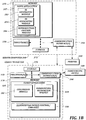
- FIGURE 1B is a block diagram depicting an illustrative server computer 200 and client device 110 in more detail.
- the server computer 200 includes one or more processors 250, one or more communication interfaces 260, and memory 270.
- the form application 205 is loaded into memory 270 from storage 272 and includes an ID generating module 282, an ID associating module 284, and a document reproduction control module 286.
- the ID generating module 282 is the section of the form application 205 responsible for generating information such as field IDs, page IDs, and field types to be stored in the metadata section of document templates and user-specific forms.
- the ID associating module 284 is the section of the form application 205 responsible for associating information such as field IDs, page IDs, and field types with document features such as input areas.
- the document reproduction control module 286 is the section of the form application 205 responsible for reproducing documents (e.g., from a form template) in the form of user-specific forms or printed forms.
- the server computer 200 can transmit user-specific forms and printing information to other devices (such as the client device 110 and the printer 190, respectively) via the communication interface 260.
- the client device 110 includes one or more processors 150, one or more communication interfaces 160, and memory 170.
- a client application 105 is loaded into memory 170 from storage 172 and includes a conversion module 182 and a handwriting association module 184.
- the client device 110 also may include handwriting device control software and related libraries 188 (e.g., signature SDK libraries).
- FIGURE 1C depicts an illustrative handwriting device 100 and its use in a described embodiment.
- the handwriting device 100 includes an EMR sensor 101, a clip 240, and a scanner 241.
- the clip 240 is arranged near the writing surface on the handwriting device 100 to hold a paper 210D in place on the writing surface.
- the paper 210D is reproduced from a first document in the server computer 200, and is printed out by a printer 190.
- the server computer 200 adds a graphically represented ID 230 to a second document when the server computer 200 reproduces the first document.
- the graphically represented ID 230 is associated with a field ID, a location, and a field type.
- the scanner 241 arranged on the handwriting device 100 is configured to scan the graphically represented ID 230 in order to identify, among other potential characteristics, the format of the original document.
- the scanner 241 is included in the clip 240 and positioned to read the graphically represented ID 230 printed on the side of the paper 210D to be signed.
- the scanner 241 can be positioned in the main body of the handwriting device 100 (e.g., below the clip 240).
- FIGURE 1D depicts the paper 210D held in place by the clip 240, with the graphically represented ID 230 located such that it can be scanned by the scanner 241. Having the paper 210D positioned in a known location and orientation allows handwriting input to be accurately applied to the paper such that handwriting input can be associated with the appropriate input area.
- FIGURE 2 is a diagram of an illustrative user-specific form showing handwriting input areas.
- text input areas 220-222 and a checkbox input area 223 are defined.
- Various techniques can be used to assist a user in filling the appropriate input areas in the form. For example, active input areas can be highlighted with a distinctive background color, border, or the like. If certain fields are required to be filled, those fields can be color coded, marked with an asterisk, or distinguished in some other way from fields that are not required. Similarly, fields that have not been filled can be visually distinguished from fields that have been filled.
- Disclosed embodiments can be used with any document file formats that allow inclusion of metadata, such as PDF documents or DOCX documents.
- the document is a PDF document
- an input area within the document can be provided with a matching AcroForm object within the PDF file.
- Extensible Metadata Platform (XMP) packets are used for storing metadata.
- the XMP model is an extension of a Resource Description Framework (RDF) in Extensible Markup Language (XML).
- RDF Resource Description Framework
- XML Extensible Markup Language
- XMP metadata is serialized into XML for storage in files in XMP packets, and is independent of any particular document file format.
- an XMP packet can be embedded in a metadata stream (e.g., of a matching Adobe® Acrobat® form (or AcroForm) object in a PDF document) to store data describing behavior and features of the input area.
- An XMP packet embedded in the metadata stream for the PDF page object can be used to describe or permit generation of features such as a barcode for each individual page.
- An XMP packet embedded in the metadata stream of the root PDF object can store metadata related to the document as a whole, along with other data related to specific portions of the document, such as specific pages or input areas.
- FIGURES 3A-3F depict illustrative metadata in XMP packets that may be included in a metadata section of the document illustrated in FIGURE 2 .
- the XMP packets may be included in a metadata stream of a PDF document.
- some values have been abbreviated or replaced with placeholder values such as XXX.
- document-level metadata elements are contained in an XMP packet, including a page ID ("1234567") for the single page in the document.
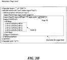
- page-level metadata elements are contained in an XMP packet, including a list of field IDs (e.g., "142532") for the page identified in FIGURE 3A .
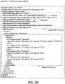
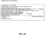
- field-level metadata elements are contained in respective XMP packets for each identified input area 220-223 in FIGURE 2 and corresponding field ID listed in FIGURE 3B .
- the field-level metadata elements may include FieldType (e.g., Text, Number, Freehand, Signature, Boolean), FieldTag (e.g., a user-configurable tag such as "Company Name"), FieldLocation (e.g., x- and y-coordinates and width and height dimensions), Required (indicating whether filling this input area is required for this form), Data, and PenData (stroke data).
- FieldType e.g., Text, Number, Freehand, Signature, Boolean
- FieldTag e.g., a user-configurable tag such as "Company Name”
- FieldLocation e.g., x- and y-coordinates and width and height dimensions
- Required indicating whether filling this input area is required for this form
- Data and PenData (stroke data).
- PenData stroke data
- the value of the Data field depends on the FieldType. For example, if FieldType is "Text" the Data field may reflect the result of applying a handwriting
- the Data field may include encoded pen position data, biometric data, etc., in an encrypted or unencrypted form, along with other information such the signatory's name, reason for signing, or a public key for encryption.
- FIGURES 3C , 3D , and 3E also depict corresponding stroke data, as these input areas have been filled in FIGURE 2 .
- FIGURE 3F lacks stroke data, as the checkbox 223 is empty in FIGURE 2 .
- the checkbox metadata may include a default data value (e.g., "False") to reflect the assumption that if no stroke data is detected in this input area, the user has not checked the box.
- This section provides details of illustrative processes for generating documents with input areas for handwriting input using described file formats, associating handwriting input with input areas in such documents, and related workflows.
- FIGURE 4 is a flow diagram of an illustrative process 400 in which a server computer (e.g., the server computer 200) generates metadata to be stored in a first document when a new PDF file is created or obtained and reproduces a second document with a graphically represented ID, such as a barcode, converted from metadata in the first document.
- the second document can be used for printing a paper version with the graphically represented ID.
- the server computer generates a form ID (e.g., a page ID or a field ID) that identifies a page or input area of a first document.
- the server computer generates a location and a field type for the input area.
- the server computer associates the location and field type with the form ID, and stores the location, field type, and form ID in a metadata stream of the first document.
- the server computer reproduces a second document with a graphically represented ID converted from the form ID of the first document.
- the second document may be printed out by a printer 190 as a paper that may be put onto the handwriting device 100, to be filled in by a user.
- FIGURE 5 is a flow diagram of an illustrative process 500 in which a client device (e.g., the client device 110) associates a positional signal of handwriting with an input area in a document based on metadata elements associated with the document.
- a client device e.g., the client device 110
- the client device obtains a form ID (e.g., a page ID or a field ID) from the handwriting device 100.
- the form ID is obtained from a graphically represented ID, which is scanned by a scanner of a handwriting device (e.g., the scanner 241 of the handwriting device 100).
- the form ID is associated with a location and field type for an input area of the document, and thus the client device can identify the format of the original document (first document) by using the obtained form ID.
- the form ID, location, and field type are stored in a metadata stream of the document.
- the client computing device obtains a positional signal of handwriting from the handwriting device.
- the client computing device associates the positional signal of handwriting with an input area based on the form ID, location, and field type.
- the client device 110 sends a request to a server computer 200 in order to obtain the original PDF file corresponding to the first document.
- the server computer 200 identifies the original PDF file corresponding to the form ID sent from the client device 110 and sends the original PDF file to the client device 110.
- the client device 110 obtains the original PDF file and overlays the positional signal of handwriting onto the original PDF file.
- the client device 110 adds new metadata containing a location and a field type for the input area of the second document in the metadata stream of the original PDF file.
- the client device 110 shows on a display the overlay of handwriting and original form of the PDF file (first document), and the user can check whether or not the handwriting was written properly before sending the document to the server computer 200. Since the client device 110 adds the metadata, including handwriting data, in the metadata stream of the original PDF file as well as overlaying the handwriting on the original PDF file, the handwriting data can be put onto the server computer 200 automatically. This may help to reduce the need for manual input by the user of information corresponding to the handwriting data. More preferably, the client device 110 can convert the positional signal of handwriting according to a location and a field type for the input area corresponding to the original document which has the same form ID. The invention is not limited to this embodiment, however; for example, the server computer 200, instead of the client device 110, may convert the positional signal of handwriting according to a location and a field type for the input area corresponding to the original document which has the same form ID.
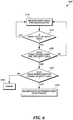
- FIGURE 6 is a flow diagram of an illustrative process 600 to determine whether point data in a positional signal (pen data) is to be associated with an input area.
- the input area has a margin (or bleed area) that is considered to be part of the input area.
- a computing device e.g., client device 110
- receives point data for handwriting At step 610, the computing device determines whether the point data is in the input area. If it is, the next point is processed. If it is not, the computing device makes a further determination at step 630 as to whether the point exceeds the margin for the input area. If it does not, the next point is processed.
- the computing device makes a further determination at step 640 as to whether the first down point (e.g., with pressure value greater than 0) of the stroke was within the input area. If it was, the point is incorporated into the stroke associated with the input area at step 650. If it was not, the process returns an error at step 660.
- the first down point e.g., with pressure value greater than 0
- this pen data can still be preserved in metadata, even if it is not associated with an input area.
- Such pen data can be analyzed later to determine the intent of the signer. This may be helpful, for example, where paper moves during signing, or where users write in unexpected areas of a document.
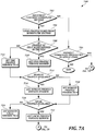
- FIGURES 7A-7B describe a further workflow process 700 that can be used in combination with embodiments described herein.
- the workflow process 700 mainly deals with how software should load a workstep profile for a document if the document workflow step options are enabled.
- a workstep profile is a workflow that the client or server performs when a document arrives into its domain (e.g., when the file is pushed to the client).
- the workflow can be used when a document needs to be signed by User 1, and then emailed to User 2 for countersigning before being uploaded to a website.
- a pre-completion section of the workflow deals with issues to be conveyed before the document is processed; an example of this would be an option that the client should browse to the next active area immediately when the document is received.
- the pre-completion section also contains details of the current step within the workflow that is the active step in the case of a document that has multiple stages.
- the pre-completion section also includes the details on the criteria that the document should meet for the current workflow step to be completed (e.g., Field ID xxxx and Field ID yyyy must be completed, after which the post-completion rule for the current workflow step can be executed).
- the post-completion section deals with what happens to the document after the current workflow step is considered completed. This may be, for example, saving the document with a particular specified name format, and outputting the document (e.g., file upload, e-mail, or some other mechanism).
- the post-completion processing by the client software will also increment the current work step number in the work flow rule to indicate the state the document is currently in.
- workflow profiles can be stored as an extension within the document level of the file format.
- client software can support the concept of a profile, such as a default profile or a named profile, rather than having the workflow explicitly defined within every file. This allows the flexibility for documents without workflows to have a workflow applied, or for documents with existing, but out of date workflow definitions to be updated without having to edit the original document.
- Client software also can configure a default profile from its local cache or remotely to apply to documents that do not have a profile.
- a computing device determines whether a document contains a workflow section. If it does, a profile name is loaded at step 704. If it does not, a check for a default profile is made at step 706. If the profile name is loaded at step 704, a check is made at step 708 is made whether a profile of that name is in the file. If it is, the profile version number is obtained at step 710. If it is not, the profile version is set to 0 at step 712. At step 714, a check for a remote profile is performed. If a remote profile is available, the version number is obtained at step 716.
- the remote profile version is set to 0 at step 718.
- a check for a local profile is performed. If a local profile is available, the version number is obtained at step 722. If no local profile is available, the local profile version is set to 0 at step 724.
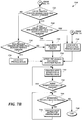
- step 726 if the local profile version is higher than the file profile version (step 726), a further check is performed to determine whether the local profile version is higher than the remote profile version at step 728. If it is, the local application profile rules are loaded at step 730. If not, the remote profile rules are loaded at step 732. If the local profile version is not higher than the file profile version, a further check is performed to determine whether the file profile version is higher than the remote profile version at step 734. If is not, the process returns to step 732. If it is, file profile rules are loaded at step 736.
- step 738 When the selected profile rules are loaded, global document behavior is set up at step 738. A workstep is processed in the profile rule at step 740. If more worksteps remain (step 742), the next workstep is processed. If not, the process proceeds to output rules at step 744. If any output rules remain, the next output rule is processed at step 746. If not, the process ends at step 750.
- Embodiments described herein can be implemented by suitably programmed and configured computing devices, individually or in combination.
- the description below is applicable to computing devices such as servers, personal computers, mobile phones, smart phones, tablet computers, embedded computing devices, handwriting devices, and other currently available or yet to be developed devices that may be used in accordance with embodiments of the present disclosure.
- a computing device includes at least one processor and a system memory connected by a communication bus.
- the system memory may be volatile or nonvolatile memory, such as read only memory (“ROM”), random access memory (“RAM”), EEPROM, flash memory, or other memory technology.
- ROM read only memory
- RAM random access memory
- EEPROM electrically erasable programmable read-only memory
- flash memory or other memory technology.
- system memory typically stores data and/or program modules that are immediately accessible to and/or currently being operated on by the processor.
- the processor may serve as a computational center of the computing device by supporting the execution of instructions.
- the computing device may include a network interface comprising one or more components for communicating with other devices over a network.
- Embodiments of the present disclosure may access basic services that utilize a network interface to perform communications using common network protocols.
- the network interface may also include a wireless network interface configured to communicate via one or more wireless communication protocols, such as WiFi, 2G, 3G, 4G, LTE, WiMAX, Bluetooth, and/or the like.
- the computing device also may include a storage medium.
- services may be accessed using a computing device that does not include means for persisting data to a local storage medium. Therefore, the storage medium is optional.
- the storage medium may be volatile or nonvolatile, removable or non-removable, implemented using any technology capable of storing information such as, but not limited to, a hard drive, solid state drive, CD-ROM, DVD, or other disk storage, magnetic tape, magnetic disk storage, and/or the like.
- computer readable medium includes volatile and nonvolatile and removable and non-removable media implemented in any method or technology capable of storing information, such as computer readable instructions, data structures, program modules, or other data.
- system memory and storage media are examples of computer readable media.
- a computing device may include input devices, such as a keyboard, keypad, mouse, trackball, microphone, video camera, touchpad, touchscreen, stylus, and/or the like.
- input devices may be coupled to the computing device by wired or wireless connections including RF, infrared, serial, parallel, Bluetooth, USB, or other suitable connection protocols using wireless or physical connections.
- data can be captured by input devices (e.g., signature devices) and transmitted or stored for future processing.
- the processing may include encoding data, which can be subsequently decoded for presentation by output devices.
- Input devices can be separate from and communicatively coupled to a computing device, or can be integral components of the computing device.
- the computing device may also include output devices such as a display or touchscreen.
- the output devices can be separate from and communicatively coupled to the computing device, or can be integral components of the computing device.
- Input functionality and output functionality may be integrated into the same input/output device (e.g., a touchscreen). Any suitable input device, output device, or combined input/output device either currently known or developed in the future may be used with described systems.
- functionality of computing devices described herein may be implemented in computing logic embodied in hardware or software instructions, which can be written in a programming language, such as C, C++, COBOL, JAVATM, PHP, Perl, Python, Ruby, HTML, CSS, JavaScript, VBScript, ASPX, Microsoft NETTM languages such as C#, and/or the like.
- Computing logic may be compiled into executable programs or written in interpreted programming languages.
- functionality described herein can be implemented as logic modules that can be duplicated to provide greater processing capability, merged with other modules, or divided into sub modules.
- the computing logic can be stored in any type of computer readable medium (e.g., a non-transitory medium such as a memory or storage medium) or computer storage device and be stored on and executed by one or more general purpose or special purpose processors, thus creating a special purpose computing device configured to provide functionality described herein.
- a computer readable medium e.g., a non-transitory medium such as a memory or storage medium
- computer storage device e.g., a non-transitory medium such as a memory or storage medium
- modules or subsystems can be separated into additional modules or subsystems or combined into fewer modules or subsystems.
- modules or subsystems can be omitted or supplemented with other modules or subsystems.
- functions that are indicated as being performed by a particular device, module, or subsystem may instead be performed by one or more other devices, modules, or subsystems.
- processing stages in the various techniques can be separated into additional stages or combined into fewer stages.
- processing stages in the various techniques can be omitted or supplemented with other techniques or processing stages.
- processing stages that are described as occurring in a particular order can instead occur in a different order.
- processing stages that are described as being performed in a series of steps may instead be handled in a parallel fashion, with multiple modules or software processes concurrently handling one or more of the illustrated processing stages.
- processing stages that are indicated as being performed by a particular device or module may instead be performed by one or more other devices or modules.
Description
- This application claims the benefit of Provisional Application No.
62/382765, filed September 1, 2016 - Electronic handwriting is increasingly important and popular in a variety of contexts, such as electronic signatures for documents. Many devices can be used for electronic handwriting. One technique that is gaining in popularity is using an electronic stylus to add handwriting to an electronic document. For example, a user may view a document on a tablet device while writing with the electronic stylus, thereby allowing the user to accurately place handwriting in the electronic document, such as by signing the user's name on a signature line. Yet, writing in ink on paper also remains important in many contexts. In one possible scenario, an electronic stylus with an ink cartridge can be used to generate electronic handwriting data while also applying ink to paper. Although electronic handwriting can be captured during this type of writing process, a typical electronic handwriting device has no ability to process or interpret the handwriting data intelligently with respect to a specific document that is being signed.
-
US 2006/0007189 A1 describes a forms-based computer interface which captures and interprets handwriting, pen movements, and other manual graphical-type user input for use in computerized applications and databases. A portable Input and Control Device, a writing implement, and a host computing device are utilized that together capture, interpret, utilize, and store the handwriting, marks, and other pen movements of a user on and around predefined and identified forms. Form, field, and user-specific handwriting and mark recognition are used in the interpretation of user input. An edit utility permits review and editing of the captured and interpreted input, permitting correction of capture and interpretation errors. - This summary is provided to introduce a selection of concepts in a simplified form that are further described below in the Detailed Description. This summary is not intended to identify key features of the claimed subject matter, nor is it intended to be used as an aid in determining the scope of the claimed subject matter.
- In one aspect, a computer-implemented method comprises generating a form identifier to identify a page or an input area of a first document; generating a location and a field type for the input area of the first document; associating the location and the field type with the form identifier, wherein the location, the field type, and the form identifier are stored in a metadata stream of the first document; and reproducing a second document from the first document with a graphically represented identifier converted from the form identifier. The first document may include a plurality of input areas, and the plurality of input areas may comprise multiple types of input areas. The multiple types of input areas may include a signature area. The form identifier and the location and the field type may be stored in the metadata stream of the first document in a structured document format. The structured document format may include a root element and a plurality of sub-elements that are nested within the root element. The form identifier, the location, and the field type may be stored in the sub-elements. The form identifier may be stored in an attribute property of one of the sub-elements. The structured document format may be an XML format. The metadata stream of the document may be in a metadata format that is independent of file format of the document. The metadata format may be an XMP format. The graphically represented identifier may be selected from the group consisting of a barcode, a dot code, and a QR code. The method may further include generating dimensions for the input area of the first document.
- In another aspect, a computer-implemented method executed by a computer that is electrically connected with a handwriting device comprises obtaining a form identifier converted from a graphically represented identifier of a document from the handwriting device, wherein the form identifier is associated with a location and a field type for an input area of the document, and wherein the form identifier, the location, and the field type are stored in a metadata stream of the document; obtaining a positional signal of handwriting from the handwriting device; and associating the positional signal of the handwriting with the input area based on the form identifier, the location, and the field type. The method may include converting the handwriting into a data type based at least in part on the field type for the input area. The handwriting may include pen coordinate data. The handwriting also may include biometric data. The metadata may be stored in the metadata stream in an XMP format. The metadata stream of the document may include dimensions for the input area of the document. The positional signal may include a series of point locations. Associating the positional signal of the handwriting with the input area may include determining whether the point locations are within the input area. Associating the positional signal of the handwriting with the input area also may include determining whether the point locations are within a bleed margin of the input area. Associating the positional signal of the handwriting with the input area also may include determining whether a first down point of a stroke is within the input area.
- In another aspect, a system includes a computing device programmed to generate a form identifier to identify a page or an input area of a first document; generate a location and a field type for the input area of the first document; associate the location and the field type with the form identifier, wherein the location, the field type, and the form identifier are stored in a metadata stream of the first document; and reproduce a second document from the first document with a graphically represented identifier converted from the form identifier. The system also includes a handwriting device and a client computing device programmed to obtain a form identifier converted from the graphically represented identifier of the second document from the handwriting device, wherein the form identifier is associated with the location and the field type for the input area of the second document, and wherein the form identifier, the location, and the field type are stored in a metadata stream of the second document; obtain a positional signal of handwriting from the handwriting device; and associate the positional signal of the handwriting with the input area based on the form identifier, the location, and the field type.
- A computing device may be programmed to perform any of the techniques described above or elsewhere herein. A computer-readable medium may have stored thereon executable instructions configured to cause a computing device to perform any of the techniques described above or elsewhere herein.
- The foregoing aspects and many of the attendant advantages will become more readily appreciated as the same become better understood by reference to the following detailed description, when taken in conjunction with the accompanying drawings, wherein:
-
FIGURES 1A-1D are block diagrams of illustrative systems and devices in which described embodiments may be implemented; -
FIGURE 2 is a diagram of an illustrative user-specific form showing handwriting input areas; -
FIGURES 3A-3F are code diagrams that depict illustrative metadata in XMP packets that may be included in a metadata section of the document illustrated inFIGURE 2 ; -
FIGURE 4 is a flow diagram of an illustrative process in which a server computer generates metadata to be stored in a first document and reproduces a second document with a graphically represented ID converted from metadata in the first document; -
FIGURE 5 is a flow diagram of an illustrative process in which a client device associates a positional signal of handwriting with an input area in a document based on metadata elements associated with the document; -
FIGURE 6 is a flow diagram of an illustrative process to determine whether point data in a positional signal (pen data) is to be associated with an input area; and -
FIGURES 7A and7B are flow diagrams that describe a workflow process involving profiles for processing of electronic documents described herein. - In embodiments described herein, input areas of a document are defined (e.g., in terms of location, dimensions, and type) in metadata within the document. Specific items of metadata that may be used in described embodiments include tags, text, identifiers (IDs), and Boolean values. The metadata provides the ability to store data describing behavior and features of the input areas within the document file itself. Embodiments described herein are particularly useful for handwriting input. When input (such as handwriting input) is applied to a document, the input data (e.g., captured stroke data corresponding to handwriting input) can be stored within the document along with other metadata. Input applied to a particular input area can be associated with the input area. The workflow in described embodiments can be conceived as involving two stages: form creation, which includes defining input areas, and data capture, which includes receiving and processing input, such as handwriting input received from a handwriting device and a graphically represented ID on a paper, in a corresponding document.
- In one embodiment, a disclosed file format is used in combination with a handwriting device, such as a smart folio or tablet device, and an associated pen device. The pen device is designed for writing in ink on paper while also generating corresponding electronic handwriting data during the writing process that can be mapped to particular input areas in the document. For example, a client application running on a client device in communication with the handwriting device can embed electronic handwriting data in electronic documents as ink handwriting is applied to corresponding paper documents, and can associate the electronic handwriting data with an input area.
- As used herein, the term "handwriting device" refers to a hybrid device that captures handwriting input digitally using a stylus pen while the user writes with the pen on paper. Handwriting devices may be implemented as dedicated handwriting collection devices, such as handwriting pad devices or handwriting tablet devices. Handwriting devices are not necessarily strictly input devices, and may include other functionality (e.g., data transmission functionality, etc.). Further details on illustrative handwriting devices are provided below.
- Described embodiments allow automatic creation of electronic documents that include classes of data that are not available from paper documents or scanned images of paper documents, such as biometric data (e.g., pen pressure data, timing/velocity of strokes) and pen position data. Such data can be used for signature authentication, automatic character recognition or shape recognition, or other interpretation of handwriting (such as identifying marks in checkboxes) in particular input areas, or for other purposes. Described embodiments can avoid time-consuming intervening steps such as optical character recognition or human inspection of handwritten forms, though such steps could optionally be used to supplement or cross-check results of automatic techniques. Electronic versions of the paper documents can then be stored locally or transmitted to another device for storage or further processing, such as in a cloud computing arrangement. In addition to storing handwriting data as metadata, described systems and devices also can store an image of the signed document or images of particular handwriting along with the document.
-
FIGURE 1A is a block diagram of an illustrative system in which described embodiments may be implemented. In the example shown inFIGURE 1A , ahandwriting device 100 communicates with a client device 110 (e.g., via USB, Bluetooth, or other suitable connection). Theclient device 110 also communicates with aserver computer 200 running aform application 205. (Server computer 200 andclient device 110 are described in further detail below with reference toFIGURE 1B .) AlthoughFIGURE 1A shows a single server computer, client device, and handwriting device for ease of illustration, it should be understood, in the context of this example and other examples described herein, that one or more additional handwriting devices, client devices, and server computers may be present. In such scenarios, many arrangements and topologies are possible. For example, a client device may communicate with more than one handwriting device and a server computer may communicate with more than one client device. A client device can be a desktop or notebook computer, a smartphone, a tablet device, or some other computing device. - In the illustrative scenario depicted in
FIGURE 1A , aform application 205 running on theserver computer 200 generates a form from asource document 210A (e.g., a document in a PDF format or other electronic document format) andform information 212 provided as input to theform application 205. Theform information 212 indicates information (e.g., position, dimensions, name, type) associated with input areas (e.g., handwriting input areas) for the form. The source document 210A provides document data for the form, and may also include basic metadata for the form such as creation time/date, author, etc. The document data may include text, graphics, formatting information, and other information that represents the content of the document when it is displayed or printed. - In the illustrative scenario depicted in
FIGURE 1A , theform application 205 generates aform template 210B, from which individual documents (e.g., a user-specific form 210C) can be generated. Theform template 210B includes a document data section and a metadata section. The metadata section includes additional information for the document. Theform application 205 uses theform information 212 to identify and define an input area 220 (e.g., a handwriting input area) in theform template 210B. Theform application 205 associates theinput area 220 with metadata in the metadata section of theform template 210B. In this example, theinput area 220 is associated with a field ID, a location, and a field type. Other metadata that may be included in theform template 210B (e.g., a document ID, page IDs, creation time/date, author, etc.) is not shown for ease of illustration. - In the illustrative scenario depicted in
FIGURE 1A , theform application 205 generates a user-specific form 210C based on theform template 210B and other information specific to a particular user (e.g., a hospital patient filling in an admission form, a bank customer signing an agreement) that will be adding handwriting to the form. In doing so, theform application 205 generates a graphically represented ID 230 (e.g., barcode, dot code, QR code) to be included in the user-specific form 210C. The graphically representedID 230 can be read and decoded (e.g., by a suitably configured scanner orcamera device 241 arranged on a handwriting device 100) to obtain information about the document for subsequent processing. The user-specific form 210C also includes metadata from the form template, including the field ID, location, and field type associated with theinput area 220. Theserver computer 200 transmits the user-specific form 210C to theclient device 110, which transmits the user-specific form 210C in electronic form to thehandwriting device 100. - In one embodiment, the
form application 205 generates the graphically representedID 230 by converting one or more IDs stored in the metadata section of the document into a corresponding code. The IDs to be converted may include IDs associated with the document itself (e.g., document ID, page ID, field ID), IDs associated with a user, or some combination of IDs. At the client side, the graphically representedID 230 can be decoded to obtain the information that was used to generate the graphically representedID 230. Information obtained in this way can then be used to map handwriting data to particular input areas in the document. If the position signals of the handwriting data match with the defined input areas, the client device can associate the handwriting data with those input areas and store the handwriting data and the association in the metadata section of the electronic document. - For example, a numeric code of the form [DocID][PageID] can be converted into a barcode and added to a document to be signed by a user. When the barcode is read and decoded by a scanner 241 (e.g., prior to a user signing the document), the document ID and page ID can be used by the
client device 110 to look up the corresponding electronic document and page and identify defined input areas on that page. To accomplish this, the code is sufficiently unique such that the appropriate document and location can be accurately identified. The level of uniqueness can be varied based on factors such as the overall number of documents and pages that are expected to be handled in a particular implementation. Universally unique identifiers (UUIDs) may be preferred in some circumstances but are not required for this purpose. - In the illustrative scenario depicted in
FIGURE 1A , thehandwriting device 100 is a smart folio or smart clipboard device designed for use with apen device 102 capable of generating electronic handwriting data as well as writing in ink (which may be stored in a replaceable ink cartridge) on paper. Therefore, in this example, theserver computer 200 transmits printing information for the user-specific form 210C to aprinter 190 that produces a printedform 210D (including the graphically represented ID 230). - Referring again to
FIGURE 1A , thehandwriting device 100 may include one or more visual or mechanical guides (not shown) to aid in placing the paper in an appropriate location on thehandwriting device 100, and may also include aclip 240 to hold and maintain the position of thepaper 210D on thehandwriting device 100 during the writing process, and ascanner 241 to scan the graphically representedID 230 printed on thepaper 210D. With thepaper 210D being positioned and held in an expected location, thehandwriting device 100 is able to provide handwriting position data to theclient device 110 such that it can be accurately mapped to a corresponding position in the electronic document. - Handwriting data received by the
client device 110 from thehandwriting device 100 typically includes pen event data (e.g., coordinate data and pressure data) and may also include other data, such as an image of a signature, biometric data, etc. One or more sensor modules that generate sensor data may be included in thehandwriting device 100 or, in some cases, in other devices, such as thepen 102. The sensor data can be translated into pen event data, such as position/coordinate data and pressure data. - In this example, the
handwriting device 100 andpen device 102 use electromagnetic resonance (EMR) technology to generate handwriting data, but thehandwriting device 100 can be a capacitive stylus or other type of stylus. AnEMR sensor 101 in thehandwriting device 100 is implemented as a digitizer that incorporates a sensor board that detects the pen's movement, and energy is induced in the pen's resonant circuit by a magnetic field generated by the sensor board surface. The pen's resonant circuit then makes use of this energy to return a magnetic signal to the sensor board surface. The board detects the pen's coordinate position at regular time intervals even if the electronic pen does not touch the sensor board surface, so long as the pen remains within close enough proximity to the sensor board, such that signals can still be received from the pen. (The effective signal range can vary depending on the particular technology being used, but is generally on the order of several millimeters.) - Alternatively, other handwriting input technology can be used. For example, an electronic pen may use other wireless technology or may be connected by a wire to a digitizer. As another example, an electronic pen may or may not be detectable away from the surface of a digitizer. As another example, an electronic pen may be powered or unpowered. Powered pens may receive power via a wire connected to an external power source or via an on-board battery. As another example, it is possible to input handwriting data without an electronic pen (e.g., via a stylus on a pressure sensitive digital writing pad, a touchscreen, or some other input device that does not require an electronic pen).
- However the handwriting data may be collected, handwriting data provided by signature devices may include pen event information, device information, and/or contextual information about the context in which the handwriting was made. Pen event information may include the x/y position of the pen-tip on or above the digitizer surface and the time since the start of the handwriting. In addition to x/y-coordinate values, pen event information may optionally include additional information subject to the capabilities of the signature device, such as pressure (pen force), angles (azimuth, altitude, and/or rotation) and pen-down status. Pen event information is typically collected at regular intervals during a signing process. The sampling rates at which pen event information may be collected may vary depending on system design and configuration.
- Handwriting data can be stored in a raw or compressed format. Handwriting data, document data, or metadata may encrypted or unencrypted, depending on factors such as desired levels of security or sensitivity of particular applications.
-
FIGURE 1B is a block diagram depicting anillustrative server computer 200 andclient device 110 in more detail. In the example shown inFIGURE 1B , theserver computer 200 includes one ormore processors 250, one ormore communication interfaces 260, andmemory 270. Theform application 205 is loaded intomemory 270 fromstorage 272 and includes anID generating module 282, anID associating module 284, and a documentreproduction control module 286. - In this example, the
ID generating module 282 is the section of theform application 205 responsible for generating information such as field IDs, page IDs, and field types to be stored in the metadata section of document templates and user-specific forms. TheID associating module 284 is the section of theform application 205 responsible for associating information such as field IDs, page IDs, and field types with document features such as input areas. The documentreproduction control module 286 is the section of theform application 205 responsible for reproducing documents (e.g., from a form template) in the form of user-specific forms or printed forms. Theserver computer 200 can transmit user-specific forms and printing information to other devices (such as theclient device 110 and theprinter 190, respectively) via thecommunication interface 260. - In the example shown in
FIGURE 1B , theclient device 110 includes one ormore processors 150, one ormore communication interfaces 160, andmemory 170. Aclient application 105 is loaded intomemory 170 fromstorage 172 and includes aconversion module 182 and ahandwriting association module 184. For handwriting device control and related data processing, theclient device 110 also may include handwriting device control software and related libraries 188 (e.g., signature SDK libraries). -
FIGURE 1C depicts anillustrative handwriting device 100 and its use in a described embodiment. In the example shown inFIGURE 1C , thehandwriting device 100 includes anEMR sensor 101, aclip 240, and ascanner 241. Theclip 240 is arranged near the writing surface on thehandwriting device 100 to hold apaper 210D in place on the writing surface. Referring again toFIGURE 1A , in an illustrative scenario thepaper 210D is reproduced from a first document in theserver computer 200, and is printed out by aprinter 190. Theserver computer 200 adds a graphically representedID 230 to a second document when theserver computer 200 reproduces the first document. The graphically representedID 230 is associated with a field ID, a location, and a field type. - Turning again to
FIGURE 1C , thescanner 241 arranged on thehandwriting device 100 is configured to scan the graphically representedID 230 in order to identify, among other potential characteristics, the format of the original document. In the example shown inFIGURE 1C , thescanner 241 is included in theclip 240 and positioned to read the graphically representedID 230 printed on the side of thepaper 210D to be signed. Alternatively, such as where the graphically representedID 230 may be printed on the reverse side of thepaper 210D, thescanner 241 can be positioned in the main body of the handwriting device 100 (e.g., below the clip 240).FIGURE 1D depicts thepaper 210D held in place by theclip 240, with the graphically representedID 230 located such that it can be scanned by thescanner 241. Having thepaper 210D positioned in a known location and orientation allows handwriting input to be accurately applied to the paper such that handwriting input can be associated with the appropriate input area. -
FIGURE 2 is a diagram of an illustrative user-specific form showing handwriting input areas. In the example shown inFIGURE 2 , text input areas 220-222 and acheckbox input area 223 are defined. Various techniques can be used to assist a user in filling the appropriate input areas in the form. For example, active input areas can be highlighted with a distinctive background color, border, or the like. If certain fields are required to be filled, those fields can be color coded, marked with an asterisk, or distinguished in some other way from fields that are not required. Similarly, fields that have not been filled can be visually distinguished from fields that have been filled. - Disclosed embodiments can be used with any document file formats that allow inclusion of metadata, such as PDF documents or DOCX documents. For example, if the document is a PDF document, an input area within the document can be provided with a matching AcroForm object within the PDF file. In at least one embodiment, Extensible Metadata Platform (XMP) packets are used for storing metadata. The XMP model is an extension of a Resource Description Framework (RDF) in Extensible Markup Language (XML). XMP metadata is serialized into XML for storage in files in XMP packets, and is independent of any particular document file format. (See "XMP Specification Part 3: Storage in Files" (July 2010), available from Adobe Systems Inc.) In an illustrative scenario, an XMP packet can be embedded in a metadata stream (e.g., of a matching Adobe® Acrobat® form (or AcroForm) object in a PDF document) to store data describing behavior and features of the input area. An XMP packet embedded in the metadata stream for the PDF page object can be used to describe or permit generation of features such as a barcode for each individual page. An XMP packet embedded in the metadata stream of the root PDF object can store metadata related to the document as a whole, along with other data related to specific portions of the document, such as specific pages or input areas.
-
FIGURES 3A-3F depict illustrative metadata in XMP packets that may be included in a metadata section of the document illustrated inFIGURE 2 . For example, the XMP packets may be included in a metadata stream of a PDF document. (To simplify the presentation of the metadata in these figures, some values have been abbreviated or replaced with placeholder values such as XXX.) - In the example shown in
FIGURE 3A , document-level metadata elements are contained in an XMP packet, including a page ID ("1234567") for the single page in the document. In the example shown inFIGURE 3B , page-level metadata elements are contained in an XMP packet, including a list of field IDs (e.g., "142532") for the page identified inFIGURE 3A . In the examples shown inFIGURES 3C-3F , field-level metadata elements are contained in respective XMP packets for each identified input area 220-223 inFIGURE 2 and corresponding field ID listed inFIGURE 3B . The field-level metadata elements may include FieldType (e.g., Text, Number, Freehand, Signature, Boolean), FieldTag (e.g., a user-configurable tag such as "Company Name"), FieldLocation (e.g., x- and y-coordinates and width and height dimensions), Required (indicating whether filling this input area is required for this form), Data, and PenData (stroke data). The value of the Data field depends on the FieldType. For example, if FieldType is "Text" the Data field may reflect the result of applying a handwriting recognition algorithm to the handwriting input. As another example, if Field Type is "Signature" the Data field may include encoded pen position data, biometric data, etc., in an encrypted or unencrypted form, along with other information such the signatory's name, reason for signing, or a public key for encryption. - In these examples,
FIGURE 3C depicts metadata for the "Name" box (FieldType=Text) ("220" inFIGURE 2 ),FIGURE 3D depicts metadata for the "Company Name" box (FieldType=Text) ("221" inFIGURE 2 ),FIGURE 3E depicts metadata for the "Date" box (FieldType=Text) ("222" inFIGURE 2 ), andFIGURE 3F depicts metadata for the checkbox (FieldType=Boolean) ("223" inFIGURE 2 ).FIGURES 3C ,3D , and3E also depict corresponding stroke data, as these input areas have been filled inFIGURE 2 . (For ease of presentation, the pen data is abbreviated to a single stroke inFIGURES 3C ,3D , and3E . In practice, a line of printed characters such as those shown in the "Name" or "Company Name" box would consist of a much larger number of strokes.)FIGURE 3F lacks stroke data, as thecheckbox 223 is empty inFIGURE 2 . Though not shown inFIGURE 3F , the checkbox metadata may include a default data value (e.g., "False") to reflect the assumption that if no stroke data is detected in this input area, the user has not checked the box. - This section provides details of illustrative processes for generating documents with input areas for handwriting input using described file formats, associating handwriting input with input areas in such documents, and related workflows.
-
FIGURE 4 is a flow diagram of anillustrative process 400 in which a server computer (e.g., the server computer 200) generates metadata to be stored in a first document when a new PDF file is created or obtained and reproduces a second document with a graphically represented ID, such as a barcode, converted from metadata in the first document. The second document can be used for printing a paper version with the graphically represented ID. In the example shown inFIGURE 4 , atstep 410 the server computer generates a form ID (e.g., a page ID or a field ID) that identifies a page or input area of a first document. Atstep 420, the server computer generates a location and a field type for the input area. Atstep 430, the server computer associates the location and field type with the form ID, and stores the location, field type, and form ID in a metadata stream of the first document. Atstep 440, the server computer reproduces a second document with a graphically represented ID converted from the form ID of the first document. Referring again toFIGURE 1A , the second document may be printed out by aprinter 190 as a paper that may be put onto thehandwriting device 100, to be filled in by a user. -
FIGURE 5 is a flow diagram of anillustrative process 500 in which a client device (e.g., the client device 110) associates a positional signal of handwriting with an input area in a document based on metadata elements associated with the document. In the example shown inFIGURE 5 , atstep 510 the client device obtains a form ID (e.g., a page ID or a field ID) from thehandwriting device 100. In at least one embodiment, the form ID is obtained from a graphically represented ID, which is scanned by a scanner of a handwriting device (e.g., thescanner 241 of the handwriting device 100). The form ID is associated with a location and field type for an input area of the document, and thus the client device can identify the format of the original document (first document) by using the obtained form ID. The form ID, location, and field type are stored in a metadata stream of the document. Atstep 520, the client computing device obtains a positional signal of handwriting from the handwriting device. Atstep 530, the client computing device associates the positional signal of handwriting with an input area based on the form ID, location, and field type. - An example of additional workflow that may be performed in accordance with one or more embodiments will now be described. In this example, the
client device 110 sends a request to aserver computer 200 in order to obtain the original PDF file corresponding to the first document. Theserver computer 200 identifies the original PDF file corresponding to the form ID sent from theclient device 110 and sends the original PDF file to theclient device 110. Theclient device 110 obtains the original PDF file and overlays the positional signal of handwriting onto the original PDF file. In addition, theclient device 110 adds new metadata containing a location and a field type for the input area of the second document in the metadata stream of the original PDF file. Theclient device 110 shows on a display the overlay of handwriting and original form of the PDF file (first document), and the user can check whether or not the handwriting was written properly before sending the document to theserver computer 200. Since theclient device 110 adds the metadata, including handwriting data, in the metadata stream of the original PDF file as well as overlaying the handwriting on the original PDF file, the handwriting data can be put onto theserver computer 200 automatically. This may help to reduce the need for manual input by the user of information corresponding to the handwriting data. More preferably, theclient device 110 can convert the positional signal of handwriting according to a location and a field type for the input area corresponding to the original document which has the same form ID. The invention is not limited to this embodiment, however; for example, theserver computer 200, instead of theclient device 110, may convert the positional signal of handwriting according to a location and a field type for the input area corresponding to the original document which has the same form ID. -
FIGURE 6 is a flow diagram of anillustrative process 600 to determine whether point data in a positional signal (pen data) is to be associated with an input area. In this example, the input area has a margin (or bleed area) that is considered to be part of the input area. Atstep 610, a computing device (e.g., client device 110) receives point data for handwriting. Atstep 620, the computing device determines whether the point data is in the input area. If it is, the next point is processed. If it is not, the computing device makes a further determination atstep 630 as to whether the point exceeds the margin for the input area. If it does not, the next point is processed. If it does, the computing device makes a further determination atstep 640 as to whether the first down point (e.g., with pressure value greater than 0) of the stroke was within the input area. If it was, the point is incorporated into the stroke associated with the input area atstep 650. If it was not, the process returns an error atstep 660. - If an error is returned due to pen data being outside of an input area, this pen data can still be preserved in metadata, even if it is not associated with an input area. Such pen data can be analyzed later to determine the intent of the signer. This may be helpful, for example, where paper moves during signing, or where users write in unexpected areas of a document.
-
FIGURES 7A-7B describe afurther workflow process 700 that can be used in combination with embodiments described herein. Theworkflow process 700 mainly deals with how software should load a workstep profile for a document if the document workflow step options are enabled. In this illustrative example, a workstep profile is a workflow that the client or server performs when a document arrives into its domain (e.g., when the file is pushed to the client). In an illustrative scenario, the workflow can be used when a document needs to be signed byUser 1, and then emailed to User 2 for countersigning before being uploaded to a website. - In one embodiment, a pre-completion section of the workflow deals with issues to be conveyed before the document is processed; an example of this would be an option that the client should browse to the next active area immediately when the document is received. The pre-completion section also contains details of the current step within the workflow that is the active step in the case of a document that has multiple stages. The pre-completion section also includes the details on the criteria that the document should meet for the current workflow step to be completed (e.g., Field ID xxxx and Field ID yyyy must be completed, after which the post-completion rule for the current workflow step can be executed).
- The post-completion section deals with what happens to the document after the current workflow step is considered completed. This may be, for example, saving the document with a particular specified name format, and outputting the document (e.g., file upload, e-mail, or some other mechanism). The post-completion processing by the client software will also increment the current work step number in the work flow rule to indicate the state the document is currently in.
- These workflow profiles can be stored as an extension within the document level of the file format. However, it is also possible for client software to support the concept of a profile, such as a default profile or a named profile, rather than having the workflow explicitly defined within every file. This allows the flexibility for documents without workflows to have a workflow applied, or for documents with existing, but out of date workflow definitions to be updated without having to edit the original document.
- Thus, there are several options for defining a workflow in a document:
- Explicitly within document level metadata (e.g., XMP).
- As a named profile in the metadata that is loaded from the client cache.
- As a remote profile in the metadata that is downloaded to a client dynamically and applied.
- Client software also can configure a default profile from its local cache or remotely to apply to documents that do not have a profile.
- In this illustrative context, the example depicted in
FIGURES 7A and7B can now be described. Turning first toFIGURE 7A , atstep 702, a computing device determines whether a document contains a workflow section. If it does, a profile name is loaded atstep 704. If it does not, a check for a default profile is made atstep 706. If the profile name is loaded atstep 704, a check is made atstep 708 is made whether a profile of that name is in the file. If it is, the profile version number is obtained atstep 710. If it is not, the profile version is set to 0 atstep 712. Atstep 714, a check for a remote profile is performed. If a remote profile is available, the version number is obtained atstep 716. If no remote profile is available, the remote profile version is set to 0 atstep 718. Atstep 720, a check for a local profile is performed. If a local profile is available, the version number is obtained atstep 722. If no local profile is available, the local profile version is set to 0 atstep 724. - Turning now to
FIGURE 7B , if the local profile version is higher than the file profile version (step 726), a further check is performed to determine whether the local profile version is higher than the remote profile version atstep 728. If it is, the local application profile rules are loaded atstep 730. If not, the remote profile rules are loaded atstep 732. If the local profile version is not higher than the file profile version, a further check is performed to determine whether the file profile version is higher than the remote profile version atstep 734. If is not, the process returns to step 732. If it is, file profile rules are loaded atstep 736. - When the selected profile rules are loaded, global document behavior is set up at
step 738. A workstep is processed in the profile rule atstep 740. If more worksteps remain (step 742), the next workstep is processed. If not, the process proceeds to output rules atstep 744. If any output rules remain, the next output rule is processed atstep 746. If not, the process ends atstep 750. - Embodiments described herein can be implemented by suitably programmed and configured computing devices, individually or in combination. The description below is applicable to computing devices such as servers, personal computers, mobile phones, smart phones, tablet computers, embedded computing devices, handwriting devices, and other currently available or yet to be developed devices that may be used in accordance with embodiments of the present disclosure.
- In its most basic configuration, a computing device includes at least one processor and a system memory connected by a communication bus. Depending on the exact configuration and type of device, the system memory may be volatile or nonvolatile memory, such as read only memory ("ROM"), random access memory ("RAM"), EEPROM, flash memory, or other memory technology. Those of ordinary skill in the art and others will recognize that system memory typically stores data and/or program modules that are immediately accessible to and/or currently being operated on by the processor. In this regard, the processor may serve as a computational center of the computing device by supporting the execution of instructions.
- The computing device may include a network interface comprising one or more components for communicating with other devices over a network. Embodiments of the present disclosure may access basic services that utilize a network interface to perform communications using common network protocols. The network interface may also include a wireless network interface configured to communicate via one or more wireless communication protocols, such as WiFi, 2G, 3G, 4G, LTE, WiMAX, Bluetooth, and/or the like.
- The computing device also may include a storage medium. However, services may be accessed using a computing device that does not include means for persisting data to a local storage medium. Therefore, the storage medium is optional. In any event, the storage medium may be volatile or nonvolatile, removable or non-removable, implemented using any technology capable of storing information such as, but not limited to, a hard drive, solid state drive, CD-ROM, DVD, or other disk storage, magnetic tape, magnetic disk storage, and/or the like.
- As used herein, the term "computer readable medium" includes volatile and nonvolatile and removable and non-removable media implemented in any method or technology capable of storing information, such as computer readable instructions, data structures, program modules, or other data. In this regard, system memory and storage media are examples of computer readable media.
- For ease of illustration and because it is not important for an understanding of the claimed subject matter, the figures do not show some of the typical components of many computing devices. In this regard, a computing device may include input devices, such as a keyboard, keypad, mouse, trackball, microphone, video camera, touchpad, touchscreen, stylus, and/or the like. Such input devices may be coupled to the computing device by wired or wireless connections including RF, infrared, serial, parallel, Bluetooth, USB, or other suitable connection protocols using wireless or physical connections.
- In any of the described examples, data can be captured by input devices (e.g., signature devices) and transmitted or stored for future processing. The processing may include encoding data, which can be subsequently decoded for presentation by output devices. Input devices can be separate from and communicatively coupled to a computing device, or can be integral components of the computing device. The computing device may also include output devices such as a display or touchscreen. The output devices can be separate from and communicatively coupled to the computing device, or can be integral components of the computing device. Input functionality and output functionality may be integrated into the same input/output device (e.g., a touchscreen). Any suitable input device, output device, or combined input/output device either currently known or developed in the future may be used with described systems.
- In general, functionality of computing devices described herein may be implemented in computing logic embodied in hardware or software instructions, which can be written in a programming language, such as C, C++, COBOL, JAVA™, PHP, Perl, Python, Ruby, HTML, CSS, JavaScript, VBScript, ASPX, Microsoft NET™ languages such as C#, and/or the like. Computing logic may be compiled into executable programs or written in interpreted programming languages. Generally, functionality described herein can be implemented as logic modules that can be duplicated to provide greater processing capability, merged with other modules, or divided into sub modules. The computing logic can be stored in any type of computer readable medium (e.g., a non-transitory medium such as a memory or storage medium) or computer storage device and be stored on and executed by one or more general purpose or special purpose processors, thus creating a special purpose computing device configured to provide functionality described herein.
- Many alternatives to the systems and devices described herein are possible. For example, individual modules or subsystems can be separated into additional modules or subsystems or combined into fewer modules or subsystems. As another example, modules or subsystems can be omitted or supplemented with other modules or subsystems. As another example, functions that are indicated as being performed by a particular device, module, or subsystem may instead be performed by one or more other devices, modules, or subsystems. Although some examples in the present disclosure include descriptions of devices comprising specific hardware components in specific arrangements, techniques and tools described herein can be modified to accommodate different hardware components, combinations, or arrangements. Further, although some examples in the present disclosure include descriptions of specific usage scenarios, techniques and tools described herein can be modified to accommodate different usage scenarios. Functionality that is described as being implemented in software can instead be implemented in hardware, or vice versa.
- Many alternatives to the techniques described herein are possible. For example, processing stages in the various techniques can be separated into additional stages or combined into fewer stages. As another example, processing stages in the various techniques can be omitted or supplemented with other techniques or processing stages. As another example, processing stages that are described as occurring in a particular order can instead occur in a different order. As another example, processing stages that are described as being performed in a series of steps may instead be handled in a parallel fashion, with multiple modules or software processes concurrently handling one or more of the illustrated processing stages. As another example, processing stages that are indicated as being performed by a particular device or module may instead be performed by one or more other devices or modules.
- The principles, representative embodiments, and modes of operation of the present disclosure have been described in the foregoing description.
Claims (9)
- A computer-implemented method executed by a computer which is electrically connected with a handwriting device, the method comprising:obtaining (510) a form identifier converted from a graphically represented identifier of a document from the handwriting device (100), wherein the form identifier is associated with a location and a field type for an input area (220) of the document, wherein the form identifier, the location, and the field type are stored in a metadata stream of the document;obtaining (520) a positional signal of handwriting from the handwriting device; andassociating (530) the positional signal of the handwriting with the input area based on the form identifier, the location, and the field type,wherein the positional signal comprises a series of point locations and associating the positional signal of the handwriting with the input area comprises determining (630) whether the point locations are within a bleed margin of the input area, the bleed margin considered to be part of the input area.
- The method of Claim 1 further comprising converting the handwriting into a data type based at least in part on the field type for the input area.
- The method of Claim 1 or 2, wherein the handwriting comprises pen coordinate data and/or biometric data.
- The method of Claim 1, wherein associating the positional signal of the handwriting with the input area comprises determining (620) whether the point locations are within the input area.
- The method of Claim 4, wherein, if an error is returned (660) due to point locations being outside of the input area, the positional signal is preserved in metadata.
- The method of Claim 1, wherein associating the positional signal of the handwriting with the input area comprises determining (640) whether a first down point with pressure value greater than o of a stroke is within the input area.
- A non-transitory computer-readable storage medium having stored therein computer-readable instructions, including instructions configured to cause a computing device to perform a method according to one of the claims 1 to 6.
- The non-transitory computer-readable storage medium of Claim 7, wherein the computing device is a client computing device.
- A system comprising:a server computing device (200) programmed to perform a method comprising:generating a form identifier to identify a page or an input area of a first document;generating a location and a field type for the input area of the first document;associating the location and the field type with the form identifier, wherein the location, the field type, and the form identifier are stored in a metadata stream of the first document; andreproducing a second document from the first document with a graphically represented identifier converted from the form identifier;a handwriting device (100); anda client computing device (110) programmed to perform a method according to one of the claims 1 to 6.
Applications Claiming Priority (2)
| Application Number | Priority Date | Filing Date | Title |
|---|---|---|---|
| US201662382765P | 2016-09-01 | 2016-09-01 | |
| US15/344,156 US10997362B2 (en) | 2016-09-01 | 2016-11-04 | Method and system for input areas in documents for handwriting devices |
Publications (2)
| Publication Number | Publication Date |
|---|---|
| EP3291100A1 EP3291100A1 (en) | 2018-03-07 |
| EP3291100B1 true EP3291100B1 (en) | 2019-04-10 |
Family
ID=59745193
Family Applications (1)
| Application Number | Title | Priority Date | Filing Date |
|---|---|---|---|
| EP17187250.0A Active EP3291100B1 (en) | 2016-09-01 | 2017-08-22 | Method and system for input areas in documents for handwriting devices |
Country Status (5)
| Country | Link |
|---|---|
| US (1) | US10997362B2 (en) |
| EP (1) | EP3291100B1 (en) |
| JP (1) | JP7262166B2 (en) |
| CN (1) | CN107797978B (en) |
| TW (1) | TWI740907B (en) |
Families Citing this family (14)
| Publication number | Priority date | Publication date | Assignee | Title |
|---|---|---|---|---|
| US10095452B2 (en) * | 2017-02-15 | 2018-10-09 | Xerox Corporation | Method and system for providing assistance by multi-function device for document preparation |
| JP7230331B2 (en) * | 2018-03-19 | 2023-03-01 | 株式会社リコー | Management system, information processing system, management method and program |
| CN108845757A (en) * | 2018-07-17 | 2018-11-20 | 广州视源电子科技股份有限公司 | A kind of touch control input method and device, computer readable storage medium, intelligent interaction plate of intelligent interaction plate |
| US11087078B2 (en) * | 2018-08-23 | 2021-08-10 | Tata Consultancy Services Limited | System and method for real time digitization of hand written input data |
| CN109766159A (en) * | 2018-12-28 | 2019-05-17 | 贵州小爱机器人科技有限公司 | It fills in a form method for determining position, computer equipment and storage medium |
| TWI691903B (en) * | 2019-02-01 | 2020-04-21 | 宏碁股份有限公司 | Image processing device and writing board system |
| US11907904B2 (en) * | 2019-04-26 | 2024-02-20 | Open Text Corporation | Systems and methods for intelligent forms automation |
| WO2021256008A1 (en) * | 2020-06-15 | 2021-12-23 | 株式会社ワコム | Information processing device and information processing method |
| CN112527260A (en) * | 2020-12-21 | 2021-03-19 | 杭州趣链科技有限公司 | Method and device for generating JSON data of form and storage medium |
| US11644952B2 (en) * | 2020-12-29 | 2023-05-09 | Dropbox, Inc. | Processing electronic signature data in a collaborative environment |
| JP2023039568A (en) * | 2021-09-09 | 2023-03-22 | 富士フイルムビジネスイノベーション株式会社 | Document creating system and program |
| CN114881612A (en) * | 2022-05-31 | 2022-08-09 | 湖南匠云创新科技有限公司 | Method, device, equipment and medium for realizing integrated printing and writing of engineering data |
| CN115481445B (en) * | 2022-08-16 | 2023-08-18 | 北京矩阵分解科技有限公司 | Signature verification method, device and equipment for portable document format file and storage medium |
| CN116127214A (en) * | 2023-04-04 | 2023-05-16 | 云筑信息科技(成都)有限公司 | Method and device for editing handwritten signature across ends based on code scanning and electronic equipment |
Family Cites Families (48)
| Publication number | Priority date | Publication date | Assignee | Title |
|---|---|---|---|---|
| EP0655674B1 (en) * | 1993-11-30 | 2000-03-08 | Hewlett-Packard Company | Data input apparatus |
| US5838819A (en) | 1995-11-14 | 1998-11-17 | Lucent Technologies Inc. | System and method for processing and managing electronic copies of handwritten notes |
| US7091959B1 (en) * | 1999-03-31 | 2006-08-15 | Advanced Digital Systems, Inc. | System, computer program product, computing device, and associated methods for form identification and information manipulation |
| US7170499B1 (en) * | 1999-05-25 | 2007-01-30 | Silverbrook Research Pty Ltd | Handwritten text capture via interface surface |
| US7564995B1 (en) * | 2000-03-07 | 2009-07-21 | Apple Inc. | Method and apparatus for acquiring and organizing ink information in pen-aware computer systems |
| GB2367660B (en) | 2000-04-13 | 2004-01-14 | Ibm | Methods and apparatus for automatic page break detection |
| US6897851B2 (en) | 2001-01-05 | 2005-05-24 | International Business Machines Corporation | Methods and apparatus for formatted entry of electronic ink |
| US20040044958A1 (en) * | 2002-08-27 | 2004-03-04 | Wolf John P. | Systems and methods for inserting a metadata tag in a document |
| US8078975B2 (en) * | 2002-09-30 | 2011-12-13 | Xerox Corporation | Method for adding metadata to scanned documents |
| US20140237342A1 (en) * | 2004-04-01 | 2014-08-21 | Google Inc. | System and method for information gathering utilizing form identifiers |
| US20060007189A1 (en) * | 2004-07-12 | 2006-01-12 | Gaines George L Iii | Forms-based computer interface |
| JP2006031548A (en) * | 2004-07-20 | 2006-02-02 | Ricoh Co Ltd | Document processing system, document processing method, document processing program and recording medium |
| US8495061B1 (en) * | 2004-09-29 | 2013-07-23 | Google Inc. | Automatic metadata identification |
| JP2006107124A (en) * | 2004-10-05 | 2006-04-20 | Ricoh Co Ltd | Tablet and information reading method |
| US7443386B2 (en) * | 2004-11-01 | 2008-10-28 | Nokia Corporation | Mobile phone and method |
| US7734670B2 (en) * | 2004-12-15 | 2010-06-08 | Microsoft Corporation | Actionable email documents |
| US7937653B2 (en) * | 2005-01-10 | 2011-05-03 | Xerox Corporation | Method and apparatus for detecting pagination constructs including a header and a footer in legacy documents |
| GB2448275A (en) * | 2006-01-03 | 2008-10-08 | Kyos Systems Inc | Document analysis system for integration of paper records into a searchable electronic database |
| EP1986160A3 (en) * | 2007-04-26 | 2009-01-07 | Bowe Bell + Howell Company | Document processing system control using document feature analysis for identification |
| US20090138284A1 (en) * | 2007-11-14 | 2009-05-28 | Hybrid Medical Record Systems, Inc. | Integrated Record System and Method |
| US8145674B2 (en) * | 2007-11-26 | 2012-03-27 | International Business Machines Corporation | Structure based storage, query, update and transfer of tree-based documents |
| US8593677B2 (en) * | 2010-12-08 | 2013-11-26 | Kyocera Document Solutions Inc. | Mobile printing system using a device management server |
| US8798366B1 (en) * | 2010-12-28 | 2014-08-05 | Amazon Technologies, Inc. | Electronic book pagination |
| JP5699010B2 (en) * | 2011-03-18 | 2015-04-08 | 東芝テック株式会社 | Image processing device |
| US8797603B1 (en) * | 2011-05-12 | 2014-08-05 | Montcastle Development, LLC | Method and system for document version management |
| US10540416B2 (en) * | 2011-06-23 | 2020-01-21 | Microsoft Technology Licensing, Llc | Linking source code to running element |
| US8381095B1 (en) * | 2011-11-07 | 2013-02-19 | International Business Machines Corporation | Automated document revision markup and change control |
| US20130159396A1 (en) * | 2011-12-17 | 2013-06-20 | stkr,it, LLC | System for storing and retrieving data |
| US20140026041A1 (en) * | 2012-07-17 | 2014-01-23 | Microsoft Corporation | Interacting with a document as an application |
| US9477780B2 (en) * | 2012-10-25 | 2016-10-25 | Hewlett Packard Enterprise Development Lp | Target tree generation |
| JP6007774B2 (en) | 2012-12-14 | 2016-10-12 | 富士ゼロックス株式会社 | Character recognition data processing apparatus, character recognition data processing system, and program |
| US8885951B1 (en) * | 2012-12-14 | 2014-11-11 | Tony Cristofano | System and method for data identification and extraction of forms |
| US9633570B2 (en) * | 2012-12-28 | 2017-04-25 | Mind Research Institute | Systems and methods incorporating animated widgets in a virtual learning environment |
| US9535913B2 (en) * | 2013-03-08 | 2017-01-03 | Konica Minolta Laboratory U.S.A., Inc. | Method and system for file conversion |
| US9626960B2 (en) * | 2013-04-25 | 2017-04-18 | Nuance Communications, Inc. | Systems and methods for providing metadata-dependent language models |
| US20150082145A1 (en) * | 2013-09-17 | 2015-03-19 | Amazon Technologies, Inc. | Approaches for three-dimensional object display |
| US20150100874A1 (en) * | 2013-10-04 | 2015-04-09 | Barnesandnoble.Com Llc | Ui techniques for revealing extra margin area for paginated digital content |
| US9058375B2 (en) * | 2013-10-09 | 2015-06-16 | Smart Screen Networks, Inc. | Systems and methods for adding descriptive metadata to digital content |
| US9339159B2 (en) * | 2014-06-13 | 2016-05-17 | Aerus Llc | Vacuum brush drive |
| US20150248391A1 (en) * | 2014-02-28 | 2015-09-03 | Ricoh Company, Ltd. | Form auto-filling using a mobile device |
| US20160055376A1 (en) * | 2014-06-21 | 2016-02-25 | iQG DBA iQGATEWAY LLC | Method and system for identification and extraction of data from structured documents |
| EP3018592B1 (en) * | 2014-11-04 | 2018-03-21 | Tata Consultancy Services Limited | A computer implemented system and method for managing a stack containing a plurality of documents |
| JP6035317B2 (en) * | 2014-12-11 | 2016-11-30 | 京セラドキュメントソリューションズ株式会社 | Mobile communication device and image forming system |
| US10325511B2 (en) * | 2015-01-30 | 2019-06-18 | Conduent Business Services, Llc | Method and system to attribute metadata to preexisting documents |
| US11550993B2 (en) * | 2015-03-08 | 2023-01-10 | Microsoft Technology Licensing, Llc | Ink experience for images |
| US9396174B1 (en) * | 2015-03-12 | 2016-07-19 | Kabushiki Kaisha Toshiba | Inserting and using metadata within a portable document format document |
| US20170185722A1 (en) * | 2015-12-23 | 2017-06-29 | Khue Ngoc Vu | Graphical handwriting sign-in method and system |
| KR20200038886A (en) | 2017-09-01 | 2020-04-14 | 메타랙티브 메디컬, 인크. | Medical devices and methods of manufacture and use comprising removable balloons |
-
2016
- 2016-11-04 US US15/344,156 patent/US10997362B2/en active Active
-
2017
- 2017-03-02 TW TW106106857A patent/TWI740907B/en active
- 2017-04-13 CN CN201710243162.1A patent/CN107797978B/en active Active
- 2017-08-22 EP EP17187250.0A patent/EP3291100B1/en active Active
- 2017-08-31 JP JP2017166572A patent/JP7262166B2/en active Active
Non-Patent Citations (1)
| Title |
|---|
| None * |
Also Published As
| Publication number | Publication date |
|---|---|
| TW201812534A (en) | 2018-04-01 |
| CN107797978B (en) | 2023-12-22 |
| US10997362B2 (en) | 2021-05-04 |
| EP3291100A1 (en) | 2018-03-07 |
| TWI740907B (en) | 2021-10-01 |
| US20180060291A1 (en) | 2018-03-01 |
| CN107797978A (en) | 2018-03-13 |
| JP2018037087A (en) | 2018-03-08 |
| JP7262166B2 (en) | 2023-04-21 |
Similar Documents
| Publication | Publication Date | Title |
|---|---|---|
| EP3291100B1 (en) | Method and system for input areas in documents for handwriting devices | |
| US9081412B2 (en) | System and method for using paper as an interface to computer applications | |
| JP6507472B2 (en) | Processing method, processing system and computer program | |
| US20050060644A1 (en) | Real time variable digital paper | |
| US20140304586A1 (en) | Electronic device and data processing method | |
| US20130300675A1 (en) | Electronic device and handwritten document processing method | |
| US8555152B2 (en) | Document management system and its method | |
| US20130305146A1 (en) | System and handwritten document management method | |
| US9207808B2 (en) | Image processing apparatus, image processing method and storage medium | |
| CN106575300A (en) | Image based search to identify objects in documents | |
| US20120299881A1 (en) | System for tracking and processing handwritten pen strokes on mobile terminal | |
| US20090268249A1 (en) | Information management system, form definition management server and information management method | |
| US20130033460A1 (en) | Method of notetaking using optically imaging pen with source document referencing | |
| JP2008257530A (en) | Electronic pen input data processing system | |
| US9442576B2 (en) | Method and system for combining paper-driven and software-driven design processes | |
| EP2725461B1 (en) | Information management apparatus and storage medium storing information management program | |
| JP5330576B1 (en) | Information processing apparatus and handwriting search method | |
| JP2009176100A (en) | File management device | |
| US20150347002A1 (en) | Electronic device and method | |
| US8971631B2 (en) | Data processing system, data processing method, and storage medium | |
| JP5906608B2 (en) | Information processing apparatus and program | |
| JP2014063457A (en) | Annotation management system, and program for making computer execute the same | |
| US11520974B2 (en) | Sharing of user markings between printed and digital documents | |
| JP2009170979A (en) | Document management system, document management apparatus and program | |
| JP2014225095A (en) | Server device and program |
Legal Events
| Date | Code | Title | Description |
|---|---|---|---|
| PUAI | Public reference made under article 153(3) epc to a published international application that has entered the european phase |
Free format text: ORIGINAL CODE: 0009012 |
|
| STAA | Information on the status of an ep patent application or granted ep patent |
Free format text: STATUS: THE APPLICATION HAS BEEN PUBLISHED |
|
| AK | Designated contracting states |
Kind code of ref document: A1 Designated state(s): AL AT BE BG CH CY CZ DE DK EE ES FI FR GB GR HR HU IE IS IT LI LT LU LV MC MK MT NL NO PL PT RO RS SE SI SK SM TR |
|
| AX | Request for extension of the european patent |
Extension state: BA ME |
|
| STAA | Information on the status of an ep patent application or granted ep patent |
Free format text: STATUS: REQUEST FOR EXAMINATION WAS MADE |
|
| 17P | Request for examination filed |
Effective date: 20180907 |
|
| RBV | Designated contracting states (corrected) |
Designated state(s): AL AT BE BG CH CY CZ DE DK EE ES FI FR GB GR HR HU IE IS IT LI LT LU LV MC MK MT NL NO PL PT RO RS SE SI SK SM TR |
|
| REG | Reference to a national code |
Ref country code: DE Ref legal event code: R079 Ref document number: 602017003194 Country of ref document: DE Free format text: PREVIOUS MAIN CLASS: G06F0017240000 Ipc: G06F0017220000 |
|
| GRAP | Despatch of communication of intention to grant a patent |
Free format text: ORIGINAL CODE: EPIDOSNIGR1 |
|
| STAA | Information on the status of an ep patent application or granted ep patent |
Free format text: STATUS: GRANT OF PATENT IS INTENDED |
|
| INTG | Intention to grant announced |
Effective date: 20181106 |
|
| RIC1 | Information provided on ipc code assigned before grant |
Ipc: G06F 17/24 20060101ALI20181023BHEP Ipc: G06F 17/22 20060101AFI20181023BHEP Ipc: G06F 3/0488 20130101ALI20181023BHEP |
|
| GRAS | Grant fee paid |
Free format text: ORIGINAL CODE: EPIDOSNIGR3 |
|
| GRAA | (expected) grant |
Free format text: ORIGINAL CODE: 0009210 |
|
| STAA | Information on the status of an ep patent application or granted ep patent |
Free format text: STATUS: THE PATENT HAS BEEN GRANTED |
|
| AK | Designated contracting states |
Kind code of ref document: B1 Designated state(s): AL AT BE BG CH CY CZ DE DK EE ES FI FR GB GR HR HU IE IS IT LI LT LU LV MC MK MT NL NO PL PT RO RS SE SI SK SM TR |
|
| REG | Reference to a national code |
Ref country code: GB Ref legal event code: FG4D |
|
| REG | Reference to a national code |
Ref country code: CH Ref legal event code: EP Ref country code: AT Ref legal event code: REF Ref document number: 1119643 Country of ref document: AT Kind code of ref document: T Effective date: 20190415 |
|
| REG | Reference to a national code |
Ref country code: IE Ref legal event code: FG4D |
|
| REG | Reference to a national code |
Ref country code: DE Ref legal event code: R096 Ref document number: 602017003194 Country of ref document: DE |
|
| REG | Reference to a national code |
Ref country code: NL Ref legal event code: MP Effective date: 20190410 |
|
| REG | Reference to a national code |
Ref country code: LT Ref legal event code: MG4D |
|
| REG | Reference to a national code |
Ref country code: AT Ref legal event code: MK05 Ref document number: 1119643 Country of ref document: AT Kind code of ref document: T Effective date: 20190410 |
|
| PG25 | Lapsed in a contracting state [announced via postgrant information from national office to epo] |
Ref country code: NL Free format text: LAPSE BECAUSE OF FAILURE TO SUBMIT A TRANSLATION OF THE DESCRIPTION OR TO PAY THE FEE WITHIN THE PRESCRIBED TIME-LIMIT Effective date: 20190410 |
|
| PG25 | Lapsed in a contracting state [announced via postgrant information from national office to epo] |
Ref country code: NO Free format text: LAPSE BECAUSE OF FAILURE TO SUBMIT A TRANSLATION OF THE DESCRIPTION OR TO PAY THE FEE WITHIN THE PRESCRIBED TIME-LIMIT Effective date: 20190710 Ref country code: ES Free format text: LAPSE BECAUSE OF FAILURE TO SUBMIT A TRANSLATION OF THE DESCRIPTION OR TO PAY THE FEE WITHIN THE PRESCRIBED TIME-LIMIT Effective date: 20190410 Ref country code: LT Free format text: LAPSE BECAUSE OF FAILURE TO SUBMIT A TRANSLATION OF THE DESCRIPTION OR TO PAY THE FEE WITHIN THE PRESCRIBED TIME-LIMIT Effective date: 20190410 Ref country code: HR Free format text: LAPSE BECAUSE OF FAILURE TO SUBMIT A TRANSLATION OF THE DESCRIPTION OR TO PAY THE FEE WITHIN THE PRESCRIBED TIME-LIMIT Effective date: 20190410 Ref country code: SE Free format text: LAPSE BECAUSE OF FAILURE TO SUBMIT A TRANSLATION OF THE DESCRIPTION OR TO PAY THE FEE WITHIN THE PRESCRIBED TIME-LIMIT Effective date: 20190410 Ref country code: PT Free format text: LAPSE BECAUSE OF FAILURE TO SUBMIT A TRANSLATION OF THE DESCRIPTION OR TO PAY THE FEE WITHIN THE PRESCRIBED TIME-LIMIT Effective date: 20190910 Ref country code: AL Free format text: LAPSE BECAUSE OF FAILURE TO SUBMIT A TRANSLATION OF THE DESCRIPTION OR TO PAY THE FEE WITHIN THE PRESCRIBED TIME-LIMIT Effective date: 20190410 Ref country code: FI Free format text: LAPSE BECAUSE OF FAILURE TO SUBMIT A TRANSLATION OF THE DESCRIPTION OR TO PAY THE FEE WITHIN THE PRESCRIBED TIME-LIMIT Effective date: 20190410 |
|
| REG | Reference to a national code |
Ref country code: DE Ref legal event code: R079 Ref document number: 602017003194 Country of ref document: DE Free format text: PREVIOUS MAIN CLASS: G06F0017220000 Ipc: G06F0040120000 |
|
| PG25 | Lapsed in a contracting state [announced via postgrant information from national office to epo] |
Ref country code: RS Free format text: LAPSE BECAUSE OF FAILURE TO SUBMIT A TRANSLATION OF THE DESCRIPTION OR TO PAY THE FEE WITHIN THE PRESCRIBED TIME-LIMIT Effective date: 20190410 Ref country code: LV Free format text: LAPSE BECAUSE OF FAILURE TO SUBMIT A TRANSLATION OF THE DESCRIPTION OR TO PAY THE FEE WITHIN THE PRESCRIBED TIME-LIMIT Effective date: 20190410 Ref country code: GR Free format text: LAPSE BECAUSE OF FAILURE TO SUBMIT A TRANSLATION OF THE DESCRIPTION OR TO PAY THE FEE WITHIN THE PRESCRIBED TIME-LIMIT Effective date: 20190711 Ref country code: BG Free format text: LAPSE BECAUSE OF FAILURE TO SUBMIT A TRANSLATION OF THE DESCRIPTION OR TO PAY THE FEE WITHIN THE PRESCRIBED TIME-LIMIT Effective date: 20190710 Ref country code: PL Free format text: LAPSE BECAUSE OF FAILURE TO SUBMIT A TRANSLATION OF THE DESCRIPTION OR TO PAY THE FEE WITHIN THE PRESCRIBED TIME-LIMIT Effective date: 20190410 |
|
| PG25 | Lapsed in a contracting state [announced via postgrant information from national office to epo] |
Ref country code: IS Free format text: LAPSE BECAUSE OF FAILURE TO SUBMIT A TRANSLATION OF THE DESCRIPTION OR TO PAY THE FEE WITHIN THE PRESCRIBED TIME-LIMIT Effective date: 20190810 Ref country code: AT Free format text: LAPSE BECAUSE OF FAILURE TO SUBMIT A TRANSLATION OF THE DESCRIPTION OR TO PAY THE FEE WITHIN THE PRESCRIBED TIME-LIMIT Effective date: 20190410 |
|
| REG | Reference to a national code |
Ref country code: DE Ref legal event code: R097 Ref document number: 602017003194 Country of ref document: DE |
|
| PG25 | Lapsed in a contracting state [announced via postgrant information from national office to epo] |
Ref country code: CZ Free format text: LAPSE BECAUSE OF FAILURE TO SUBMIT A TRANSLATION OF THE DESCRIPTION OR TO PAY THE FEE WITHIN THE PRESCRIBED TIME-LIMIT Effective date: 20190410 Ref country code: SK Free format text: LAPSE BECAUSE OF FAILURE TO SUBMIT A TRANSLATION OF THE DESCRIPTION OR TO PAY THE FEE WITHIN THE PRESCRIBED TIME-LIMIT Effective date: 20190410 Ref country code: EE Free format text: LAPSE BECAUSE OF FAILURE TO SUBMIT A TRANSLATION OF THE DESCRIPTION OR TO PAY THE FEE WITHIN THE PRESCRIBED TIME-LIMIT Effective date: 20190410 Ref country code: DK Free format text: LAPSE BECAUSE OF FAILURE TO SUBMIT A TRANSLATION OF THE DESCRIPTION OR TO PAY THE FEE WITHIN THE PRESCRIBED TIME-LIMIT Effective date: 20190410 Ref country code: RO Free format text: LAPSE BECAUSE OF FAILURE TO SUBMIT A TRANSLATION OF THE DESCRIPTION OR TO PAY THE FEE WITHIN THE PRESCRIBED TIME-LIMIT Effective date: 20190410 |
|
| PLBE | No opposition filed within time limit |
Free format text: ORIGINAL CODE: 0009261 |
|
| STAA | Information on the status of an ep patent application or granted ep patent |
Free format text: STATUS: NO OPPOSITION FILED WITHIN TIME LIMIT |
|
| PG25 | Lapsed in a contracting state [announced via postgrant information from national office to epo] |
Ref country code: SM Free format text: LAPSE BECAUSE OF FAILURE TO SUBMIT A TRANSLATION OF THE DESCRIPTION OR TO PAY THE FEE WITHIN THE PRESCRIBED TIME-LIMIT Effective date: 20190410 Ref country code: IT Free format text: LAPSE BECAUSE OF FAILURE TO SUBMIT A TRANSLATION OF THE DESCRIPTION OR TO PAY THE FEE WITHIN THE PRESCRIBED TIME-LIMIT Effective date: 20190410 |
|
| 26N | No opposition filed |
Effective date: 20200113 |
|
| PG25 | Lapsed in a contracting state [announced via postgrant information from national office to epo] |
Ref country code: TR Free format text: LAPSE BECAUSE OF FAILURE TO SUBMIT A TRANSLATION OF THE DESCRIPTION OR TO PAY THE FEE WITHIN THE PRESCRIBED TIME-LIMIT Effective date: 20190410 |
|
| PG25 | Lapsed in a contracting state [announced via postgrant information from national office to epo] |
Ref country code: SI Free format text: LAPSE BECAUSE OF FAILURE TO SUBMIT A TRANSLATION OF THE DESCRIPTION OR TO PAY THE FEE WITHIN THE PRESCRIBED TIME-LIMIT Effective date: 20190410 Ref country code: MC Free format text: LAPSE BECAUSE OF FAILURE TO SUBMIT A TRANSLATION OF THE DESCRIPTION OR TO PAY THE FEE WITHIN THE PRESCRIBED TIME-LIMIT Effective date: 20190410 Ref country code: LU Free format text: LAPSE BECAUSE OF NON-PAYMENT OF DUE FEES Effective date: 20190822 |
|
| REG | Reference to a national code |
Ref country code: BE Ref legal event code: MM Effective date: 20190831 |
|
| PG25 | Lapsed in a contracting state [announced via postgrant information from national office to epo] |
Ref country code: FR Free format text: LAPSE BECAUSE OF NON-PAYMENT OF DUE FEES Effective date: 20190831 Ref country code: IE Free format text: LAPSE BECAUSE OF NON-PAYMENT OF DUE FEES Effective date: 20190822 |
|
| PG25 | Lapsed in a contracting state [announced via postgrant information from national office to epo] |
Ref country code: BE Free format text: LAPSE BECAUSE OF NON-PAYMENT OF DUE FEES Effective date: 20190831 |
|
| REG | Reference to a national code |
Ref country code: CH Ref legal event code: PL |
|
| PG25 | Lapsed in a contracting state [announced via postgrant information from national office to epo] |
Ref country code: CH Free format text: LAPSE BECAUSE OF NON-PAYMENT OF DUE FEES Effective date: 20200831 Ref country code: LI Free format text: LAPSE BECAUSE OF NON-PAYMENT OF DUE FEES Effective date: 20200831 |
|
| PG25 | Lapsed in a contracting state [announced via postgrant information from national office to epo] |
Ref country code: CY Free format text: LAPSE BECAUSE OF FAILURE TO SUBMIT A TRANSLATION OF THE DESCRIPTION OR TO PAY THE FEE WITHIN THE PRESCRIBED TIME-LIMIT Effective date: 20190410 |
|
| PG25 | Lapsed in a contracting state [announced via postgrant information from national office to epo] |
Ref country code: MT Free format text: LAPSE BECAUSE OF FAILURE TO SUBMIT A TRANSLATION OF THE DESCRIPTION OR TO PAY THE FEE WITHIN THE PRESCRIBED TIME-LIMIT Effective date: 20190410 Ref country code: HU Free format text: LAPSE BECAUSE OF FAILURE TO SUBMIT A TRANSLATION OF THE DESCRIPTION OR TO PAY THE FEE WITHIN THE PRESCRIBED TIME-LIMIT; INVALID AB INITIO Effective date: 20170822 |
|
| PG25 | Lapsed in a contracting state [announced via postgrant information from national office to epo] |
Ref country code: MK Free format text: LAPSE BECAUSE OF FAILURE TO SUBMIT A TRANSLATION OF THE DESCRIPTION OR TO PAY THE FEE WITHIN THE PRESCRIBED TIME-LIMIT Effective date: 20190410 |
|
| P01 | Opt-out of the competence of the unified patent court (upc) registered |
Effective date: 20230907 |
|
| PGFP | Annual fee paid to national office [announced via postgrant information from national office to epo] |
Ref country code: GB Payment date: 20230822 Year of fee payment: 7 |
|
| PGFP | Annual fee paid to national office [announced via postgrant information from national office to epo] |
Ref country code: DE Payment date: 20230821 Year of fee payment: 7 |