EP3291026A1 - Palier amortisseur de chocs pour piece d'horlogerie - Google Patents
Palier amortisseur de chocs pour piece d'horlogerie Download PDFInfo
- Publication number
- EP3291026A1 EP3291026A1 EP16186261.0A EP16186261A EP3291026A1 EP 3291026 A1 EP3291026 A1 EP 3291026A1 EP 16186261 A EP16186261 A EP 16186261A EP 3291026 A1 EP3291026 A1 EP 3291026A1
- Authority
- EP
- European Patent Office
- Prior art keywords
- spring
- extension
- stone
- support
- extensions
- Prior art date
- Legal status (The legal status is an assumption and is not a legal conclusion. Google has not performed a legal analysis and makes no representation as to the accuracy of the status listed.)
- Granted
Links
Images



Classifications
-
- G—PHYSICS
- G04—HOROLOGY
- G04B—MECHANICALLY-DRIVEN CLOCKS OR WATCHES; MECHANICAL PARTS OF CLOCKS OR WATCHES IN GENERAL; TIME PIECES USING THE POSITION OF THE SUN, MOON OR STARS
- G04B31/00—Bearings; Point suspensions or counter-point suspensions; Pivot bearings; Single parts therefor
- G04B31/02—Shock-damping bearings
- G04B31/04—Shock-damping bearings with jewel hole and cap jewel
Definitions
- the present invention relates to a shock-absorbing bearing for a timepiece, and more particularly to the bearing of the balance shaft of a mechanical watch, making it possible to prevent the breakage of the small-diameter pivot, situated at its end, termed "tigeron", in the event of an axial or lateral impact, which may simply result from a sudden movement of the wearer's wrist.
- the mechanical watch manufacturers have long designed numerous devices for absorbing the energy resulting from a shock, including a side impact, by the axis by abutting against a wall of the hole of the base block that it traverses, while allowing a momentary movement of the tigeron before it is brought back to its rest position under the action of a spring.
- FIGS 1 to 3 illustrate a device, called "inverted double cone" which is currently used in timepieces on the market.
- a device of this type is for example described in the patent FR 1 532 798 .
- the kitten 20 is held in a housing 6 of the support block 1 by a spring 10 which comprises in this example radial extensions 9 compressing the counter pivot stone 5.
- the housing 6 comprises two bearing surfaces 7, 7a in form inverted cones on which support complementary spans 8, 8a of the kitten 20, said staves to be executed with very high accuracy.
- the spring 10 acts alone to bring the balance shaft 3 back to its initial position.
- the support block 1 comprises a peripheral rim 11 in which two diametrically opposed openings 11 are made.
- the present spring is a substantially flat lyre spring 10.
- a spring comprises a base from which two arms extend. These curved arms are symmetrical and extend to give a lyre shape. Ideally, the arms are arranged to form two parts of the same circle whose center is the center of the lyre spring.
- Each arm comprises, at its free end, a hook for bearing on protruding portions 11b of the flange extending at the openings.
- the radial extensions 9 of the spring extend from the inside of the arms.
- each spring arm is arranged to be bent to form an extension.
- the extension to an arcuate shape whose interface with the extension is through the concave face of said support head 9 '.
- This configuration has the disadvantage of having only one fulcrum per arm in all circumstances. This point of contact is in the most rigid part of the extension. This causes an imperfect response of the spring. Indeed, during a weak shock, having a fulcrum in the most rigid part may cause an absorption of energy by the tigeron while in case of significant shocks, no progressivity will be present.
- the present invention therefore aims to overcome the disadvantages of the aforementioned prior art by providing a shock absorbing bearing comprising a pierced stone and a counter-pivot stone assembled in a kitten suspended by a lyre spring allowing a more progressive response to shocks.
- the invention relates to a shock absorbing bearing for a tigeron of a mobile axis of a timepiece
- a support block intended to be driven, fixed or formed in the frame of said part timepiece
- said support block being provided with a housing adapted to receive an axial deformation spring and a kitten supporting a pierced stone traversed by the tigeron and a counter-pivot stone
- the spring being arranged in the housing between the kitten and at least one protruding portion of a peripheral rim of the support block, characterized in that the spring is formed by a peripheral ring from which extend at least one extension provided with a bearing head in contact with the stone counter-pivot, this bearing head having an arcuate shape whose interface with the extension is via its convex face.
- said spring comprises two arc-shaped arms interconnected via a cross-member and having two free ends each comprising a bearing zone, said at least one extension extending from the one both arms.
- said support head has a curvature greater than that of the arms.
- said spring is formed of a curved strip in order to achieve internal radial extensions disposed between annular parts, said internal radial extensions carrying the support head.
- the spring comprises two diametrically opposed extensions.
- the spring comprises three extensions.
- the three extensions are regularly distributed.
- the bearing comprises a support block 1 of circular shape delimiting a housing 6 whose center is pierced with a hole 2 to allow the passage of a balance shaft 200 terminated by a tigeron 202.
- the support block 1 can be either an independent part driven or fixed by any other means in the frame of the watch movement, or be part of another part of the movement, such as a bridge or a plate.
- the kitten 20 which supports the pierced stone 4 traversed by the tigeron 3a and the counter-pivot stone 5 is damped by a spring 12.
- the support block 1 comprises a peripheral flange 9 having two openings 10. These openings 10 are diametrically opposed and allowing the introduction of the spring 12.
- the peripheral flange 9 comprises protruding portions 11 extending at the level openings. More precisely, the two openings 10 making it possible to have a peripheral rim 9 in two identical parts. Each part comprises, at each end, a projecting portion 11 extending towards the center of the opening. These protruding portions 11 allow the spring 12 to take support.
- the spring 12 is a ring-shaped spring.
- the spring 12 is a lyre spring.
- a spring 12 consists of two arms 12a in the form of circular arc interconnected via a cross member 12b at one of their ends, all forming a peripheral ring shape 12 '.
- This spring 12 thus has two free ends each comprising a bearing zone 12c.
- Such a support zone 12c may be in the form of a curvature of each arm at its free end to widen the area.
- This configuration of the spring allows it to be installed in the housing 6 of the support block. Indeed, once the kitten 20 in place, the spring 12 is installed.
- the spring 12 is installed so as to press the kitten into the housing while having the cross member 12b and the support zones 12c pressed against the projecting portions 11 of the peripheral rim.
- the spring 12 comprises at least one extension 13.
- This extension 13 extends from one of the arms 12a of the spring towards its center. This extension made of material with the spring 12 is used to exert a prestress on the stone against pivot and to bring the kitten into the housing during a shock.
- the spring 12 is dimensioned so that only the extension is in contact with the stone against pivot. Similarly, the arcuate arms 12a are formed to have the same center and substantially form a circle of center C. This center C also becomes the center of the spring.
- the extension comprises, at its free end, a bearing head 14 made of material with the extension.
- This support head 14 has a shape of an arc whose interface with the extension 13 is made via the convex face of said arc.
- Each support head has a shape of an arc having a curvature greater than that of the arms forming the spring.
- the radius of the arc forming the support head is therefore greater than if this arc had a radius whose center was the center C of the spring. It is therefore understood that the center C 'of the arc of each arm is offset with the center C of the spring as visible in FIG. figure 7 .
- the extension with its support head 14 thus has a shape similar to a tee.
- This design provides a tee-shaped extension 13 whose arms have better contact with the stone against pivot.
- the support head 14 of the extension 13 advantageously has a reverse curvature compared to that of the prior art described above. This makes it possible to force the contact with the "counter-pivot" stone in the ends since the support head has a shape tending to conform to the shape of the counter-pivot stone.
- An advantage of this configuration is to have several points of contact. Indeed, the shape of the support head 14 allows it to be, at rest, in contact with the stone against pivot 5 in two places E1 and E2. This increasing the number of points of contact makes it possible to have a better stability of the support on the pivot-pivot stone 5.
- the kitten 20 is moved by the axis and its tigeron. This displacement of the kitten 20 is damped by the spring 12.
- This spring 12 under the effect of the constraint exerted by the kitten 20, is deformed.
- the deformation following a shock has the effect of shifting the contact points E1, E2. These contact points E1, E2 thus tend to approach the center of the support head 14. This shift of the contact points E1, E2 is due to the specific shape of the support head.
- the central zone of the support head 14 is the most rigid part so that the deformation of this part 14 is less easy. Therefore, the greater the shock and the greater the contact between the extension 13 of the spring 12 and the counter pivot stone 5 is on the most rigid zone of said extension. This allows to obtain a better damping during big shocks.
- This spring configuration 12 also provides a better view of the lubricant.
- the lubricant is arranged between the pierced stone and the counter-pivot stone.
- the view of the center of the counter-pivot stone is released and defined. This is possible by the shape of the head or heads that tend to delimit an area. With a shape of an arc whose interface with the extension is done by the concave face, the extensions of the spring must be longer and the heads of supports offer a visual delimiting no zone and blocking the view on the lubricant.
- each extension thus has its center C '.
- the spring 12 is a spring ring 120.
- a spring ring 301 comprises internal radial extensions 121 disposed between annular portions 122. These internal radial extensions 121 are constituted by the band forming the ring 120 which is bent inwards of the ring all forming a peripheral ring shape 12 '. These internal radial extensions 121 are, preferably, regularly distributed over the round of the flat ring 120 so that the latter can act homogeneously. These internal radial extensions 121 each comprise the support head 14 according to the invention. It is then understood that the spring ring 120 can be oriented in any way with respect to the support block 1.
- This support block 1 also comprises a peripheral rim provided with a peripheral protruding portion extending towards the inside of the block support.
- the peripheral protruding portion may comprise a notch allowing the establishment of the spring ring 120, said peripheral protruding portion serving to retain the spring ring in place.
- the spring ring may comprise three internal radial extensions.
- the peripheral protruding portion may comprise three notches allowing the establishment of the spring ring via a bayonet insertion, said extension serving to retain the spring ring in place.
Landscapes
- Physics & Mathematics (AREA)
- General Physics & Mathematics (AREA)
- Springs (AREA)
- Vibration Dampers (AREA)
Abstract
Description
- La présente invention concerne un palier amortisseur de chocs pour une pièce d'horlogerie, et plus particulièrement le palier de l'axe de balancier d'une montre mécanique, permettant d'éviter la rupture du pivot de faible diamètre, situé à son extrémité, désigné par « tigeron », en cas d'un choc axial ou latéral, pouvant résulter simplement d'un mouvement brusque du poignet du porteur.
- Les constructeurs de montres mécaniques ont conçu depuis longtemps de nombreux dispositifs permettant de faire absorber l'énergie résultant d'un choc, notamment d'un choc latéral, par l'axe en venant buter contre une paroi du trou du bloc de base qu'elle traverse, tout en permettant un déplacement momentané du tigeron avant qu'il ne soit ramené à sa position de repos sous l'action d'un ressort.
- Les
figures 1 à 3 illustrent un dispositif, dit « à double cône inversé » qui est actuellement utilisé dans des pièces d'horlogerie se trouvant sur le marché. Un dispositif de ce type est par exemple décrit dans le brevetFR 1 532 798 - Un bloc support 1, dont la base comporte un trou 2 pour le passage de l'axe de balancier 3 terminé par un tigeron 3a, permet de positionner un chaton 20 dans lequel sont immobilisées une pierre percée 4 traversée par le tigeron 3a et une pierre contre-pivot 5. Le chaton 20 est maintenu dans un logement 6 du bloc support 1 par un ressort 10 qui comprend dans cet exemple des extensions radiales 9 comprimant la pierre contre-pivot 5. Le logement 6 comporte deux portées 7, 7a en forme de cônes inversés sur lesquelles prennent appui des portées complémentaires 8, 8a du chaton 20, lesdites portées devant être exécutées avec une très grande précision. En cas de choc axial, le ressort 10 agit seul pour ramener l'axe de balancier 3 dans sa position initiale. En cas de choc latéral, c'est-à-dire lorsque l'extrémité du tigeron déséquilibre le chaton 20 hors de son plan de repos, le ressort 10 coopère avec les plans inclinés complémentaires 7, 7a ; 8, 8a pour recentrer le chaton 20. Le bloc support 1 comprend un rebord périphérique 11 dans lequel sont réalisées deux ouvertures 11 a diamétralement opposées.
- Le ressort actuel est un ressort lyre sensiblement plat 10. Un tel ressort comprend une base à partir de laquelle deux bras s'étendent. Ces bras courbes sont symétriques et s'étendent pour donner une forme de lyre. Idéalement, les bras sont agencés pour former deux parties d'un même cercle dont le centre est le centre du ressort lyre. Chaque bras comprend, à son extrémité libre, un crochet permettant de prendre appui sur des portions saillantes 11 b du rebord s'étendant au niveau des ouvertures.
- Les extensions radiales 9 du ressort s'étendent depuis l'intérieur des bras.
- Dans une variante visible à la
figure 3 , chaque bras du ressort est agencé pour être recourbé afin de former une extension. L'extension à une forme d'arc de cercle dont l'interface avec l'extension se fait par la face concave de ladite tête d'appui 9'. - Cette configuration à pour inconvénient de d'avoir qu'un seule point d'appui par bras en toutes circonstances. Ce point de contact se situe dans la partie la plus rigide de l'extension. Cela provoque ainsi une réponse imparfaite du ressort. En effet, lors d'un faible choc, avoir un point d'appui dans la partie la plus rigide pourra entrainer une absorption de l'énergie par le tigeron alors qu'en cas de chocs important, aucune progressivité ne sera présente.
- La présente invention vise donc à pallier les inconvénients de l'art antérieur précité en procurant un palier amortisseur de chocs comportant une pierre percée et une pierre contre-pivot assemblées dans un chaton suspendu par un ressort lyre permettant une réponse plus progressive à des chocs.
- A cet effet l'invention a pour objet un palier amortisseur de chocs pour un tigeron d'un axe d'un mobile d'une pièce d'horlogerie comportant un bloc support destiné à être chassé, fixé ou formé dans le bâti de ladite pièce d'horlogerie, ledit bloc support étant pourvu d'un logement prévu pour recevoir un ressort à déformation axiale et un chaton supportant une pierre percée traversée par le tigeron et une pierre contre-pivot, le ressort étant agencé dans le logement entre le chaton et au moins une portion saillante d'un rebord périphérique du bloc-support, caractérisé en ce que le ressort est formé par un anneau périphérique à partir duquel s'étendent au moins une extension muni d'une tête d'appui en contact avec la pierre contre-pivot, cette tête d'appui ayant une forme d'arc de cercle dont l'interface avec l'extension se fait via sa face convexe.
- Dans un premier mode de réalisation, ledit ressort comporte deux bras en forme d'arc de cercle reliés entre eux via une traverse et présentant deux extrémités libres comprenant chacune une zone d'appui, ladite au moins une extension s'étendant depuis l'un des deux bras.
- Dans un second mode de réalisation, ladite tête d'appui présente une courbure supérieure à celle des bras.
- Dans un troisième mode de réalisation, ledit ressort est formé d'une bande courbée afin de réaliser des extensions radiales internes disposées entre des parties annulaires, lesdites extensions radiales internes portant les tête d'appui.
- Dans un quatrième mode de réalisation, le ressort comprend deux extensions diamétralement opposées.
- Dans un cinquième mode de réalisation, le ressort comprend trois extensions.
- Dans un sixième mode de réalisation, les trois extensions sont régulièrement réparties.
- D'autres caractéristiques et avantages de la présente invention apparaîtront plus clairement dans la description suivante d'un exemple de réalisation donné à titre illustratif et non limitatif en référence aux dessins annexés dans lesquels :
- les
figures 1 à 2 représentent en perspective un palier amortisseur de chocs selon l'art antérieur; - la
figure 3 représente un ressort de palier amortisseur de chocs selon l'art antérieur; - les
figures 4 à 6 correspondent à un palier amortisseur de chocs et son ressort selon un premier mode de réalisation de l'invention ; - la
figure 7 est une variante de réalisation du ressort visible à lafigure 6 ; - la
figure 8 est une autre variante de réalisation du ressort visible à lafigure 6 ; - la
figure 9 représente un second mode de réalisation d'un ressort selon l'invention - En se référant essentiellement aux
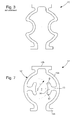
figures 4 et 5 , on décrit ci-après un palier amortisseur de chocs 100 selon l'invention destinée à éviter la rupture ou le décentrage du tigeron 202 d'un axe de balancier 200 d'une pièce d'horlogerie. Les éléments de construction identiques ou analogues à ceux de l'art antérieur illustré en préambule par lesfigures 1 et 2 seront désignés par les mêmes références. - Le palier comporte un bloc support 1 de forme circulaire délimitant un logement 6 dont le centre est percé d'un trou 2 pour permettre le passage d'un axe de balancier 200 terminé par un tigeron 202.
- Le bloc support 1 peut être, soit une pièce indépendante chassée ou fixée par tout autre moyen dans le bâti du mouvement horloger, soit faire partie d'une autre pièce du mouvement, tel qu'un pont ou une platine.
- Comme on peut le voir, le chaton 20 qui supporte la pierre percée 4 traversée par le tigeron 3a et la pierre contre-pivot 5 est amorti par un ressort 12.
- En effet, le bloc support 1 comprend un rebord périphérique 9 comportant deux ouvertures 10. Ces ouvertures 10 sont diamétralement opposées et permettant la mise en place du ressort 12. En effet, le rebord périphérique 9 comprend des portions saillantes 11 s'étendant au niveau des ouvertures. Plus précisément, les deux ouvertures 10 permettant d'avoir un rebord périphérique 9 en deux parties identiques. Chaque partie comprend, à chaque extrémité, une portion saillante 11 s'étendant vers le centre de l'ouverture. Ces portions saillantes 11 permettent au ressort 12 d'y prendre appui. Le ressort 12 est un ressort de forme annulaire.
- Dans un premier mode de réalisation visible à la
figure 6 , le ressort 12 est un ressort lyre. Un tel ressort 12 est constitué de deux bras 12a en forme d'arc de cercle reliés entre eux, via une traverse 12b, au niveau d'une de leurs extrémités, le tout formant une forme d'anneau périphérique 12'. Ce ressort 12 présente ainsi deux extrémités libres comprenant chacune une zone d'appui 12c. Une telle zone d'appui 12c peut se présenter sous la forme d'une courbure de chaque bras au niveau de son extrémité libre afin d'élargir la zone. - Cette configuration du ressort permet à celui-ci d'être installé dans le logement 6 du bloc support. En effet, une fois le chaton 20 mis en place, le ressort 12 est installé. Le ressort 12 est installé de sorte à plaquer le chaton dans le logement tout en ayant la traverse 12b et les zones d'appui 12c plaquées contre les portions saillantes 11 du rebord périphérique.
- Pour amortir le chaton lors d'un choc, le ressort 12 comprend au moins une extension 13. Cette extension 13 s'étend depuis l'un des bras 12a du ressort vers son centre. Cette extension faite de matière avec le ressort 12 est utilisé pour exercer une précontrainte sur la pierre contre-pivot et pour ramener le chaton dans le logement lors d'un choc.
- Le ressort 12 est dimensionné afin que seule l'extension soit au contact de la pierre contre-pivot. De même, les bras 12a en forme d'arc de cercle sont formés pour avoir le même centre et former sensiblement un cercle de centre C. Ce centre C devient également le centre du ressort.
- Astucieusement selon l'invention, l'extension comprend, à son extrémité libre, une tête d'appui 14 faite de matière avec l'extension. Cette tête appui 14 présente une forme d'arc de cercle dont l'interface avec l'extension 13 est faite via la face convexe dudit arc de cercle. Chaque tête d'appui à une forme d'arc de cercle ayant une courbure plus importante que celle des bras formant le ressort. Le rayon de l'arc de cercle formant la tête d'appui est donc plus important que si cet arc de cercle avait un rayon dont el centre était le centre C du ressort. On comprend donc que le centre C' de l'arc de cercle de chaque bras est décalé avec le centre C du ressort comme visible à la
figure 7 . L'extension avec sa tête d'appui 14 présente donc une forme similaire à un Té. - Cette conception permet d'obtenir une extension 13 en forme de té dont les bras ont un meilleur contact avec la pierre contre pivot. La tête d'appui 14 de l'extension 13 présente avantageusement une courbure inverse par rapport à celle de l'art antérieur décrit précédemment. Cela permet de forcer le contact avec la pierre « contre pivot » dans les extrémités puisque la tête d'appui à une forme tendant à épouser la forme de la pierre contre-pivot.
- Un avantage de cette configuration est d'avoir plusieurs points de contacts. Effectivement, la forme de la tête d'appui 14 lui permet d'être, au repos, au contact de la pierre contre-pivot 5 en deux endroits E1 et E2. Cette augmentation du nombre de point de contact permet d'avoir une meilleure stabilité de l'appui sur la pierre contre-pivot 5.
- Lors d'un choc, le chaton 20 est déplacé par l'axe et son tigeron. Ce déplacement du chaton 20 est amorti par le ressort 12. Ce ressort 12 sous l'effet de la contrainte exercée par le chaton 20, se déforme. Dans le cas du ressort 12 selon l'invention, la déformation suite à un choc a pour effet de décaler les points de contacts E1, E2. Ces points de contacts E1, E2 ont ainsi tendance à se rapprocher du centre de la tête d'appui 14. Ce décalage des points de contacts E1, E2 est dû à la forme spécifique de la tête d'appui.
- Or, la zone centrale de la tête d'appui 14 est la partie la plus rigide de sorte que la déformation de cette partie 14 est moins aisée. Par conséquent, plus le choc est important et plus le contact entre l'extension 13 du ressort 12 et la pierre contre-pivot 5 se fait sur la zone la plus rigide de ladite extension. Cela permet ainsi d'obtenir un meilleur amortissement lors de grands chocs.
- Cette configuration de ressort 12 permet également d'avoir une meilleure vue sur le lubrifiant. Dans un chaton 20 tel que décrit, le lubrifiant est agencé entre la pierre percée et la pierre contre-pivot. Avec la configuration de l'extension 13 et notamment de la tête d'appui, la vue sur le centre de la pierre contre-pivot est libérée et définie. Cela est possible de par la forme de la ou des têtes d'appui qui tendent à délimiter une zone. Avec une forme d'arc de cercle dont l'interface avec l'extension se fait par la face concave, les extensions du ressort doivent être plus longues et les têtes d'appuis offre un visuel ne délimitant pas de zone et bouchant la vue sur le lubrifiant.
- Dans une variante visible à la
figure 7 , il sera possible d'avoir un ressort 12 muni de deux extensions 13, ces extensions étant disposées idéalement de façon diamétralement opposée. - Dans une autre variante visible à la
figure 8 , il sera possible d'avoir un ressort 12 muni de trois extensions 13, ces extensions étant disposées de façon à être angulairement répartie. Le ressort 12 comprend ainsi 3 bras 12a. Cette répartition se fera idéalement avec un angle de 60 degré. Dans cette variante, chaque extension présente ainsi son centre C'. - Dans un second mode de réalisation visible à la
figure 9 , le ressort 12 est un anneau ressort 120. Un tel anneau ressort 301 comprend des extensions radiales internes 121 disposées entre des parties annulaires 122. Ces extensions radiales internes 121 sont constituées par la bande formant l'anneau 120 qui est recourbée vers l'intérieur de l'anneau le tout formant une forme d'anneau périphérique 12'. Ces extensions radiales internes 121 sont, de préférence, régulièrement réparties sur le tour de l'anneau plat 120 de sorte que ce dernier puisse agir de façon homogène. Ces extensions radiales internes 121 comprennent chacune la tète d'appui 14 selon l'invention. On comprend alors que l'anneau ressort 120 peut être orienté d'une manière quelconque par rapport au bloc-support 1. Ce bloc support 1 comprend également un rebord périphérique muni d'une portion saillante périphérique s'étendant vers l'intérieur du bloc support. La portion saillante périphérique pourra comprendre une encoche permettant la mise en place de l'anneau ressort 120, ladite portion saillante périphérique servant à retenir l'anneau ressort en place. - Préférentiellement, l'anneau ressort pourra comprendre trois extensions radiales internes. Dans ce cas-là, la portion saillante périphérique pourra comprendre trois encoches permettant la mise en place de l'anneau ressort via une insertion en baïonnette, ladite extension servant à retenir l'anneau ressort en place.
- On comprendra que diverses modifications et/ou améliorations et/ou combinaisons évidentes pour l'homme du métier peuvent être apportées aux différents modes de réalisation de l'invention exposée ci-dessus sans sortir du cadre de l'invention définie par les revendications annexées.
Claims (7)
- Palier amortisseur de chocs pour un tigeron (3a) d'un axe (3) d'un mobile d'une pièce d'horlogerie comportant un bloc support (1) destiné à être chassé, fixé ou formé dans le bâti de ladite pièce d'horlogerie, ledit bloc support (1) étant pourvu d'un logement (6) prévu pour recevoir un ressort (12) à déformation axiale et un chaton (20) supportant une pierre percée (4) traversée par le tigeron (3a) et une pierre contre-pivot (5), le ressort (12) étant agencé dans le logement (6) entre le chaton et au moins une portion saillante d'un rebord périphérique du bloc-support, caractérisé en ce que le ressort (12) est formé par un anneau périphérique (12') à partir duquel s'étendent au moins une extension (13, 121) muni d'une tête d'appui (14) en contact avec la pierre contre-pivot, cette tête d'appui ayant une forme d'arc de cercle dont l'interface avec l'extension se fait via sa face convexe.
- Palier amortisseur de chocs selon la revendication 1, caractérisé en ce que ledit ressort comporte deux bras (12a) en forme d'arc de cercle reliés entre eux via une traverse (12b) et présentant deux extrémités libres comprenant chacune une zone d'appui (12c), ladite au moins une extension s'étendant depuis l'un des deux bras (12a).
- Palier amortisseur de chocs selon la revendication 2, caractérisé en ce que ladite tête d'appui (14) présente une courbure supérieure à celle des bras (12a)
- Palier amortisseur de chocs selon la revendication 1, caractérisé en ce que ledit ressort est formée d'une bande courbée afin de réaliser des extensions radiales internes (121) disposées entre des parties annulaires (122), lesdites extensions radiales internes (121) portant les tête d'appui.
- Palier amortisseur de chocs selon l'une des revendications précédentes, caractérisé en ce que le ressort comprend deux extensions diamétralement opposées.
- Palier amortisseur de chocs selon l'une des revendications précédentes, caractérisé en ce que le ressort comprend trois extensions.
- Palier amortisseur de chocs selon la revendication 6, caractérisé en ce que les trois extensions sont régulièrement réparties.
Priority Applications (2)
| Application Number | Priority Date | Filing Date | Title |
|---|---|---|---|
| EP16186261.0A EP3291026B1 (fr) | 2016-08-30 | 2016-08-30 | Palier amortisseur de chocs pour pièce d'horlogerie |
| CN201721029367.1U CN207133591U (zh) | 2016-08-30 | 2017-08-17 | 用于钟表件的减震器轴承 |
Applications Claiming Priority (1)
| Application Number | Priority Date | Filing Date | Title |
|---|---|---|---|
| EP16186261.0A EP3291026B1 (fr) | 2016-08-30 | 2016-08-30 | Palier amortisseur de chocs pour pièce d'horlogerie |
Publications (2)
| Publication Number | Publication Date |
|---|---|
| EP3291026A1 true EP3291026A1 (fr) | 2018-03-07 |
| EP3291026B1 EP3291026B1 (fr) | 2020-01-01 |
Family
ID=56842737
Family Applications (1)
| Application Number | Title | Priority Date | Filing Date |
|---|---|---|---|
| EP16186261.0A Active EP3291026B1 (fr) | 2016-08-30 | 2016-08-30 | Palier amortisseur de chocs pour pièce d'horlogerie |
Country Status (2)
| Country | Link |
|---|---|
| EP (1) | EP3291026B1 (fr) |
| CN (1) | CN207133591U (fr) |
Families Citing this family (1)
| Publication number | Priority date | Publication date | Assignee | Title |
|---|---|---|---|---|
| EP3671368B1 (fr) | 2018-12-20 | 2022-11-23 | The Swatch Group Research and Development Ltd | Palier, notamment amortisseur de choc, et mobile tournant d'un mouvement horloger |
Citations (9)
| Publication number | Priority date | Publication date | Assignee | Title |
|---|---|---|---|---|
| CH208022A (fr) * | 1938-10-13 | 1939-12-31 | Colomb Henri | Palier amortisseur de chocs. |
| FR927029A (fr) * | 1945-05-02 | 1947-10-17 | Dispositif pour la fixation élastique d'un palier, notamment d'un palier pour axe de balancier de montre | |
| CH294057A (fr) * | 1950-10-19 | 1953-10-31 | Parechoc Sa | Dispositif de montage d'un contre-pivot d'axe d'horlogerie sur son support. |
| CH294058A (fr) * | 1949-12-17 | 1953-10-31 | Tech De L Ind Horlogere Centre | Palier amortisseur de chocs pour mobiles de pièces d'horlogerie. |
| CH325895A (fr) * | 1955-06-25 | 1957-11-30 | Seitz & Co | Palier pare-chocs |
| CH335173A (fr) * | 1957-01-28 | 1958-12-31 | Schwartzmann Marcel Auguste An | Palier amortisseur de chocs pour mobile d'horlogerie |
| FR1532798A (fr) | 1967-07-21 | 1968-07-12 | Palier amortisseur de chocs pour mobile d'horlogerie | |
| JPS5226569U (fr) * | 1975-08-14 | 1977-02-24 | ||
| EP1705537A1 (fr) * | 2005-03-23 | 2006-09-27 | Rolex S.A. | Palier amortisseur de chocs pour pièce d'horlogerie |
-
2016
- 2016-08-30 EP EP16186261.0A patent/EP3291026B1/fr active Active
-
2017
- 2017-08-17 CN CN201721029367.1U patent/CN207133591U/zh active Active
Patent Citations (9)
| Publication number | Priority date | Publication date | Assignee | Title |
|---|---|---|---|---|
| CH208022A (fr) * | 1938-10-13 | 1939-12-31 | Colomb Henri | Palier amortisseur de chocs. |
| FR927029A (fr) * | 1945-05-02 | 1947-10-17 | Dispositif pour la fixation élastique d'un palier, notamment d'un palier pour axe de balancier de montre | |
| CH294058A (fr) * | 1949-12-17 | 1953-10-31 | Tech De L Ind Horlogere Centre | Palier amortisseur de chocs pour mobiles de pièces d'horlogerie. |
| CH294057A (fr) * | 1950-10-19 | 1953-10-31 | Parechoc Sa | Dispositif de montage d'un contre-pivot d'axe d'horlogerie sur son support. |
| CH325895A (fr) * | 1955-06-25 | 1957-11-30 | Seitz & Co | Palier pare-chocs |
| CH335173A (fr) * | 1957-01-28 | 1958-12-31 | Schwartzmann Marcel Auguste An | Palier amortisseur de chocs pour mobile d'horlogerie |
| FR1532798A (fr) | 1967-07-21 | 1968-07-12 | Palier amortisseur de chocs pour mobile d'horlogerie | |
| JPS5226569U (fr) * | 1975-08-14 | 1977-02-24 | ||
| EP1705537A1 (fr) * | 2005-03-23 | 2006-09-27 | Rolex S.A. | Palier amortisseur de chocs pour pièce d'horlogerie |
Also Published As
| Publication number | Publication date |
|---|---|
| CN207133591U (zh) | 2018-03-23 |
| EP3291026B1 (fr) | 2020-01-01 |
Similar Documents
| Publication | Publication Date | Title |
|---|---|---|
| EP1696286B1 (fr) | Palier amortisseur de chocs pour pièce d'horlogerie | |
| EP3220211B1 (fr) | Systeme antichoc a blocage angulaire | |
| WO2014187858A1 (fr) | Amortisseur de choc a baionette | |
| EP2469357A1 (fr) | Palier amortisseur de chocs pour un mobile tournant d'un mouvement d'horlogerie | |
| EP2864843B1 (fr) | Système antichoc non démontable pour pièce d'horlogerie | |
| EP1705537A1 (fr) | Palier amortisseur de chocs pour pièce d'horlogerie | |
| CH705112B1 (fr) | Palier amortisseur de chocs pour pièce d'horlogerie. | |
| EP3011396B1 (fr) | Systeme antichoc a montage securise | |
| EP3291026B1 (fr) | Palier amortisseur de chocs pour pièce d'horlogerie | |
| WO2013190012A1 (fr) | Systeme antichoc a montage simplifie pour piece d'horlogerie | |
| CH708811B1 (fr) | Dispositif de remontage automatique pour montre. | |
| CH708089B1 (fr) | Amortisseur de choc monobloc avec lubrification. | |
| CH712862A2 (fr) | Palier amortisseur de chocs pour pièce d'horlogerie. | |
| CH698675B1 (fr) | Palier amortisseur de chocs pour pièce d'horlogerie. | |
| CH708090B1 (fr) | Dispositif amortisseur de choc à baïonnette. | |
| CH712854A1 (fr) | Porte-piton et procédé de réglage de la position d'un piton dans un tel porte-piton. | |
| CH706640A2 (fr) | Palier antichoc pour pièce d'horlogerie. | |
| CH712187B1 (fr) | Dispositif amortisseur de chocs pour un axe d'un mobile d'une pièce d'horlogerie comportant un anneau ressort monté à baïonnette. | |
| EP3428738B1 (fr) | Système d'entraînement et de positionnement et sautoir pour la mise en oeuvre dudit système | |
| CH706639A2 (fr) | Palier antichoc non demontable pour pièce d'horlogerie. | |
| CH707343B1 (fr) | Palier antichoc pour pièce d'horlogerie. | |
| CH711900A2 (fr) | Porte-piton à montage sécurisé. | |
| CH713946A2 (fr) | Palier amortisseur de choc pour un axe d'un mobile d'une pièce d'horlogerie. | |
| CH550966A (it) | Lampadario da soffitto. | |
| CH708223B1 (fr) | Dispositif amortisseur de chocs pour pièces d'horlogerie. |
Legal Events
| Date | Code | Title | Description |
|---|---|---|---|
| PUAI | Public reference made under article 153(3) epc to a published international application that has entered the european phase |
Free format text: ORIGINAL CODE: 0009012 |
|
| STAA | Information on the status of an ep patent application or granted ep patent |
Free format text: STATUS: THE APPLICATION HAS BEEN PUBLISHED |
|
| AK | Designated contracting states |
Kind code of ref document: A1 Designated state(s): AL AT BE BG CH CY CZ DE DK EE ES FI FR GB GR HR HU IE IS IT LI LT LU LV MC MK MT NL NO PL PT RO RS SE SI SK SM TR |
|
| AX | Request for extension of the european patent |
Extension state: BA ME |
|
| STAA | Information on the status of an ep patent application or granted ep patent |
Free format text: STATUS: REQUEST FOR EXAMINATION WAS MADE |
|
| 17P | Request for examination filed |
Effective date: 20180907 |
|
| RBV | Designated contracting states (corrected) |
Designated state(s): AL AT BE BG CH CY CZ DE DK EE ES FI FR GB GR HR HU IE IS IT LI LT LU LV MC MK MT NL NO PL PT RO RS SE SI SK SM TR |
|
| GRAP | Despatch of communication of intention to grant a patent |
Free format text: ORIGINAL CODE: EPIDOSNIGR1 |
|
| STAA | Information on the status of an ep patent application or granted ep patent |
Free format text: STATUS: GRANT OF PATENT IS INTENDED |
|
| RIC1 | Information provided on ipc code assigned before grant |
Ipc: G04B 31/04 20060101AFI20190627BHEP |
|
| INTG | Intention to grant announced |
Effective date: 20190717 |
|
| GRAS | Grant fee paid |
Free format text: ORIGINAL CODE: EPIDOSNIGR3 |
|
| GRAA | (expected) grant |
Free format text: ORIGINAL CODE: 0009210 |
|
| STAA | Information on the status of an ep patent application or granted ep patent |
Free format text: STATUS: THE PATENT HAS BEEN GRANTED |
|
| AK | Designated contracting states |
Kind code of ref document: B1 Designated state(s): AL AT BE BG CH CY CZ DE DK EE ES FI FR GB GR HR HU IE IS IT LI LT LU LV MC MK MT NL NO PL PT RO RS SE SI SK SM TR |
|
| REG | Reference to a national code |
Ref country code: GB Ref legal event code: FG4D Free format text: NOT ENGLISH |
|
| REG | Reference to a national code |
Ref country code: CH Ref legal event code: EP Ref country code: AT Ref legal event code: REF Ref document number: 1220553 Country of ref document: AT Kind code of ref document: T Effective date: 20200115 |
|
| REG | Reference to a national code |
Ref country code: DE Ref legal event code: R096 Ref document number: 602016027188 Country of ref document: DE |
|
| REG | Reference to a national code |
Ref country code: IE Ref legal event code: FG4D Free format text: LANGUAGE OF EP DOCUMENT: FRENCH |
|
| REG | Reference to a national code |
Ref country code: NL Ref legal event code: MP Effective date: 20200101 |
|
| REG | Reference to a national code |
Ref country code: LT Ref legal event code: MG4D |
|
| REG | Reference to a national code |
Ref country code: CH Ref legal event code: NV Representative=s name: ICB INGENIEURS CONSEILS EN BREVETS SA, CH |
|
| PG25 | Lapsed in a contracting state [announced via postgrant information from national office to epo] |
Ref country code: NO Free format text: LAPSE BECAUSE OF FAILURE TO SUBMIT A TRANSLATION OF THE DESCRIPTION OR TO PAY THE FEE WITHIN THE PRESCRIBED TIME-LIMIT Effective date: 20200401 Ref country code: PT Free format text: LAPSE BECAUSE OF FAILURE TO SUBMIT A TRANSLATION OF THE DESCRIPTION OR TO PAY THE FEE WITHIN THE PRESCRIBED TIME-LIMIT Effective date: 20200527 Ref country code: LT Free format text: LAPSE BECAUSE OF FAILURE TO SUBMIT A TRANSLATION OF THE DESCRIPTION OR TO PAY THE FEE WITHIN THE PRESCRIBED TIME-LIMIT Effective date: 20200101 Ref country code: FI Free format text: LAPSE BECAUSE OF FAILURE TO SUBMIT A TRANSLATION OF THE DESCRIPTION OR TO PAY THE FEE WITHIN THE PRESCRIBED TIME-LIMIT Effective date: 20200101 Ref country code: NL Free format text: LAPSE BECAUSE OF FAILURE TO SUBMIT A TRANSLATION OF THE DESCRIPTION OR TO PAY THE FEE WITHIN THE PRESCRIBED TIME-LIMIT Effective date: 20200101 Ref country code: CZ Free format text: LAPSE BECAUSE OF FAILURE TO SUBMIT A TRANSLATION OF THE DESCRIPTION OR TO PAY THE FEE WITHIN THE PRESCRIBED TIME-LIMIT Effective date: 20200101 Ref country code: RS Free format text: LAPSE BECAUSE OF FAILURE TO SUBMIT A TRANSLATION OF THE DESCRIPTION OR TO PAY THE FEE WITHIN THE PRESCRIBED TIME-LIMIT Effective date: 20200101 |
|
| PG25 | Lapsed in a contracting state [announced via postgrant information from national office to epo] |
Ref country code: BG Free format text: LAPSE BECAUSE OF FAILURE TO SUBMIT A TRANSLATION OF THE DESCRIPTION OR TO PAY THE FEE WITHIN THE PRESCRIBED TIME-LIMIT Effective date: 20200401 Ref country code: IS Free format text: LAPSE BECAUSE OF FAILURE TO SUBMIT A TRANSLATION OF THE DESCRIPTION OR TO PAY THE FEE WITHIN THE PRESCRIBED TIME-LIMIT Effective date: 20200501 Ref country code: LV Free format text: LAPSE BECAUSE OF FAILURE TO SUBMIT A TRANSLATION OF THE DESCRIPTION OR TO PAY THE FEE WITHIN THE PRESCRIBED TIME-LIMIT Effective date: 20200101 Ref country code: SE Free format text: LAPSE BECAUSE OF FAILURE TO SUBMIT A TRANSLATION OF THE DESCRIPTION OR TO PAY THE FEE WITHIN THE PRESCRIBED TIME-LIMIT Effective date: 20200101 Ref country code: HR Free format text: LAPSE BECAUSE OF FAILURE TO SUBMIT A TRANSLATION OF THE DESCRIPTION OR TO PAY THE FEE WITHIN THE PRESCRIBED TIME-LIMIT Effective date: 20200101 Ref country code: GR Free format text: LAPSE BECAUSE OF FAILURE TO SUBMIT A TRANSLATION OF THE DESCRIPTION OR TO PAY THE FEE WITHIN THE PRESCRIBED TIME-LIMIT Effective date: 20200402 |
|
| REG | Reference to a national code |
Ref country code: DE Ref legal event code: R097 Ref document number: 602016027188 Country of ref document: DE |
|
| PG25 | Lapsed in a contracting state [announced via postgrant information from national office to epo] |
Ref country code: RO Free format text: LAPSE BECAUSE OF FAILURE TO SUBMIT A TRANSLATION OF THE DESCRIPTION OR TO PAY THE FEE WITHIN THE PRESCRIBED TIME-LIMIT Effective date: 20200101 Ref country code: ES Free format text: LAPSE BECAUSE OF FAILURE TO SUBMIT A TRANSLATION OF THE DESCRIPTION OR TO PAY THE FEE WITHIN THE PRESCRIBED TIME-LIMIT Effective date: 20200101 Ref country code: EE Free format text: LAPSE BECAUSE OF FAILURE TO SUBMIT A TRANSLATION OF THE DESCRIPTION OR TO PAY THE FEE WITHIN THE PRESCRIBED TIME-LIMIT Effective date: 20200101 Ref country code: SM Free format text: LAPSE BECAUSE OF FAILURE TO SUBMIT A TRANSLATION OF THE DESCRIPTION OR TO PAY THE FEE WITHIN THE PRESCRIBED TIME-LIMIT Effective date: 20200101 Ref country code: SK Free format text: LAPSE BECAUSE OF FAILURE TO SUBMIT A TRANSLATION OF THE DESCRIPTION OR TO PAY THE FEE WITHIN THE PRESCRIBED TIME-LIMIT Effective date: 20200101 Ref country code: DK Free format text: LAPSE BECAUSE OF FAILURE TO SUBMIT A TRANSLATION OF THE DESCRIPTION OR TO PAY THE FEE WITHIN THE PRESCRIBED TIME-LIMIT Effective date: 20200101 |
|
| PLBE | No opposition filed within time limit |
Free format text: ORIGINAL CODE: 0009261 |
|
| STAA | Information on the status of an ep patent application or granted ep patent |
Free format text: STATUS: NO OPPOSITION FILED WITHIN TIME LIMIT |
|
| REG | Reference to a national code |
Ref country code: AT Ref legal event code: MK05 Ref document number: 1220553 Country of ref document: AT Kind code of ref document: T Effective date: 20200101 |
|
| 26N | No opposition filed |
Effective date: 20201002 |
|
| PG25 | Lapsed in a contracting state [announced via postgrant information from national office to epo] |
Ref country code: IT Free format text: LAPSE BECAUSE OF FAILURE TO SUBMIT A TRANSLATION OF THE DESCRIPTION OR TO PAY THE FEE WITHIN THE PRESCRIBED TIME-LIMIT Effective date: 20200101 Ref country code: AT Free format text: LAPSE BECAUSE OF FAILURE TO SUBMIT A TRANSLATION OF THE DESCRIPTION OR TO PAY THE FEE WITHIN THE PRESCRIBED TIME-LIMIT Effective date: 20200101 |
|
| PG25 | Lapsed in a contracting state [announced via postgrant information from national office to epo] |
Ref country code: PL Free format text: LAPSE BECAUSE OF FAILURE TO SUBMIT A TRANSLATION OF THE DESCRIPTION OR TO PAY THE FEE WITHIN THE PRESCRIBED TIME-LIMIT Effective date: 20200101 Ref country code: SI Free format text: LAPSE BECAUSE OF FAILURE TO SUBMIT A TRANSLATION OF THE DESCRIPTION OR TO PAY THE FEE WITHIN THE PRESCRIBED TIME-LIMIT Effective date: 20200101 |
|
| PG25 | Lapsed in a contracting state [announced via postgrant information from national office to epo] |
Ref country code: MC Free format text: LAPSE BECAUSE OF FAILURE TO SUBMIT A TRANSLATION OF THE DESCRIPTION OR TO PAY THE FEE WITHIN THE PRESCRIBED TIME-LIMIT Effective date: 20200101 |
|
| PG25 | Lapsed in a contracting state [announced via postgrant information from national office to epo] |
Ref country code: LU Free format text: LAPSE BECAUSE OF NON-PAYMENT OF DUE FEES Effective date: 20200830 |
|
| REG | Reference to a national code |
Ref country code: BE Ref legal event code: MM Effective date: 20200831 |
|
| PG25 | Lapsed in a contracting state [announced via postgrant information from national office to epo] |
Ref country code: IE Free format text: LAPSE BECAUSE OF NON-PAYMENT OF DUE FEES Effective date: 20200830 Ref country code: BE Free format text: LAPSE BECAUSE OF NON-PAYMENT OF DUE FEES Effective date: 20200831 |
|
| PG25 | Lapsed in a contracting state [announced via postgrant information from national office to epo] |
Ref country code: TR Free format text: LAPSE BECAUSE OF FAILURE TO SUBMIT A TRANSLATION OF THE DESCRIPTION OR TO PAY THE FEE WITHIN THE PRESCRIBED TIME-LIMIT Effective date: 20200101 Ref country code: MT Free format text: LAPSE BECAUSE OF FAILURE TO SUBMIT A TRANSLATION OF THE DESCRIPTION OR TO PAY THE FEE WITHIN THE PRESCRIBED TIME-LIMIT Effective date: 20200101 Ref country code: CY Free format text: LAPSE BECAUSE OF FAILURE TO SUBMIT A TRANSLATION OF THE DESCRIPTION OR TO PAY THE FEE WITHIN THE PRESCRIBED TIME-LIMIT Effective date: 20200101 |
|
| PG25 | Lapsed in a contracting state [announced via postgrant information from national office to epo] |
Ref country code: MK Free format text: LAPSE BECAUSE OF FAILURE TO SUBMIT A TRANSLATION OF THE DESCRIPTION OR TO PAY THE FEE WITHIN THE PRESCRIBED TIME-LIMIT Effective date: 20200101 Ref country code: AL Free format text: LAPSE BECAUSE OF FAILURE TO SUBMIT A TRANSLATION OF THE DESCRIPTION OR TO PAY THE FEE WITHIN THE PRESCRIBED TIME-LIMIT Effective date: 20200101 |
|
| P01 | Opt-out of the competence of the unified patent court (upc) registered |
Effective date: 20230701 |
|
| PGFP | Annual fee paid to national office [announced via postgrant information from national office to epo] |
Ref country code: DE Payment date: 20250724 Year of fee payment: 10 |
|
| PGFP | Annual fee paid to national office [announced via postgrant information from national office to epo] |
Ref country code: GB Payment date: 20250724 Year of fee payment: 10 |
|
| PGFP | Annual fee paid to national office [announced via postgrant information from national office to epo] |
Ref country code: FR Payment date: 20250725 Year of fee payment: 10 |
|
| PGFP | Annual fee paid to national office [announced via postgrant information from national office to epo] |
Ref country code: CH Payment date: 20250901 Year of fee payment: 10 |