EP3290936A1 - Battery pack status parallel monitoring device - Google Patents
Battery pack status parallel monitoring device Download PDFInfo
- Publication number
- EP3290936A1 EP3290936A1 EP16868874.5A EP16868874A EP3290936A1 EP 3290936 A1 EP3290936 A1 EP 3290936A1 EP 16868874 A EP16868874 A EP 16868874A EP 3290936 A1 EP3290936 A1 EP 3290936A1
- Authority
- EP
- European Patent Office
- Prior art keywords
- battery pack
- mcu
- bmic
- main mcu
- diagnostic signal
- Prior art date
- Legal status (The legal status is an assumption and is not a legal conclusion. Google has not performed a legal analysis and makes no representation as to the accuracy of the status listed.)
- Granted
Links
- 238000012806 monitoring device Methods 0.000 title claims abstract description 33
- 238000012544 monitoring process Methods 0.000 claims abstract description 92
- 238000004891 communication Methods 0.000 claims abstract description 58
- 238000012546 transfer Methods 0.000 claims abstract description 16
- 238000010586 diagram Methods 0.000 description 10
- 229910001416 lithium ion Inorganic materials 0.000 description 6
- 238000000034 method Methods 0.000 description 6
- HBBGRARXTFLTSG-UHFFFAOYSA-N Lithium ion Chemical compound [Li+] HBBGRARXTFLTSG-UHFFFAOYSA-N 0.000 description 5
- 238000005516 engineering process Methods 0.000 description 5
- PXHVJJICTQNCMI-UHFFFAOYSA-N nickel Substances [Ni] PXHVJJICTQNCMI-UHFFFAOYSA-N 0.000 description 4
- 230000007274 generation of a signal involved in cell-cell signaling Effects 0.000 description 3
- 238000004519 manufacturing process Methods 0.000 description 3
- 239000000470 constituent Substances 0.000 description 2
- 238000003745 diagnosis Methods 0.000 description 2
- WHXSMMKQMYFTQS-UHFFFAOYSA-N Lithium Chemical compound [Li] WHXSMMKQMYFTQS-UHFFFAOYSA-N 0.000 description 1
- OJIJEKBXJYRIBZ-UHFFFAOYSA-N cadmium nickel Chemical compound [Ni].[Cd] OJIJEKBXJYRIBZ-UHFFFAOYSA-N 0.000 description 1
- 238000007796 conventional method Methods 0.000 description 1
- 238000013461 design Methods 0.000 description 1
- 230000000694 effects Effects 0.000 description 1
- 238000004146 energy storage Methods 0.000 description 1
- 229910052744 lithium Inorganic materials 0.000 description 1
- DWDWQJHDVOKTDZ-UHFFFAOYSA-N nickel dihydride Chemical compound [NiH2] DWDWQJHDVOKTDZ-UHFFFAOYSA-N 0.000 description 1
- 229910000652 nickel hydride Inorganic materials 0.000 description 1
- QELJHCBNGDEXLD-UHFFFAOYSA-N nickel zinc Chemical compound [Ni].[Zn] QELJHCBNGDEXLD-UHFFFAOYSA-N 0.000 description 1
- 229920000642 polymer Polymers 0.000 description 1
- 238000012827 research and development Methods 0.000 description 1
Images


Classifications
-
- G—PHYSICS
- G01—MEASURING; TESTING
- G01R—MEASURING ELECTRIC VARIABLES; MEASURING MAGNETIC VARIABLES
- G01R31/00—Arrangements for testing electric properties; Arrangements for locating electric faults; Arrangements for electrical testing characterised by what is being tested not provided for elsewhere
- G01R31/36—Arrangements for testing, measuring or monitoring the electrical condition of accumulators or electric batteries, e.g. capacity or state of charge [SoC]
- G01R31/382—Arrangements for monitoring battery or accumulator variables, e.g. SoC
-
- G—PHYSICS
- G01—MEASURING; TESTING
- G01R—MEASURING ELECTRIC VARIABLES; MEASURING MAGNETIC VARIABLES
- G01R31/00—Arrangements for testing electric properties; Arrangements for locating electric faults; Arrangements for electrical testing characterised by what is being tested not provided for elsewhere
- G01R31/36—Arrangements for testing, measuring or monitoring the electrical condition of accumulators or electric batteries, e.g. capacity or state of charge [SoC]
-
- G—PHYSICS
- G08—SIGNALLING
- G08C—TRANSMISSION SYSTEMS FOR MEASURED VALUES, CONTROL OR SIMILAR SIGNALS
- G08C19/00—Electric signal transmission systems
- G08C19/02—Electric signal transmission systems in which the signal transmitted is magnitude of current or voltage
-
- H—ELECTRICITY
- H01—ELECTRIC ELEMENTS
- H01M—PROCESSES OR MEANS, e.g. BATTERIES, FOR THE DIRECT CONVERSION OF CHEMICAL ENERGY INTO ELECTRICAL ENERGY
- H01M10/00—Secondary cells; Manufacture thereof
- H01M10/42—Methods or arrangements for servicing or maintenance of secondary cells or secondary half-cells
- H01M10/425—Structural combination with electronic components, e.g. electronic circuits integrated to the outside of the casing
-
- H—ELECTRICITY
- H01—ELECTRIC ELEMENTS
- H01M—PROCESSES OR MEANS, e.g. BATTERIES, FOR THE DIRECT CONVERSION OF CHEMICAL ENERGY INTO ELECTRICAL ENERGY
- H01M10/00—Secondary cells; Manufacture thereof
- H01M10/42—Methods or arrangements for servicing or maintenance of secondary cells or secondary half-cells
- H01M10/48—Accumulators combined with arrangements for measuring, testing or indicating the condition of cells, e.g. the level or density of the electrolyte
- H01M10/482—Accumulators combined with arrangements for measuring, testing or indicating the condition of cells, e.g. the level or density of the electrolyte for several batteries or cells simultaneously or sequentially
-
- H—ELECTRICITY
- H01—ELECTRIC ELEMENTS
- H01M—PROCESSES OR MEANS, e.g. BATTERIES, FOR THE DIRECT CONVERSION OF CHEMICAL ENERGY INTO ELECTRICAL ENERGY
- H01M10/00—Secondary cells; Manufacture thereof
- H01M10/42—Methods or arrangements for servicing or maintenance of secondary cells or secondary half-cells
- H01M10/48—Accumulators combined with arrangements for measuring, testing or indicating the condition of cells, e.g. the level or density of the electrolyte
- H01M10/488—Cells or batteries combined with indicating means for external visualization of the condition, e.g. by change of colour or of light density
-
- H—ELECTRICITY
- H04—ELECTRIC COMMUNICATION TECHNIQUE
- H04Q—SELECTING
- H04Q9/00—Arrangements in telecontrol or telemetry systems for selectively calling a substation from a main station, in which substation desired apparatus is selected for applying a control signal thereto or for obtaining measured values therefrom
-
- H—ELECTRICITY
- H01—ELECTRIC ELEMENTS
- H01M—PROCESSES OR MEANS, e.g. BATTERIES, FOR THE DIRECT CONVERSION OF CHEMICAL ENERGY INTO ELECTRICAL ENERGY
- H01M10/00—Secondary cells; Manufacture thereof
- H01M10/42—Methods or arrangements for servicing or maintenance of secondary cells or secondary half-cells
- H01M10/425—Structural combination with electronic components, e.g. electronic circuits integrated to the outside of the casing
- H01M2010/4271—Battery management systems including electronic circuits, e.g. control of current or voltage to keep battery in healthy state, cell balancing
-
- H—ELECTRICITY
- H01—ELECTRIC ELEMENTS
- H01M—PROCESSES OR MEANS, e.g. BATTERIES, FOR THE DIRECT CONVERSION OF CHEMICAL ENERGY INTO ELECTRICAL ENERGY
- H01M10/00—Secondary cells; Manufacture thereof
- H01M10/42—Methods or arrangements for servicing or maintenance of secondary cells or secondary half-cells
- H01M10/425—Structural combination with electronic components, e.g. electronic circuits integrated to the outside of the casing
- H01M2010/4278—Systems for data transfer from batteries, e.g. transfer of battery parameters to a controller, data transferred between battery controller and main controller
-
- Y—GENERAL TAGGING OF NEW TECHNOLOGICAL DEVELOPMENTS; GENERAL TAGGING OF CROSS-SECTIONAL TECHNOLOGIES SPANNING OVER SEVERAL SECTIONS OF THE IPC; TECHNICAL SUBJECTS COVERED BY FORMER USPC CROSS-REFERENCE ART COLLECTIONS [XRACs] AND DIGESTS
- Y02—TECHNOLOGIES OR APPLICATIONS FOR MITIGATION OR ADAPTATION AGAINST CLIMATE CHANGE
- Y02E—REDUCTION OF GREENHOUSE GAS [GHG] EMISSIONS, RELATED TO ENERGY GENERATION, TRANSMISSION OR DISTRIBUTION
- Y02E60/00—Enabling technologies; Technologies with a potential or indirect contribution to GHG emissions mitigation
- Y02E60/10—Energy storage using batteries
Definitions
- the present invention relates to a battery pack state parallel-monitoring device, and more particularly, to a battery pack state parallel-monitoring device which enables achievement of a high-level safety mechanism by using a simple parallel structure including a parallel line connected to a communication line which connects a communication unit and a main MCU to each other and a communication monitoring unit which monitors data transmitted/received between the communication unit and the MCT through the parallel line.
- the secondary batteries which are rechargeable batteries, represent both conventional Ni/Cd batteries and Ni/MH batteries and up-to-date lithium ion batteries.
- the lithium ion batteries among the secondary batteries have the merit of high energy density compared to the conventional Ni/Cd batteries or Ni/MH batteries.
- the lithium ion batteries can be made small in size and light in weight, and are thus used as power sources of mobile devices.
- the scope of use of the lithium ion batteries extend to power sources of electric vehicles, the lithium ion batteries attract attention as next-generation energy storage media.
- a battery pack state monitoring system used in a vehicle requires a high-level safety mechanism so as to monitor, without error, situations that may be dangerous for a vehicle or a driver.
- a BMIC of a battery management system (BMS) of an electric vehicle measures state information such as a voltage, a current, a temperature, and the like of a battery pack by controlling operation of a cell monitoring unit such as an analog front end (AFE), and generates a diagnostic signal from the measured state information to transfer the diagnostic signal to a main MCU and an auxiliary MCU via communication in a vehicle.
- the main MCU and the auxiliary MCU receives the diagnostic signal from the BMIC to monitor the state of the battery pack.
- constituent units for monitoring the state of a battery pack should be designed to satisfy safety requirements.
- conventional battery pack monitoring systems employ a technology for measuring and diagnosing a battery pack by additionally designing a BMIC and a circuit stage or a technology for measuring and diagnosing a battery pack by replacing an existing main MCU for a battery pack monitoring system with a high-performance main MCU having specifications that satisfy high-level safety requirements.
- the technologies for designing the conventional battery pack monitoring systems for satisfying high-level safety requirements have a problem wherein the cost for production increases. Furthermore, according to the technologies for designing the conventional battery pack monitoring systems, the size of a manufactured product increases since the volume of a BMS increases due to the additionally designed BMIC and circuit stage.
- the present invention provides a battery pack state parallel-monitoring device capable of satisfying high-level safety requirements without increasing the cost of production in comparison with conventional battery pack monitoring systems in which a BMIC and a circuit stage are additionally designed or a high-performance BMIC is used.
- the present invention provides a battery pack state parallel-monitoring device capable of satisfying high-level safety requirements without increasing the volume in comparison with conventional battery pack monitoring systems in which a BMIC and a circuit stage are additionally designed.
- a battery pack state parallel-monitoring device having a battery pack configured with a plurality of battery cells, a cell monitoring unit for measuring a state of the plurality of battery cells, a BMIC for generating a diagnostic signal indicating a state of the battery pack through the cell monitoring unit, a main MCU for receiving the diagnostic signal, and an auxiliary MCU for receiving the diagnostic signal and transmitting/receiving data of the main MCU, according to an embodiment of the present invention includes: data lines connecting the BMIC and the main MCU to each other; parallel lines connected in parallel to the data lines; and a communication monitoring unit connected to the parallel lines to monitor data transmitted/received between the BMIC and the main MCU and transfer the monitored data to the auxiliary MCU.
- the monitoring unit may transfer the monitored data to the auxiliary MCU regardless of whether the main MCU has received data normally from the BMIC via the communication unit.
- the battery pack state parallel-monitoring device may further include a control unit configured to control an operation state of the communication monitoring unit.
- the battery pack state parallel-monitoring device may further include a storage unit configured to pre-store operation execution time information indicating a time consumable by the main MCU which has received the diagnostic signal from the BMIC to start execution of an operation corresponding to the diagnostic signal, wherein the control unit may determine whether the main MCU performs the operation within the time indicated by the operation execution time information when the main MCU has received the diagnostic signal from the BMIC, may generate an operation execution command signal for instructing the auxiliary MCU to immediately perform the operation corresponding to the diagnostic signal when the main MCU does not perform the operation within the time indicated by the operation execution time information as a result of the determination, and may transfer the execution command signal to the auxiliary MCU via the communication monitoring unit so that the operation is performed.
- a storage unit configured to pre-store operation execution time information indicating a time consumable by the main MCU which has received the diagnostic signal from the BMIC to start execution of an operation corresponding to the diagnostic signal
- the control unit may determine whether the main MCU performs the operation within the time indicated by the operation execution
- the communication monitoring unit may be configured with a 3-state buffer.
- a battery pack state parallel-monitoring device may satisfy high-level safety requirements without increasing the cost of production in comparison with conventional battery pack monitoring systems in which a BMIC and a circuit stage are additionally designed or a high-performance BMIC is used, since an auxiliary MCU may perform a high-level safety mechanism through a communication monitoring unit which monitors data transmitted/received between an BMIC and a main MCU.
- the battery pack state parallel-monitoring device may satisfy high-level safety requirements without increasing the volume of a BMS in comparison with a conventional technique of additionally designing a BMIC and a circuit stage, by adding a communication monitoring unit and a control unit to a battery pack monitoring system.
- a battery pack according to an embodiment of the present invention may store electric energy and may provide stored electric energy.
- This battery pack may include a plurality of rechargeable battery cells.
- the battery pack may include a batter module configured with a predetermined number of battery cells. That is, since the battery pack may include at least one battery module, the battery pack may include a plurality of battery cells.
- the battery modules may be electrically connected to each other using various methods such as a serial manner and/or a parallel manner so as to satisfy a specification of a load, a battery, or the like.
- the battery cells may be electrically connected to each other using various methods such as a serial manner and/or a parallel manner.
- the type of the battery cell is not particularly limited.
- the battery cell may include a lithium ion cell, a lithium polymer cell, a nickel cadmium cell, a nickel hydride cell, a nickel zinc cell, etc.
- FIG. 1 is a configuration diagram illustrating a conventional battery pack monitoring system.
- a conventional battery pack monitoring system 100 includes a battery pack 110, a battery cell monitoring unit 120, a BMIC 130, a communication unit 140, a main MCU 150, and an auxiliary MCU 160.
- the battery pack 110 includes a plurality of battery cells 111 (111a, 111b, 111n).
- the battery cell monitoring unit 120 measures a voltage value, a current value, a temperature value, and the like from the plurality of battery cells 111 (111a, 111b, 111n) included in the battery pack 110 in response to control of the BMIC 130 to generate a state signal indicating the state of the battery pack.
- the battery cell monitoring unit 120 transfers the generated state signal to the BMIC 130.
- the BMIC 130 receives the state signal generated by the battery cell monitoring unit 120, and generates, from the received state signal, a diagnostic signal indicating a diagnosis according to the state of the battery pack 110.
- the BMIC 130 transfers the generated diagnostic signal to the main MCU 150 and the auxiliary MCU 160 via the communication unit 140 according to a predetermined communication method.
- the communication unit 140 transmits/receives data between the BMIC 130 and the main MCU 150 or between the BMIC 130 and the auxiliary MCU 160 according to a predetermined communication method.
- the main MCU 150 may receive the diagnostic signal from the BMIC 130 via the communication unit 140, and may perform an operation corresponding to the received diagnostic signal.
- the operation represents an operation related to a safety mechanism.
- the auxiliary MCU 160 may receive the diagnostic signal from the BMIC 130 via the communication unit 140, and may transmit/receive data to/from the main MCU 150.
- the auxiliary MCU 160 may determine whether to perform an operation as an auxiliary of an operation related to a safety mechanism according to whether the main MCU 150 performs a corresponding operation according to a received diagnostic signal, and may perform an auxiliary operation related to the safety mechanism when the auxiliary operation is required to be performed as a result of determination.
- FIG. 2 is a configuration diagram illustrating a conventional battery pack monitoring system in which a BMIC and a circuit stage are additionally designed.
- a conventional battery pack monitoring system 200 in which a BMIC and a circuit stage are additionally designed includes a battery pack 210, a battery cell monitoring unit 220, a BMIC 230, a communication unit 240, a main MCU 250, an auxiliary MCU 260, and an additional circuit stage 270.
- the battery pack 210, the battery cell monitoring unit 220, the BMIC 230, the communication unit 240, the main MCU 250, and the auxiliary MCU 260 of the conventional battery pack monitoring system 200 in which a BMIC and a circuit stage are additionally designed are the same as the descriptions of the battery pack 110, the battery cell monitoring unit 120, the BMIC 130, the communication unit 140, the main MCU 150, and the auxiliary MCU 160 of the conventional battery pack monitoring system 100 illustrated in FIG. 1 , and are thus omitted below.
- the additional circuit stage 270 includes an additional battery cell monitoring unit 271, an additional BMIC 272, and an additional communication unit 273.
- the additional battery cell monitoring unit 271 measures a voltage value, a current value, a temperature value, and the like from a plurality of battery cells 211 (211a, 211b, 211n) included in the battery pack 210 in response to control of the additional BMIC 272 to generate a state signal indicating the state of the battery pack.
- the additional battery cell monitoring unit 271 transfers the generated state signal to the additional BMIC 272.
- the additional BMIC 272 receives the state signal generated by the additional battery cell monitoring unit 271, and generates, from the received state signal, a diagnostic signal indicating a diagnosis according to the state of the battery pack 210.
- the additional BMIC 272 transfers the generated diagnostic signal to the auxiliary MCU 260 via the additional communication unit 273 according to a predetermined communication method.
- the additional communication unit 273 transmits/receives data between the additional BMIC 272 and the auxiliary MCU 260 according to a predetermined communication method.
- the auxiliary MCU 260 may receive the diagnostic signal from the BMIC 230 via the communication unit 240.
- auxiliary MCU 260 may receive the diagnostic signal from the additional BMIC 272 via the additional communication unit 273 of the additional circuit stage.
- auxiliary MCU 260 may transmit/receive data to/from the main MCU 250.
- the auxiliary MCU 260 may determine whether to perform an operation as an auxiliary of an operation related to a safety mechanism according to whether the main MCU 250 performs a corresponding operation according to a received diagnostic signal, and may perform an auxiliary operation related to the safety mechanism when the auxiliary operation is required to be performed as a result of determination.
- the conventional battery pack monitoring system 200 described above with reference to FIG. 2 in which a BMIC and a circuit stage are additionally designed, may perform a higher-level safety mechanism than that of the conventional battery pack monitoring system 100 described above with reference to FIG. 1 , but has disadvantages of increasing the cost of producing a BMS and increasing the volume of a produced BMS.
- FIG. 3 is a configuration diagram illustrating a conventional battery pack monitoring system in which a main MCU is replaced with a high-performance MCU.
- a conventional battery pack monitoring system 300 in which a main MCU is placed with a high-performance MCU includes a battery pack 310, a battery cell monitoring unit 320, a BMIC 330, a communication unit 340, a high-performance MCU 350, and an auxiliary MCU 360.
- the battery pack 310, the battery cell monitoring unit 320, the BMIC 330, the communication unit 340, and the auxiliary MCU 260 of the conventional battery pack monitoring system 300 in which a main MCU is replaced with a high-performance MCU are the same as the descriptions of the battery pack 110, the battery cell monitoring unit 120, the BMIC 130, the communication unit 140, and the auxiliary MCU 160 of the conventional battery pack monitoring system 100 illustrated in FIG. 1 , and are thus omitted below.
- the high-performance MCU 350 is an MCU which accords with a specification satisfying a high-level safety requirement.
- the conventional battery pack monitoring system 300 described above with reference to FIG. 3 in which a main MCU is replaced with a high-performance MCU, may perform a higher-level safety mechanism than that of the conventional battery pack monitoring system 100 described above with reference to FIG. 1 , but has the disadvantage of increasing the cost of producing a BMS.
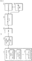
- FIG. 4 is a configuration diagram illustrating a battery pack state monitoring system which includes a battery pack state parallel-monitoring device according to an embodiment of the present invention.
- a battery pack monitoring system 400 including a battery pack state parallel-monitoring device may include a battery pack 410, a battery cell monitoring unit 420, a BMIC 430, a communication unit 440, a main MCU 450, an auxiliary MCU 460, and a battery pack state parallel-monitoring device 470.
- the battery pack 410, the battery cell monitoring unit 420, the BMIC 430, the communication unit 440, the main MCU 450, and the auxiliary MCU 460 of the battery pack monitoring system 400 including the battery pack state parallel-monitoring device are the same as the descriptions of the battery pack 110, the battery cell monitoring unit 120, the BMIC 130, the communication unit 140, the main MCU 150, and the auxiliary MCU 160 of the conventional battery pack monitoring system 100 illustrated in FIG. 1 , and are thus omitted below.
- the battery pack state parallel-monitoring device 470 may include a communication monitoring unit 471, a storage unit 472, and a control unit 473.
- the communication monitoring unit 471 may monitor data transmitted/received between the communication unit 440 and the main MCU 450 in response to control of the control unit 473.
- the communication monitoring unit 471 may monitor the data transmitted/received between the communication unit 440 and the main MCU 450 through parallel lines connected in parallel to data lines which connect the communication unit 440 and the main MCU 450 to each other.
- the communication monitoring unit 471 may monitor whether data is transmitted/received through the data lines which connect the communication unit 440 and the main MCU 450, and, if the data is transmitted/received, may receive the data to transfer the data to the auxiliary MCU 460.
- the communication monitoring unit 471 may be configured with a 3-state buffer, and an operation state of the communication monitoring unit 471 may be determined according to a control signal.
- the communication monitoring unit 471 may transfer monitored data to the auxiliary MCU 460 regardless of whether the main MCU 450 has received data from the BMIC 430 via the communication unit 440.
- the communication monitoring unit 471 transfers the monitored data to the auxiliary MCU 460 regardless of whether the main MCU 450 has received data from the BMIC 430 via the communication unit 440, so that the auxiliary MCU 460 may perform the operation corresponding to the diagnostic signal, thereby achieving a high-level safety mechanism.
- the storage unit 472 may pre-store operation execution time information indicating a time that may be taken for the main MCU 450 which has received the diagnostic signal from the BMIC 430 to start execution of the operation corresponding to the received diagnostic signal.
- the control unit 473 may control operation of the communication monitoring unit 471 and the storage unit 472.
- control unit 473 may further include constituent units as illustrated in FIG. 5 .
- FIG. 5 is a configuration diagram illustrating a control unit of a battery pack state parallel-monitoring device according to an embodiment of the present invention.
- control unit 473 of the battery pack state parallel-monitoring device 470 may further include a main MCU operation execution determining unit 473-1 and an operation execution command signal generation unit 473-2.
- the main MCU operation execution determining unit 473-1 may determine whether the main MCU 450 performs an operation corresponding to a diagnostic signal within the time indicated by the operation execution time information pre-stored in the storage unit 472, when the main MCU 450 has received the diagnostic signal from the BMIC 430.
- the main MCU 450 When the main MCU 450 does not perform the operation corresponding to the diagnostic signal within the time indicated by the operation execution time information pre-stored in the storage unit 472 as a result of the determination, it may be determined that an auxiliary operation of the auxiliary MCU 460 is required.
- the operation execution command signal generation unit 473-2 may generate an operation execution command signal for instructing the auxiliary MCU 460 to immediately perform an operation corresponding to a received diagnostic signal.
- the operation execution command signal generation unit 473-2 may transfer the generated immediate execution command signal to the auxiliary MCU 460 via the communication monitoring unit 471 so that the operation corresponding to the diagnostic signal may be performed.
- the battery pack monitoring system 400 including the battery pack state parallel-monitoring device according to an embodiment of the present invention described above with reference to FIGS. 4 and 5 may perform a high-level safety mechanism with a simple circuit configuration in comparison with the conventional battery pack monitoring systems 100, 200, and 300.
- control unit 473 of the battery pack state parallel-monitoring device 470 determines whether an auxiliary operation is required, a load of the auxiliary MCU 460 may be reduced.
- the battery pack monitoring system 400 including the battery pack state parallel-monitoring device according to an embodiment of the present invention may quickly perform the auxiliary operation for the safety mechanism in comparison with the conventional battery pack monitoring systems 100, 200, and 300.
Abstract
Description
- The present invention relates to a battery pack state parallel-monitoring device, and more particularly, to a battery pack state parallel-monitoring device which enables achievement of a high-level safety mechanism by using a simple parallel structure including a parallel line connected to a communication line which connects a communication unit and a main MCU to each other and a communication monitoring unit which monitors data transmitted/received between the communication unit and the MCT through the parallel line.
- Recently, research and development of secondary batteries has been actively carried out. Here, the secondary batteries, which are rechargeable batteries, represent both conventional Ni/Cd batteries and Ni/MH batteries and up-to-date lithium ion batteries. The lithium ion batteries among the secondary batteries have the merit of high energy density compared to the conventional Ni/Cd batteries or Ni/MH batteries. Furthermore, the lithium ion batteries can be made small in size and light in weight, and are thus used as power sources of mobile devices. Moreover, since the scope of use of the lithium ion batteries extend to power sources of electric vehicles, the lithium ion batteries attract attention as next-generation energy storage media.
- Meanwhile, a battery pack state monitoring system used in a vehicle requires a high-level safety mechanism so as to monitor, without error, situations that may be dangerous for a vehicle or a driver. For example, a BMIC of a battery management system (BMS) of an electric vehicle measures state information such as a voltage, a current, a temperature, and the like of a battery pack by controlling operation of a cell monitoring unit such as an analog front end (AFE), and generates a diagnostic signal from the measured state information to transfer the diagnostic signal to a main MCU and an auxiliary MCU via communication in a vehicle. The main MCU and the auxiliary MCU receives the diagnostic signal from the BMIC to monitor the state of the battery pack. Here, since the operation of monitoring the state of a battery pack per se directly affects the safety of a driver, constituent units for monitoring the state of a battery pack should be designed to satisfy safety requirements.
- In order to satisfy high-level safety requirements, conventional battery pack monitoring systems employ a technology for measuring and diagnosing a battery pack by additionally designing a BMIC and a circuit stage or a technology for measuring and diagnosing a battery pack by replacing an existing main MCU for a battery pack monitoring system with a high-performance main MCU having specifications that satisfy high-level safety requirements.
- However, the technologies for designing the conventional battery pack monitoring systems for satisfying high-level safety requirements have a problem wherein the cost for production increases. Furthermore, according to the technologies for designing the conventional battery pack monitoring systems, the size of a manufactured product increases since the volume of a BMS increases due to the additionally designed BMIC and circuit stage.
- Therefore, it is required to develop a battery pack state parallel-monitoring device, which enables the achievement of a safety mechanism that satisfies high-level safety requirements without additionally designing a BMIC and a circuit stage in a battery monitoring system or replacing an existing main MCU with a high-performance main MCU.
- The present invention provides a battery pack state parallel-monitoring device capable of satisfying high-level safety requirements without increasing the cost of production in comparison with conventional battery pack monitoring systems in which a BMIC and a circuit stage are additionally designed or a high-performance BMIC is used.
- Furthermore, the present invention provides a battery pack state parallel-monitoring device capable of satisfying high-level safety requirements without increasing the volume in comparison with conventional battery pack monitoring systems in which a BMIC and a circuit stage are additionally designed.
- A battery pack state parallel-monitoring device having a battery pack configured with a plurality of battery cells, a cell monitoring unit for measuring a state of the plurality of battery cells, a BMIC for generating a diagnostic signal indicating a state of the battery pack through the cell monitoring unit, a main MCU for receiving the diagnostic signal, and an auxiliary MCU for receiving the diagnostic signal and transmitting/receiving data of the main MCU, according to an embodiment of the present invention includes: data lines connecting the BMIC and the main MCU to each other; parallel lines connected in parallel to the data lines; and a communication monitoring unit connected to the parallel lines to monitor data transmitted/received between the BMIC and the main MCU and transfer the monitored data to the auxiliary MCU.
- The monitoring unit may transfer the monitored data to the auxiliary MCU regardless of whether the main MCU has received data normally from the BMIC via the communication unit.
- The battery pack state parallel-monitoring device may further include a control unit configured to control an operation state of the communication monitoring unit.
- The battery pack state parallel-monitoring device may further include a storage unit configured to pre-store operation execution time information indicating a time consumable by the main MCU which has received the diagnostic signal from the BMIC to start execution of an operation corresponding to the diagnostic signal, wherein the control unit may determine whether the main MCU performs the operation within the time indicated by the operation execution time information when the main MCU has received the diagnostic signal from the BMIC, may generate an operation execution command signal for instructing the auxiliary MCU to immediately perform the operation corresponding to the diagnostic signal when the main MCU does not perform the operation within the time indicated by the operation execution time information as a result of the determination, and may transfer the execution command signal to the auxiliary MCU via the communication monitoring unit so that the operation is performed.
- The communication monitoring unit may be configured with a 3-state buffer.
- A battery pack state parallel-monitoring device according to an embodiment of the present invention may satisfy high-level safety requirements without increasing the cost of production in comparison with conventional battery pack monitoring systems in which a BMIC and a circuit stage are additionally designed or a high-performance BMIC is used, since an auxiliary MCU may perform a high-level safety mechanism through a communication monitoring unit which monitors data transmitted/received between an BMIC and a main MCU.
- Furthermore, the battery pack state parallel-monitoring device according to an embodiment of the present invention may satisfy high-level safety requirements without increasing the volume of a BMS in comparison with a conventional technique of additionally designing a BMIC and a circuit stage, by adding a communication monitoring unit and a control unit to a battery pack monitoring system.
-
-
FIG. 1 is a configuration diagram illustrating a conventional battery pack monitoring system. -
FIG. 2 is a configuration diagram illustrating a conventional battery pack monitoring system in which a BMIC and a circuit stage are additionally designed. -
FIG. 3 is a configuration diagram illustrating a conventional battery pack monitoring system in which a main MCU is replaced with a high-performance MCU. -
FIG. 4 is a configuration diagram illustrating a battery pack state parallel-monitoring system which includes a battery pack state parallel-monitoring device according to an embodiment of the present invention. -
FIG. 5 is a configuration diagram illustrating a control unit of a battery pack state parallel-monitoring device according to an embodiment of the present invention. - Hereinafter, embodiments of the present invention will now be described in detail with reference to the accompanying drawings. The present invention may, however, be embodied in different forms and should not be construed as limited to the embodiments set forth herein. Rather, these embodiments are provided so that this disclosure will be thorough and complete, and will fully convey the scope of the present invention to those skilled in the art.
- A battery pack according to an embodiment of the present invention may store electric energy and may provide stored electric energy. This battery pack may include a plurality of rechargeable battery cells.
- Furthermore, the battery pack may include a batter module configured with a predetermined number of battery cells. That is, since the battery pack may include at least one battery module, the battery pack may include a plurality of battery cells.
- Furthermore, in the case where a plurality of battery modules constitute a battery pack, the battery modules may be electrically connected to each other using various methods such as a serial manner and/or a parallel manner so as to satisfy a specification of a load, a battery, or the like.
- Furthermore, in the case where a plurality of battery cells constitute a battery module, the battery cells may be electrically connected to each other using various methods such as a serial manner and/or a parallel manner. Here, the type of the battery cell is not particularly limited. For example, the battery cell may include a lithium ion cell, a lithium polymer cell, a nickel cadmium cell, a nickel hydride cell, a nickel zinc cell, etc.
- In order to assist with an understanding of a battery pack monitoring system including a battery pack state parallel-monitoring device according to an embodiment of the present invention, a design technology of a conventional battery pack monitoring system will be described with reference to
FIGS. 1 to 3 . -
FIG. 1 is a configuration diagram illustrating a conventional battery pack monitoring system. - Referring to
FIG. 1 , a conventional batterypack monitoring system 100 includes abattery pack 110, a batterycell monitoring unit 120, aBMIC 130, acommunication unit 140, amain MCU 150, and anauxiliary MCU 160. - The
battery pack 110 includes a plurality of battery cells 111 (111a, 111b, 111n). - The battery
cell monitoring unit 120 measures a voltage value, a current value, a temperature value, and the like from the plurality of battery cells 111 (111a, 111b, 111n) included in thebattery pack 110 in response to control of theBMIC 130 to generate a state signal indicating the state of the battery pack. - Thereafter, the battery
cell monitoring unit 120 transfers the generated state signal to theBMIC 130. - The BMIC 130 receives the state signal generated by the battery
cell monitoring unit 120, and generates, from the received state signal, a diagnostic signal indicating a diagnosis according to the state of thebattery pack 110. - Thereafter, the BMIC 130 transfers the generated diagnostic signal to the
main MCU 150 and theauxiliary MCU 160 via thecommunication unit 140 according to a predetermined communication method. - The
communication unit 140 transmits/receives data between theBMIC 130 and themain MCU 150 or between theBMIC 130 and theauxiliary MCU 160 according to a predetermined communication method. - The
main MCU 150 may receive the diagnostic signal from theBMIC 130 via thecommunication unit 140, and may perform an operation corresponding to the received diagnostic signal. Here, the operation represents an operation related to a safety mechanism. - The
auxiliary MCU 160 may receive the diagnostic signal from theBMIC 130 via thecommunication unit 140, and may transmit/receive data to/from themain MCU 150. - Furthermore, the
auxiliary MCU 160 may determine whether to perform an operation as an auxiliary of an operation related to a safety mechanism according to whether themain MCU 150 performs a corresponding operation according to a received diagnostic signal, and may perform an auxiliary operation related to the safety mechanism when the auxiliary operation is required to be performed as a result of determination. -
FIG. 2 is a configuration diagram illustrating a conventional battery pack monitoring system in which a BMIC and a circuit stage are additionally designed. - Referring to
FIG. 2 , a conventional batterypack monitoring system 200 in which a BMIC and a circuit stage are additionally designed includes abattery pack 210, a batterycell monitoring unit 220, aBMIC 230, acommunication unit 240, amain MCU 250, anauxiliary MCU 260, and anadditional circuit stage 270. - Detailed descriptions of the
battery pack 210, the batterycell monitoring unit 220, theBMIC 230, thecommunication unit 240, themain MCU 250, and theauxiliary MCU 260 of the conventional batterypack monitoring system 200 in which a BMIC and a circuit stage are additionally designed are the same as the descriptions of thebattery pack 110, the batterycell monitoring unit 120, theBMIC 130, thecommunication unit 140, themain MCU 150, and theauxiliary MCU 160 of the conventional batterypack monitoring system 100 illustrated inFIG. 1 , and are thus omitted below. - The
additional circuit stage 270 includes an additional batterycell monitoring unit 271, anadditional BMIC 272, and anadditional communication unit 273. - The additional battery
cell monitoring unit 271 measures a voltage value, a current value, a temperature value, and the like from a plurality of battery cells 211 (211a, 211b, 211n) included in thebattery pack 210 in response to control of theadditional BMIC 272 to generate a state signal indicating the state of the battery pack. - Thereafter, the additional battery
cell monitoring unit 271 transfers the generated state signal to theadditional BMIC 272. - The
additional BMIC 272 receives the state signal generated by the additional batterycell monitoring unit 271, and generates, from the received state signal, a diagnostic signal indicating a diagnosis according to the state of thebattery pack 210. - Thereafter, the
additional BMIC 272 transfers the generated diagnostic signal to theauxiliary MCU 260 via theadditional communication unit 273 according to a predetermined communication method. - The
additional communication unit 273 transmits/receives data between theadditional BMIC 272 and theauxiliary MCU 260 according to a predetermined communication method. - The
auxiliary MCU 260 may receive the diagnostic signal from theBMIC 230 via thecommunication unit 240. - Furthermore, the
auxiliary MCU 260 may receive the diagnostic signal from theadditional BMIC 272 via theadditional communication unit 273 of the additional circuit stage. - Furthermore, the
auxiliary MCU 260 may transmit/receive data to/from themain MCU 250. - Furthermore, the
auxiliary MCU 260 may determine whether to perform an operation as an auxiliary of an operation related to a safety mechanism according to whether themain MCU 250 performs a corresponding operation according to a received diagnostic signal, and may perform an auxiliary operation related to the safety mechanism when the auxiliary operation is required to be performed as a result of determination. - The conventional battery
pack monitoring system 200 described above with reference toFIG. 2 , in which a BMIC and a circuit stage are additionally designed, may perform a higher-level safety mechanism than that of the conventional batterypack monitoring system 100 described above with reference toFIG. 1 , but has disadvantages of increasing the cost of producing a BMS and increasing the volume of a produced BMS. -
FIG. 3 is a configuration diagram illustrating a conventional battery pack monitoring system in which a main MCU is replaced with a high-performance MCU. - A conventional battery
pack monitoring system 300 in which a main MCU is placed with a high-performance MCU includes abattery pack 310, a batterycell monitoring unit 320, aBMIC 330, acommunication unit 340, a high-performance MCU 350, and anauxiliary MCU 360. - Detailed descriptions of the
battery pack 310, the batterycell monitoring unit 320, theBMIC 330, thecommunication unit 340, and theauxiliary MCU 260 of the conventional batterypack monitoring system 300 in which a main MCU is replaced with a high-performance MCU are the same as the descriptions of thebattery pack 110, the batterycell monitoring unit 120, theBMIC 130, thecommunication unit 140, and theauxiliary MCU 160 of the conventional batterypack monitoring system 100 illustrated inFIG. 1 , and are thus omitted below. - The high-
performance MCU 350 is an MCU which accords with a specification satisfying a high-level safety requirement. - The conventional battery
pack monitoring system 300 described above with reference toFIG. 3 , in which a main MCU is replaced with a high-performance MCU, may perform a higher-level safety mechanism than that of the conventional batterypack monitoring system 100 described above with reference toFIG. 1 , but has the disadvantage of increasing the cost of producing a BMS. -
FIG. 4 is a configuration diagram illustrating a battery pack state monitoring system which includes a battery pack state parallel-monitoring device according to an embodiment of the present invention. - Referring to
FIG. 4 , a batterypack monitoring system 400 including a battery pack state parallel-monitoring device according to an embodiment of the present invention may include abattery pack 410, a batterycell monitoring unit 420, aBMIC 430, acommunication unit 440, amain MCU 450, anauxiliary MCU 460, and a battery pack state parallel-monitoringdevice 470. - Detailed descriptions of the
battery pack 410, the batterycell monitoring unit 420, theBMIC 430, thecommunication unit 440, themain MCU 450, and theauxiliary MCU 460 of the batterypack monitoring system 400 including the battery pack state parallel-monitoring device according to an embodiment of the present invention are the same as the descriptions of thebattery pack 110, the batterycell monitoring unit 120, theBMIC 130, thecommunication unit 140, themain MCU 150, and theauxiliary MCU 160 of the conventional batterypack monitoring system 100 illustrated inFIG. 1 , and are thus omitted below. - The battery pack state parallel-monitoring
device 470 according to an embodiment of the present invention may include acommunication monitoring unit 471, astorage unit 472, and acontrol unit 473. - The
communication monitoring unit 471 may monitor data transmitted/received between thecommunication unit 440 and themain MCU 450 in response to control of thecontrol unit 473. - In detail, the
communication monitoring unit 471 may monitor the data transmitted/received between thecommunication unit 440 and themain MCU 450 through parallel lines connected in parallel to data lines which connect thecommunication unit 440 and themain MCU 450 to each other. - Furthermore, the
communication monitoring unit 471 may monitor whether data is transmitted/received through the data lines which connect thecommunication unit 440 and themain MCU 450, and, if the data is transmitted/received, may receive the data to transfer the data to theauxiliary MCU 460. - Furthermore, the
communication monitoring unit 471 may be configured with a 3-state buffer, and an operation state of thecommunication monitoring unit 471 may be determined according to a control signal. - Furthermore, the
communication monitoring unit 471 may transfer monitored data to theauxiliary MCU 460 regardless of whether themain MCU 450 has received data from theBMIC 430 via thecommunication unit 440. - In more detail, when an operation corresponding to a diagnostic signal is not performed since the diagnostic signal is not received normally by the
main MCU 450 even though theBMIC 430 has generated and transferred the diagnostic signal to themain MCU 450 via thecommunication unit 440, thecommunication monitoring unit 471 transfers the monitored data to theauxiliary MCU 460 regardless of whether themain MCU 450 has received data from theBMIC 430 via thecommunication unit 440, so that theauxiliary MCU 460 may perform the operation corresponding to the diagnostic signal, thereby achieving a high-level safety mechanism. - The
storage unit 472 may pre-store operation execution time information indicating a time that may be taken for themain MCU 450 which has received the diagnostic signal from theBMIC 430 to start execution of the operation corresponding to the received diagnostic signal. - The
control unit 473 may control operation of thecommunication monitoring unit 471 and thestorage unit 472. - Furthermore, the
control unit 473 may further include constituent units as illustrated inFIG. 5 . -
FIG. 5 is a configuration diagram illustrating a control unit of a battery pack state parallel-monitoring device according to an embodiment of the present invention. - Referring to
FIG. 5 , thecontrol unit 473 of the battery pack state parallel-monitoringdevice 470 according to an embodiment of the present invention may further include a main MCU operation execution determining unit 473-1 and an operation execution command signal generation unit 473-2. - The main MCU operation execution determining unit 473-1 may determine whether the
main MCU 450 performs an operation corresponding to a diagnostic signal within the time indicated by the operation execution time information pre-stored in thestorage unit 472, when themain MCU 450 has received the diagnostic signal from theBMIC 430. - When the
main MCU 450 does not perform the operation corresponding to the diagnostic signal within the time indicated by the operation execution time information pre-stored in thestorage unit 472 as a result of the determination, it may be determined that an auxiliary operation of theauxiliary MCU 460 is required. - When the main MCU operation execution determining unit 473-1 determines that the auxiliary operation of the
auxiliary MCU 460 is required, the operation execution command signal generation unit 473-2 may generate an operation execution command signal for instructing theauxiliary MCU 460 to immediately perform an operation corresponding to a received diagnostic signal. - Thereafter, the operation execution command signal generation unit 473-2 may transfer the generated immediate execution command signal to the
auxiliary MCU 460 via thecommunication monitoring unit 471 so that the operation corresponding to the diagnostic signal may be performed. - The battery
pack monitoring system 400 including the battery pack state parallel-monitoring device according to an embodiment of the present invention described above with reference toFIGS. 4 and5 may perform a high-level safety mechanism with a simple circuit configuration in comparison with the conventional batterypack monitoring systems - Furthermore, since the
control unit 473 of the battery pack state parallel-monitoringdevice 470 according to an embodiment of the present invention determines whether an auxiliary operation is required, a load of theauxiliary MCU 460 may be reduced. - Moreover, when an auxiliary operation for a safety mechanism is required, the battery
pack monitoring system 400 including the battery pack state parallel-monitoring device according to an embodiment of the present invention may quickly perform the auxiliary operation for the safety mechanism in comparison with the conventional batterypack monitoring systems - Although the technical concept of the present invention has been specifically described according to the above-mentioned embodiment, it should be noted that the above-mentioned embodiment is not for limiting the present invention but for describing the present invention. Furthermore, those skilled in the art could understand that various embodiments can be made within the scope of the technical concept of the present invention.
Claims (5)
- A battery pack state parallel-monitoring device having a battery pack configured with a plurality of battery cells, a cell monitoring unit for measuring a state of the plurality of battery cells, a BMIC for generating a diagnostic signal indicating a state of the battery pack through the cell monitoring unit, a main MCU for receiving the diagnostic signal, and an auxiliary MCU for receiving the diagnostic signal and transmitting/receiving data of the main MCU, the battery pack state parallel-monitoring device comprising:data lines connecting the BMIC and the main MCU to each other;parallel lines connected in parallel to the data lines; anda communication monitoring unit connected to the parallel lines to monitor data transmitted/received between the BMIC and the main MCU and transfer the monitored data to the auxiliary MCU.
- The battery pack state parallel-monitoring device of claim 1, wherein the monitoring unit transfers the monitored data to the auxiliary MCU regardless of whether the main MCU has received data normally from the BMIC via the communication unit.
- The battery pack state parallel-monitoring device of claim 1, further comprising a control unit configured to control an operation state of the communication monitoring unit.
- The battery pack state parallel-monitoring device of claim 3, further comprising:a storage unit configured to pre-store operation execution time information indicating a time consumable by the main MCU which has received the diagnostic signal from the BMIC to start execution of an operation corresponding to the diagnostic signal,wherein the control unit determines whether the main MCU performs the operation within the time indicated by the operation execution time information when the main MCU has received the diagnostic signal from the BMIC, generates an operation execution command signal for instructing the auxiliary MCU to immediately perform the operation corresponding to the diagnostic signal when the main MCU does not perform the operation within the time indicated by the operation execution time information as a result of the determination, and transfers the execution command signal to the auxiliary MCU via the communication monitoring unit so that the operation is performed.
- The battery pack state parallel-monitoring device of claim 1, wherein the communication monitoring unit is configured with a 3-state buffer.
Priority Applications (1)
| Application Number | Priority Date | Filing Date | Title |
|---|---|---|---|
| PL16868874T PL3290936T3 (en) | 2015-11-27 | 2016-11-23 | Battery pack status parallel monitoring device |
Applications Claiming Priority (2)
| Application Number | Priority Date | Filing Date | Title |
|---|---|---|---|
| KR1020150167997A KR101945425B1 (en) | 2015-11-27 | 2015-11-27 | Apparatus for monitoring the status of battery pack in parallel |
| PCT/KR2016/013546 WO2017090978A1 (en) | 2015-11-27 | 2016-11-23 | Battery pack status parallel monitoring device |
Publications (3)
| Publication Number | Publication Date |
|---|---|
| EP3290936A1 true EP3290936A1 (en) | 2018-03-07 |
| EP3290936A4 EP3290936A4 (en) | 2018-05-09 |
| EP3290936B1 EP3290936B1 (en) | 2019-08-14 |
Family
ID=58763700
Family Applications (1)
| Application Number | Title | Priority Date | Filing Date |
|---|---|---|---|
| EP16868874.5A Active EP3290936B1 (en) | 2015-11-27 | 2016-11-23 | Battery pack status parallel monitoring device |
Country Status (7)
| Country | Link |
|---|---|
| US (1) | US10627449B2 (en) |
| EP (1) | EP3290936B1 (en) |
| JP (1) | JP6530136B2 (en) |
| KR (1) | KR101945425B1 (en) |
| CN (1) | CN107636480B (en) |
| PL (1) | PL3290936T3 (en) |
| WO (1) | WO2017090978A1 (en) |
Families Citing this family (3)
| Publication number | Priority date | Publication date | Assignee | Title |
|---|---|---|---|---|
| KR102390394B1 (en) | 2018-05-15 | 2022-04-22 | 주식회사 엘지에너지솔루션 | Apparatus and method for controlling main battery and sub battery |
| KR20230056293A (en) * | 2021-10-20 | 2023-04-27 | 주식회사 엘지에너지솔루션 | Battery pack information setting method and battery system using the same |
| KR102621445B1 (en) * | 2023-01-02 | 2024-01-09 | 주식회사 케이에이치티 | Battery Management System for Aircraft and method for controlling thereof |
Family Cites Families (33)
| Publication number | Priority date | Publication date | Assignee | Title |
|---|---|---|---|---|
| JPH04103241A (en) | 1990-08-22 | 1992-04-06 | Fujitsu Ltd | Monitor line duplicate system |
| EP1230683A4 (en) * | 1999-10-28 | 2006-05-17 | Microchip Tech Inc | I2c opto-isolator circuit |
| JP2004150821A (en) * | 2002-10-28 | 2004-05-27 | Sharp Corp | Apparatus for displaying remaining capacity of battery |
| DE102004022624A1 (en) | 2004-05-07 | 2005-12-08 | Robert Bosch Gmbh | Method for monitoring a system |
| JP4171449B2 (en) * | 2004-06-30 | 2008-10-22 | 三洋電機株式会社 | Power supply for vehicle |
| BRPI0610456A2 (en) * | 2005-04-05 | 2010-06-22 | Energycs | system and method for multiplexer and switch-based electrochemical cell monitoring and management |
| KR100990466B1 (en) * | 2005-10-14 | 2010-10-29 | 리서치 인 모션 리미티드 | Battery pack authentication for a mobile device |
| KR100936262B1 (en) * | 2005-10-21 | 2010-01-12 | 주식회사 엘지화학 | Novel Bus Bar for Electric Connection and Middle and Battery Module Comprising the Same |
| KR100991084B1 (en) * | 2005-12-15 | 2010-10-29 | 주식회사 엘지화학 | Multi battery pack system and control method thereof, and battery pack using the same |
| CN101126795A (en) * | 2006-08-14 | 2008-02-20 | 英业达股份有限公司 | Battery performance testing system |
| KR100839382B1 (en) | 2006-10-16 | 2008-06-20 | 삼성에스디아이 주식회사 | Battery management system and driving method thereof |
| WO2010033076A1 (en) | 2008-09-17 | 2010-03-25 | Stl Energy Technology (S) Pte Ltd | Battery pack burn-in test system and method |
| US8598840B2 (en) | 2010-04-15 | 2013-12-03 | Launchpoint Energy And Power Llc | Fault-tolerant battery management system, circuits and methods |
| DE102010041003A1 (en) | 2010-09-20 | 2012-03-22 | Sb Limotive Company Ltd. | Method for monitoring at least two microcontrollers |
| CN103403993B (en) * | 2011-03-05 | 2016-08-24 | 普威能源公司 | Electrical energy storage device |
| KR101856663B1 (en) * | 2011-06-03 | 2018-05-10 | 에스케이이노베이션 주식회사 | Secondary battery sub Unit, Secondary battery management system and Method for exchanging information in multi-pack parallel structure using the same |
| CN102887200B (en) * | 2011-07-18 | 2014-06-25 | 凹凸电子(武汉)有限公司 | Electric bicycle control system and method |
| JP5778536B2 (en) | 2011-09-14 | 2015-09-16 | 株式会社ケーヒン | Electronic control device and vehicle control system |
| KR101678526B1 (en) | 2011-11-17 | 2016-11-23 | 삼성에스디아이 주식회사 | Battery system, method for controlling battery system and energy storage system including the same |
| KR101855092B1 (en) * | 2012-01-18 | 2018-05-08 | 에스케이이노베이션 주식회사 | Relay control signal independent monitoring apparatus and method |
| JP5910129B2 (en) | 2012-02-06 | 2016-04-27 | ソニー株式会社 | Power storage device, power system, and electric vehicle |
| KR101539689B1 (en) | 2012-02-20 | 2015-07-27 | 주식회사 엘지화학 | System and method for identifier allowcation of multi-bms |
| JP5931567B2 (en) * | 2012-04-26 | 2016-06-08 | 株式会社東芝 | Battery module |
| KR101348042B1 (en) * | 2012-05-08 | 2014-01-06 | 넥스콘 테크놀러지 주식회사 | System for automatic shutdown battery monitoring IC of Battery Management System |
| JP5598499B2 (en) | 2012-06-15 | 2014-10-01 | 株式会社デンソー | Battery monitoring device |
| JP5790598B2 (en) * | 2012-07-05 | 2015-10-07 | 株式会社デンソー | Battery control device |
| CN103891097B (en) * | 2012-10-19 | 2016-08-17 | 株式会社Lg化学 | The method of distribution unique identifier and the battery management system of use the method |
| JP6070093B2 (en) * | 2012-11-13 | 2017-02-01 | 三菱自動車工業株式会社 | Power management device |
| JP2014115088A (en) * | 2012-12-06 | 2014-06-26 | Sony Corp | Detection device of remaining capacity of battery, electrically driven vehicle and power supply device |
| JP2015089212A (en) * | 2013-10-30 | 2015-05-07 | 株式会社Gsユアサ | Monitoring system for power storage element |
| DE102013222461B4 (en) * | 2013-11-06 | 2023-07-27 | Robert Bosch Gmbh | Method for starting a battery management system |
| US20150285868A1 (en) * | 2014-04-03 | 2015-10-08 | GM Global Technology Operations LLC | Powerline communication for monitoring of a high number of battery cells |
| US10023112B2 (en) * | 2015-04-23 | 2018-07-17 | Ford Global Technologies, Llc | Battery joint monitoring method and assembly |
-
2015
- 2015-11-27 KR KR1020150167997A patent/KR101945425B1/en active IP Right Grant
-
2016
- 2016-11-23 US US15/578,187 patent/US10627449B2/en active Active
- 2016-11-23 CN CN201680034548.5A patent/CN107636480B/en active Active
- 2016-11-23 JP JP2018514765A patent/JP6530136B2/en active Active
- 2016-11-23 PL PL16868874T patent/PL3290936T3/en unknown
- 2016-11-23 EP EP16868874.5A patent/EP3290936B1/en active Active
- 2016-11-23 WO PCT/KR2016/013546 patent/WO2017090978A1/en active Application Filing
Also Published As
| Publication number | Publication date |
|---|---|
| KR101945425B1 (en) | 2019-02-07 |
| EP3290936A4 (en) | 2018-05-09 |
| US10627449B2 (en) | 2020-04-21 |
| CN107636480A (en) | 2018-01-26 |
| JP6530136B2 (en) | 2019-06-12 |
| EP3290936B1 (en) | 2019-08-14 |
| PL3290936T3 (en) | 2020-03-31 |
| CN107636480B (en) | 2020-05-08 |
| WO2017090978A1 (en) | 2017-06-01 |
| JP2018519532A (en) | 2018-07-19 |
| US20180172769A1 (en) | 2018-06-21 |
| KR20170062328A (en) | 2017-06-07 |
Similar Documents
| Publication | Publication Date | Title |
|---|---|---|
| KR102173777B1 (en) | Master battery management unit and a battery pack including the same | |
| US10193190B2 (en) | Battery control system | |
| US9529053B2 (en) | Battery management system and method for determining the charge state battery cells, battery and motor vehicle comprising a battery management system | |
| EP2523248B1 (en) | Battery control device and method | |
| EP3557687A1 (en) | Battery management unit and battery pack including same | |
| EP2928042B1 (en) | Battery management system capable of transmitting secondary protection signal and diagnostic signal using few insulation elements | |
| KR101440531B1 (en) | Apparatus and method for diagnosis of electric contactor | |
| US20140117939A1 (en) | Secondary battery management system and method for exchanging battery cell information | |
| US11054477B2 (en) | Apparatus, battery system and method for controlling main battery and sub battery | |
| JPWO2015181866A1 (en) | Battery system | |
| KR20150137677A (en) | Method and apparatus for detecting condition of relay | |
| KR20130051228A (en) | Apparatus and method for diagnosis of electric contactor | |
| EP3290936B1 (en) | Battery pack status parallel monitoring device | |
| WO2012157475A1 (en) | Power supply system, method for setting identification information of power supply system, and battery unit | |
| EP3096431B1 (en) | Battery management unit and method for setting identifier by using frequency modulation | |
| KR101817396B1 (en) | Apparatus and method for measuring state of battery health | |
| JP5194669B2 (en) | Power storage system | |
| EP3043441B1 (en) | Battery management unit for preventing performance of erroneous control algorithm from communication error | |
| KR20180051206A (en) | Battery pack | |
| EP3974850A1 (en) | Parallel battery relay diagnosis device and method | |
| JP6721170B1 (en) | Remote monitoring system for emergency charger/discharger | |
| EP3840102B1 (en) | Bms recognition system and method | |
| CN113748046A (en) | Battery management system, battery management method, battery pack, and electric vehicle | |
| JP2016115619A (en) | Battery monitoring system | |
| CN116529980A (en) | Battery control device, operation method thereof and battery control system |
Legal Events
| Date | Code | Title | Description |
|---|---|---|---|
| STAA | Information on the status of an ep patent application or granted ep patent |
Free format text: STATUS: THE INTERNATIONAL PUBLICATION HAS BEEN MADE |
|
| PUAI | Public reference made under article 153(3) epc to a published international application that has entered the european phase |
Free format text: ORIGINAL CODE: 0009012 |
|
| STAA | Information on the status of an ep patent application or granted ep patent |
Free format text: STATUS: REQUEST FOR EXAMINATION WAS MADE |
|
| 17P | Request for examination filed |
Effective date: 20171129 |
|
| AK | Designated contracting states |
Kind code of ref document: A1 Designated state(s): AL AT BE BG CH CY CZ DE DK EE ES FI FR GB GR HR HU IE IS IT LI LT LU LV MC MK MT NL NO PL PT RO RS SE SI SK SM TR |
|
| AX | Request for extension of the european patent |
Extension state: BA ME |
|
| A4 | Supplementary search report drawn up and despatched |
Effective date: 20180410 |
|
| RIC1 | Information provided on ipc code assigned before grant |
Ipc: G08C 19/02 20060101ALI20180403BHEP Ipc: G01R 31/36 20060101AFI20180403BHEP Ipc: H04Q 9/00 20060101ALI20180403BHEP Ipc: H01M 10/42 20060101ALI20180403BHEP |
|
| DAV | Request for validation of the european patent (deleted) | ||
| DAX | Request for extension of the european patent (deleted) | ||
| GRAP | Despatch of communication of intention to grant a patent |
Free format text: ORIGINAL CODE: EPIDOSNIGR1 |
|
| STAA | Information on the status of an ep patent application or granted ep patent |
Free format text: STATUS: GRANT OF PATENT IS INTENDED |
|
| RIC1 | Information provided on ipc code assigned before grant |
Ipc: G08C 19/02 20060101ALI20190412BHEP Ipc: H01M 10/42 20060101ALI20190412BHEP Ipc: G01R 31/36 20190101AFI20190412BHEP Ipc: H01M 10/48 20060101ALI20190412BHEP Ipc: G01R 31/382 20190101ALI20190412BHEP Ipc: H04Q 9/00 20060101ALI20190412BHEP |
|
| INTG | Intention to grant announced |
Effective date: 20190508 |
|
| GRAS | Grant fee paid |
Free format text: ORIGINAL CODE: EPIDOSNIGR3 |
|
| GRAA | (expected) grant |
Free format text: ORIGINAL CODE: 0009210 |
|
| STAA | Information on the status of an ep patent application or granted ep patent |
Free format text: STATUS: THE PATENT HAS BEEN GRANTED |
|
| AK | Designated contracting states |
Kind code of ref document: B1 Designated state(s): AL AT BE BG CH CY CZ DE DK EE ES FI FR GB GR HR HU IE IS IT LI LT LU LV MC MK MT NL NO PL PT RO RS SE SI SK SM TR |
|
| REG | Reference to a national code |
Ref country code: GB Ref legal event code: FG4D |
|
| REG | Reference to a national code |
Ref country code: CH Ref legal event code: EP Ref country code: AT Ref legal event code: REF Ref document number: 1167667 Country of ref document: AT Kind code of ref document: T Effective date: 20190815 |
|
| REG | Reference to a national code |
Ref country code: IE Ref legal event code: FG4D |
|
| REG | Reference to a national code |
Ref country code: DE Ref legal event code: R096 Ref document number: 602016018811 Country of ref document: DE |
|
| REG | Reference to a national code |
Ref country code: NL Ref legal event code: MP Effective date: 20190814 |
|
| REG | Reference to a national code |
Ref country code: LT Ref legal event code: MG4D |
|
| PG25 | Lapsed in a contracting state [announced via postgrant information from national office to epo] |
Ref country code: FI Free format text: LAPSE BECAUSE OF FAILURE TO SUBMIT A TRANSLATION OF THE DESCRIPTION OR TO PAY THE FEE WITHIN THE PRESCRIBED TIME-LIMIT Effective date: 20190814 Ref country code: LT Free format text: LAPSE BECAUSE OF FAILURE TO SUBMIT A TRANSLATION OF THE DESCRIPTION OR TO PAY THE FEE WITHIN THE PRESCRIBED TIME-LIMIT Effective date: 20190814 Ref country code: HR Free format text: LAPSE BECAUSE OF FAILURE TO SUBMIT A TRANSLATION OF THE DESCRIPTION OR TO PAY THE FEE WITHIN THE PRESCRIBED TIME-LIMIT Effective date: 20190814 Ref country code: SE Free format text: LAPSE BECAUSE OF FAILURE TO SUBMIT A TRANSLATION OF THE DESCRIPTION OR TO PAY THE FEE WITHIN THE PRESCRIBED TIME-LIMIT Effective date: 20190814 Ref country code: PT Free format text: LAPSE BECAUSE OF FAILURE TO SUBMIT A TRANSLATION OF THE DESCRIPTION OR TO PAY THE FEE WITHIN THE PRESCRIBED TIME-LIMIT Effective date: 20191216 Ref country code: NO Free format text: LAPSE BECAUSE OF FAILURE TO SUBMIT A TRANSLATION OF THE DESCRIPTION OR TO PAY THE FEE WITHIN THE PRESCRIBED TIME-LIMIT Effective date: 20191114 Ref country code: NL Free format text: LAPSE BECAUSE OF FAILURE TO SUBMIT A TRANSLATION OF THE DESCRIPTION OR TO PAY THE FEE WITHIN THE PRESCRIBED TIME-LIMIT Effective date: 20190814 Ref country code: BG Free format text: LAPSE BECAUSE OF FAILURE TO SUBMIT A TRANSLATION OF THE DESCRIPTION OR TO PAY THE FEE WITHIN THE PRESCRIBED TIME-LIMIT Effective date: 20191114 |
|
| REG | Reference to a national code |
Ref country code: AT Ref legal event code: MK05 Ref document number: 1167667 Country of ref document: AT Kind code of ref document: T Effective date: 20190814 |
|
| PG25 | Lapsed in a contracting state [announced via postgrant information from national office to epo] |
Ref country code: AL Free format text: LAPSE BECAUSE OF FAILURE TO SUBMIT A TRANSLATION OF THE DESCRIPTION OR TO PAY THE FEE WITHIN THE PRESCRIBED TIME-LIMIT Effective date: 20190814 Ref country code: ES Free format text: LAPSE BECAUSE OF FAILURE TO SUBMIT A TRANSLATION OF THE DESCRIPTION OR TO PAY THE FEE WITHIN THE PRESCRIBED TIME-LIMIT Effective date: 20190814 Ref country code: LV Free format text: LAPSE BECAUSE OF FAILURE TO SUBMIT A TRANSLATION OF THE DESCRIPTION OR TO PAY THE FEE WITHIN THE PRESCRIBED TIME-LIMIT Effective date: 20190814 Ref country code: IS Free format text: LAPSE BECAUSE OF FAILURE TO SUBMIT A TRANSLATION OF THE DESCRIPTION OR TO PAY THE FEE WITHIN THE PRESCRIBED TIME-LIMIT Effective date: 20191214 Ref country code: GR Free format text: LAPSE BECAUSE OF FAILURE TO SUBMIT A TRANSLATION OF THE DESCRIPTION OR TO PAY THE FEE WITHIN THE PRESCRIBED TIME-LIMIT Effective date: 20191115 Ref country code: RS Free format text: LAPSE BECAUSE OF FAILURE TO SUBMIT A TRANSLATION OF THE DESCRIPTION OR TO PAY THE FEE WITHIN THE PRESCRIBED TIME-LIMIT Effective date: 20190814 |
|
| PG25 | Lapsed in a contracting state [announced via postgrant information from national office to epo] |
Ref country code: TR Free format text: LAPSE BECAUSE OF FAILURE TO SUBMIT A TRANSLATION OF THE DESCRIPTION OR TO PAY THE FEE WITHIN THE PRESCRIBED TIME-LIMIT Effective date: 20190814 |
|
| PG25 | Lapsed in a contracting state [announced via postgrant information from national office to epo] |
Ref country code: AT Free format text: LAPSE BECAUSE OF FAILURE TO SUBMIT A TRANSLATION OF THE DESCRIPTION OR TO PAY THE FEE WITHIN THE PRESCRIBED TIME-LIMIT Effective date: 20190814 Ref country code: EE Free format text: LAPSE BECAUSE OF FAILURE TO SUBMIT A TRANSLATION OF THE DESCRIPTION OR TO PAY THE FEE WITHIN THE PRESCRIBED TIME-LIMIT Effective date: 20190814 Ref country code: RO Free format text: LAPSE BECAUSE OF FAILURE TO SUBMIT A TRANSLATION OF THE DESCRIPTION OR TO PAY THE FEE WITHIN THE PRESCRIBED TIME-LIMIT Effective date: 20190814 Ref country code: IT Free format text: LAPSE BECAUSE OF FAILURE TO SUBMIT A TRANSLATION OF THE DESCRIPTION OR TO PAY THE FEE WITHIN THE PRESCRIBED TIME-LIMIT Effective date: 20190814 Ref country code: DK Free format text: LAPSE BECAUSE OF FAILURE TO SUBMIT A TRANSLATION OF THE DESCRIPTION OR TO PAY THE FEE WITHIN THE PRESCRIBED TIME-LIMIT Effective date: 20190814 |
|
| PG25 | Lapsed in a contracting state [announced via postgrant information from national office to epo] |
Ref country code: SK Free format text: LAPSE BECAUSE OF FAILURE TO SUBMIT A TRANSLATION OF THE DESCRIPTION OR TO PAY THE FEE WITHIN THE PRESCRIBED TIME-LIMIT Effective date: 20190814 Ref country code: SM Free format text: LAPSE BECAUSE OF FAILURE TO SUBMIT A TRANSLATION OF THE DESCRIPTION OR TO PAY THE FEE WITHIN THE PRESCRIBED TIME-LIMIT Effective date: 20190814 Ref country code: IS Free format text: LAPSE BECAUSE OF FAILURE TO SUBMIT A TRANSLATION OF THE DESCRIPTION OR TO PAY THE FEE WITHIN THE PRESCRIBED TIME-LIMIT Effective date: 20200224 Ref country code: CZ Free format text: LAPSE BECAUSE OF FAILURE TO SUBMIT A TRANSLATION OF THE DESCRIPTION OR TO PAY THE FEE WITHIN THE PRESCRIBED TIME-LIMIT Effective date: 20190814 |
|
| REG | Reference to a national code |
Ref country code: DE Ref legal event code: R097 Ref document number: 602016018811 Country of ref document: DE |
|
| REG | Reference to a national code |
Ref country code: CH Ref legal event code: PL |
|
| PLBE | No opposition filed within time limit |
Free format text: ORIGINAL CODE: 0009261 |
|
| STAA | Information on the status of an ep patent application or granted ep patent |
Free format text: STATUS: NO OPPOSITION FILED WITHIN TIME LIMIT |
|
| PG2D | Information on lapse in contracting state deleted |
Ref country code: IS |
|
| PG25 | Lapsed in a contracting state [announced via postgrant information from national office to epo] |
Ref country code: LU Free format text: LAPSE BECAUSE OF NON-PAYMENT OF DUE FEES Effective date: 20191123 Ref country code: LI Free format text: LAPSE BECAUSE OF NON-PAYMENT OF DUE FEES Effective date: 20191130 Ref country code: MC Free format text: LAPSE BECAUSE OF FAILURE TO SUBMIT A TRANSLATION OF THE DESCRIPTION OR TO PAY THE FEE WITHIN THE PRESCRIBED TIME-LIMIT Effective date: 20190814 Ref country code: CH Free format text: LAPSE BECAUSE OF NON-PAYMENT OF DUE FEES Effective date: 20191130 |
|
| 26N | No opposition filed |
Effective date: 20200603 |
|
| REG | Reference to a national code |
Ref country code: BE Ref legal event code: MM Effective date: 20191130 |
|
| PG25 | Lapsed in a contracting state [announced via postgrant information from national office to epo] |
Ref country code: SI Free format text: LAPSE BECAUSE OF FAILURE TO SUBMIT A TRANSLATION OF THE DESCRIPTION OR TO PAY THE FEE WITHIN THE PRESCRIBED TIME-LIMIT Effective date: 20190814 |
|
| PG25 | Lapsed in a contracting state [announced via postgrant information from national office to epo] |
Ref country code: IE Free format text: LAPSE BECAUSE OF NON-PAYMENT OF DUE FEES Effective date: 20191123 |
|
| PG25 | Lapsed in a contracting state [announced via postgrant information from national office to epo] |
Ref country code: BE Free format text: LAPSE BECAUSE OF NON-PAYMENT OF DUE FEES Effective date: 20191130 |
|
| PG25 | Lapsed in a contracting state [announced via postgrant information from national office to epo] |
Ref country code: CY Free format text: LAPSE BECAUSE OF FAILURE TO SUBMIT A TRANSLATION OF THE DESCRIPTION OR TO PAY THE FEE WITHIN THE PRESCRIBED TIME-LIMIT Effective date: 20190814 |
|
| PG25 | Lapsed in a contracting state [announced via postgrant information from national office to epo] |
Ref country code: HU Free format text: LAPSE BECAUSE OF FAILURE TO SUBMIT A TRANSLATION OF THE DESCRIPTION OR TO PAY THE FEE WITHIN THE PRESCRIBED TIME-LIMIT; INVALID AB INITIO Effective date: 20161123 Ref country code: MT Free format text: LAPSE BECAUSE OF FAILURE TO SUBMIT A TRANSLATION OF THE DESCRIPTION OR TO PAY THE FEE WITHIN THE PRESCRIBED TIME-LIMIT Effective date: 20190814 |
|
| PG25 | Lapsed in a contracting state [announced via postgrant information from national office to epo] |
Ref country code: MK Free format text: LAPSE BECAUSE OF FAILURE TO SUBMIT A TRANSLATION OF THE DESCRIPTION OR TO PAY THE FEE WITHIN THE PRESCRIBED TIME-LIMIT Effective date: 20190814 |
|
| PGFP | Annual fee paid to national office [announced via postgrant information from national office to epo] |
Ref country code: PL Payment date: 20221020 Year of fee payment: 7 |
|
| P01 | Opt-out of the competence of the unified patent court (upc) registered |
Effective date: 20230512 |
|
| REG | Reference to a national code |
Ref country code: DE Ref legal event code: R081 Ref document number: 602016018811 Country of ref document: DE Owner name: LG ENERGY SOLUTION, LTD., KR Free format text: FORMER OWNER: LG CHEM. LTD., SEOUL, KR |
|
| REG | Reference to a national code |
Ref country code: GB Ref legal event code: 732E Free format text: REGISTERED BETWEEN 20230824 AND 20230831 |
|
| PGFP | Annual fee paid to national office [announced via postgrant information from national office to epo] |
Ref country code: GB Payment date: 20231023 Year of fee payment: 8 |
|
| PGFP | Annual fee paid to national office [announced via postgrant information from national office to epo] |
Ref country code: FR Payment date: 20231024 Year of fee payment: 8 Ref country code: DE Payment date: 20231023 Year of fee payment: 8 |
|
| PGFP | Annual fee paid to national office [announced via postgrant information from national office to epo] |
Ref country code: PL Payment date: 20231024 Year of fee payment: 8 |