EP3290884B1 - System und verfahren zur magnetabschirmung für sensoren - Google Patents
System und verfahren zur magnetabschirmung für sensoren Download PDFInfo
- Publication number
- EP3290884B1 EP3290884B1 EP17187466.2A EP17187466A EP3290884B1 EP 3290884 B1 EP3290884 B1 EP 3290884B1 EP 17187466 A EP17187466 A EP 17187466A EP 3290884 B1 EP3290884 B1 EP 3290884B1
- Authority
- EP
- European Patent Office
- Prior art keywords
- coil
- driving
- sensing
- magnetic flux
- magnetic shield
- Prior art date
- Legal status (The legal status is an assumption and is not a legal conclusion. Google has not performed a legal analysis and makes no representation as to the accuracy of the status listed.)
- Active
Links
Images




Classifications
-
- G—PHYSICS
- G01—MEASURING; TESTING
- G01L—MEASURING FORCE, STRESS, TORQUE, WORK, MECHANICAL POWER, MECHANICAL EFFICIENCY, OR FLUID PRESSURE
- G01L1/00—Measuring force or stress, in general
- G01L1/12—Measuring force or stress, in general by measuring variations in the magnetic properties of materials resulting from the application of stress
- G01L1/125—Measuring force or stress, in general by measuring variations in the magnetic properties of materials resulting from the application of stress by using magnetostrictive means
-
- G—PHYSICS
- G01—MEASURING; TESTING
- G01L—MEASURING FORCE, STRESS, TORQUE, WORK, MECHANICAL POWER, MECHANICAL EFFICIENCY, OR FLUID PRESSURE
- G01L1/00—Measuring force or stress, in general
- G01L1/12—Measuring force or stress, in general by measuring variations in the magnetic properties of materials resulting from the application of stress
- G01L1/127—Measuring force or stress, in general by measuring variations in the magnetic properties of materials resulting from the application of stress by using inductive means
-
- G—PHYSICS
- G01—MEASURING; TESTING
- G01L—MEASURING FORCE, STRESS, TORQUE, WORK, MECHANICAL POWER, MECHANICAL EFFICIENCY, OR FLUID PRESSURE
- G01L3/00—Measuring torque, work, mechanical power, or mechanical efficiency, in general
- G01L3/02—Rotary-transmission dynamometers
- G01L3/04—Rotary-transmission dynamometers wherein the torque-transmitting element comprises a torsionally-flexible shaft
- G01L3/10—Rotary-transmission dynamometers wherein the torque-transmitting element comprises a torsionally-flexible shaft involving electric or magnetic means for indicating
- G01L3/101—Rotary-transmission dynamometers wherein the torque-transmitting element comprises a torsionally-flexible shaft involving electric or magnetic means for indicating involving magnetic or electromagnetic means
- G01L3/102—Rotary-transmission dynamometers wherein the torque-transmitting element comprises a torsionally-flexible shaft involving electric or magnetic means for indicating involving magnetic or electromagnetic means involving magnetostrictive means
-
- G—PHYSICS
- G01—MEASURING; TESTING
- G01L—MEASURING FORCE, STRESS, TORQUE, WORK, MECHANICAL POWER, MECHANICAL EFFICIENCY, OR FLUID PRESSURE
- G01L3/00—Measuring torque, work, mechanical power, or mechanical efficiency, in general
- G01L3/02—Rotary-transmission dynamometers
- G01L3/04—Rotary-transmission dynamometers wherein the torque-transmitting element comprises a torsionally-flexible shaft
- G01L3/10—Rotary-transmission dynamometers wherein the torque-transmitting element comprises a torsionally-flexible shaft involving electric or magnetic means for indicating
- G01L3/101—Rotary-transmission dynamometers wherein the torque-transmitting element comprises a torsionally-flexible shaft involving electric or magnetic means for indicating involving magnetic or electromagnetic means
- G01L3/105—Rotary-transmission dynamometers wherein the torque-transmitting element comprises a torsionally-flexible shaft involving electric or magnetic means for indicating involving magnetic or electromagnetic means involving inductive means
-
- H—ELECTRICITY
- H10—SEMICONDUCTOR DEVICES; ELECTRIC SOLID-STATE DEVICES NOT OTHERWISE PROVIDED FOR
- H10N—ELECTRIC SOLID-STATE DEVICES NOT OTHERWISE PROVIDED FOR
- H10N35/00—Magnetostrictive devices
- H10N35/101—Magnetostrictive devices with mechanical input and electrical output, e.g. generators, sensors
Definitions
- the subject matter disclosed herein relates generally to sensors, and more particularly to magnetic shields for magnetostrictive sensors.
- Sensors are used in a variety of industries to sense vibration, torque, speed, force, position, and other parameters.
- the performance of the sensor may decrease due to electrical and/or magnetic interference.
- some sensors may depend on magnetic principles for their operation, and thus a leakage magnetic flux may result in performance degradation.
- US 2015/292962 A1 describes a system which includes a magnetostrictive sensor.
- the magnetostrictive sensor includes a driving coil configured to receive a first driving current and to emit a first magnetic flux portion through a target and a second magnetic flux portion.
- the magnetostrictive sensor also comprises a first sensing coil configured to receive the first magnetic flux portion and to transmit a signal based, at least in part, on the received first magnetic flux portion.
- the first magnetic flux portion being dependent on the force acting on the magnetostrictive target.
- the magnetostrictive sensor further comprises a magnetic shield disposed between the driving coil and the first sensing coil.
- the magnetic shield is configured to reduce the second magnetic flux portion, the leakage flux, received by the first sensing coil.
- the shield may be an active shielding element comprising a flexible printed circuit board rolled up into an annulus that is provided with an additional driving current to emit a counter-active magnetic flux to the leakage magnetic flux, thereby proving an active shielding.
- a system in a first embodiment, includes a magnetostrictive sensor.
- the magnetostrictive sensor includes a driving coil configured to receive a first driving current and to emit a first magnetic flux portion through a magnetostrictive target and a leakage magnetic flux.
- the magnetostrictive sensor also includes a first sensing coil configured to receive the first magnetic flux portion and the leakage magnetic flux, and to transmit a signal based at least in part on the received first magnetic flux portion.
- the received first magnetic flux portion is based at least in part on a force on the magnetostrictive target.
- the magnetostrictive sensor further includes a magnetic shield disposed between the driving coil and the first sensing coil. The magnetic shield is configured to reduce the leakage magnetic fluxreceived by the first sensing coil.
- the magnetic shield comprises a compensation coil without a substrate.
- a sensor that measures a magnetic field through an object may be used to determine a force on the object.
- Sensed magnetic fields that do not extend through the object being measured may affect a quality of the determined force on the object.
- These fields that do not extend through the object being measured may be called leakage magnetic fields.
- embodiments of the disclosed subject matter relate to reducing the leakage magnetic fields that may be sensed by the sensor.
- Embodiments of the disclosed subject matter may use one or more magnetic shields at locations within the sensor to reduce the leakage magnetic fields and to improve the quality of the determined force on the object.
- Ferromagnetic materials have a magnetostrictive property that causes the materials to change shape in the presence of an applied magnetic field. Conversely, when a force is applied to a ferromagnetic material to cause the shape to change, the magnetic properties (e.g., magnetic permeability) of the material also change. Therefore, ferromagnetic materials can convert magnetic energy into potential energy, or potential energy into magnetic energy. Accordingly, ferromagnetic materials may be used for sensors such as force sensors, position sensors, and torque sensors. A magnetostrictive sensor may generate a magnetic flux to pass through a ferromagnetic material.
- a magnetostrictive sensor may include a driving coil to generate magnetic flux and a sensing pole to sense the magnetic flux passing through a ferromagnetic material (e.g., a target material). Because the changes in the measured magnetic flux depend partly on the changes in magnetic permeability of the ferromagnetic material, which in turn are related to the amount of force applied to the ferromagnetic material, measurement of the magnetic flux may be used to sense and/or calculate the value of the applied force. Unfortunately, a leakage magnetic flux from the driving coil to the sensing coil may occur in the magnetostrictive sensor. The leakage magnetic flux does not pass through the ferromagnetic material and, therefore, provides little information on the magnetic permeability of the ferromagnetic material.
- a ferromagnetic material e.g., a target material
- the leakage magnetic flux may be a noise relative to the measured magnetic flux that is from the driving coil to the sensing coil passing through the ferromagnetic material. Such noise may reduce the dynamic range of the magnetostrictive sensor.
- the present disclosure provides a magnetostrictive sensor with a magnetic shield.
- the magnetic shield may be disposed in the space between a driving pole and a sensing pole of the magnetostrictive sensor.
- the magnetic shield may also be disposed about the driving pole.
- the magnetic shield may reduce or eliminate the leakage flux between the driving pole and the sensing pole.
- the resulting magnetostrictive sensor may have an increased dynamic sensing range.
- the magnetic shield may improve the signal to noise ratio of the magnetostrictive sensor.
- the magnetostrictive sensor may use a simpler conditioning circuitry.
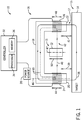
- the magnetostrictive sensing system 10 includes a sensor head 16 positioned proximate to the target material 14, thereby forming a gap 17 between the sensor head 16 and the target material 14.
- the sensor head 16 may be coupled to a frame or fixture to maintain the sensor head 16 in the proper orientation and/or position.
- the sensor head 16 has a core 18 that may be formed from a ferromagnetic material.
- the core 18 has at least two ends, such as a driving pole 20 and a sensing pole 22.
- a driving coil 24 and a sensing coil 26 are disposed about (e.g., wrapped around) the driving pole 20 and the sensing pole 22, respectively.
- a power source 28 e.g., electrical outlet, electrical generator, battery, etc.
- provides an AC current e.g., first driving current
- the first driving current passes through the driving coil 24 to induce a magnetic flux 30 that emanates from the driving coil 24.
- a controller 32 electronically coupled to the power source 28 is configured to control characteristics of the first driving current delivered to the driving coil 24 by the power source 28.
- the controller 32 may control the frequency, amplitude, or the like, of the first driving current.
- the controller 32 may be coupled to the power source 28 by wired or wireless connections.
- Wireless communication devices such as radio transmitters may be integrated with the controller 32 to transmit the signals to a receiver integrated with the power source 28.
- Such machine-readable media can be any available media other than signals that can be accessed by the processor or by any general purpose or special purpose computer or other machine with a processor.
- machine-readable media can include RAM, ROM, EPROM, EEPROM, CD-ROM, or other optical disk storage, magnetic disk storage or other magnetic storage devices, or any other medium which can be used to carry or store desired program code in the form of machine-executable instructions or data structures and which can be accessed by the processor or by any general purpose or special purpose computer or other machine with a processor.
- a network or another communications connection either hardwired, wireless, or a combination of hardwired or wireless
- Machine-executable instructions includes, for example, instructions and data which cause the processor or any general purpose computer, special purpose computer, or special purpose processing machine to perform a certain function or group of functions.
- the processor 34 may execute prestored and/or user-defined algorithms in the memory 36 to calculate the magnitude and/or direction of the force applied to the target material 14 based on the characteristics of the target material 14, the sensor head 16, and the first driving current.
- the signal from the sensing coil 26 may be communicated by wired or wireless connections to the controller 32.
- wireless communication devices such as radio transmitters, may be integrated with the sensor head 16 (e.g., proximate to the sensing coil 26) to transmit the signals to a receiver integrated with the controller 32.
- the signal received from the sensing coil 26 may also be processed with other electronic components, such as an amplifier, a filter, or the like, before or after being processing by the processer 34 of the controller 32.
- a second magnetic flux portion 40 emitted by the driving coil 24 may enter the sensing coil 26 without permeating the target material 14, as illustrated in FIG. 1 .
- the second magnetic flux portion 40 may also be referred to as the leakage magnetic flux 40.
- the leakage magnetic flux 40 provides little information on the magnetic characteristics (e.g., magnetic permeability) of the target material 14 because the leakage magnetic flux 40 does not permeate the target material 14. Accordingly, the leakage magnetic flux 40 may be an undesirable noise signal sensed by the sensing coil 26 relative to the signal from the first magnetic flux portion 38. The noise from the leakage magnetic flux 40 may be significant compared to the measured first magnetic flux portion 38.
- the magnetic shield 12 may help to reduce or eliminate noise associated with the leakage magnetic flux 40 by substantially or entirely blocking the leakage magnetic flux 40. Accordingly, the magnetic shield 12 may improve accuracy of sensor measurements, and thus enable better control of the machine or equipment, such as a turbomachine (e.g., a turbine engine, a compressor, a pump, or a combination thereof), a generator, a combustion engine, or a combination thereof.
- a turbomachine e.g., a turbine engine, a compressor, a pump, or a combination thereof
- a generator e.g., a combustion engine, or a combination thereof.
- the driving coil 24 may also emit the second (i.e., leakage) magnetic flux portion 40 that does not permeate the target material 14.
- the corresponding signal from the leakage magnetic flux 40 sensed by the sensing coil 26 may constitute noise relative to the measured signal from the first magnetic flux portion 38.
- the magnetic shield 12 in accordance with the present disclosure may be disposed between the driving pole (e.g., driving coil 24) and the sensing pole (e.g., sensing coil 26). As illustrated, the magnetic shield 12 is disposed in the space 42 between the driving pole 20 and the sensing pole 22. As discussed in greater detail below, the magnetic shield 12 may be a split tube or annulus formed from a material with a high magnetic permeability that passively shields the sensing coil 26 by reducing or eliminating the leakage flux 40 through the magnetic shield 12 (not forming part of the current invention).
- the magnetic shield 12 may be a rigid or flexible substrate (e.g., printed circuit board, composite, metamaterial, mesh) formed (e.g., rolled up, molded) to a tube or an annulus that passively shields the sensing coil 26 by reducing or eliminating the leakage flux 40 through the magnetic shield 12 (not forming part of the current invention). Additionally, or in the alternative, the magnetic shield 12 may be a rigid or flexible printed circuit board formed (e.g., rolled up, molded) to a tube or annulus that is provided with an additional driving current to emit a counter-active magnetic flux to the leakage magnetic flux 40, thereby providing active magnetic shielding to the sensing coil 26 by reducing or eliminating the leakage flux 40 through the magnetic shield 12.
- a rigid or flexible substrate e.g., printed circuit board, composite, metamaterial, mesh
- the magnetic shield 12 may be a rigid or flexible printed circuit board formed (e.g., rolled up, molded) to a tube or annulus that is provided with an additional driving current to emit a
- the driving coil 24 has a length 44 along an axis 46 substantially perpendicular to the portion in the core 18 connecting the driving pole 20 and the sensing pole 22, and the sensing coil 26 has a length 48 along the axis 46.
- the magnetic shield 12 has a length 50 along an axis 47 parallel to the axis 46. A longer length of the magnetic shield 12 may have less sensed leakage flux than a shorter length of the magnetic shield 12, the length 50 of the magnetic shield 12 is substantially the same or greater than the length 44 of the driving coil 24 and the length 48 of the sensing coil 26. Accordingly, the magnetic shield 12 may be disposed between the driving pole 20 and the sensing pole 22 such that the magnetic shield 12 substantially covers the full length of the driving coil 24 and/or the full length of the sensing coil 26.
- the magnetostrictive sensing system 10 may include more than one magnetic shield 12.
- more than one magnetic shield 12, coupled with each other in any suitable manner e.g., in series, in parallel, concentric, coaxial, telescopic, or any combination thereof, may be disposed in the space 42 between the driving pole 20 and the sensing pole 22.
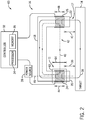
- FIG. 2 illustrates an embodiment of a magnetostrictive sensing system 60 that includes a magnetic shield 11 (e.g., a magnetic shield 62) disposed about (e.g., wrapped around) the driving coil 24 of the driving pole 20. Additionally, or in the alternative, the magnetic shield 62 may be disposed about (e.g., wrapped around) the sensing coil 26 of the sensing pole 22. As discussed in greater detail below, in an example not forming part of the current invention, the magnetic shield 62 may be a split tube or annulus formed from a material with a high magnetic permeability. Additionally, or in the alternative, in another example not forming part of the current invention, the magnetic shield 62 may be a flexible printed circuit board rolled up to a tube or annulus. As illustrated, the leakage magnetic flux 40 sensed by the sensing coil 26 may be reduced or eliminated by the magnetic shield 62. Accordingly, the leakage magnetic flux 40 is illustrated with a dashed line.
- a magnetic shield 11 e.g., a magnetic shield
- FIG. 3 illustrates an example of a magnetic shield 11 (e.g., a magnetic shield 70) not forming part of the current invention, which may be disposed in the space 42 between the driving pole 20 and the sensing pole 22 (e.g., as shown in FIG. 1 ), or disposed about (e.g., wrapped around) the driving coil 24 of the driving pole 20 (e.g., as shown in FIG. 2 ), or a combination thereof.
- An axial axis 72, a radial axis 74, and a circumferential axis 76 are utilized herein to describe the magnetic shield 70.
- the magnetic shield 70 is a split cylindrical tube.
- the magnetic shield 70 has a length 78 along the axial axis 72.
- the magnetic shield 70 includes a shell 80 (e.g., outer annular wall) that has a split 82 (e.g., an axial opening) along the axial axis 72.
- the split 82 of the magnetic shield 70 is for breaking the induced current path around the circumferential axis 76.
- the shell 80 encompasses a space 84 such that the driving pole 20 with the driving coil 24 may be fit into the space 84 without contacting the inside wall 86 of the shell 80.
- the magnetic shield 70 includes a shell 80 without a split 82 (e.g.
- the magnetic shield 70 is substantially a cylindrical tube.
- the magnetic shield 70 may have any suitable shape.
- the cross section of magnetic shield 70 on the plane defined by the axes 74 and 76 may be substantially a square, a rectangle, a triangle, or an oval.
- the magnetic shield 70 may also include a tapered portion at one or both of the two axial ends of the magnetic shield 70.
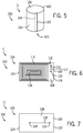
- FIGS. 5, 6, and 7 are diagrams of an example of a magnetic shield 11 not forming part of the current invention, (e.g., a magnetic shield 100) that may be disposed in the space 42 between the driving pole 20 and the sensing pole 22 (e.g., as shown in FIG. 1 ), or disposed about (e.g., wrapped around) the driving coil 24 of the driving pole 20 (e.g., as shown in FIG. 2 ), or a combination thereof.
- the magnetic shield 100 is substantially a cylindrical tube.
- the magnetic shield 100 may have any suitable shape.
- the cross section of the magnetic shield 100 may be substantially a square, a rectangle, a triangle, or an oval.
- the magnetic shield 100 is a substantially rectangular flexible printed circuit board 102 rolled up to a substantially cylindrical tube.
- the magnetic shield 100 has an external side 104 and an internal side 106, which are illustrated in FIGS. 6 and 7 , respectively. These two sides of the magnetic shield 100 may also be referred to herein as the front side 104 and the back side 106 of the printed circuit board 102.
- the magnetic shield 100 may be formed with a conductive layer (e.g., mu-metal, as copper, silver, gold, aluminum, calcium, tungsten, zinc, nickel, lithium, iron, tin, platinum, carbon steel, or any combination thereof) disposed on a rigid insulator (e.g., glass, plastic). That is, the rigid insulator may be formed, printed, or molded into the desirable shape (e.g., annular shape, split ring), then the conductive layer may be applied (e.g., printed, etched) on or within the rigid insulator.
- a conductive layer e.g., mu-metal, as copper, silver, gold, aluminum, calcium, tungsten, zinc, nickel, lithium, iron, tin, platinum, carbon steel, or any combination thereof
- a rigid insulator e.g., glass, plastic. That is, the rigid insulator may be formed, printed, or molded into the desirable shape (e.g., annular shape, split ring), then the conductive
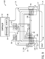
- FIG. 8 illustrates an embodiment of a magnetic shield 11 (e.g., an active magnetic shield 130) in accordance with the present disclosure.
- the magnetic shield 130 may be disposed in the space 42 between the driving pole 20 and the sensing pole 22 of a magnetostrictive sensing system 132 (e.g., as shown in FIG. 1 ).
- the magnetic shield 130 may be generally the same as the magnetic shield 100 in a generally flat fashion as illustrated in FIGS. 6 and 7 (e.g., without being rolled up to a substantially cylindrical tube).
- the magnetic shield 130 is formed with a conductive material (e.g., wire coil, planar coil) that is not formed on a substrate.
- a conductive material e.g., wire coil, planar coil
- the magnetic shield 130 may exclude the resistor 114.
- the magnetic shield 130 is provided with an AC current to emit additional magnetic flux, as described in greater detail below. Accordingly, the magnetic shield 130 may be referred to as an active magnetic shield.
- the magnetic shield 100 is not provided with any current, thereby no additional magnetic flux is emitted by the magnetic shield 100. Accordingly, the magnetic shield 100 described above with FIGS. 5-7 may be referred to as a passive magnetic shield.
- the two ends 112, 116 of the printed pattern 110 in the magnetic shield 130 are not connected with one another via the hole 119 but are electrically coupled to a power source 134.
- the two ends 112, 116 of the conductive material e.g., wire
- the power source 134 may be the same or separate from the power source 28.
- the power source 134 provides an AC current (e.g., a second driving current) to the printed pattern 110 of the active magnetic shield 130.
- the second driving current through the printed pattern 110 induces a third magnetic flux portion 136 and a fourth magnetic flux portion 138.
- the fourth magnetic flux portion 138 has an opposite direction of the leakage magnetic flux 40 at a given time during operation.
- the magnitude of the fourth magnetic flux portion 138 may be tuned to be substantially the same as the magnitude of the leakage magnetic flux 40.
- the overall leakage magnetic flux e.g., sum of the fourth magnetic flux portion 138 and the leakage magnetic flux 40
- the active magnetic shield 130 is provided with a driving current (e.g., the second drive current) to actively emit a magnetic flux (e.g., the fourth magnetic flux portion 138) to negatively counteract the leakage magnetic flux 40
- a driving current e.g., the second drive current
- a magnetic flux e.g., the fourth magnetic flux portion 138
- the printed pattern 110 of the magnetic shield 130 may also be referred to herein as a compensation coil 110.
- the magnitude of the fourth magnetic flux portion 138 may be tuned to be substantially the same as the magnitude of the leakage magnetic flux 40.
- the magnitude of the fourth magnetic flux portion 138 depends, at least, on magnitude of the second driving current and the number of turns of the printed pattern 110 on the substrate layer 108 or conductive coil without a substrate. Accordingly, by tuning the magnitude of the second driving current and/or the number of turns of the printed pattern 110, the magnitude of the fourth magnetic flux portion 138 may be tuned.
- the number of turns of the printed pattern 110 of the magnetic shield 130 is the same as the number of coils of the driving coil 24.
- the conductive coil magnetic shield 133 may be a conductive material 131 (e.g., wire) that is not formed on a substrate. That is, the conductive coil magnetic shield 133 may be an air coil without a substrate. For example, a copper or aluminum coil wound into a helical shape, spiral shape, or cylindrical planar coil shape may be disposed about the driving pole 20. In some embodiments, the conductive coil magnetic shield 133 may be disposed about the driving pole 20 in addition to one or more magnetic shields 130 discussed above with FIG. 8 .
- the conductive material 131 of the conductive coil magnetic shield 133 may be formed in a variety of shapes about the driving coil 24 including, but not limited to, a circular shape, an elliptical shape, a square shape, a rectangular shape, a triangular shape, a hexagonal shape, an octagonal shape, and so forth.
- the magnetostrictive sensing systems 10, 60, 132 may additionally include an outer magnetic shield enclosing the sensor head 16.
- the outer magnetic shield may reduce external electromagnetic interference received by the driving coil and the sensing coil.
- FIG. 10 illustrates a top view of an embodiment of a magnetostrictive sensing system 140 incorporating such an outer magnetic shield 142. As discussed above, the magnetostrictive sensing system 140 includes the sensor head 16.
- the magnetostrictive sensing system 140 also includes the outer magnetic shield 142.
- the outer magnetic shield 142 may include one or more layers for reducing the magnetic interference from an outside source.
- the outer magnetic shield 142 may include, but is not limited to, one or more layers of material with a high conductivity to reduce high frequency interference.
- Such high electrical conductivity material may include copper, silver, gold, aluminum, calcium, tungsten, zinc, nickel, lithium, iron, tin, platinum, carbon steel, or any combination thereof.
- the outer magnetic shield 142 may include one or more layers of material with a high magnetic permeability to reduce low frequency interference.
- material has a relative permeability between approximately 100 to 100,000, 200 to 90,000, 300 to 70,000, 500 to 50,000, 1,000 to 30,000, 2,000 to 20,000, or 5,000 to 10,000.
- high magnetic permeability material may include, but is not limited to, iron, Mu-metal, cobalt-iron, permalloy, nanoperm, electrical steel, ferrite, carbon steel, nickel, or any combination thereof.
- the sensor head 16 includes a driving pole 20 and at least one sensing pole 22 with the corresponding driving coil 24 and at least one sensing coil 26 disposed thereabout, respectively. Some embodiments of the sensor head 16 may include one or more driving poles and one or more sensing poles.
- FIG. 11 is a perspective view of an embodiment of a sensor head 150 with one driving pole 20, 152 and four sensing poles 22, 154, 156, 158, 160.
- FIG. 12 is a top view of the embodiment of the sensor head 150 of FIG. 11 .
- the sensor head 150 includes a core 162.
- the core 162 may be fabricated from any ferromagnetic material (e.g., iron, steel, nickel, cobalt).
- the core 162 has a cross axis yoke 164 with a yoke portion 166.
- Four members 168, 170, 172, 174 of the cross axis yoke 164 extend radially outward in a plane from the yoke portion 166.
- the four members 168, 170, 172, 174 are substantially orthogonal to each other around the yoke portion 166.
- Each of the four members 168, 170, 172, 174 may extend from the yoke portion 166 in any configuration and for any length that enables each member to operate as described herein.
- the yoke 164 may have any number of members that enables the yoke 164 to operate as described herein.
- the sensor head 150 may have 1, 2, 3, 4, 5, 6, 7, 8, 9, 10 or more members that extend radially from the yoke portion 166.
- the one or more members may be angularly spaced apart by approximately 10, 20, 30, 40, 45, 60, 75, 90, 120, or 130 degrees, or any combination thereof.
- the driving pole 152 extends outward from the yoke portion 166 perpendicular to a planar surface defined by the yoke 164.
- the four sensing poles 154, 156, 158, 160 extend outward from the yoke 164 substantially perpendicular to the planar surface defined by the yoke 164 and substantially parallel to driving pole 152.
- the sensing pole 154 extends from the distal end of member 168
- the sensing pole 156 extends from the distal end of member 170
- the sensing pole 158 extends from the distal end of member 172
- the sensing pole 160 extends from the distal end of member 174.
- the core 162 may have any number of poles (including driving poles and sensing poles) extending from the yoke 164 that enables the core 162 to operate as described herein.
- the core may have one driving pole and 1, 2, 3, 4, 5, 6, 7, 8, 9, 10 or more sensing poles extending from the yoke 164.
- a driving coil 176 is disposed about (e.g., wrapped around) the driving pole 152.
- Four detection coils 178, 180, 182, 184 are disposed about (e.g., wrapped around) each of the respective sensing poles 154, 156, 158, 160.
- an AC current is passed through the driving coil 176 to induce the first magnetic flux portion 38.
- the first magnetic flux portion 38 flows from the driving pole 152, through the target material 14, to the four sensing poles 154, 156, 158, 160, where the respective sensing coils 178, 180, 182, 184 detect the first magnetic flux portion 38.
- a change in the first magnetic flux portion 38 due to a force applied to the target material 14 may be measured by the sensing coils 178, 180, 182, 184.
- the driving coil 176 may also emit leakage magnetic fluxes 40 that do not permeate the target material 14.
- the signal from the leakage magnetic fluxes 40 detected by the sensing coils 178, 180, 182, 184 may constitute noise relative to the measured signal from the first magnetic flux portion 38.
- one or more magnetic shields 11 may be disposed in the space between the driving pole 20, 152 and each of the respective sensing poles 22, 154, 156, 158, 160, or one magnetic shield (e.g., the magnetic shield 62, 70, 92, 100, 144) may be disposed about (e.g., wrapped around) the driving coil 24, 176 of the driving pole 20, 152, or any combination thereof.
- more than one magnetic shield e.g., the magnetic shield 70, 92, 100, 130, 133
- any suitable manner e.g., in series, in parallel, concentric, coaxial, telescopic, or any combination thereof
- the subject matter disclosed herein include, but are not limited to, disposing one or more magnetic shields in the magnetostrictive sensing system to reduce or eliminate the leakage flux between the driving pole and the sensing pole.
- the resulting magnetostrictive sensing system may have an increased dynamic sensing range.
- the magnetic shields may improve the signal to noise ratio of the magnetostrictive sensing system.
Landscapes
- Physics & Mathematics (AREA)
- General Physics & Mathematics (AREA)
- Electromagnetism (AREA)
- Measuring Magnetic Variables (AREA)
Claims (8)
- System, umfassend:einen magnetostriktiven Sensor, umfassend:eine Treiberspule (24), die eingerichtet ist, um einen ersten Treiberstrom aufzunehmen und um einen ersten Magnetflussanteil (38) durch ein magnetostriktives Ziel (14) und einen magnetischen Streufluss (40) abzugeben;eine erste Erfassungsspule (26), die eingerichtet ist, um den ersten Magnetflussanteil (38) und den magnetischen Streufluss (40) aufzunehmen und ein Signal zu übertragen, das mindestens teilweise auf dem aufgenommenen ersten Magnetflussanteil (38) beruht, wobei der aufgenommene erste Magnetflussanteil (38) mindestens teilweise auf einer Kraft am magnetostriktiven Ziel (14) beruht;eine Magnetabschirmung (11, 130), die zwischen der Treiberspule (24) und der ersten Erfassungsspule (26) angeordnet ist, wobei die Magnetabschirmung (11, 130) eingerichtet ist, um den magnetischen Streufluss (40) zu verringern, der durch die erste Erfassungsspule (26) aufgenommen wird; undeine Steuereinheit (32), die eingerichtet ist, um einen zweiten Treiberstrom zu steuern;wobei die Magnetabschirmung (11, 130) eine Kompensationsspule (110) ohne ein Substrat (108) umfasst;wobei die Kompensationsspule (110) eingerichtet ist, um den zweiten Treiberstrom aufzunehmen und einen dritten Magnetflussanteil (136), mit einer Größe im Wesentlichen gleich dem magnetischen Streufluss (40) und mit einer Richtung im Wesentlichen entgegengesetzt zum magnetischen Streufluss (40), abzugeben; undwobei die Steuereinheit (32) eingerichtet ist, um den zweiten Treiberstrom, mindestens teilweise auf der Grundlage eines Abstands (42) zwischen der Treiberspule (24) und der ersten Erfassungsspule (26) oder eines Abstands zwischen dem magnetostriktiven Sensor und dem magnetostriktiven Ziel (14) oder einer beliebigen Kombination davon, zu steuern.
- System nach Anspruch 1, umfassend:einen Treiberpol (20), wobei die Treiberspule (24) um den Treiberpol (20) herum angeordnet ist; undeinen ersten Erfassungspol (22), wobei die erste Erfassungsspule (26) um den ersten Erfassungspol (22) herum angeordnet ist.
- System nach Anspruch 2, wobei die Magnetabschirmung (11, 130) um den Treiberpol (20) und die Treiberspule (24) herum angeordnet ist.
- System nach Anspruch 2, umfassend einen zweiten Erfassungspol (154) und eine zweite Erfassungsspule (178), die um den zweiten Erfassungspol (154) herum angeordnet ist, wobei der Treiberpol (20) zwischen der ersten Erfassungsspule (26) und der zweiten Erfassungsspule (178) angeordnet ist.
- System nach einem der vorstehenden Ansprüche, wobei die Steuereinheit (32) eingerichtet ist, um die Kraft zu bestimmen, die auf das magnetostriktive Ziel (14) eines Turbinentriebwerks, eines Verdichters, einer Pumpe, eines Generators oder eines Verbrennungsmotors oder einer beliebigen Kombination davon, ausgeübt wird.
- Verfahren zur Verwendung des Systems nach einem der vorstehenden Ansprüche, wobei das Verfahren folgendes umfasst:Zuführen eines ersten Stroms zu einer Treiberspule (24) eines magnetostriktiven Sensors;Abgeben eines ersten Magnetflussanteils (38) aus der Treiberspule (24) durch das magnetostriktive Ziel (14);Abgeben eines zweiten Magnetflussanteils (40) aus der Treiberspule (24);Erfassen des ersten Magnetflussanteils (38) mit der Erfassungsspule (26) des magnetostriktiven Sensors;Verringern des magnetischen Streuflusses (40), der durch die Erfassungsspule (26) aufgenommen wird, mindestens teilweise auf der Grundlage der Magnetabschirmung (11, 130) des magnetostriktiven Sensors, der zwischen der Treiberspule (24) und der Erfassungsspule (26) angeordnet ist;Zuführen eines zweiten Stroms zur Kompensationsspule (110) der Magnetabschirmung (11, 130), wobei die Kompensationsspule kein Substrat (108) aufweist; unddurch die Kompensationsspule (110), Aufnehmen eines zweiten Stroms;aus der Kompensationsspule (110), Abgeben eines dritten Magnetflussanteils (136) mit einer Größe im Wesentlichen gleich dem magnetischen Streufluss (40) und in einer Richtung im Wesentlichen entgegengesetzt zum magnetischen Streufluss (40);durch die Steuereinheit (32), Steuern des zweiten Treiberstroms mindestens teilweise auf der Grundlage eines Abstands (42) zwischen der Treiberspule (24) und der ersten Erfassungsspule (26) oder eines Abstands zwischen dem magnetostriktiven Sensor und dem magnetostriktiven Ziel (14) oder einer beliebigen Kombination davon.
- Verfahren nach Anspruch 6, umfassend das Verringern von Rauschen, das durch die Sensorspule (26) aufgenommen wird, mindestens teilweise auf der Grundlage eines Gehäuses (142), wobei das Gehäuse eine erste Schicht umfasst, die eingerichtet ist, um die Erfassungsspule (26) gegenüber Hochfrequenzrauschen magnetisch abzuschirmen, und eine zweite Schicht, die eingerichtet ist, um die Erfassungsspule (26) gegenüber Niederfrequenzrauschen magnetisch abzuschirmen.
- Verfahren nach Anspruch 6 oder 7, umfassend:Erzeugen eines Signals, das mindestens teilweise auf dem ersten Magnetflussanteil (38) beruht, der mit der Erfassungsspule (26) erfasst wurde; undBestimmen einer Kraft am magnetostriktiven Ziel (14), mindestens teilweise auf der Grundlage des Signals.
Applications Claiming Priority (1)
| Application Number | Priority Date | Filing Date | Title |
|---|---|---|---|
| US15/250,557 US10094720B2 (en) | 2014-04-10 | 2016-08-29 | System and method of magnetic shielding for sensors |
Publications (2)
| Publication Number | Publication Date |
|---|---|
| EP3290884A1 EP3290884A1 (de) | 2018-03-07 |
| EP3290884B1 true EP3290884B1 (de) | 2020-07-29 |
Family
ID=59858486
Family Applications (1)
| Application Number | Title | Priority Date | Filing Date |
|---|---|---|---|
| EP17187466.2A Active EP3290884B1 (de) | 2016-08-29 | 2017-08-23 | System und verfahren zur magnetabschirmung für sensoren |
Country Status (2)
| Country | Link |
|---|---|
| EP (1) | EP3290884B1 (de) |
| DK (1) | DK3290884T3 (de) |
Family Cites Families (1)
| Publication number | Priority date | Publication date | Assignee | Title |
|---|---|---|---|---|
| US9429488B2 (en) * | 2014-04-10 | 2016-08-30 | General Electric Company | System and method of magnetic shielding for sensors |
-
2017
- 2017-08-23 DK DK17187466.2T patent/DK3290884T3/da active
- 2017-08-23 EP EP17187466.2A patent/EP3290884B1/de active Active
Non-Patent Citations (1)
| Title |
|---|
| None * |
Also Published As
| Publication number | Publication date |
|---|---|
| EP3290884A1 (de) | 2018-03-07 |
| DK3290884T3 (da) | 2020-10-19 |
Similar Documents
| Publication | Publication Date | Title |
|---|---|---|
| US10444086B2 (en) | System and method of magnetic shielding for sensors | |
| EP3129761B1 (de) | System und verfahren zur magnetabschirmung für sensoren | |
| US7906960B2 (en) | Inductive position sensor | |
| US10330499B2 (en) | Micro inductive sensor | |
| US8564281B2 (en) | Noncontact measuring of the position of an object with magnetic flux | |
| JP5839257B2 (ja) | コイル部品並びにそれを用いた給電装置及び充電装置 | |
| JP2012225921A (ja) | 磁気コアを備えている電流センサ | |
| US10359324B2 (en) | Non-contact magnetostrictive sensors and methods of operation of such sensors | |
| JP2013518247A (ja) | 誘導位置センサ | |
| JP6822568B2 (ja) | コイル装置 | |
| US9784627B2 (en) | Load sensor, load detector including load sensor, and method for detecting load | |
| JP2005164531A (ja) | 磁歪式トルクセンサ | |
| US8633703B2 (en) | Inductive conductivity sensor | |
| JP2007208201A (ja) | 非接触型電力供給装置 | |
| EP3290884A1 (de) | System und verfahren zur magnetabschirmung für sensoren | |
| JP4420938B2 (ja) | 核磁気共鳴信号用プローブ | |
| JP5914827B2 (ja) | 力センサ及びそれを用いた力検知装置、並びに力検知方法 | |
| CN106018912A (zh) | 一种高精度通用型交直流电流测量装置 | |
| CN103573247B (zh) | 感应测井平行平面线圈及感应测井设备 | |
| WO2013038591A1 (ja) | 受電装置、送電装置および電力伝送装置 | |
| JP2008203166A (ja) | トルクセンサ及びトルク検出方法 | |
| JP5866515B2 (ja) | 力センサ及びそれを用いた力検知装置 | |
| CN102681016B (zh) | 一种低频磁波动分析仪传感器 | |
| JP2024014772A (ja) | ラウドスピーカ | |
| JP5866517B1 (ja) | 力センサおよびそれを用いた力検知装置 |
Legal Events
| Date | Code | Title | Description |
|---|---|---|---|
| PUAI | Public reference made under article 153(3) epc to a published international application that has entered the european phase |
Free format text: ORIGINAL CODE: 0009012 |
|
| STAA | Information on the status of an ep patent application or granted ep patent |
Free format text: STATUS: THE APPLICATION HAS BEEN PUBLISHED |
|
| AK | Designated contracting states |
Kind code of ref document: A1 Designated state(s): AL AT BE BG CH CY CZ DE DK EE ES FI FR GB GR HR HU IE IS IT LI LT LU LV MC MK MT NL NO PL PT RO RS SE SI SK SM TR |
|
| AX | Request for extension of the european patent |
Extension state: BA ME |
|
| STAA | Information on the status of an ep patent application or granted ep patent |
Free format text: STATUS: REQUEST FOR EXAMINATION WAS MADE |
|
| 17P | Request for examination filed |
Effective date: 20180907 |
|
| RBV | Designated contracting states (corrected) |
Designated state(s): AL AT BE BG CH CY CZ DE DK EE ES FI FR GB GR HR HU IE IS IT LI LT LU LV MC MK MT NL NO PL PT RO RS SE SI SK SM TR |
|
| STAA | Information on the status of an ep patent application or granted ep patent |
Free format text: STATUS: EXAMINATION IS IN PROGRESS |
|
| 17Q | First examination report despatched |
Effective date: 20190522 |
|
| GRAP | Despatch of communication of intention to grant a patent |
Free format text: ORIGINAL CODE: EPIDOSNIGR1 |
|
| STAA | Information on the status of an ep patent application or granted ep patent |
Free format text: STATUS: GRANT OF PATENT IS INTENDED |
|
| INTG | Intention to grant announced |
Effective date: 20200225 |
|
| GRAS | Grant fee paid |
Free format text: ORIGINAL CODE: EPIDOSNIGR3 |
|
| GRAA | (expected) grant |
Free format text: ORIGINAL CODE: 0009210 |
|
| STAA | Information on the status of an ep patent application or granted ep patent |
Free format text: STATUS: THE PATENT HAS BEEN GRANTED |
|
| AK | Designated contracting states |
Kind code of ref document: B1 Designated state(s): AL AT BE BG CH CY CZ DE DK EE ES FI FR GB GR HR HU IE IS IT LI LT LU LV MC MK MT NL NO PL PT RO RS SE SI SK SM TR |
|
| REG | Reference to a national code |
Ref country code: CH Ref legal event code: EP |
|
| REG | Reference to a national code |
Ref country code: DE Ref legal event code: R096 Ref document number: 602017020447 Country of ref document: DE |
|
| REG | Reference to a national code |
Ref country code: AT Ref legal event code: REF Ref document number: 1296343 Country of ref document: AT Kind code of ref document: T Effective date: 20200815 |
|
| REG | Reference to a national code |
Ref country code: IE Ref legal event code: FG4D |
|
| REG | Reference to a national code |
Ref country code: DK Ref legal event code: T3 Effective date: 20201014 |
|
| REG | Reference to a national code |
Ref country code: SE Ref legal event code: TRGR |
|
| REG | Reference to a national code |
Ref country code: LT Ref legal event code: MG4D |
|
| REG | Reference to a national code |
Ref country code: NL Ref legal event code: MP Effective date: 20200729 |
|
| REG | Reference to a national code |
Ref country code: AT Ref legal event code: MK05 Ref document number: 1296343 Country of ref document: AT Kind code of ref document: T Effective date: 20200729 |
|
| PG25 | Lapsed in a contracting state [announced via postgrant information from national office to epo] |
Ref country code: LT Free format text: LAPSE BECAUSE OF FAILURE TO SUBMIT A TRANSLATION OF THE DESCRIPTION OR TO PAY THE FEE WITHIN THE PRESCRIBED TIME-LIMIT Effective date: 20200729 Ref country code: FI Free format text: LAPSE BECAUSE OF FAILURE TO SUBMIT A TRANSLATION OF THE DESCRIPTION OR TO PAY THE FEE WITHIN THE PRESCRIBED TIME-LIMIT Effective date: 20200729 Ref country code: GR Free format text: LAPSE BECAUSE OF FAILURE TO SUBMIT A TRANSLATION OF THE DESCRIPTION OR TO PAY THE FEE WITHIN THE PRESCRIBED TIME-LIMIT Effective date: 20201030 Ref country code: AT Free format text: LAPSE BECAUSE OF FAILURE TO SUBMIT A TRANSLATION OF THE DESCRIPTION OR TO PAY THE FEE WITHIN THE PRESCRIBED TIME-LIMIT Effective date: 20200729 Ref country code: BG Free format text: LAPSE BECAUSE OF FAILURE TO SUBMIT A TRANSLATION OF THE DESCRIPTION OR TO PAY THE FEE WITHIN THE PRESCRIBED TIME-LIMIT Effective date: 20201029 Ref country code: NO Free format text: LAPSE BECAUSE OF FAILURE TO SUBMIT A TRANSLATION OF THE DESCRIPTION OR TO PAY THE FEE WITHIN THE PRESCRIBED TIME-LIMIT Effective date: 20201029 Ref country code: ES Free format text: LAPSE BECAUSE OF FAILURE TO SUBMIT A TRANSLATION OF THE DESCRIPTION OR TO PAY THE FEE WITHIN THE PRESCRIBED TIME-LIMIT Effective date: 20200729 Ref country code: PT Free format text: LAPSE BECAUSE OF FAILURE TO SUBMIT A TRANSLATION OF THE DESCRIPTION OR TO PAY THE FEE WITHIN THE PRESCRIBED TIME-LIMIT Effective date: 20201130 Ref country code: HR Free format text: LAPSE BECAUSE OF FAILURE TO SUBMIT A TRANSLATION OF THE DESCRIPTION OR TO PAY THE FEE WITHIN THE PRESCRIBED TIME-LIMIT Effective date: 20200729 |
|
| PG25 | Lapsed in a contracting state [announced via postgrant information from national office to epo] |
Ref country code: PL Free format text: LAPSE BECAUSE OF FAILURE TO SUBMIT A TRANSLATION OF THE DESCRIPTION OR TO PAY THE FEE WITHIN THE PRESCRIBED TIME-LIMIT Effective date: 20200729 Ref country code: RS Free format text: LAPSE BECAUSE OF FAILURE TO SUBMIT A TRANSLATION OF THE DESCRIPTION OR TO PAY THE FEE WITHIN THE PRESCRIBED TIME-LIMIT Effective date: 20200729 Ref country code: LV Free format text: LAPSE BECAUSE OF FAILURE TO SUBMIT A TRANSLATION OF THE DESCRIPTION OR TO PAY THE FEE WITHIN THE PRESCRIBED TIME-LIMIT Effective date: 20200729 Ref country code: IS Free format text: LAPSE BECAUSE OF FAILURE TO SUBMIT A TRANSLATION OF THE DESCRIPTION OR TO PAY THE FEE WITHIN THE PRESCRIBED TIME-LIMIT Effective date: 20201129 |
|
| PG25 | Lapsed in a contracting state [announced via postgrant information from national office to epo] |
Ref country code: NL Free format text: LAPSE BECAUSE OF FAILURE TO SUBMIT A TRANSLATION OF THE DESCRIPTION OR TO PAY THE FEE WITHIN THE PRESCRIBED TIME-LIMIT Effective date: 20200729 |
|
| PG25 | Lapsed in a contracting state [announced via postgrant information from national office to epo] |
Ref country code: EE Free format text: LAPSE BECAUSE OF FAILURE TO SUBMIT A TRANSLATION OF THE DESCRIPTION OR TO PAY THE FEE WITHIN THE PRESCRIBED TIME-LIMIT Effective date: 20200729 Ref country code: IT Free format text: LAPSE BECAUSE OF FAILURE TO SUBMIT A TRANSLATION OF THE DESCRIPTION OR TO PAY THE FEE WITHIN THE PRESCRIBED TIME-LIMIT Effective date: 20200729 Ref country code: SM Free format text: LAPSE BECAUSE OF FAILURE TO SUBMIT A TRANSLATION OF THE DESCRIPTION OR TO PAY THE FEE WITHIN THE PRESCRIBED TIME-LIMIT Effective date: 20200729 Ref country code: LU Free format text: LAPSE BECAUSE OF NON-PAYMENT OF DUE FEES Effective date: 20200823 Ref country code: RO Free format text: LAPSE BECAUSE OF FAILURE TO SUBMIT A TRANSLATION OF THE DESCRIPTION OR TO PAY THE FEE WITHIN THE PRESCRIBED TIME-LIMIT Effective date: 20200729 Ref country code: CZ Free format text: LAPSE BECAUSE OF FAILURE TO SUBMIT A TRANSLATION OF THE DESCRIPTION OR TO PAY THE FEE WITHIN THE PRESCRIBED TIME-LIMIT Effective date: 20200729 |
|
| REG | Reference to a national code |
Ref country code: DE Ref legal event code: R097 Ref document number: 602017020447 Country of ref document: DE |
|
| REG | Reference to a national code |
Ref country code: BE Ref legal event code: MM Effective date: 20200831 |
|
| PG25 | Lapsed in a contracting state [announced via postgrant information from national office to epo] |
Ref country code: AL Free format text: LAPSE BECAUSE OF FAILURE TO SUBMIT A TRANSLATION OF THE DESCRIPTION OR TO PAY THE FEE WITHIN THE PRESCRIBED TIME-LIMIT Effective date: 20200729 |
|
| PLBE | No opposition filed within time limit |
Free format text: ORIGINAL CODE: 0009261 |
|
| STAA | Information on the status of an ep patent application or granted ep patent |
Free format text: STATUS: NO OPPOSITION FILED WITHIN TIME LIMIT |
|
| PG25 | Lapsed in a contracting state [announced via postgrant information from national office to epo] |
Ref country code: SK Free format text: LAPSE BECAUSE OF FAILURE TO SUBMIT A TRANSLATION OF THE DESCRIPTION OR TO PAY THE FEE WITHIN THE PRESCRIBED TIME-LIMIT Effective date: 20200729 |
|
| 26N | No opposition filed |
Effective date: 20210430 |
|
| PG25 | Lapsed in a contracting state [announced via postgrant information from national office to epo] |
Ref country code: FR Free format text: LAPSE BECAUSE OF NON-PAYMENT OF DUE FEES Effective date: 20200929 |
|
| PG25 | Lapsed in a contracting state [announced via postgrant information from national office to epo] |
Ref country code: BE Free format text: LAPSE BECAUSE OF NON-PAYMENT OF DUE FEES Effective date: 20200831 Ref country code: IE Free format text: LAPSE BECAUSE OF NON-PAYMENT OF DUE FEES Effective date: 20200823 Ref country code: SI Free format text: LAPSE BECAUSE OF FAILURE TO SUBMIT A TRANSLATION OF THE DESCRIPTION OR TO PAY THE FEE WITHIN THE PRESCRIBED TIME-LIMIT Effective date: 20200729 |
|
| GBPC | Gb: european patent ceased through non-payment of renewal fee |
Effective date: 20210823 |
|
| PG25 | Lapsed in a contracting state [announced via postgrant information from national office to epo] |
Ref country code: TR Free format text: LAPSE BECAUSE OF FAILURE TO SUBMIT A TRANSLATION OF THE DESCRIPTION OR TO PAY THE FEE WITHIN THE PRESCRIBED TIME-LIMIT Effective date: 20200729 Ref country code: MT Free format text: LAPSE BECAUSE OF FAILURE TO SUBMIT A TRANSLATION OF THE DESCRIPTION OR TO PAY THE FEE WITHIN THE PRESCRIBED TIME-LIMIT Effective date: 20200729 Ref country code: CY Free format text: LAPSE BECAUSE OF FAILURE TO SUBMIT A TRANSLATION OF THE DESCRIPTION OR TO PAY THE FEE WITHIN THE PRESCRIBED TIME-LIMIT Effective date: 20200729 |
|
| PG25 | Lapsed in a contracting state [announced via postgrant information from national office to epo] |
Ref country code: MK Free format text: LAPSE BECAUSE OF FAILURE TO SUBMIT A TRANSLATION OF THE DESCRIPTION OR TO PAY THE FEE WITHIN THE PRESCRIBED TIME-LIMIT Effective date: 20200729 Ref country code: MC Free format text: LAPSE BECAUSE OF FAILURE TO SUBMIT A TRANSLATION OF THE DESCRIPTION OR TO PAY THE FEE WITHIN THE PRESCRIBED TIME-LIMIT Effective date: 20200729 |
|
| PG25 | Lapsed in a contracting state [announced via postgrant information from national office to epo] |
Ref country code: GB Free format text: LAPSE BECAUSE OF NON-PAYMENT OF DUE FEES Effective date: 20210823 |
|
| P01 | Opt-out of the competence of the unified patent court (upc) registered |
Effective date: 20230526 |
|
| PGFP | Annual fee paid to national office [announced via postgrant information from national office to epo] |
Ref country code: DK Payment date: 20250723 Year of fee payment: 9 Ref country code: DE Payment date: 20250724 Year of fee payment: 9 |
|
| PGFP | Annual fee paid to national office [announced via postgrant information from national office to epo] |
Ref country code: CH Payment date: 20250901 Year of fee payment: 9 Ref country code: SE Payment date: 20250723 Year of fee payment: 9 |