EP3290716A1 - Centrifugal blower and cleaner - Google Patents
Centrifugal blower and cleaner Download PDFInfo
- Publication number
- EP3290716A1 EP3290716A1 EP15890773.3A EP15890773A EP3290716A1 EP 3290716 A1 EP3290716 A1 EP 3290716A1 EP 15890773 A EP15890773 A EP 15890773A EP 3290716 A1 EP3290716 A1 EP 3290716A1
- Authority
- EP
- European Patent Office
- Prior art keywords
- radial direction
- shroud
- motor cover
- stator
- central axis
- Prior art date
- Legal status (The legal status is an assumption and is not a legal conclusion. Google has not performed a legal analysis and makes no representation as to the accuracy of the status listed.)
- Withdrawn
Links
- 230000002093 peripheral effect Effects 0.000 claims abstract description 55
- 238000004891 communication Methods 0.000 claims description 4
- 238000007664 blowing Methods 0.000 description 16
- 238000001816 cooling Methods 0.000 description 11
- 230000003247 decreasing effect Effects 0.000 description 8
- 239000012212 insulator Substances 0.000 description 6
- 230000017525 heat dissipation Effects 0.000 description 4
- 238000000034 method Methods 0.000 description 4
- 230000004907 flux Effects 0.000 description 3
- 239000011347 resin Substances 0.000 description 3
- 229920005989 resin Polymers 0.000 description 3
- 230000000694 effects Effects 0.000 description 2
- 229910000976 Electrical steel Inorganic materials 0.000 description 1
- 229910000831 Steel Inorganic materials 0.000 description 1
- 239000011810 insulating material Substances 0.000 description 1
- 239000000696 magnetic material Substances 0.000 description 1
- 238000004519 manufacturing process Methods 0.000 description 1
- 239000000463 material Substances 0.000 description 1
- 230000004048 modification Effects 0.000 description 1
- 238000012986 modification Methods 0.000 description 1
- 238000005096 rolling process Methods 0.000 description 1
- 239000010959 steel Substances 0.000 description 1
Images



Classifications
-
- F—MECHANICAL ENGINEERING; LIGHTING; HEATING; WEAPONS; BLASTING
- F04—POSITIVE - DISPLACEMENT MACHINES FOR LIQUIDS; PUMPS FOR LIQUIDS OR ELASTIC FLUIDS
- F04D—NON-POSITIVE-DISPLACEMENT PUMPS
- F04D29/00—Details, component parts, or accessories
- F04D29/58—Cooling; Heating; Diminishing heat transfer
- F04D29/5806—Cooling the drive system
-
- A—HUMAN NECESSITIES
- A47—FURNITURE; DOMESTIC ARTICLES OR APPLIANCES; COFFEE MILLS; SPICE MILLS; SUCTION CLEANERS IN GENERAL
- A47L—DOMESTIC WASHING OR CLEANING; SUCTION CLEANERS IN GENERAL
- A47L9/00—Details or accessories of suction cleaners, e.g. mechanical means for controlling the suction or for effecting pulsating action; Storing devices specially adapted to suction cleaners or parts thereof; Carrying-vehicles specially adapted for suction cleaners
-
- F—MECHANICAL ENGINEERING; LIGHTING; HEATING; WEAPONS; BLASTING
- F04—POSITIVE - DISPLACEMENT MACHINES FOR LIQUIDS; PUMPS FOR LIQUIDS OR ELASTIC FLUIDS
- F04D—NON-POSITIVE-DISPLACEMENT PUMPS
- F04D17/00—Radial-flow pumps, e.g. centrifugal pumps; Helico-centrifugal pumps
- F04D17/08—Centrifugal pumps
- F04D17/10—Centrifugal pumps for compressing or evacuating
-
- F—MECHANICAL ENGINEERING; LIGHTING; HEATING; WEAPONS; BLASTING
- F04—POSITIVE - DISPLACEMENT MACHINES FOR LIQUIDS; PUMPS FOR LIQUIDS OR ELASTIC FLUIDS
- F04D—NON-POSITIVE-DISPLACEMENT PUMPS
- F04D17/00—Radial-flow pumps, e.g. centrifugal pumps; Helico-centrifugal pumps
- F04D17/08—Centrifugal pumps
- F04D17/16—Centrifugal pumps for displacing without appreciable compression
-
- F—MECHANICAL ENGINEERING; LIGHTING; HEATING; WEAPONS; BLASTING
- F04—POSITIVE - DISPLACEMENT MACHINES FOR LIQUIDS; PUMPS FOR LIQUIDS OR ELASTIC FLUIDS
- F04D—NON-POSITIVE-DISPLACEMENT PUMPS
- F04D25/00—Pumping installations or systems
- F04D25/02—Units comprising pumps and their driving means
- F04D25/06—Units comprising pumps and their driving means the pump being electrically driven
- F04D25/0606—Units comprising pumps and their driving means the pump being electrically driven the electric motor being specially adapted for integration in the pump
-
- F—MECHANICAL ENGINEERING; LIGHTING; HEATING; WEAPONS; BLASTING
- F04—POSITIVE - DISPLACEMENT MACHINES FOR LIQUIDS; PUMPS FOR LIQUIDS OR ELASTIC FLUIDS
- F04D—NON-POSITIVE-DISPLACEMENT PUMPS
- F04D25/00—Pumping installations or systems
- F04D25/02—Units comprising pumps and their driving means
- F04D25/06—Units comprising pumps and their driving means the pump being electrically driven
- F04D25/0606—Units comprising pumps and their driving means the pump being electrically driven the electric motor being specially adapted for integration in the pump
- F04D25/0613—Units comprising pumps and their driving means the pump being electrically driven the electric motor being specially adapted for integration in the pump the electric motor being of the inside-out type, i.e. the rotor is arranged radially outside a central stator
- F04D25/0646—Details of the stator
-
- F—MECHANICAL ENGINEERING; LIGHTING; HEATING; WEAPONS; BLASTING
- F04—POSITIVE - DISPLACEMENT MACHINES FOR LIQUIDS; PUMPS FOR LIQUIDS OR ELASTIC FLUIDS
- F04D—NON-POSITIVE-DISPLACEMENT PUMPS
- F04D25/00—Pumping installations or systems
- F04D25/02—Units comprising pumps and their driving means
- F04D25/08—Units comprising pumps and their driving means the working fluid being air, e.g. for ventilation
- F04D25/082—Units comprising pumps and their driving means the working fluid being air, e.g. for ventilation the unit having provision for cooling the motor
-
- F—MECHANICAL ENGINEERING; LIGHTING; HEATING; WEAPONS; BLASTING
- F04—POSITIVE - DISPLACEMENT MACHINES FOR LIQUIDS; PUMPS FOR LIQUIDS OR ELASTIC FLUIDS
- F04D—NON-POSITIVE-DISPLACEMENT PUMPS
- F04D29/00—Details, component parts, or accessories
- F04D29/40—Casings; Connections of working fluid
- F04D29/42—Casings; Connections of working fluid for radial or helico-centrifugal pumps
- F04D29/44—Fluid-guiding means, e.g. diffusers
-
- F—MECHANICAL ENGINEERING; LIGHTING; HEATING; WEAPONS; BLASTING
- F04—POSITIVE - DISPLACEMENT MACHINES FOR LIQUIDS; PUMPS FOR LIQUIDS OR ELASTIC FLUIDS
- F04D—NON-POSITIVE-DISPLACEMENT PUMPS
- F04D29/00—Details, component parts, or accessories
- F04D29/40—Casings; Connections of working fluid
- F04D29/42—Casings; Connections of working fluid for radial or helico-centrifugal pumps
- F04D29/44—Fluid-guiding means, e.g. diffusers
- F04D29/441—Fluid-guiding means, e.g. diffusers especially adapted for elastic fluid pumps
- F04D29/444—Bladed diffusers
-
- F—MECHANICAL ENGINEERING; LIGHTING; HEATING; WEAPONS; BLASTING
- F04—POSITIVE - DISPLACEMENT MACHINES FOR LIQUIDS; PUMPS FOR LIQUIDS OR ELASTIC FLUIDS
- F04D—NON-POSITIVE-DISPLACEMENT PUMPS
- F04D29/00—Details, component parts, or accessories
- F04D29/40—Casings; Connections of working fluid
- F04D29/42—Casings; Connections of working fluid for radial or helico-centrifugal pumps
- F04D29/44—Fluid-guiding means, e.g. diffusers
- F04D29/46—Fluid-guiding means, e.g. diffusers adjustable
- F04D29/462—Fluid-guiding means, e.g. diffusers adjustable especially adapted for elastic fluid pumps
- F04D29/464—Fluid-guiding means, e.g. diffusers adjustable especially adapted for elastic fluid pumps adjusting flow cross-section, otherwise than by using adjustable stator blades
-
- F—MECHANICAL ENGINEERING; LIGHTING; HEATING; WEAPONS; BLASTING
- F04—POSITIVE - DISPLACEMENT MACHINES FOR LIQUIDS; PUMPS FOR LIQUIDS OR ELASTIC FLUIDS
- F04D—NON-POSITIVE-DISPLACEMENT PUMPS
- F04D29/00—Details, component parts, or accessories
- F04D29/58—Cooling; Heating; Diminishing heat transfer
-
- H—ELECTRICITY
- H02—GENERATION; CONVERSION OR DISTRIBUTION OF ELECTRIC POWER
- H02K—DYNAMO-ELECTRIC MACHINES
- H02K9/00—Arrangements for cooling or ventilating
- H02K9/02—Arrangements for cooling or ventilating by ambient air flowing through the machine
- H02K9/04—Arrangements for cooling or ventilating by ambient air flowing through the machine having means for generating a flow of cooling medium
- H02K9/06—Arrangements for cooling or ventilating by ambient air flowing through the machine having means for generating a flow of cooling medium with fans or impellers driven by the machine shaft
-
- H—ELECTRICITY
- H02—GENERATION; CONVERSION OR DISTRIBUTION OF ELECTRIC POWER
- H02K—DYNAMO-ELECTRIC MACHINES
- H02K9/00—Arrangements for cooling or ventilating
- H02K9/08—Arrangements for cooling or ventilating by gaseous cooling medium circulating wholly within the machine casing
-
- A—HUMAN NECESSITIES
- A47—FURNITURE; DOMESTIC ARTICLES OR APPLIANCES; COFFEE MILLS; SPICE MILLS; SUCTION CLEANERS IN GENERAL
- A47L—DOMESTIC WASHING OR CLEANING; SUCTION CLEANERS IN GENERAL
- A47L9/00—Details or accessories of suction cleaners, e.g. mechanical means for controlling the suction or for effecting pulsating action; Storing devices specially adapted to suction cleaners or parts thereof; Carrying-vehicles specially adapted for suction cleaners
- A47L9/0072—Mechanical means for controlling the suction or for effecting pulsating action
-
- F—MECHANICAL ENGINEERING; LIGHTING; HEATING; WEAPONS; BLASTING
- F04—POSITIVE - DISPLACEMENT MACHINES FOR LIQUIDS; PUMPS FOR LIQUIDS OR ELASTIC FLUIDS
- F04D—NON-POSITIVE-DISPLACEMENT PUMPS
- F04D29/00—Details, component parts, or accessories
- F04D29/26—Rotors specially for elastic fluids
- F04D29/28—Rotors specially for elastic fluids for centrifugal or helico-centrifugal pumps for radial-flow or helico-centrifugal pumps
- F04D29/281—Rotors specially for elastic fluids for centrifugal or helico-centrifugal pumps for radial-flow or helico-centrifugal pumps for fans or blowers
-
- F—MECHANICAL ENGINEERING; LIGHTING; HEATING; WEAPONS; BLASTING
- F05—INDEXING SCHEMES RELATING TO ENGINES OR PUMPS IN VARIOUS SUBCLASSES OF CLASSES F01-F04
- F05D—INDEXING SCHEME FOR ASPECTS RELATING TO NON-POSITIVE-DISPLACEMENT MACHINES OR ENGINES, GAS-TURBINES OR JET-PROPULSION PLANTS
- F05D2250/00—Geometry
- F05D2250/50—Inlet or outlet
- F05D2250/52—Outlet
Definitions
- the present invention relates to a centrifugal blower and a vacuum cleaner.
- a centrifugal blower is used in high-output blowing devices, such as a vacuum cleaner and an air intake and exhaust device.
- the centrifugal blower includes a motor that generates driving power, an impeller that sends air, and a blower casing that houses the motor and the impeller.
- a conventional centrifugal blower is described in Japanese Unexamined Patent Application Publication No. 2015-59507 , for example.
- An object of the present invention is to provide a technique that is capable of efficiently cooling the stator without decreasing the air blowing efficiency of the centrifugal blower.
- An exemplary first invention of the present application is a centrifugal blower including a stationary portion that includes a stator and a motor cover that holds the stator, a motor that includes a rotating portion that rotate about a vertically extending central axis, a centrifugal impeller that is disposed above the motor and that rotates together with the rotating portion, and a blower casing that houses therein the motor and the impeller.
- the stator can be cooled efficiently without decreasing the air blowing efficiency of the centrifugal blower.
- a direction parallel to a central axis of a centrifugal blower is referred to as an "axial direction”
- a direction orthogonal to the central axis of the centrifugal blower is referred to as a "radial direction”
- a direction along a circumference extending about a center of the central axis of the centrifugal blower is referred to as a "circumferential direction”.
- shapes and positional relationships of parts are described while the axial direction is an up-down direction, and an impeller side with respect to a motor is an upper side.
- the definition of the up-down direction is not intended to limit the orientations of the centrifugal blower while manufacturing and while in use.
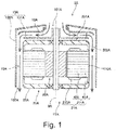
- Fig. 1 is a longitudinal section of a centrifugal blower 1A according to a first embodiment. As illustrated in Fig. 1 , the centrifugal blower 1A includes a motor 11A, an impeller 12A, and a blower casing 13A.
- the motor 11A includes a stationary portion 20A including a stator 21A and a motor cover 22A that holds the stator 21A, and a rotating portion 30A that rotates about a central axis 9A that extends vertically.
- the stator 21A includes a stator core 211A and coils 213A.
- the stator core 211A includes a toric core back 41A and a plurality of teeth 42A that extend inwards in the radial direction from the core back 41A.
- the coils 213A are formed of a conducting wire wound around the teeth 42A.
- the motor cover 22A holds the stator 21A.
- the motor cover 22A includes, above the stator 21A, an upper surface 201A that widens in a substantially perpendicular manner with respect to the central axis 9A, and a cylindrical outer peripheral surface 202A that extends downwards from an outer edge of the upper surface 201A.
- the impeller 12A is a centrifugal impeller that is disposed above the motor 11A and that rotates together with the rotating portion 30A of the motor 11A.
- the blower casing 13A houses the motor 11A and the impeller 12A.
- the blower casing 13A includes an intake port 101A, an upper side casing top plate portion 131A, and a wall portion 132A.
- the upper side casing top plate portion 131A is disposed over the impeller 12A.
- the intake port 101A is provided at the middle of the upper side casing top plate portion 131A.
- the wall portion 132A extends downwards from the upper side casing top plate portion 131A in a tubular manner.
- a flow path 10A continuous in the axial direction is formed between an inner peripheral surface of the wall portion 132A and the outer peripheral surface 202A of the motor cover 22A.
- a discharge port 102A that is in communication with an external space is formed in a lower end portion of the flow path 10A.
- the core back 41A of the stator 21A includes, in at least a portion of the outer peripheral surface, exposed portions 410A exposed to the flow path 10A.
- the rotating portion 30A of the motor 11A and the impeller 12A rotate when the centrifugal blower 1A is driven.
- a gas above the blower casing 13A is suctioned into the impeller 12A through the intake port 101A, and is discharged towards the outer side of the impeller 12A in the radial direction and below the impeller 12A.
- the gas discharged from the impeller 12A proceeds downwards inside the flow path 10A in a straight manner and is discharged to the outside through the discharge port 102A.
- the flow path 10A extending in a straight manner suppresses a decrease in the flow speed of the air inside the flow path 10A. Accordingly, a decrease in the air blowing efficiency of the centrifugal blower 1A is suppressed.
- stator core 211A being exposed to the flow path 10A in the exposed portions 410A dissipates heat generated in the stator 21A from the exposed portions 410A.
- cooling of the stator 21A can be performed efficiently. Accordingly, in the centrifugal blower 1A, the stator 21A can be cooled efficiently without decreasing the air blowing efficiency.
- Fig. 2 is a longitudinal section of a centrifugal blower 1 according to a second embodiment.
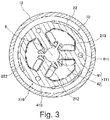
- Fig. 3 is a cross-sectional view of the centrifugal blower 1 in an area in the axial direction where a stator core 211 is disposed.
- the centrifugal blower 1 is a turbo centrifugal fan that suctions air thereabove through an intake hole provided in an upper portion, and that discharges air downwards. Compared with a sirocco centrifugal fan, the turbo centrifugal fan is higher in efficiency and is lower in noise.
- the centrifugal blower 1 of the present embodiment is, for example, provided in a vacuum cleaner and is used to generate suction force.
- the centrifugal blower of the present invention can be one that is used for applications other than a vacuum cleaner.
- the centrifugal blower may be a range hood fan, another blowing device, such as an air supply and exhaust device, used in a duct of a building, or a device that performs intake and exhaust of air and that is mounted in a household electric appliance, a medical appliance, a large piece of equipment for industrial use, or the like.
- the centrifugal blower 1 includes a motor 11, an impeller 12, and a blower casing 13.
- a later-described rotating portion 30 of the motor 11 and the impeller 12 rotate about a central axis 9.
- the motor 11 is an inner rotor brushless DC motor.
- the motor 11 includes a stationary portion 20 and the rotating portion 30.
- the stationary portion 20 relatively stops with respect to the blower casing 13.
- the rotating portion 30 is rotatably supported about the central axis 9 with respect to the stationary portion 20.
- the stationary portion 20 includes a stator 21, a motor cover 22, a bottom plate 23, a circuit board 24, an upper bearing 25, and a lower bearing 26.
- the rotating portion 30 includes a shaft 31 and a rotor 32.
- the stator 21 is an armature that generates a magnetic flux in accordance with a driving current supplied from a circuit board 24.
- the stator 21 annularly surrounds the vertically extending central axis 9. As illustrated in Figs. 2 and 3 , the stator 21 includes the stator core 211, insulators 212, and a plurality of coils 213.
- the stator core 211 is formed of a lamination steel plate in which electromagnetic steel plates are laminated in the axial direction.
- the stator core 211 includes a toric core back 41 and a plurality of teeth 42 that extend inwards in the radial direction from the core back 41.
- the core back 41 is disposed substantially coaxially with the central axis 9.
- the plurality of teeth 42 are arranged in a substantially equidistant manner in the circumferential direction.
- the insulators 212 are attached to the stator core 211.
- a resin that is an insulating material is used as the material of the insulators 212.
- the insulators 212 cover the two end faces of the teeth 42 in the axial direction and the two end faces in the circumferential direction.
- the coils 213 are each formed of a conducting wire that is wound around a corresponding one of the teeth 42 with the insulators 212 in between.
- the motor 11 of the present embodiment is a 3-phase, 3-slot motor including three teeth 42 and three coils 213.
- the number of switching of the current supplied to each phase in a single rotation can be reduced.
- the number of switching in each slot, which corresponds to a phase can be one in each of the three slots while the rotor 32 rotates once.
- the centrifugal blower 1 is used in a vacuum cleaner, and may be used in a high rotation range of about 60,000 rotations per minute. By reducing the number of slots, the number of switching does not become excessively high during high rotation, and an appropriate control can be performed.
- the motor cover 22 is a member that holds the stator 21 and the upper bearing 25. As illustrated in Fig. 2 , the motor cover 22 includes an upper plate portion 221, a lateral plate portion 222, a first fixed portion 223, a second fixed portion 224, and third fixed portions 225.
- the upper plate portion 221 is a plate-shaped region that widens above the stator 21 in a substantially perpendicular manner with respect to the central axis 9.
- the upper bearing 25 is held on the inner side of the upper plate portion 221 in the radial direction.
- the lateral plate portion 222 extends downwards in the axial direction from an outer edge of the upper plate portion 221 in a substantially cylindrical manner. Accordingly, an upper surface 201 of the motor cover 22, in other words, an upper surface of the upper plate portion 221 is, above the stator 21, substantially perpendicular to the central axis 9.
- an outer peripheral surface 202 of the motor cover 22 in other words, an outer peripheral surface of the lateral plate portion 222 extends downwards in a tubular manner from an outer edge of the upper surface of the motor cover 22.
- the lateral plate portion 222 is provided with window portions 226 that penetrate thereof in the radial direction.
- the first fixed portion 223 and the second fixed portion 224 protrude inwards in the radial direction from an inner peripheral surface of the lateral plate portion 222.
- the first fixed portion 223 is disposed above the core back 41 of the stator core 211.
- the first fixed portion 223 includes screw holes that are recessed upwards from an underside thereof.
- the second fixed portion 224 is disposed below the core back 41 of the stator core 211.
- the second fixed portion 224 includes screw holes that vertically penetrate thereof.
- the core back 41 is provided with through holes 411 that penetrate thereof in the axial direction.
- the stator 21 and the motor cover 22 are fixed to each other by fitting screws 43 in the screw holes provided in the motor cover 22, and the through holes 411.
- the screw holes of the first fixed portion 223 and the second fixed portion 224 in which the screws 43 are fitted and the through holes 411 are provided at three positions in the circumferential direction.
- the fixing positions of the stator 21 and the motor cover 22 are not limited to three positions and may be two positions, or four or more positions.
- the method of fixing the stator 21 and the motor cover 22 to each other is not limited to screw fixing.
- the stator 21 and the motor cover 22 may be fixed to each other by another method, such as press fitting or adhesion.
- the third fixed portions 225 protrude outwards in the radial direction from near a lower end portion of the lateral plate portion 222.
- the bottom plate 23 is screw fixed to the third fixed portions 225.
- the third fixed portions 225 are provided at three positions in the circumferential direction. Note that the fixing positions of the motor cover 22 and the bottom plate 23 are not limited to three positions and may be two positions, or four or more positions. Furthermore, the motor cover 22 and the bottom plate 23 may be fixed to each other by another method.
- the bottom plate 23 is a member that covers at least a portion of the opening below the motor cover 22.
- the bottom plate 23 widens in a substantially perpendicular manner with respect to the central axis 9.
- the lower bearing 26 is held at the middle of the bottom plate 23.
- the stator 21, the circuit board 24, the upper bearing 25, the lower bearing 26, and the rotor 32 are housed inside the casing constituted by the motor cover 22 and the bottom plate 23.
- the circuit board 24 is disposed below the stator 21 and substantially perpendicular to the central axis 9.
- An electronic component that constitutes an electric circuit for supplying a driving current to the coils 213 is mounted on the circuit board 24.
- An end portion of the conducting wire that constitutes the coils 213 is electrically connected to the electric circuit on the circuit board 24.
- the upper bearing 25 is a mechanism that supports the shaft 31 in a rotatable manner with respect to the motor cover 22.
- the upper bearing 25 is disposed below a lower side labyrinth portions 71 to 73 described later.
- the lower bearing 26 is a mechanism that supports the shaft 31 in a rotatable manner with respect to the bottom plate 23.
- a Ball bearing in which spherical rolling elements are interposed between an inner ring and an outer ring is used in each of the upper bearing 25 and the lower bearing 26.
- An elastic member 27 is interposed between the motor cover 22 and the upper bearing 25.
- the shaft 31 is a columnar member that is disposed along the central axis 9.
- the shaft 31 is supported by the upper bearing 25 and the lower bearing 26 and rotates about the central axis 9.
- the upper end portion of the shaft 31 protrudes above the motor cover 22, and the impeller 12 is fixed thereto.
- the impeller 12 may be indirectly fixed to the shaft 31 with another member in between.
- the rotor 32 is connected to the shaft 31 and rotates together with the shaft 31.
- the rotor 32 of the present embodiment is formed of a magnetic resin formed in a substantially cylindrical shape.
- a north pole and a south pole of magnets are alternately attached on an outer peripheral surface of the rotor 32.
- the outer peripheral surface of the rotor 32 opposes the end faces of the teeth 42 on the inner side in the radial direction with a slight gap in between in the radial direction.
- the rotor 32 includes a pole face that faces the stator 21 in the radial direction.
- the rotor 32 may be a plurality of magnets fixed to an outer peripheral surface or inside a cylindrical rotor core that is a magnetic material. Furthermore, the rotor 32 may be constituted by a single piece of magnet.
- the impeller 12 is a so-called turbo centrifugal impeller.
- the impeller 12 is disposed above the motor cover 22 of the motor 11. As illustrated in Fig. 2 , the impeller 12 includes an upper shroud 51, a lower shroud 52, and a plurality of blades 53.
- the upper shroud 51 includes a cylindrical portion 511 and an upper shroud top plate portion 512.
- the upper shroud 51 is disposed above the lower shroud 52 and the plurality of blades 53.
- the cylindrical portion 511 is a region substantially cylindrical about the central axis 9.
- the cylindrical portion 511 of the present embodiment has a substantially uniform diameter irrespective of the position in the axial direction.
- the cylindrical portion 511 may have a shape in which the diameter becomes larger towards the lower side in the axial direction.
- An intake port 101 is formed between the inner peripheral surface of the cylindrical portion 511 and an inner peripheral surface of a later-described cylindrical portion 130 of the blower casing 13. In other words, the intake port 101 is provided at the middle of the upper shroud 51.
- the upper shroud top plate portion 512 widens outwards in the radial direction from a lower end portion of the cylindrical portion 511. A position of an outer edge of the upper shroud top plate portion 512 in the radial direction is substantially the same as a position of an outer edge of the lower shroud 52 in the radial direction.
- the lower shroud 52 is a plate-shaped region that widens above the motor cover 22 in a substantially perpendicular manner with respect to the central axis 9. An underside of the lower shroud 52 opposes an upper surface of the motor cover 22 in the axial direction. An end portion of the lower shroud 52 on the inner side in the radial direction is fixed to the shaft 31 of the motor 11.
- the blades 53 are disposed between the upper shroud 51 and the lower shroud 52.
- the plurality of blades 53 are disposed in a substantially equidistant manner in the circumferential direction.
- the blower casing 13 includes an upper side casing top plate portion 131, a wall portion 132, and the cylindrical portion 130.
- the upper side casing top plate portion 131 is disposed over the impeller 12, and widens in an annular manner along an upper surface of the upper shroud 51.
- the wall portion 132 extends downwards in a tabular manner from the upper side casing top plate portion 131.
- the motor 11 and the impeller 12 are housed on the inner side of the wall portion 132 in the radial direction.
- the cylindrical portion 130 extends downwards in a cylindrical manner from an inner end of the upper side casing top plate portion 131 in the radial direction.
- the intake port 101 is formed between the inner peripheral surface of the cylindrical portion 511 of the impeller 12 and the inner peripheral surface of the cylindrical portion 130. In other words, the intake port 101 is provided at the middle of the upper side casing top plate portion 131.
- the blower casing 13 of the present embodiment is formed of three annular members, namely, an upper side casing 133, a middle casing 134, and a lower side casing 135.
- the middle casing 134 is disposed on the lower side of the upper side casing 133.
- the lower side casing 135 is disposed below the middle casing 134.
- the upper side casing 133 includes the upper side casing top plate portion 131 and an upper end of the wall portion 132.
- the middle casing 134 and the lower side casing 135 are cylindrical members that form the wall portion 132.
- the blower casing 13 of the present embodiment is formed of three members; however, the blower casing 13 may be formed of a single member or may be formed of two, or four or more members.
- An outer peripheral surface of the motor cover 22 and an inner peripheral surface of the wall portion 132 of the blower casing 13 are disposed with a space in between in the radial direction.
- the space continuous in the axial direction between the outer peripheral surface of the motor cover 22 and the inner peripheral surface of the wall portion 132 is a flow path 10 of gas when the centrifugal blower 1 is driven.
- Discharge ports 102 that are in communication with an external space is formed in lower end portions of the flow path 10. Specifically, as illustrated in Fig. 2 , discharge ports 102 are formed between a lower end portion of the wall portion 132 of the blower casing 13 and the lateral plate portion 222 of the motor cover 22 at positions in the circumferential direction where the third fixed portions 225 of the motor cover 22 are not disposed. Furthermore, discharge ports 102 are formed between the lower end portion of the wall portion 132 of the blower casing 13 and the third fixed portion 225 of the motor cover 22 at positions in the circumferential direction where the third fixed portions 225 of the motor cover 22 are not disposed.
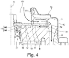
- Fig. 4 is a longitudinal section of a portion of the centrifugal blower 1.
- the gas that has been discharged from the impeller 12 flows downwards in the axial direction in a straight manner inside the flow path 10.
- the flow path 10, which is a blowing path after discharge from the impeller 12, extending downwards in a straight manner in the axial direction suppresses a decrease in the flow speed of the air inside the flow path 10. Accordingly, a decrease in the air blowing efficiency of the centrifugal blower 1 is suppressed.
- the lateral plate portion 222 of the motor cover 22 includes window portions 226. Accordingly, as illustrated in Figs. 2 and 3 , portions of an outer peripheral surface of the core back 41 of the stator core 211 become exposed portions 410 exposed to the flow path 10.
- the coils 213 When the motor 11 is driven, the coils 213 generate heat. The heat generated by the coils 213 is transmitted to the stator core 211 through the insulators 212. With the above, the entire temperature of the stator 21 increases. However, in the centrifugal blower 1, since portions of the core back 41 are exposed to the flow path 10, the core back 41 is cooled by the air flow that has occurred in the flow path 10. In other words, cooling of the stator 21 can be performed efficiently by having portions of the core back 41 be exposed to the flow path 10. As describe above, in the centrifugal blower 1, the stator 21 can be cooled efficiently without decreasing the air blowing efficiency.
- the exposed portions 410 are provided, in the core back 41, on the outer side of the teeth 42 in the radial direction.
- the areas in the core back 41 that are the closest to the coils 213 can be exposed to the flow path 10. Accordingly, the heat that has been generated in the coils 213 and that has been transmitted to the core back 41 from the teeth 42 can be efficiently dissipated to the gas inside the flow path 10. In other words, cooling of the stator 21 can be performed in a further efficient manner.
- a width of each exposed portion 410 in the circumferential direction is larger than a width of each of the teeth 42 in the circumferential direction.
- the air flow generated with the rotation of the impeller 12 flows downwards in the axial direction from the outer side of the lower shroud 52 in the radial direction along an inner surface of the blower casing 13.
- the flow path 10 inside the blower casing 13 does not widen much and extends downwards in the axial direction from near an outer end of the lower shroud 52. Accordingly, generation of a vortex inside the flow path 10 is suppressed, and the flow speed of the air oriented downwards inside the flow path 10 from the outer side of the lower shroud 52 in the radial direction does not become decreased easily. With the above, a decrease in the air blowing efficiency of the centrifugal blower 1 is suppressed further.
- a decrease in the flow rate of the gas passing inside the flow path 10 can be suppressed. Accordingly, a decrease in the efficiency of heat dissipation in the exposed portions 410 is suppressed, and cooling of the stator 21 can be performed in a further efficient manner.
- a distance between the central axis 9 and the outer peripheral surface of the motor cover 22 in the radial direction substantially coincides with a distance between the central axis 9 and an outer end of the lower shroud 52 of the impeller 12 in the radial direction.
- a position in the radial direction of the inner end of the flow path 10 in the radial direction substantially coincides with a position in the radial direction of the outer end of the lower shroud 52 of the impeller 12 in the radial direction.
- the air flow discharged from the impeller 12 does not have to flow on the inner side of the lower shroud 52 in the radial direction with respect to the outer end of the lower shroud 52 in the radial direction. Accordingly, the direction of the air flow is not bent 90° or more.
- the distance between the central axis 9 and the outer peripheral surface of the motor cover 22 in the radial direction may be longer that the distance between the central axis 9 and the outer end of the lower shroud 52 of the impeller 12 in the radial direction.
- the direction of the air flow discharged from the impeller 12 and that flows towards the flow path 10 does not have to be bent 90° or more.
- a decrease in the speed of the air flow discharged from the impeller 12 can be suppressed.
- a distance between the central axis 9 and the exposed portions 410 in the radial direction is shorter than a distance between the central axis 9 and a portion facing the flow path 10 in the outer peripheral surface of the motor cover 22 in the radial direction. Since the outer peripheral surface of the core back 41 is not smooth compared with the outer peripheral surface of the motor cover 22, the flow path resistance in the exposed portions 410 is larger. Accordingly, by widening the radial direction width of the flow path 10 near the exposed portions 410, a decrease in the speed of the air flow inside the flow path 10 is suppressed. Accordingly, a decrease in the efficiency of heat dissipation in the exposed portions 410 is suppressed, and cooling of the stator 21 can be performed in a further efficient manner.
- the window portion 226 and a portion in the lateral plate portion 222 that covers the outer peripheral surface of the core back 41 are disposed alternately in the motor cover 22.
- the motor cover 22 covers at least a portion of the outer peripheral surface of the core back 41.
- a washer 14 having a substantially T-shaped longitudinal section is in contact with the underside of the impeller 12.
- the washer 14 includes a cylindrical shaft portion 141, an inner peripheral surface of which is in contact with an outer peripheral surface of the shaft 31, and a flange portion 142 that extends outwards in the radial direction from an upper end of the shaft portion 141.
- a lower end face of the shaft portion 141 is in contact with an upper surface of the upper bearing 25.
- the washer 14 is positioned on the underside of the lower shroud 52, and is an annular contact member that is in contact with the rotating portion 30 of the motor 11.
- An underside of the flange portion 142 of the washer 14 and the upper surface of the motor cover 22 oppose each other in the axial direction with the lower side axial direction gap 70 in between.
- the motor cover 22 includes three annular motor projection portions 61, 62, and 63 that protrude upwards from the upper surface of the motor cover 22.
- the three motor projection portions 61, 62, and 63 are arranged in the radial direction.
- a first lower side labyrinth portion 71 is formed between the first motor projection portion 61 that is, among the three motor projection portions 61, 62, and 63, disposed on the outermost side in the radial direction and the underside of the lower shroud 52.
- a second lower side labyrinth portion 72 is formed between the second motor projection portion 62 disposed inside the first motor projection portion 61 in the radial direction and outside the third motor projection portion 63 in the radial direction, and the underside of the lower shroud 52.
- a third lower side labyrinth portion 73 is formed between the third motor projection portion 63 that is, among the three motor projection portions 61, 62, and 63, disposed on the innermost side in the radial direction and the underside of the flange portion 142 of the washer 14.
- the lower side axial direction gap 70 includes three lower side labyrinth portions 71, 72, and 73 in which the widths in the axial direction become partially narrow.
- the motor projection portions 61, 62, and 63 serving as projection portions are provided not on the impeller 12 side, the impeller 12 serving as a body of rotation, but on the motor cover 22 side, the motor cover 22 serving as a stationary member.
- the load such as centrifugal force, acting on the impeller 12 can be reduced.
- the lower side labyrinth portions may be formed by providing projection portions on the underside of the lower shroud 52 of the impeller 12.
- three lower side labyrinth portions 71, 72, and 73 are provided in the lower side axial direction gap 70.
- the lower side axial direction gap 70 have three or more lower side labyrinth portions therein, leaking of the air flow can be suppressed further.
- the suction power becomes high in the range in which the rotation speed of the motor 11 is low (5000 rotation per minute, for example), in the range in which the rotation speed is high (60,000 rotations per minute, for example), no significant improvement in the suction power is seen.
- the suction power also improves in the range in which the rotation speed of the motor 11 is high.
- the centrifugal blower 1 is used in a vacuum cleaner, and is used in a high rotation range of about 60,000 rotations per minute. Accordingly, it is desirable that three or more lower side labyrinth portions be provided in the lower side axial direction gap 70.
- the first motor projection portion on the outermost side 61 is disposed in substantially the middle of the central axis 9 and the inner peripheral surface of the blower casing 13.
- the motor projection portions provided on the upper surface of the motor cover 22 are, desirably, disposed on the inner side in the radial direction with respect to a middle point between the central axis 9 and the inner peripheral surface of the blower casing 13 in the radial direction.
- the third lower side labyrinth portion 73 is disposed below the first lower side labyrinth portion 71 and the second lower side labyrinth portion 72 in the axial direction.
- the third lower side labyrinth portion 73 disposed, among lower side labyrinth portions 71, 72, and 73, on the innermost side in the radial direction is, in the axial direction, disposed below the first lower side labyrinth portion 71 disposed on the outermost side in the radial direction.
- one of the plurality of lower side labyrinth portions 71, 72, and 73 has a height in the axial direction that is different from that of another one of the plurality of lower side labyrinth portions 71, 72, and 73.
- the length of the first lower side labyrinth portion 71 in the radial direction is longer than the length of the second lower side labyrinth portion 72 in the radial direction and the length of the third lower side labyrinth portion 73 in the radial direction.
- one of the length of the plurality of lower side labyrinth portions 71, 72, and 73 in the radial direction is longer than the length of another one of the plurality of lower side labyrinth portions 71, 72, and 73 in the radial direction.
- the first lower side labyrinth portion 71 on the outermost side in the radial direction is long.
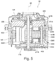
- Fig. 5 is a longitudinal section of a centrifugal blower 1B according to a third embodiment.
- Fig. 6 is a side view of a motor 11B and an impeller 12B of the centrifugal blower 1B.
- Fig. 7 is a cross-sectional view of the centrifugal blower 1B in an area in the axial direction where a stator core 211B and stator blades 80B are disposed.
- the centrifugal blower 1B has a structure that is similar to that of the centrifugal blower 1 of the second embodiment.
- points that are different from the centrifugal blower 1 according to the second embodiment will be described.
- the motor cover 22B includes the plurality of stator blades 80B.
- the stator blades 80B protrude from a lateral plate portion 222B towards an outer side in the radial direction, and are disposed inside a flow path 10B. Furthermore, the stator blades 80B are disposed so as to be spaced apart from each other in the circumferential direction and in a substantially equidistance in the circumferential direction.
- the motor cover 22B includes a window portion 226B continuing in an annular manner.
- the motor cover 22B is constituted by two members, namely, an upper side motor cover 227B and a lower side motor cover 228B that are separated by the window portion 226B.
- the upper side motor cover 227B includes an upper plate portion 221B, a portion of the lateral plate portion 222B that is disposed on an upper side of the window portion 226B, a first fixed portion 223B, and the stator blades 80B.
- the lower side motor cover 228B includes a portion of the lateral plate portion 222B that is disposed on a lower side of the window portion 226B, a second fixed portion 224B, and a third fixed portions 225B.
- the window portion 226B is disposed in the entire circumferential direction. Furthermore, lower end portions of the stator blades 80B are disposed between an upper end portion and a lower end portion of the window portion 226B. With the above, in the lower sides of the stator blades 80B, an exposed portion 410B is provided in the entire circumference of an outer peripheral surface of a core back 41B of the stator core 211B. Furthermore, in the area in the axial direction where the stator core 211B and the stator blades 80B are both disposed, as illustrated in Fig. 7 , a stator blade 80B and an exposed portion 410B are disposed alternately in the circumferential direction. In other words, the exposed portion 410B is disposed between the stator blades 80B that are adjacent to each other in the circumferential direction.
- the upper side motor cover 227B and the lower side motor cover 228B may be connected members that are connected into one at portions in the circumferential direction.
- the stator blades 80B may be extended below the window portion 226B, and the upper side motor cover 227B and the lower side motor cover 228B may be connected through the stator blades 80B.
- a distance in the radial direction between a central axis 9B and an outer end of the exposed portion 410B in the radial direction substantially coincides with a distance in the radial direction between the central axis 9B and an outer end of a lower shroud 52B of the impeller 12B in the radial direction.
- the distance in the radial direction between the central axis 9B and the outer end of the exposed portion 410B in the radial direction may be longer than the distance in the radial direction between the central axis 9 and the outer end of the lower shroud 52B of the impeller 12B in the radial direction.
- the air flow discharged from the impeller 12B can be in contact with the exposed portion 410B without flowing on the inner side of the lower shroud 52B in the radial direction with respect to the outer end of the lower shroud 52B in the radial direction.
- a distance between the central axis 9B and the outer peripheral surface of the motor cover 22B in the radial direction substantially coincides with a distance between the central axis 9B and an outer end of the lower shroud 52B of the impeller 12B in the radial direction.
- an outer peripheral surface of the lateral plate portion 222B and an outer peripheral surface of a stator 21B constituting the flow path 10B are disposed on the same cylindrical surface.
- the exposed portion of the stator core extended from the upper end to the lower end of the outer peripheral surface of the core back.
- the exposed portion may be disposed in only a portion of the outer peripheral surface of the core back in the axial direction.
- stator blades extend from the inner end of the flow path in the radial direction to the outer end in the radial direction.
- stator blades may be disposed in a partial area in the flow path in the radial direction.
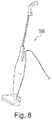
- Fig. 8 is a perspective view of a vacuum cleaner 100.
- the vacuum cleaner 100 includes the centrifugal blower described above. With the above, the stator of the centrifugal blower mounted in the vacuum cleaner 100 can be cooled efficiently without decrease in the air blowing efficiency of the vacuum cleaner 100.
- the present invention can be used in a centrifugal blower and in a vacuum cleaner.
- Reference Signs List
Landscapes
- Engineering & Computer Science (AREA)
- Mechanical Engineering (AREA)
- General Engineering & Computer Science (AREA)
- Power Engineering (AREA)
- Physics & Mathematics (AREA)
- Thermal Sciences (AREA)
- Structures Of Non-Positive Displacement Pumps (AREA)
- Electric Suction Cleaners (AREA)
Abstract
Description
- The present invention relates to a centrifugal blower and a vacuum cleaner.
- Conventionally, a centrifugal blower is used in high-output blowing devices, such as a vacuum cleaner and an air intake and exhaust device. The centrifugal blower includes a motor that generates driving power, an impeller that sends air, and a blower casing that houses the motor and the impeller. A conventional centrifugal blower is described in Japanese Unexamined Patent Application Publication No.
2015-59507 - In recent years, there is a need for higher output and higher efficiency of centrifugal blowers. In high-output blowing devices, since the rotation speed is high and a large amount of heat is generated by the stator serving as an armature, the stator needs to be cooled efficiently. In a centrifugal blower in Japanese Unexamined Patent Application Publication No.
2015-59507 Fig. 1 ).
PTL 1: Japanese Unexamined Patent Application Publication No.2015-59507 - However, in the structure of the centrifugal blower in Japanese Unexamined Patent Application Publication No.
2015-59507 - An object of the present invention is to provide a technique that is capable of efficiently cooling the stator without decreasing the air blowing efficiency of the centrifugal blower.
- An exemplary first invention of the present application is a centrifugal blower including a stationary portion that includes a stator and a motor cover that holds the stator, a motor that includes a rotating portion that rotate about a vertically extending central axis, a centrifugal impeller that is disposed above the motor and that rotates together with the rotating portion, and a blower casing that houses therein the motor and the impeller. In the centrifugal blower, the stator includes a stator core that includes a toric core back and a plurality of teeth that extend inwards in a radial direction, a coil is formed of a conductive wire wound around the teeth, the motor cover includes an upper surface above the stator, the upper surface widening in a substantially perpendicular manner with respect to the central axis, and a cylindrical outer peripheral surface that extends downwards from an outer edge of the upper surface, the blower casing includes an intake port, an upper side casing top plate portion disposed above the impeller, the intake port being disposed at a middle of the upper side casing top plate portion, and a cylindrical wall portion that extend downwards from the upper side casing top plate portion to an outer side of the motor cover in the radial direction, a flow path continuous in the axial direction is constituted by an inner peripheral surface of the wall portion and the outer peripheral surface of the motor cover, a discharge port in communication with an external space is provided at a lower end portion of the flow path, and the core back includes an exposed portion exposed to the flow path in at least a portion of the outer peripheral surface of the core back.
- According to the exemplary first invention of the present application, the stator can be cooled efficiently without decreasing the air blowing efficiency of the centrifugal blower.
-
- [
Fig. 1] Fig. 1 is a longitudinal section of a centrifugal blower according to a first embodiment. - [
Fig. 2] Fig. 2 is a longitudinal section of a centrifugal blower according to a second embodiment. - [
Fig. 3] Fig. 3 is a cross-sectional view of the centrifugal blower according to the second embodiment. - [
Fig. 4] Fig. 4 is a longitudinal section of a portion of the centrifugal blower according to the second embodiment. - [
Fig. 5] Fig. 5 is a longitudinal section of a centrifugal blower according to a third embodiment. - [
Fig. 6] Fig. 6 is a side view of a motor and an impeller according to the third embodiment. - [
Fig. 7] Fig. 7 is a cross-sectional view of the centrifugal blower according to the third embodiment. - [
Fig. 8] Fig. 8 is a perspective view of a vacuum cleaner. - Hereinafter, exemplary embodiments of the present invention will be described with reference to the drawings. Note that in the present application, a direction parallel to a central axis of a centrifugal blower is referred to as an "axial direction", a direction orthogonal to the central axis of the centrifugal blower is referred to as a "radial direction", and a direction along a circumference extending about a center of the central axis of the centrifugal blower is referred to as a "circumferential direction". Furthermore, in the present application, shapes and positional relationships of parts are described while the axial direction is an up-down direction, and an impeller side with respect to a motor is an upper side. However, the definition of the up-down direction is not intended to limit the orientations of the centrifugal blower while manufacturing and while in use.
-
Fig. 1 is a longitudinal section of acentrifugal blower 1A according to a first embodiment. As illustrated inFig. 1 , thecentrifugal blower 1A includes amotor 11A, animpeller 12A, and ablower casing 13A. - The
motor 11A includes astationary portion 20A including astator 21A and amotor cover 22A that holds thestator 21A, and a rotatingportion 30A that rotates about acentral axis 9A that extends vertically. - The
stator 21A includes astator core 211A andcoils 213A. Thestator core 211A includes atoric core back 41A and a plurality ofteeth 42A that extend inwards in the radial direction from thecore back 41A. Thecoils 213A are formed of a conducting wire wound around theteeth 42A. - The
motor cover 22A holds thestator 21A. Themotor cover 22A includes, above thestator 21A, anupper surface 201A that widens in a substantially perpendicular manner with respect to thecentral axis 9A, and a cylindrical outerperipheral surface 202A that extends downwards from an outer edge of theupper surface 201A. - The
impeller 12A is a centrifugal impeller that is disposed above themotor 11A and that rotates together with the rotatingportion 30A of themotor 11A. - The
blower casing 13A houses themotor 11A and theimpeller 12A. Theblower casing 13A includes anintake port 101A, an upper side casingtop plate portion 131A, and awall portion 132A. The upper side casingtop plate portion 131A is disposed over theimpeller 12A. Furthermore, theintake port 101A is provided at the middle of the upper side casingtop plate portion 131A. On the outer side of themotor cover 22A in the radial direction, thewall portion 132A extends downwards from the upper side casingtop plate portion 131A in a tubular manner. - In the
centrifugal blower 1A, aflow path 10A continuous in the axial direction is formed between an inner peripheral surface of thewall portion 132A and the outerperipheral surface 202A of themotor cover 22A. Adischarge port 102A that is in communication with an external space is formed in a lower end portion of theflow path 10A. Furthermore, thecore back 41A of thestator 21A includes, in at least a portion of the outer peripheral surface, exposedportions 410A exposed to theflow path 10A. - The rotating
portion 30A of themotor 11A and theimpeller 12A rotate when thecentrifugal blower 1A is driven. When theimpeller 12A rotates, as depicted by solid line arrows inFig. 1 , a gas above theblower casing 13A is suctioned into theimpeller 12A through theintake port 101A, and is discharged towards the outer side of theimpeller 12A in the radial direction and below theimpeller 12A. - The gas discharged from the
impeller 12A proceeds downwards inside theflow path 10A in a straight manner and is discharged to the outside through thedischarge port 102A. Theflow path 10A extending in a straight manner suppresses a decrease in the flow speed of the air inside theflow path 10A. Accordingly, a decrease in the air blowing efficiency of thecentrifugal blower 1A is suppressed. - Meanwhile, the
stator core 211A being exposed to theflow path 10A in the exposedportions 410A dissipates heat generated in thestator 21A from the exposedportions 410A. With the above, cooling of thestator 21A can be performed efficiently. Accordingly, in thecentrifugal blower 1A, thestator 21A can be cooled efficiently without decreasing the air blowing efficiency. -
Fig. 2 is a longitudinal section of a centrifugal blower 1 according to a second embodiment.Fig. 3 is a cross-sectional view of the centrifugal blower 1 in an area in the axial direction where astator core 211 is disposed. The centrifugal blower 1 is a turbo centrifugal fan that suctions air thereabove through an intake hole provided in an upper portion, and that discharges air downwards. Compared with a sirocco centrifugal fan, the turbo centrifugal fan is higher in efficiency and is lower in noise. - The centrifugal blower 1 of the present embodiment is, for example, provided in a vacuum cleaner and is used to generate suction force. However, the centrifugal blower of the present invention can be one that is used for applications other than a vacuum cleaner. For example, the centrifugal blower may be a range hood fan, another blowing device, such as an air supply and exhaust device, used in a duct of a building, or a device that performs intake and exhaust of air and that is mounted in a household electric appliance, a medical appliance, a large piece of equipment for industrial use, or the like.
- As illustrated in
Fig. 2 , the centrifugal blower 1 includes amotor 11, animpeller 12, and ablower casing 13. A later-describedrotating portion 30 of themotor 11 and theimpeller 12 rotate about acentral axis 9. - The
motor 11 is an inner rotor brushless DC motor. Themotor 11 includes astationary portion 20 and the rotatingportion 30. Thestationary portion 20 relatively stops with respect to theblower casing 13. The rotatingportion 30 is rotatably supported about thecentral axis 9 with respect to thestationary portion 20. - The
stationary portion 20 includes astator 21, amotor cover 22, abottom plate 23, acircuit board 24, anupper bearing 25, and alower bearing 26. The rotatingportion 30 includes ashaft 31 and arotor 32. - The
stator 21 is an armature that generates a magnetic flux in accordance with a driving current supplied from acircuit board 24. Thestator 21 annularly surrounds the vertically extendingcentral axis 9. As illustrated inFigs. 2 and3 , thestator 21 includes thestator core 211,insulators 212, and a plurality ofcoils 213. - The
stator core 211 is formed of a lamination steel plate in which electromagnetic steel plates are laminated in the axial direction. Thestator core 211 includes a toric core back 41 and a plurality ofteeth 42 that extend inwards in the radial direction from the core back 41. The core back 41 is disposed substantially coaxially with thecentral axis 9. The plurality ofteeth 42 are arranged in a substantially equidistant manner in the circumferential direction. - The
insulators 212 are attached to thestator core 211. A resin that is an insulating material is used as the material of theinsulators 212. Theinsulators 212 cover the two end faces of theteeth 42 in the axial direction and the two end faces in the circumferential direction. Thecoils 213 are each formed of a conducting wire that is wound around a corresponding one of theteeth 42 with theinsulators 212 in between. - As illustrated in
Fig. 3 , themotor 11 of the present embodiment is a 3-phase, 3-slot motor including threeteeth 42 and threecoils 213. By reducing the number of slots in the above manner, the number of switching of the current supplied to each phase in a single rotation can be reduced. In other words, the number of switching in each slot, which corresponds to a phase, can be one in each of the three slots while therotor 32 rotates once. The centrifugal blower 1 is used in a vacuum cleaner, and may be used in a high rotation range of about 60,000 rotations per minute. By reducing the number of slots, the number of switching does not become excessively high during high rotation, and an appropriate control can be performed. - The
motor cover 22 is a member that holds thestator 21 and theupper bearing 25. As illustrated inFig. 2 , themotor cover 22 includes anupper plate portion 221, alateral plate portion 222, a first fixedportion 223, a second fixedportion 224, and thirdfixed portions 225. - The
upper plate portion 221 is a plate-shaped region that widens above thestator 21 in a substantially perpendicular manner with respect to thecentral axis 9. Theupper bearing 25 is held on the inner side of theupper plate portion 221 in the radial direction. Thelateral plate portion 222 extends downwards in the axial direction from an outer edge of theupper plate portion 221 in a substantially cylindrical manner. Accordingly, anupper surface 201 of themotor cover 22, in other words, an upper surface of theupper plate portion 221 is, above thestator 21, substantially perpendicular to thecentral axis 9. Furthermore, an outerperipheral surface 202 of themotor cover 22, in other words, an outer peripheral surface of thelateral plate portion 222 extends downwards in a tubular manner from an outer edge of the upper surface of themotor cover 22. Thelateral plate portion 222 is provided withwindow portions 226 that penetrate thereof in the radial direction. - The first fixed
portion 223 and the second fixedportion 224 protrude inwards in the radial direction from an inner peripheral surface of thelateral plate portion 222. The first fixedportion 223 is disposed above the core back 41 of thestator core 211. The first fixedportion 223 includes screw holes that are recessed upwards from an underside thereof. The second fixedportion 224 is disposed below the core back 41 of thestator core 211. The second fixedportion 224 includes screw holes that vertically penetrate thereof. - The core back 41 is provided with through
holes 411 that penetrate thereof in the axial direction. Thestator 21 and themotor cover 22 are fixed to each other by fittingscrews 43 in the screw holes provided in themotor cover 22, and the throughholes 411. - In the
motor 11 of the present embodiment, the screw holes of the first fixedportion 223 and the second fixedportion 224 in which thescrews 43 are fitted and the throughholes 411 are provided at three positions in the circumferential direction. Note that the fixing positions of thestator 21 and themotor cover 22 are not limited to three positions and may be two positions, or four or more positions. Furthermore, the method of fixing thestator 21 and themotor cover 22 to each other is not limited to screw fixing. Thestator 21 and themotor cover 22 may be fixed to each other by another method, such as press fitting or adhesion. - The third
fixed portions 225 protrude outwards in the radial direction from near a lower end portion of thelateral plate portion 222. Thebottom plate 23 is screw fixed to the thirdfixed portions 225. In themotor 11 of the present embodiment, the thirdfixed portions 225 are provided at three positions in the circumferential direction. Note that the fixing positions of themotor cover 22 and thebottom plate 23 are not limited to three positions and may be two positions, or four or more positions. Furthermore, themotor cover 22 and thebottom plate 23 may be fixed to each other by another method. - The
bottom plate 23 is a member that covers at least a portion of the opening below themotor cover 22. Thebottom plate 23 widens in a substantially perpendicular manner with respect to thecentral axis 9. Thelower bearing 26 is held at the middle of thebottom plate 23. Thestator 21, thecircuit board 24, theupper bearing 25, thelower bearing 26, and therotor 32 are housed inside the casing constituted by themotor cover 22 and thebottom plate 23. - The
circuit board 24 is disposed below thestator 21 and substantially perpendicular to thecentral axis 9. An electronic component that constitutes an electric circuit for supplying a driving current to thecoils 213 is mounted on thecircuit board 24. An end portion of the conducting wire that constitutes thecoils 213 is electrically connected to the electric circuit on thecircuit board 24. - The
upper bearing 25 is a mechanism that supports theshaft 31 in a rotatable manner with respect to themotor cover 22. Theupper bearing 25 is disposed below a lowerside labyrinth portions 71 to 73 described later. Thelower bearing 26 is a mechanism that supports theshaft 31 in a rotatable manner with respect to thebottom plate 23. A Ball bearing in which spherical rolling elements are interposed between an inner ring and an outer ring is used in each of theupper bearing 25 and thelower bearing 26. - An
elastic member 27 is interposed between themotor cover 22 and theupper bearing 25. With the above, vibration during rotation of themotor 11 and theimpeller 12 can be reduced. - The
shaft 31 is a columnar member that is disposed along thecentral axis 9. Theshaft 31 is supported by theupper bearing 25 and thelower bearing 26 and rotates about thecentral axis 9. The upper end portion of theshaft 31 protrudes above themotor cover 22, and theimpeller 12 is fixed thereto. In the present embodiment, while theimpeller 12 is directly fixed to theshaft 31, theimpeller 12 may be indirectly fixed to theshaft 31 with another member in between. - The
rotor 32 is connected to theshaft 31 and rotates together with theshaft 31. Therotor 32 of the present embodiment is formed of a magnetic resin formed in a substantially cylindrical shape. A north pole and a south pole of magnets are alternately attached on an outer peripheral surface of therotor 32. Furthermore, the outer peripheral surface of therotor 32 opposes the end faces of theteeth 42 on the inner side in the radial direction with a slight gap in between in the radial direction. In other words, therotor 32 includes a pole face that faces thestator 21 in the radial direction. - Note that in the present embodiment, while the
rotor 32 formed of magnetic resin is used, therotor 32 may be a plurality of magnets fixed to an outer peripheral surface or inside a cylindrical rotor core that is a magnetic material. Furthermore, therotor 32 may be constituted by a single piece of magnet. - When the
motor 11 is driven, a driving current is supplied to thecoils 213 from the electric circuit on thecircuit board 24, and a magnetic flux is generated in the plurality ofteeth 42 of thestator core 211. With the above, a torque in the circumferential direction is generated through the effect of the magnetic flux between theteeth 42 and therotor 32. As a result, the rotatingportion 30 rotates about thecentral axis 9. Furthermore, together with the rotation of the rotatingportion 30, theimpeller 12 rotates. - The
impeller 12 is a so-called turbo centrifugal impeller. Theimpeller 12 is disposed above themotor cover 22 of themotor 11. As illustrated inFig. 2 , theimpeller 12 includes anupper shroud 51, alower shroud 52, and a plurality ofblades 53. - The
upper shroud 51 includes acylindrical portion 511 and an upper shroudtop plate portion 512. Theupper shroud 51 is disposed above thelower shroud 52 and the plurality ofblades 53. - The
cylindrical portion 511 is a region substantially cylindrical about thecentral axis 9. Thecylindrical portion 511 of the present embodiment has a substantially uniform diameter irrespective of the position in the axial direction. Note that thecylindrical portion 511 may have a shape in which the diameter becomes larger towards the lower side in the axial direction. Anintake port 101 is formed between the inner peripheral surface of thecylindrical portion 511 and an inner peripheral surface of a later-describedcylindrical portion 130 of theblower casing 13. In other words, theintake port 101 is provided at the middle of theupper shroud 51. - The upper shroud
top plate portion 512 widens outwards in the radial direction from a lower end portion of thecylindrical portion 511. A position of an outer edge of the upper shroudtop plate portion 512 in the radial direction is substantially the same as a position of an outer edge of thelower shroud 52 in the radial direction. - The
lower shroud 52 is a plate-shaped region that widens above themotor cover 22 in a substantially perpendicular manner with respect to thecentral axis 9. An underside of thelower shroud 52 opposes an upper surface of themotor cover 22 in the axial direction. An end portion of thelower shroud 52 on the inner side in the radial direction is fixed to theshaft 31 of themotor 11. - The
blades 53 are disposed between theupper shroud 51 and thelower shroud 52. The plurality ofblades 53 are disposed in a substantially equidistant manner in the circumferential direction. When the centrifugal blower 1 is driven, gas between theupper shroud 51 and thelower shroud 52 is accelerated towards the outer side in the radial direction with the plurality ofblades 53. - The
blower casing 13 includes an upper side casingtop plate portion 131, awall portion 132, and thecylindrical portion 130. The upper side casingtop plate portion 131 is disposed over theimpeller 12, and widens in an annular manner along an upper surface of theupper shroud 51. On the outer side of themotor 11 in the radial direction, thewall portion 132 extends downwards in a tabular manner from the upper side casingtop plate portion 131. Themotor 11 and theimpeller 12 are housed on the inner side of thewall portion 132 in the radial direction. Thecylindrical portion 130 extends downwards in a cylindrical manner from an inner end of the upper side casingtop plate portion 131 in the radial direction. Theintake port 101 is formed between the inner peripheral surface of thecylindrical portion 511 of theimpeller 12 and the inner peripheral surface of thecylindrical portion 130. In other words, theintake port 101 is provided at the middle of the upper side casingtop plate portion 131. - The
blower casing 13 of the present embodiment is formed of three annular members, namely, anupper side casing 133, amiddle casing 134, and alower side casing 135. Themiddle casing 134 is disposed on the lower side of theupper side casing 133. Furthermore, thelower side casing 135 is disposed below themiddle casing 134. Theupper side casing 133 includes the upper side casingtop plate portion 131 and an upper end of thewall portion 132. Themiddle casing 134 and thelower side casing 135 are cylindrical members that form thewall portion 132. Theblower casing 13 of the present embodiment is formed of three members; however, theblower casing 13 may be formed of a single member or may be formed of two, or four or more members. - An outer peripheral surface of the
motor cover 22 and an inner peripheral surface of thewall portion 132 of theblower casing 13 are disposed with a space in between in the radial direction. The space continuous in the axial direction between the outer peripheral surface of themotor cover 22 and the inner peripheral surface of thewall portion 132 is aflow path 10 of gas when the centrifugal blower 1 is driven. -
Discharge ports 102 that are in communication with an external space is formed in lower end portions of theflow path 10. Specifically, as illustrated inFig. 2 , dischargeports 102 are formed between a lower end portion of thewall portion 132 of theblower casing 13 and thelateral plate portion 222 of themotor cover 22 at positions in the circumferential direction where the thirdfixed portions 225 of themotor cover 22 are not disposed. Furthermore, dischargeports 102 are formed between the lower end portion of thewall portion 132 of theblower casing 13 and the thirdfixed portion 225 of themotor cover 22 at positions in the circumferential direction where the thirdfixed portions 225 of themotor cover 22 are not disposed. - Referring to
Figs. 2 to 4 , a flow of the air flow when the centrifugal blower 1 is driven will be described next.Fig. 4 is a longitudinal section of a portion of the centrifugal blower 1. - When the centrifugal blower 1 is driven, a driving current is supplied to the
stator 21 of themotor 11, and the rotatingportion 30 of themotor 11 and theimpeller 12 rotate. When theimpeller 12 rotates, as illustrated by solid line arrows inFigs. 2 and4 , gas above theblower casing 13 is suctioned through theintake port 101, passes between theupper shroud 51 and thelower shroud 52, and is discharged towards the outer side of theimpeller 12 in the radial direction. - The gas that has been discharged towards the outer side of the
impeller 12 in the radial direction impinges against thewall portion 132 of theblower casing 13, as illustrated inFig. 2 , changes to a downward direction, and proceeds downwards in the axial direction inside theflow path 10 formed between the outer peripheral surface of themotor cover 22 and the inner peripheral surface of thewall portion 132. Furthermore, the air flow is discharged external to the centrifugal blower 1 from thedischarge port 102 at a lower end portion of theflow path 10. - As described above, in the centrifugal blower 1, the gas that has been discharged from the
impeller 12 flows downwards in the axial direction in a straight manner inside theflow path 10. Theflow path 10, which is a blowing path after discharge from theimpeller 12, extending downwards in a straight manner in the axial direction suppresses a decrease in the flow speed of the air inside theflow path 10. Accordingly, a decrease in the air blowing efficiency of the centrifugal blower 1 is suppressed. - Meanwhile, as described above, the
lateral plate portion 222 of themotor cover 22 includeswindow portions 226. Accordingly, as illustrated inFigs. 2 and3 , portions of an outer peripheral surface of the core back 41 of thestator core 211 becomeexposed portions 410 exposed to theflow path 10. - When the
motor 11 is driven, thecoils 213 generate heat. The heat generated by thecoils 213 is transmitted to thestator core 211 through theinsulators 212. With the above, the entire temperature of thestator 21 increases. However, in the centrifugal blower 1, since portions of the core back 41 are exposed to theflow path 10, the core back 41 is cooled by the air flow that has occurred in theflow path 10. In other words, cooling of thestator 21 can be performed efficiently by having portions of the core back 41 be exposed to theflow path 10. As describe above, in the centrifugal blower 1, thestator 21 can be cooled efficiently without decreasing the air blowing efficiency. - As illustrated in
Fig. 3 , the exposedportions 410 are provided, in the core back 41, on the outer side of theteeth 42 in the radial direction. With the above, the areas in the core back 41 that are the closest to thecoils 213 can be exposed to theflow path 10. Accordingly, the heat that has been generated in thecoils 213 and that has been transmitted to the core back 41 from theteeth 42 can be efficiently dissipated to the gas inside theflow path 10. In other words, cooling of thestator 21 can be performed in a further efficient manner. - Furthermore, a width of each exposed
portion 410 in the circumferential direction is larger than a width of each of theteeth 42 in the circumferential direction. With the above, the heat that has been generated in thecoils 213 and that has been transmitted to the core back 41 from theteeth 42 can be dissipated in a further efficient manner. In other words, cooling of thestator 21 can be performed in a further efficient manner. - When the centrifugal blower 1 is driven, the air flow generated with the rotation of the
impeller 12 flows downwards in the axial direction from the outer side of thelower shroud 52 in the radial direction along an inner surface of theblower casing 13. In the above, theflow path 10 inside theblower casing 13 does not widen much and extends downwards in the axial direction from near an outer end of thelower shroud 52. Accordingly, generation of a vortex inside theflow path 10 is suppressed, and the flow speed of the air oriented downwards inside theflow path 10 from the outer side of thelower shroud 52 in the radial direction does not become decreased easily. With the above, a decrease in the air blowing efficiency of the centrifugal blower 1 is suppressed further. Furthermore, a decrease in the flow rate of the gas passing inside theflow path 10 can be suppressed. Accordingly, a decrease in the efficiency of heat dissipation in the exposedportions 410 is suppressed, and cooling of thestator 21 can be performed in a further efficient manner. - As illustrated in
Fig. 2 , a distance between thecentral axis 9 and the outer peripheral surface of themotor cover 22 in the radial direction substantially coincides with a distance between thecentral axis 9 and an outer end of thelower shroud 52 of theimpeller 12 in the radial direction. In other words, except for around thewindow portions 226 at least, a position in the radial direction of the inner end of theflow path 10 in the radial direction substantially coincides with a position in the radial direction of the outer end of thelower shroud 52 of theimpeller 12 in the radial direction. - Accordingly, the air flow discharged from the
impeller 12 does not have to flow on the inner side of thelower shroud 52 in the radial direction with respect to the outer end of thelower shroud 52 in the radial direction. Accordingly, the direction of the air flow is not bent 90° or more. With the above, when the air flow discharged from theimpeller 12 flows towards theflow path 10, a decrease in the speed can be suppressed. In other words, a decrease in the air blowing efficiency of the centrifugal blower 1 can be suppressed further, and cooling of thestator 21 can be performed in a further efficient manner. - Note that the distance between the
central axis 9 and the outer peripheral surface of themotor cover 22 in the radial direction may be longer that the distance between thecentral axis 9 and the outer end of thelower shroud 52 of theimpeller 12 in the radial direction. In such a case as well, the direction of the air flow discharged from theimpeller 12 and that flows towards theflow path 10 does not have to be bent 90° or more. In such a case as well, a decrease in the speed of the air flow discharged from theimpeller 12 can be suppressed. - Furthermore, as illustrated in
Figs. 2 and3 , a distance between thecentral axis 9 and the exposedportions 410 in the radial direction is shorter than a distance between thecentral axis 9 and a portion facing theflow path 10 in the outer peripheral surface of themotor cover 22 in the radial direction. Since the outer peripheral surface of the core back 41 is not smooth compared with the outer peripheral surface of themotor cover 22, the flow path resistance in the exposedportions 410 is larger. Accordingly, by widening the radial direction width of theflow path 10 near the exposedportions 410, a decrease in the speed of the air flow inside theflow path 10 is suppressed. Accordingly, a decrease in the efficiency of heat dissipation in the exposedportions 410 is suppressed, and cooling of thestator 21 can be performed in a further efficient manner. - In the present embodiment, as illustrated in
Fig. 3 , in the area in the axial direction where thestator core 211 is disposed, thewindow portion 226 and a portion in thelateral plate portion 222 that covers the outer peripheral surface of the core back 41 are disposed alternately in themotor cover 22. In other words, themotor cover 22 covers at least a portion of the outer peripheral surface of the core back 41. As described above, by providing portions that cover the core back 41 in themotor cover 22, the fixing strength between themotor cover 22 and the core back 41 is improved. - The underside of the
lower shroud 52 of theimpeller 12 and the upper surface of themotor cover 22 oppose each other in the axial direction with a lower sideaxial direction gap 70 in between. As illustrated inFig. 4 , awasher 14 having a substantially T-shaped longitudinal section is in contact with the underside of theimpeller 12. Thewasher 14 includes a cylindrical shaft portion 141, an inner peripheral surface of which is in contact with an outer peripheral surface of theshaft 31, and aflange portion 142 that extends outwards in the radial direction from an upper end of the shaft portion 141. A lower end face of the shaft portion 141 is in contact with an upper surface of theupper bearing 25. In other words, thewasher 14 is positioned on the underside of thelower shroud 52, and is an annular contact member that is in contact with the rotatingportion 30 of themotor 11. An underside of theflange portion 142 of thewasher 14 and the upper surface of themotor cover 22 oppose each other in the axial direction with the lower sideaxial direction gap 70 in between. - The
motor cover 22 includes three annularmotor projection portions motor cover 22. The threemotor projection portions - A first lower
side labyrinth portion 71 is formed between the firstmotor projection portion 61 that is, among the threemotor projection portions lower shroud 52. A second lowerside labyrinth portion 72 is formed between the secondmotor projection portion 62 disposed inside the firstmotor projection portion 61 in the radial direction and outside the thirdmotor projection portion 63 in the radial direction, and the underside of thelower shroud 52. Furthermore, a third lowerside labyrinth portion 73 is formed between the thirdmotor projection portion 63 that is, among the threemotor projection portions flange portion 142 of thewasher 14. - As described above, the lower side
axial direction gap 70 includes three lowerside labyrinth portions axial direction gap 70 in the radial direction from the outer side of theimpeller 12 in the radial direction and from the blowing path, which extends along the outer peripheral surface of themotor 11 and towards the inside offlow path 10, can be suppressed. As a result, a decrease in the flow rate of the gas passing inside theflow path 10 can be suppressed. Accordingly, a decrease in the efficiency of heat dissipation in the exposedportions 410 is suppressed, and cooling of thestator 21 can be performed in a further efficient manner. - In the present embodiment, in order to form the lower
side labyrinth portions motor projection portions impeller 12 side, theimpeller 12 serving as a body of rotation, but on themotor cover 22 side, themotor cover 22 serving as a stationary member. With the above, compared with a case in which the projection portions are provided on the underside of thelower shroud 52 of theimpeller 12, the load, such as centrifugal force, acting on theimpeller 12 can be reduced. However, the lower side labyrinth portions may be formed by providing projection portions on the underside of thelower shroud 52 of theimpeller 12. - Furthermore, in the centrifugal blower 1, three lower
side labyrinth portions axial direction gap 70. As described above, by having the lower sideaxial direction gap 70 have three or more lower side labyrinth portions therein, leaking of the air flow can be suppressed further. - In a case in which the lower side labyrinth portions provided in the lower side
axial direction gap 70 is one, compared with a case in which no lower side labyrinth portion is provided, while the suction power becomes high in the range in which the rotation speed of themotor 11 is low (5000 rotation per minute, for example), in the range in which the rotation speed is high (60,000 rotations per minute, for example), no significant improvement in the suction power is seen. As the number of lower side labyrinth portions provided in the lower sideaxial direction gap 70 increases, the suction power also improves in the range in which the rotation speed of themotor 11 is high. - The centrifugal blower 1 is used in a vacuum cleaner, and is used in a high rotation range of about 60,000 rotations per minute. Accordingly, it is desirable that three or more lower side labyrinth portions be provided in the lower side
axial direction gap 70. - In the present embodiment, among the three
motor projection portions outermost side 61 is disposed in substantially the middle of thecentral axis 9 and the inner peripheral surface of theblower casing 13. As described above, by disposing themotor projection portions impeller 12 were to rotate at a high speed, the resistance force that theimpeller 12 receives can be reduced. The motor projection portions provided on the upper surface of themotor cover 22 are, desirably, disposed on the inner side in the radial direction with respect to a middle point between thecentral axis 9 and the inner peripheral surface of theblower casing 13 in the radial direction. - Furthermore, as illustrated in
Fig. 4 , the third lowerside labyrinth portion 73 is disposed below the first lowerside labyrinth portion 71 and the second lowerside labyrinth portion 72 in the axial direction. In other words, the third lowerside labyrinth portion 73 disposed, among lowerside labyrinth portions side labyrinth portion 71 disposed on the outermost side in the radial direction. As described above, one of the plurality of lowerside labyrinth portions side labyrinth portions axial direction gap 70. - Furthermore, the length of the first lower
side labyrinth portion 71 in the radial direction is longer than the length of the second lowerside labyrinth portion 72 in the radial direction and the length of the third lowerside labyrinth portion 73 in the radial direction. As described above, by providing a lower side labyrinth portion that has a longer length in the radial direction, generation of the air flow inside the lower side axial direction gap flowing from the outer side in the radial direction towards the inner side can be suppressed further. Accordingly, desirably, one of the length of the plurality of lowerside labyrinth portions side labyrinth portions side labyrinth portion 71 on the outermost side in the radial direction is long. -
Fig. 5 is a longitudinal section of acentrifugal blower 1B according to a third embodiment.Fig. 6 is a side view of amotor 11B and animpeller 12B of thecentrifugal blower 1B.Fig. 7 is a cross-sectional view of thecentrifugal blower 1B in an area in the axial direction where astator core 211B andstator blades 80B are disposed. - Other than shapes of a
motor cover 22B and astator core 211B, thecentrifugal blower 1B has a structure that is similar to that of the centrifugal blower 1 of the second embodiment. Hereinafter, points that are different from the centrifugal blower 1 according to the second embodiment will be described. - In the present embodiment, as illustrated in
Figs. 5 to 7 , themotor cover 22B includes the plurality ofstator blades 80B. Thestator blades 80B protrude from alateral plate portion 222B towards an outer side in the radial direction, and are disposed inside aflow path 10B. Furthermore, thestator blades 80B are disposed so as to be spaced apart from each other in the circumferential direction and in a substantially equidistance in the circumferential direction. By disposing thestator blades 80B inside theflow path 10B, the air flow that has flowed into theflow path 10B from theimpeller 12B is rectified by thestator blades 80B. Accordingly, noise while thecentrifugal blower 1B is driven can be reduced. - The
motor cover 22B includes awindow portion 226B continuing in an annular manner. With the above, themotor cover 22B is constituted by two members, namely, an upperside motor cover 227B and a lowerside motor cover 228B that are separated by thewindow portion 226B. The upperside motor cover 227B includes anupper plate portion 221B, a portion of thelateral plate portion 222B that is disposed on an upper side of thewindow portion 226B, a first fixedportion 223B, and thestator blades 80B. The lowerside motor cover 228B includes a portion of thelateral plate portion 222B that is disposed on a lower side of thewindow portion 226B, a second fixedportion 224B, and a thirdfixed portions 225B. - In the
centrifugal blower 1B, as described above, thewindow portion 226B is disposed in the entire circumferential direction. Furthermore, lower end portions of thestator blades 80B are disposed between an upper end portion and a lower end portion of thewindow portion 226B. With the above, in the lower sides of thestator blades 80B, an exposedportion 410B is provided in the entire circumference of an outer peripheral surface of a core back 41B of thestator core 211B. Furthermore, in the area in the axial direction where thestator core 211B and thestator blades 80B are both disposed, as illustrated inFig. 7 , astator blade 80B and an exposedportion 410B are disposed alternately in the circumferential direction. In other words, the exposedportion 410B is disposed between thestator blades 80B that are adjacent to each other in the circumferential direction. - Note that the upper
side motor cover 227B and the lowerside motor cover 228B may be connected members that are connected into one at portions in the circumferential direction. For example, thestator blades 80B may be extended below thewindow portion 226B, and the upperside motor cover 227B and the lowerside motor cover 228B may be connected through thestator blades 80B. - Furthermore, in the
centrifugal blower 1B, a distance in the radial direction between acentral axis 9B and an outer end of the exposedportion 410B in the radial direction substantially coincides with a distance in the radial direction between thecentral axis 9B and an outer end of alower shroud 52B of theimpeller 12B in the radial direction. With the above, the air flow discharged from theimpeller 12B can be in contact with the exposedportion 410B without flowing on the inner side of thelower shroud 52B in the radial direction with respect to the outer end of thelower shroud 52B in the radial direction. Accordingly, a decrease in the efficiency of heat dissipation in the exposedportion 410B is suppressed, and cooling of thestator 21B can be performed in a further efficient manner. - Note that the distance in the radial direction between the
central axis 9B and the outer end of the exposedportion 410B in the radial direction may be longer than the distance in the radial direction between thecentral axis 9 and the outer end of thelower shroud 52B of theimpeller 12B in the radial direction. In such a case as well, the air flow discharged from theimpeller 12B can be in contact with the exposedportion 410B without flowing on the inner side of thelower shroud 52B in the radial direction with respect to the outer end of thelower shroud 52B in the radial direction. - In the present embodiment, a distance between the
central axis 9B and the outer peripheral surface of themotor cover 22B in the radial direction substantially coincides with a distance between thecentral axis 9B and an outer end of thelower shroud 52B of theimpeller 12B in the radial direction. In other words, an outer peripheral surface of thelateral plate portion 222B and an outer peripheral surface of astator 21B constituting theflow path 10B are disposed on the same cylindrical surface. As described above, since the outer peripheral surface of themotor 11B constituting theflow path 10B does not have any unevenness, the speed of the air flow flowing downwards inside theflow path 10 does not become decreased easily. With the above, a decrease in the air blowing efficiency of thecentrifugal blower 1B can be suppressed further, and cooling of thestator 21B can be performed in a further efficient manner. - The exemplary embodiments of the present invention have been described above; however, the present invention is not limited to the embodiments described above.
- In the embodiments described above, the exposed portion of the stator core extended from the upper end to the lower end of the outer peripheral surface of the core back. However, the exposed portion may be disposed in only a portion of the outer peripheral surface of the core back in the axial direction.
- Furthermore, in the third embodiment, the stator blades extend from the inner end of the flow path in the radial direction to the outer end in the radial direction. However, the stator blades may be disposed in a partial area in the flow path in the radial direction.
-
Fig. 8 is a perspective view of avacuum cleaner 100. Thevacuum cleaner 100 includes the centrifugal blower described above. With the above, the stator of the centrifugal blower mounted in thevacuum cleaner 100 can be cooled efficiently without decrease in the air blowing efficiency of thevacuum cleaner 100. - Furthermore, the detailed shapes of the members may be different from the shapes illustrated in the drawings of the present application. Furthermore, the elements described above may be combined appropriately within the range producing no contradictions.
- The present invention can be used in a centrifugal blower and in a vacuum cleaner. Reference Signs List
-
- 1, 1A, 1B centrifugal blower
- 9, 9A, 9B central axis
- 10, 10A, 10B flow path
- 11, 11A, 11B motor
- 12, 12A, 12B impeller
- 13, 13A blower casing
- 21, 21A, 21B stator
- 22, 22A, 22B motor cover
- 41, 41A core back
- 42, 42A teeth
- 51 upper shroud
- 52, 52B lower shroud
- 61, 62, 63 motor projection portion
- 70 lower side axial direction gap
- 71, 72, 73 lower side labyrinth portion
- 80B stator blade
- 101, 101A intake port
- 102, 102A discharge port
- 131, 131A upper side casing top plate portion
- 132, 132A wall portion
- 201, 201A upper surface
- 202, 202A outer peripheral surface
- 211, 211A,211B stator core
- 213, 213A coil
- 221, 221B upper plate portion
- 222, 222B lateral plate portion
- 226, 226B window portion
- 410, 410A, 410B exposed portion
Claims (10)
- A centrifugal blower comprising:a stationary portion that includes a stator and a motor cover that holds the stator;a motor that includes a rotating portion that rotates about a vertically extending central axis;a centrifugal impeller that is disposed above the motor and that rotates together with the rotating portion; anda blower casing that houses therein the motor and the impeller,wherein the stator includes a stator core that includes a toric core back and a plurality of teeth that extend inwards in a radial direction,wherein a coil is formed of a conductive wire wound around the teeth,wherein the motor cover includes an upper surface above the stator, the upper surface widening in a substantially perpendicular manner with respect to the central axis, and a cylindrical outer peripheral surface that extends downwards from an outer edge of the upper surface,wherein the blower casing includes an intake port, an upper side casing top plate portion disposed above the impeller, the intake port being disposed at a middle of the upper side casing top plate portion, and a cylindrical wall portion that extend downwards from the upper side casing top plate portion to an outer side of the motor cover in the radial direction,wherein a flow path continuous in the axial direction is constituted by an inner peripheral surface of the wall portion and the outer peripheral surface of the motor cover,wherein a discharge port in communication with an external space is provided at a lower end portion of the flow path, andwherein the core back includes an exposed portion exposed to the flow path in at least a portion of the outer peripheral surface of the core back.
- The centrifugal blower according to claim 1,
wherein the impeller includes a plate-shaped lower shroud that extends in a substantially perpendicular manner with respect to the central axis, an underside of the lower shroud opposing an upper surface of the motor cover, an upper shroud disposed above the lower shroud, the intake port being provided at a middle of the upper shroud, and a plurality of blades disposed between the lower shroud and the upper shroud, and
wherein a distance in the radial direction between the central axis and the outer peripheral surface of the motor cover in the radial direction substantially coincides with a distance in the radial direction between the central axis and an outer end of the lower shroud in the radial direction, or is longer than the distance in the radial direction between the central axis and the outer end of the lower shroud in the radial direction. - The centrifugal blower according to claim 1,
wherein the impeller includes a plate-shaped lower shroud that extends in a substantially perpendicular manner with respect to the central axis, an underside of the lower shroud opposing an upper surface of the motor cover, an upper shroud disposed above the lower shroud, the intake port being provided at a middle of the upper shroud, and a plurality of blades disposed between the lower shroud and the upper shroud, and
wherein a distance in the radial direction between the central axis and an outer end of the exposed portion in the radial direction substantially coincides with a distance in the radial direction between the central axis and an outer end of the lower shroud in the radial direction, or is longer than the distance in the radial direction between the central axis and the outer end of the lower shroud in the radial direction. - The centrifugal blower according to claim 1,
wherein the impeller includes a plate-shaped lower shroud that extends in a substantially perpendicular manner with respect to the central axis, an underside of the lower shroud opposing an upper surface of the motor cover, an upper shroud disposed above the lower shroud, the intake port being provided at a middle of the upper shroud, and a plurality of blades disposed between the lower shroud and the upper shroud, and
wherein the underside of the lower shroud and the upper surface of the motor cover oppose each other in the axial direction with a lower side axial direction gap in between, the lower side axial direction gap including a lower side labyrinth portion in which a width in the axial direction is partially narrow. - The centrifugal blower according to any one of claims 1 to 4,
wherein the exposed portion is, in the core back, provided on an outer side of the teeth in the radial direction. - The centrifugal blower according to claim 5,
wherein a width of the exposed portion in a circumferential direction is wider than a width of the teeth in the circumferential direction. - The centrifugal blower according to any one of claims 1 to 6,
wherein the motor cover covers at least a portion of the outer peripheral surface of the core back. - The centrifugal blower according to any one of claims 1 to 7,
wherein a distance in the radial direction between the central axis and the exposed portion is shorter than a distance in the radial direction between the central axis and a portion in the outer peripheral surface of the motor cover that opposes the flow path. - The centrifugal blower according to any one of claims 1 to 8,
wherein the motor cover includes a plurality of stator blades that are disposed inside the flow path and that are disposed so as to be spaced apart from each other in a circumferential direction, and the exposed portion is disposed between adjacent stator blades. - A vacuum cleaner including a centrifugal blower according to any one of claims 1 to 9.
Applications Claiming Priority (3)
| Application Number | Priority Date | Filing Date | Title |
|---|---|---|---|
| JP2015091565 | 2015-04-28 | ||
| US201562168135P | 2015-05-29 | 2015-05-29 | |
| PCT/JP2015/080697 WO2016174790A1 (en) | 2015-04-28 | 2015-10-30 | Centrifugal blower and cleaner |
Publications (2)
| Publication Number | Publication Date |
|---|---|
| EP3290716A1 true EP3290716A1 (en) | 2018-03-07 |
| EP3290716A4 EP3290716A4 (en) | 2019-01-16 |
Family
ID=57199252
Family Applications (1)
| Application Number | Title | Priority Date | Filing Date |
|---|---|---|---|
| EP15890773.3A Withdrawn EP3290716A4 (en) | 2015-04-28 | 2015-10-30 | Centrifugal blower and cleaner |
Country Status (5)
| Country | Link |
|---|---|
| US (1) | US20180100517A1 (en) |
| EP (1) | EP3290716A4 (en) |
| JP (1) | JP2016211533A (en) |
| CN (1) | CN107532614A (en) |
| WO (1) | WO2016174790A1 (en) |
Cited By (3)
| Publication number | Priority date | Publication date | Assignee | Title |
|---|---|---|---|---|
| EP3667875A1 (en) * | 2018-12-12 | 2020-06-17 | Aurora Flight Sciences Corporation | Motor cooling system and method |
| TWI728912B (en) * | 2020-09-08 | 2021-05-21 | 和光工業股份有限公司 | Wind flow generating device suitable for hand drying device |
| US12054266B2 (en) | 2021-03-29 | 2024-08-06 | Aurora Flight Sciences Corporation | Integrated electric nacelle system and method |
Families Citing this family (28)
| Publication number | Priority date | Publication date | Assignee | Title |
|---|---|---|---|---|
| EP3015713A1 (en) * | 2014-10-30 | 2016-05-04 | Nidec Corporation | Blower apparatus |
| GB2545269B (en) * | 2015-12-11 | 2018-02-28 | Dyson Technology Ltd | An electric motor |
| GB2545414B (en) * | 2015-12-11 | 2019-03-13 | Dyson Technology Ltd | A handheld product having a motor |
| JP6718365B2 (en) * | 2016-11-21 | 2020-07-08 | 東芝ライフスタイル株式会社 | Electric blower and vacuum cleaner |
| KR101896173B1 (en) * | 2017-02-01 | 2018-09-07 | 엘지전자 주식회사 | Fan Motor |
| US20180266440A1 (en) * | 2017-03-17 | 2018-09-20 | Nidec Corporation | Blower and vacuum cleaner |
| JP2019024276A (en) * | 2017-07-21 | 2019-02-14 | 日本電産株式会社 | Notor, blower, and cleaner |
| WO2018234724A1 (en) * | 2017-06-19 | 2018-12-27 | Tti (Macao Commercial Offshore) Limited | A surface cleaning apparatus and a suction source therefor |
| GB2563624B (en) * | 2017-06-20 | 2020-04-08 | Dyson Technology Ltd | A compressor |
| JP2019068687A (en) * | 2017-10-04 | 2019-04-25 | 日本電産株式会社 | Blower and cleaner |
| JP6920535B2 (en) * | 2018-02-28 | 2021-08-18 | 三菱電機株式会社 | Electric blower, vacuum cleaner and hand drying device |
| WO2019167153A1 (en) * | 2018-02-28 | 2019-09-06 | 三菱電機株式会社 | Electric blower, electric vacuum cleaner and hand dryer |
| US11421708B2 (en) * | 2018-03-16 | 2022-08-23 | Carrier Corporation | Refrigeration system mixed-flow compressor |
| JP7040299B2 (en) * | 2018-06-06 | 2022-03-23 | 三菱電機株式会社 | Vacuum cleaner |
| KR102075495B1 (en) * | 2018-06-11 | 2020-02-10 | 엘지전자 주식회사 | Motor |
| WO2020022287A1 (en) * | 2018-07-25 | 2020-01-30 | 株式会社デンソー | Dynamo-electric machine |
| JP7255383B2 (en) * | 2018-07-25 | 2023-04-11 | 株式会社デンソー | Rotating electric machine |
| CN113167272A (en) | 2018-10-04 | 2021-07-23 | 日立安斯泰莫株式会社 | Oil pump and control valve |
| JP7225752B2 (en) * | 2018-12-12 | 2023-02-21 | 日本電産株式会社 | blower and vacuum cleaner |
| JP7003902B2 (en) * | 2018-12-14 | 2022-02-04 | 株式会社デンソー | Centrifugal fan, centrifugal fan |
| JP7354569B2 (en) * | 2019-03-28 | 2023-10-03 | ニデック株式会社 | Air blower and vacuum cleaner |
| CN110768467A (en) * | 2019-10-22 | 2020-02-07 | 苏州工业园区星德胜电机有限公司 | Dry-wet dual-purpose brushless motor with axial guide vanes |
| DE102019134354A1 (en) * | 2019-12-13 | 2021-06-17 | Bedek GmbH & Co. KG | Electric motor device with an electric motor and an integral fan device |
| JP6960004B2 (en) * | 2020-02-18 | 2021-11-05 | シナノケンシ株式会社 | Blower |
| CN114183402A (en) * | 2020-09-14 | 2022-03-15 | 北京石头世纪科技股份有限公司 | Fan and cleaning equipment |
| JP2023098234A (en) * | 2021-12-28 | 2023-07-10 | 株式会社マキタ | electric work machine |
| DE102022210555A1 (en) * | 2022-10-06 | 2024-04-11 | Ziehl-Abegg Se | Fan and cooling structure for a fan |
| CN119582508A (en) * | 2024-09-18 | 2025-03-07 | 揭阳市汇宝昌电器有限公司 | A vacuum cleaner motor |
Family Cites Families (15)
| Publication number | Priority date | Publication date | Assignee | Title |
|---|---|---|---|---|
| JP3769028B2 (en) * | 1991-09-18 | 2006-04-19 | Jsr株式会社 | Optical fiber coating resin composition |
| JPH0570183U (en) * | 1992-02-27 | 1993-09-21 | 東京電気株式会社 | Brushless motor for blower |
| JP3422867B2 (en) * | 1995-02-07 | 2003-06-30 | 東芝テック株式会社 | Electric blower |
| JPH08326685A (en) * | 1995-06-05 | 1996-12-10 | Tec Corp | Motor-driven blower |
| JPH11125198A (en) * | 1997-10-22 | 1999-05-11 | Matsushita Electric Ind Co Ltd | Electric blower |
| JP3475174B2 (en) * | 2000-02-10 | 2003-12-08 | 東芝テック株式会社 | Electric pump |
| KR100721306B1 (en) * | 2005-11-28 | 2007-05-28 | 삼성광주전자 주식회사 | Fan assembly for vacuum cleaner |
| CN102017373B (en) * | 2008-05-08 | 2013-03-13 | 三菱电机株式会社 | Rotary electric motor and air blower using same |
| JP2010281232A (en) * | 2009-06-03 | 2010-12-16 | Panasonic Corp | Electric blower and electric vacuum cleaner using the same |
| JP2011001939A (en) * | 2009-06-22 | 2011-01-06 | Toshiba Corp | Electric blower |
| JP2013024134A (en) * | 2011-07-21 | 2013-02-04 | Panasonic Corp | Electric blower and vacuum cleaner |
| EP2739857B1 (en) * | 2011-08-05 | 2017-04-26 | ResMed Motor Technologies Inc. | Blower |
| DE102013104849A1 (en) * | 2012-06-20 | 2013-12-24 | Vorwerk & Co. Interholding Gmbh | Fan wheel and electric motor |
| DE102013214662A1 (en) * | 2013-07-26 | 2015-01-29 | Pfeiffer Vacuum Gmbh | vacuum pump |
| KR102274393B1 (en) * | 2014-08-11 | 2021-07-08 | 삼성전자주식회사 | Vacuum cleaner |
-
2015
- 2015-10-30 US US15/567,087 patent/US20180100517A1/en not_active Abandoned
- 2015-10-30 JP JP2015213628A patent/JP2016211533A/en active Pending
- 2015-10-30 EP EP15890773.3A patent/EP3290716A4/en not_active Withdrawn
- 2015-10-30 CN CN201580079197.5A patent/CN107532614A/en active Pending
- 2015-10-30 WO PCT/JP2015/080697 patent/WO2016174790A1/en not_active Ceased
Cited By (4)
| Publication number | Priority date | Publication date | Assignee | Title |
|---|---|---|---|---|
| EP3667875A1 (en) * | 2018-12-12 | 2020-06-17 | Aurora Flight Sciences Corporation | Motor cooling system and method |
| US11387693B2 (en) | 2018-12-12 | 2022-07-12 | Aurora Flight Sciences Corporation | Motor cooling system and method |
| TWI728912B (en) * | 2020-09-08 | 2021-05-21 | 和光工業股份有限公司 | Wind flow generating device suitable for hand drying device |
| US12054266B2 (en) | 2021-03-29 | 2024-08-06 | Aurora Flight Sciences Corporation | Integrated electric nacelle system and method |
Also Published As
| Publication number | Publication date |
|---|---|
| CN107532614A (en) | 2018-01-02 |
| WO2016174790A1 (en) | 2016-11-03 |
| JP2016211533A (en) | 2016-12-15 |
| US20180100517A1 (en) | 2018-04-12 |
| EP3290716A4 (en) | 2019-01-16 |
Similar Documents
| Publication | Publication Date | Title |
|---|---|---|
| US20180100517A1 (en) | Centrifugal blower and vacuum cleaner | |
| US9912207B2 (en) | Electrical machine housing and methods of assembling the same | |
| US9564787B2 (en) | Motor including housing structure with through holes | |
| US20180163747A1 (en) | Blower and vacuum cleaner | |
| WO2011042975A1 (en) | Fan motor and air conditioner with same | |
| JP2008082328A (en) | Centrifugal fan | |
| US10113551B2 (en) | Axial flow fan | |
| JP2015113781A (en) | Axial fan and series axial fan | |
| CN109578300B (en) | Centrifugal fan | |
| US11852167B2 (en) | Motor and air conditioner using the same | |
| JP2005160264A (en) | Blower motor | |
| JP2019082115A (en) | Centrifugal fan | |
| JP2016208790A (en) | Motor and centrifugal blower | |
| JP2014003799A (en) | Brushless motor | |
| JP2009203837A (en) | Centrifugal fan | |
| CN205901528U (en) | Electric blower for refrigerating machine and refrigerating machine | |
| JPWO2014141656A1 (en) | Electric motor and electric device equipped with the electric motor | |
| JP2016205336A (en) | Centrifugal blower and cleaning machine | |
| EP3364527B1 (en) | Electric motor and blower | |
| JP6297467B2 (en) | Centrifugal fan | |
| JP2011247275A (en) | Centrifugal fan | |
| KR20180034816A (en) | Cooling device for blushless dc motor | |
| CN209294137U (en) | Blower | |
| CN222234572U (en) | External rotor centrifugal fan for accelerated heat dissipation | |
| JP2016065489A (en) | Centrifugal fan |
Legal Events
| Date | Code | Title | Description |
|---|---|---|---|
| PUAI | Public reference made under article 153(3) epc to a published international application that has entered the european phase |
Free format text: ORIGINAL CODE: 0009012 |
|
| 17P | Request for examination filed |
Effective date: 20171025 |
|
| AK | Designated contracting states |
Kind code of ref document: A1 Designated state(s): AL AT BE BG CH CY CZ DE DK EE ES FI FR GB GR HR HU IE IS IT LI LT LU LV MC MK MT NL NO PL PT RO RS SE SI SK SM TR |
|
| AX | Request for extension of the european patent |
Extension state: BA ME |
|
| DAV | Request for validation of the european patent (deleted) | ||
| DAX | Request for extension of the european patent (deleted) | ||
| A4 | Supplementary search report drawn up and despatched |
Effective date: 20181217 |
|
| RIC1 | Information provided on ipc code assigned before grant |
Ipc: F04D 29/44 20060101ALI20181211BHEP Ipc: H02K 9/06 20060101ALI20181211BHEP Ipc: F04D 29/58 20060101AFI20181211BHEP Ipc: A47L 9/00 20060101ALI20181211BHEP Ipc: F04D 25/08 20060101ALI20181211BHEP Ipc: F04D 17/10 20060101ALI20181211BHEP |
|
| STAA | Information on the status of an ep patent application or granted ep patent |
Free format text: STATUS: THE APPLICATION HAS BEEN WITHDRAWN |
|
| 18W | Application withdrawn |
Effective date: 20190715 |