EP3290575B1 - Door assembly of a laundry treating appliance - Google Patents
Door assembly of a laundry treating appliance Download PDFInfo
- Publication number
- EP3290575B1 EP3290575B1 EP17183417.9A EP17183417A EP3290575B1 EP 3290575 B1 EP3290575 B1 EP 3290575B1 EP 17183417 A EP17183417 A EP 17183417A EP 3290575 B1 EP3290575 B1 EP 3290575B1
- Authority
- EP
- European Patent Office
- Prior art keywords
- fishbowl
- peripheral wall
- door
- wall
- door assembly
- Prior art date
- Legal status (The legal status is an assumption and is not a legal conclusion. Google has not performed a legal analysis and makes no representation as to the accuracy of the status listed.)
- Active
Links
Images


Classifications
-
- D—TEXTILES; PAPER
- D06—TREATMENT OF TEXTILES OR THE LIKE; LAUNDERING; FLEXIBLE MATERIALS NOT OTHERWISE PROVIDED FOR
- D06F—LAUNDERING, DRYING, IRONING, PRESSING OR FOLDING TEXTILE ARTICLES
- D06F39/00—Details of washing machines not specific to a single type of machines covered by groups D06F9/00 - D06F27/00
- D06F39/12—Casings; Tubs
- D06F39/14—Doors or covers; Securing means therefor
Definitions
- Laundry treating appliances such as front-loading, horizontal axis clothes washers, typically have doors for accessing the treating chamber at least partially formed by a rotating drum.
- Such doors may include a cast glass window to enable observation of a laundry load as the appliance is operated.
- the window may be cast from glass with a convex or "bubble" shape, called a fishbowl, extending away from the inner face of the door and somewhat into the treating chamber when the door is closed.
- the thick, cast glass of a fishbowl is typically expensive to manufacture, heavy, and occupies a substantial portion of the treating chamber that could otherwise be used for treating laundry.
- Glass used for a fishbowl is manufactured at a thickness of greater than 6 mm to prevent damage such as cracking.
- a fishbowl can comprise a radius of curvature that is defined by an intersection of an inner wall and a peripheral wall. Furthermore, the sharper the radius of curvature of a fishbowl, the greater capacity of the treating chamber. Due to the manufacturing constraints of casting glass, the minimum radius of curvature is usually only 210mm.
- Document US 2013/160501 A1 discloses a laundry treating appliance including a door movably mounted to the front wall, having a planar window element and a projection extending from the planar window element, the projection having at least a portion overlying the compliance portion to retard an item of laundry from entering the compliance portion during rotation of the drum.
- Document WO 2011/154445 A2 discloses a washing machine having a transparent lid whose portion contains a progressive-inclined form when the lid is closed.
- Document DE 10 2009 044711 B3 discloses a washing machine, having a filling material comprising regions that are formed-out symmetrically within a lower rising region of a truncated cone surface, and causing movement component for laundry during washing operation in an axial direction of the drum.
- the present innovation relates to a door assembly for a laundry treating appliance comprising: a frame defining an opening; a window closing the opening; and a transparent or translucent plastic fishbowl adjacent the window, the fishbowl being convex shaped and extending away from the inner face of the door into the treating chamber when the door is closed, and comprising: a peripheral wall defining at least a partial annulus with a central axis; wherein said fishbowl further comprises an inner wall located within the peripheral wall to close the at least a partial annulus and defining a surface that intersects with the peripheral wall defining an intersection, wherein a fillet is disposed within the intersection and defines at least a portion of a circle or an arcuate surface, such that an effective radius of curvature is defined between the fillet and a center point of the circle, the radius of curvature being less than 200 mm and as low as 138 mm.
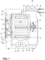
- FIG. 1 is a schematic view of a laundry treating appliance in the form of a clothes washer 10 according to an embodiment of the invention. While the laundry treating appliance is illustrated as a horizontal axis clothes washer 10, the laundry treating appliance according to the invention may be any appliance which performs a cycle of operation on laundry, nonlimiting examples of which include a vertical axis clothes washer, a combination washing machine and dryer, a tumbling or stationary refreshing/revitalizing machine, an extractor, a non-aqueous washing apparatus, and a revitalizing machine.
- the clothes washer 10 described herein shares many features of a traditional automatic clothes washer, which will not be described in detail except as necessary for a complete understanding of the invention. Although much of the remainder of this application will focus on the embodiment of an automatic clothes washer 10, the invention may have utility in other environments, including other cleaning appliances.
- the clothes washer 10 may include a cabinet 12, which may be a housing having a chassis and/or a frame, defining an interior enclosing components typically found in a conventional washing machine, such as motors, pumps, fluid lines, controls, sensors, transducers, and the like. Such components will not be described further herein except as necessary for a complete understanding of the invention.
- a door 14 may be mounted to the cabinet 12 to selectively close an access opening to the interior of a liquid-holding, imperforate tub 16.
- the door 14 may be provided with a fishbowl 15, as hereinafter described in greater detail, and as described in U.S. Patent No. 9,115,461 , entitled "Door Wash Aid Dispenser for a Laundry Treating Appliance".
- the tub 16 may be supported within the cabinet 12 by a suitable suspension system (not shown).
- a drum 18 may be provided within the tub 16 and may have an inner periphery at least partially defining a treating chamber 20 with an open face for receiving fabric, such as laundry to be treated according to a cycle of operation.
- the drum 18 may be mounted for rotation within the tub 16 and may have perforations that permit the flow of liquid between the drum 18 and the tub 16.
- the tub 16 and drum 18 may have aligned openings, which provide access to the treating chamber 20.
- the door 14 may be provided to selectively close at least one of the aligned openings to selectively provide access to the treating chamber 20 through the open face of the treating chamber 20.
- the illustrated clothes washer 10 includes both the tub 16 and the drum 18, with the drum 18 defining the treating chamber 20, it is within the scope of the invention for the clothes washer 10 to include only one receptacle, with the receptacle defining the treating chamber 20 for receiving the laundry load to be treated.
- At least one lifter 22 may be provided in the drum 18 to facilitate movement of the laundry load within the drum 18 as the drum 18 rotates.
- the lifter 22 may be provided on the inner periphery of the drum 18. Multiple lifters 22 may be provided and may optionally be evenly spaced about the inner periphery of the drum 18.
- the drum 18 may be coupled with a motor 24 through a drive shaft 26 for selective rotation of the drum 18 during a cycle of operation. It may also be within the scope of the invention for the motor 24 to be coupled with the drive shaft 26 through a drive belt for selective rotation of the drum 18.
- the motor 24 may rotate the drum 18 at multiple or variable speeds and in one direction or opposite rotational directions.
- a liquid supply system 30 may also be included in the clothes washer 10 to supply liquid to the treating chamber 20. More specifically, liquid, such as water, may be supplied from a liquid source 32, such as a household water supply, to the clothes washer 10 by operation of at least one control valve controlling the flow of water through a supply or inlet conduit 34. As shown herein, separate valves 36, 38 may control the supply of hot and cold water, respectively, through the inlet conduit 34. A flow meter 40 may be positioned in the inlet conduit 34 and may have any suitable output representative of the flow of water through it. The inlet conduit 34 may direct the water from the liquid source 32 to the treating chamber 20, and as an example, the inlet conduit 34 may direct the water into the drum 18. As shown, the inlet conduit 34 may be coupled with a bellows 42.
- the bellows 42 may couple the open face of the tub 16 with a front wall 28 of the cabinet 12, and the door 14 may seal against the bellows 42 when the door 14 closes against the cabinet 12.
- the bellows 42 may be configured with a compliance portion 46, which is illustrated as a fold that may deform to facilitate relative movement of the tub 16 and the front wall 28, and sealing of the closed door 14 against the bellows 42.
- the open face of the treating chamber 20 may coincide with an open face defined by the bellows 42 where the bellows 42 meets the cabinet 12.
- the inlet conduit 34 may comprise a liquid dispenser in the form of a supply nozzle 44, for example, configured to supply the water into the treating chamber 20 along a flow path in a desired pattern and under a predetermined amount of pressure.
- the supply nozzle 44 may be configured to supply a stream of water into the treating chamber 20 by gravity, i.e., a non-pressurized stream.
- the supply nozzle 44 may be mounted to the bellows 42 and be located in any desired position around the open face of the treating chamber 20.
- the supply nozzle 44 may be located at an uppermost position of the treating chamber 20, which would correspond to about the 12 o'clock position on the drum 18, to supply the liquid in a flow path generally downward toward the lowermost position of the treating chamber 20, which would correspond to about the 6 o'clock position on the drum 18.
- Liquid in the treating chamber 20 may flow by gravity to a low portion or sump 50 of the tub 16.
- a liquid drain system 52 may be provided for draining liquid from the treating chamber 20.
- the liquid drain system 52 may include a drain pump 54 and a drain conduit 56.
- the drain pump 54 fluidly couples the sump 50 to the drain conduit 56 such that liquid in the tub 16 may be drained via the drain conduit 56.
- the drain conduit 56 may be coupled with a household drain.
- An optional liquid recirculation system 58 may be provided for recirculating liquid to the treating chamber 20.
- the recirculation system 58 includes a recirculation pump 60 and a spray conduit 62.
- the recirculation pump 60 may fluidly couple the tub 16 to the spray conduit 62 such that liquid in the tub 16 may be supplied to the spray conduit 62, where it may be sprayed into the treating chamber 20.
- the recirculation pump 60 may be fluidly coupled to the sump 50 of the tub 16.
- the spray conduit 62 may direct the liquid from the recirculation pump 60 into the drum 18 in any suitable manner, such as by spraying, dripping, or providing a steady flow of the liquid.
- the clothes washer 10 is illustrated as having separate drain and recirculation pumps 54, 60, in an alternative embodiment, the clothes washer 10 may include a single pump configured to selectively drain or recirculate liquid, such as by configuring the pump to rotate in opposite directions, or by providing a suitable valve system.
- the clothes washer 10 may further include one or more devices for heating the liquid, such as a steam generator and/or a sump heater (not shown).
- the steam generator may be provided to supply steam to the treating chamber 20.
- the sump heater may be used to heat liquid in the sump 50.
- the sump heater may be used to heat laundry (not shown), air, the drum 18, or liquid in the tub 16 to generate steam, in place of or in addition to the steam generator.
- the steam generator may be used to heat the laundry as part of a cycle of operation, much in the same manner as a sump heater, as well as to introduce steam to treat the laundry.
- a controller 64 may be located within the cabinet 12 for controlling the operation of the clothes washer to implement one or more cycles of operation, which may be stored in a memory of the controller 64. Examples, without limitation, of cycles of operation include: wash, heavy duty wash, delicate wash, quick wash, refresh, rinse only, and timed wash.
- a user interface 66 operably coupled to the controller 64 may also be included on the cabinet 12 and may include one or more knobs, switches, displays, and the like for communicating with the user, such as to receive input and provide output. The user may enter many different types of information, including, without limitation, cycle selection and cycle parameters, such as cycle options.
- the controller 64 may be operably coupled with one or more components of the clothes washer 10 for communicating with and controlling the operation of the component to complete a cycle of operation.
- the controller 64 may be operably coupled with at least the motor 24, the valves 36, 38, the flow meter 40, the drain pump 54, and the recirculation pump 60 to control the operation of these and other components to implement one or more of the cycles of operation.
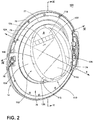
- the door 14 includes a frame 70 surrounding a window 72 that closes an opening 77.
- the frame 70 is illustrated in the present embodiment as generally circular to accommodate a corresponding structure (not shown) on the cabinet 12, but it may be understood that the frame 70 may be any suitable shape, such as elliptical, octagonal, or generally rectangular to cover most or all of the front of the cabinet 12.
- the frame 70 may be configured on one side with a hinge mount 74 that may receive a hinge assembly for movably mounting the door 14 to the cabinet 12, and may support a latch 76 on the opposite side for securing the door 14 to the cabinet 12 in the closed position.
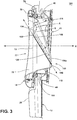
- the frame 70 may be a single element, or may be a composite including an outer trim element 78 and an inner trim element 79 joined together to form the frame 70.
- the trim elements 78, 79 may be permanently joined, such as by welding, adhesives, and the like, or joined to enable disassembly of the frame 70 by suitable removable fasteners, such as threaded fasteners, interference fit and press fit fasteners, and the like.
- the inner trim element 79 of the frame 70 defines the opening 77.
- the frame 70 may be provided with one or more handles (not shown), including recesses formed in the outer trim element 78 or exterior portion of the frame 70, for grasping by a user to open and close the door 14.
- the window 72 may be generally flat or planar, and substantially translucent or transparent so that a user may view the interior of the treating chamber 20 when the door 14 is closed.
- the window 72 may be omitted or opaque.
- the window 72 may be circular in shape, as illustrated for exemplary purposes, corresponding with the circular shape of the frame 70. Nevertheless, it is within the scope of the invention for the window 72 to have any suitable areal shape consistent with the shape of the door 14.
- the fishbowl 110 is disposed on the window 72, and the fishbowl 110 can be substantially translucent or transparent to enable viewing through the window 72 and the fishbowl 110.
- the fishbowl 110 is made up of a plastic, and can be formed by injection molding. By providing a fishbowl 110 that is made of translucent or transparent plastic, the fishbowl 110 provides the aesthetic appeal of a glass fishbowl, but enables capacity-enhancing benefits described herein due to the versatility of plastic as compared to glass.
- the fishbowl 110 may be mounted to the window 72, the frame 70, to both the frame 70 and the window 72, or may be integrally formed with the frame 70 or with the window 72.
- the fishbowl 110 may be sized for receipt within the open face of the bellows 42, as will be discussed in more detail below.
- the fishbowl 110 includes a generally annular or "ring-like" peripheral wall 112 and is associated with a rear side of the door 14, i.e., the side of the door 14 that faces the treating chamber 20 when the door 14 is closed.
- the peripheral wall 112 forms an annulus 116, which may form a complete annulus, or a partial annulus defining, or bounding an interior 128.
- a central axis "X" is defined by the peripheral wall 112 wherein the central axis "X" projects through the center of the peripheral wall 112, and in exemplary implementations is parallel to the surface on which the clothes washer 10 rests.
- the peripheral wall 112 comprises a dual-wall structure with a first wall 134 and a second wall 136.
- the junction at which the first wall 134 and second wall 136 intersect forms an apex 140 of the peripheral wall 112, which is curved or rounded.
- the depth from the frame 70 to the apex 140 of the peripheral wall varies.
- An upper portion 124 of the peripheral wall 112 tends have less depth than the lower portion 126 of the peripheral wall 112. Reduction of the area of the second wall 136 causes more efficiency in keeping laundry, such as socks, from resting on the second wall 136 and creating a build-up of laundry.
- An inner wall 114 is disposed within the peripheral wall 112 and comprises a downwardly sloping section 114a and a surface "S".
- the downwardly sloping section 114a may function to direct liquid and laundry items moving along the interior 128 of the fishbowl 110 toward the treating chamber 20.
- the surface "S" of the inner wall 114 intersects the peripheral wall 112 at intersection 122.
- the intersection 122 defines a radius having a radius of curvature 150, illustrated in FIG.4 .
- Virtual extensions of the inner wall 114 and the second wall 136 of the peripheral wall 112 are shown in dashed lines.
- a fillet 154 is disposed within the intersection 122 and can define at least a portion of a circle 156 or an arcuate surface, such that an effective radius of curvature 150 is defined between the fillet 154 and a center point 152 of the circle 156.
- the radius of curvature 150 can be less than 200 mm and as low as 138 mm. Decreasing the radius of curvature 150 increases the capacity of the treating chamber 20 by utilizing less material and thereby creating more space in the treating chamber 20.
- the reduced radius of curvature 150 for a fishbowl 110 can be correlated to the ability to manufacture plastic for a fishbowl 110 at a thickness of 4 mm, while glass is only able to be manufactured to a thickness greater than 6 mm.
- the frame 70 may have an outer trim element 78 and an inner trim element 79.
- the fishbowl 110 may have a generally circular perimeter flange 181, defining a planar rear face 168 that may enable the window 72 and the fishbowl 110 perimeter flange 181 to be "sandwiched" between the outer trim element 78 and the inner trim element 79 when joined together.
- the fishbowl 110 may be mounted between the outer trim element 78 and inner trim element 79 so that the planar rear face 168 is adjacent to and abuts the window 72.
- the window 72 and the fishbowl 110 may be readily replaced, as necessary, merely by separating the trim elements 78, 79.
- the inner trim element 79 and fishbowl 110 may be fabricated as a single element for coupling with the outer trim element 78. With this configuration, the window 72 may be "sandwiched" therebetween.
- the fishbowl 110 When the door 14 is closed, the fishbowl 110 extends into the treating chamber 20 such that different parts of the fishbowl 110, such as the peripheral wall 112, may project different distances into the treating chamber 20, i.e. away from the window 72. In this configuration, the fishbowl 110 may overlie the compliance portion 46 of the bellows 42 and the rim of the drum 18. In order to enable movement and sealing, the compliance portion 46 may tend to deform in such a manner as to allow laundry items to enter around and behind the compliance portion 46. The extension of the fishbowl 110 over the compliance portion 46 and into the treating chamber 20 may prevent laundry items from becoming entrapped by the bellows 42 between the drum 18 and the door 14 or cabinet 12.
- Laundry items may travel downward along the inner wall 114 to the peripheral wall 112 and the downwardly sloping section 114a, and then slide over and past the bellows 42 into the treating chamber 20.
- the first wall 134 and second wall 136 of the peripheral wall 112 form a V-shaped cross-section at the apex 140.
- the fishbowl 110 may also seal against the bellows 42 by the peripheral wall 112 abutting the bellows 42 around the circumference of the fishbowl 110.
- the seal between the fishbowl 110 and the bellows 42 may inhibit the laundry from migrating through the open face of the treating chamber 20, thereby retaining the laundry load in the treating chamber 20. It may also form a fluid seal to prevent leakage of treating fluid out of the clothes washer 10 between the door 14 and the cabinet 12.
- An included angle ⁇ is defined by the intersection of surface S of the downwardly sloping section 114a of the inner wall 114 relative to the central axis X. Extensions are shown in dashed lines along the surface S of the downwardly sloping section 114a of the inner wall 114 to better view the included angle ⁇ relative to the central axis X.
- the included angle ⁇ is generally greater than 30°.
- Using plastic to manufacture the fishbowl 110 enables the included angle ⁇ to be as low as, or even lower than 30°.
- a glass fishbowl is typically only able to be manufactured to have a minimum included angle of 45°.
- the included angle ⁇ is about 56°.
- the included angle ⁇ is less than about 60°, less than about 50°, less than about 40°, or less than about 35°. Decreasing the included angle ⁇ , increases the capacity of the treating chamber 20, therefore. Capacity of the treating chamber 20 is influenced because the included angle ⁇ affects the slope of the downwardly sloping section 114a. Decreasing the included angle ⁇ causes the location of the intersection 122 to move vertically downwards so that the inner wall 114 has more horizontal surface area. In other words, intersection 122 moves vertically downwards when the included angle ⁇ is decreased, resulting in more capacity because more horizontal surface area of the inner wall 114 is exposed, creating more space in the drum.
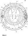
- Laundry items may move along a path defined by the fishbowl 110 and the varying depth of the annulus 116.
- laundry items in the treating chamber 20 may travel upward generally circumferentially along the outer wall of the drum 18 on the lifters 22 until, at some point of rotation, the laundry items may move from the lifters 22 to the bottom of the drum 18 in a repeated tumbling action.
- a portion of the laundry load, and to some extent the treating liquid may move upwardly along the annulus 116, i.e. the peripheral wall 112, to the upper portion 124 of peripheral wall 112 having the shallowest depth.
- a portion may cross over the upper portion 124 to the inner wall 114 to fall along the downwardly sloping section 114a and the lower portion 126 of the peripheral wall 112.
- the downwardly sloping section 114a as a result of its downward slope, may direct the laundry items into the treating chamber 20.
- laundry items may be inhibited from contact with the bellows 42, and possible entry into a channel or space between the cabinet 12 and the bellows 42.
- a vent is positioned on the upper portion of the fishbowl 110. If the inner wall 114 spans only part of the interior, an opening or vent can be formed in the fishbowl between the inner wall and the annulus.
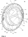
- FIGS. 6 , 7 , 8 , and 9 similar alternative embodiments of a fishbowl for a door according to the present disclosure are illustrated with like parts identified by like numerals increasing by 100, with it being understood that the description of the like parts of the first embodiment applies to the additional embodiment, unless otherwise noted.
- FIG. 6 illustrates a rear perspective view of a door 200 according to another embodiment wherein the intersection 222 of the inner wall 214 and the peripheral wall 212 of fishbowl 210 is spaced further from the upper portion 224 of the annulus 216 and closer to the lower portion 226 than intersection 122 on fishbowl 110.
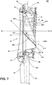
- the included angle ⁇ defined by the intersection 222 of the inner wall 214 and the peripheral wall 212 relative to the central axis X is about 43°.
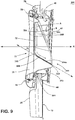
- FIG. 8 illustrates a rear perspective view of a door 300 according to another embodiment wherein the intersection 322 of the inner wall 314 and the peripheral wall 312 of fishbowl 310 is spaced further from the upper portion 324 of the annulus 316 and closer to the lower portion 126 than intersection 222 on fishbowl 210.
- the included angle ⁇ defined by the intersection 322 of the inner wall 314 and the peripheral wall 312 relative to the central axis X is about 30°. Since Fishbowl 310 has the sharpest included angle ⁇ , it has the highest capacity of the example embodiments.
Landscapes
- Engineering & Computer Science (AREA)
- Textile Engineering (AREA)
- Main Body Construction Of Washing Machines And Laundry Dryers (AREA)
Description
- Laundry treating appliances, such as front-loading, horizontal axis clothes washers, typically have doors for accessing the treating chamber at least partially formed by a rotating drum. Such doors may include a cast glass window to enable observation of a laundry load as the appliance is operated. In order to maintain the moving laundry load away from the door and within the treating chamber, the window may be cast from glass with a convex or "bubble" shape, called a fishbowl, extending away from the inner face of the door and somewhat into the treating chamber when the door is closed.
- The thick, cast glass of a fishbowl is typically expensive to manufacture, heavy, and occupies a substantial portion of the treating chamber that could otherwise be used for treating laundry. Glass used for a fishbowl is manufactured at a thickness of greater than 6 mm to prevent damage such as cracking. A fishbowl can comprise a radius of curvature that is defined by an intersection of an inner wall and a peripheral wall. Furthermore, the sharper the radius of curvature of a fishbowl, the greater capacity of the treating chamber. Due to the manufacturing constraints of casting glass, the minimum radius of curvature is usually only 210mm.
- Document
US 2013/160501 A1 discloses a laundry treating appliance including a door movably mounted to the front wall, having a planar window element and a projection extending from the planar window element, the projection having at least a portion overlying the compliance portion to retard an item of laundry from entering the compliance portion during rotation of the drum. - Document
WO 2011/154445 A2 discloses a washing machine having a transparent lid whose portion contains a progressive-inclined form when the lid is closed. -
Document DE 10 2009 044711 B3 discloses a washing machine, having a filling material comprising regions that are formed-out symmetrically within a lower rising region of a truncated cone surface, and causing movement component for laundry during washing operation in an axial direction of the drum. - The present innovation relates to a door assembly for a laundry treating appliance comprising: a frame defining an opening; a window closing the opening; and a transparent or translucent plastic fishbowl adjacent the window, the fishbowl being convex shaped and extending away from the inner face of the door into the treating chamber when the door is closed, and comprising: a peripheral wall defining at least a partial annulus with a central axis; wherein said fishbowl further comprises an inner wall located within the peripheral wall to close the at least a partial annulus and defining a surface that intersects with the peripheral wall defining an intersection, wherein a fillet is disposed within the intersection and defines at least a portion of a circle or an arcuate surface, such that an effective radius of curvature is defined between the fillet and a center point of the circle, the radius of curvature being less than 200 mm and as low as 138 mm.
- In the drawings:
-
FIG. 1 is a schematic view of a laundry treating appliance in the form of a clothes washer according to an aspect of the innovation. -
FIG. 2 is a rear perspective view of the door illustrated inFIG. 1 . -
FIG. 3 is a cross-sectional view taken along view line III-III ofFIG. 2 . -
FIG. 4 is a cross-sectional view taken along view line IV-IV ofFIG. 2 -
FIG. 5 is a rear elevation view of the door inFIG. 1 illustrating fluid flow paths along the door and adjoining fishbowl. -
FIG. 6 is a rear perspective view of a door according to another embodiment. -
FIG. 7 is a cross-sectional view taken along view line V-V ofFIG. 6 . -
FIG. 8 is a rear perspective view of a door according to another embodiment. -
FIG. 9 is a cross-sectional view taken along view line VI-VI ofFIG. 8 . -
FIG. 1 is a schematic view of a laundry treating appliance in the form of aclothes washer 10 according to an embodiment of the invention. While the laundry treating appliance is illustrated as a horizontalaxis clothes washer 10, the laundry treating appliance according to the invention may be any appliance which performs a cycle of operation on laundry, nonlimiting examples of which include a vertical axis clothes washer, a combination washing machine and dryer, a tumbling or stationary refreshing/revitalizing machine, an extractor, a non-aqueous washing apparatus, and a revitalizing machine. Theclothes washer 10 described herein shares many features of a traditional automatic clothes washer, which will not be described in detail except as necessary for a complete understanding of the invention. Although much of the remainder of this application will focus on the embodiment of anautomatic clothes washer 10, the invention may have utility in other environments, including other cleaning appliances. - The
clothes washer 10 may include acabinet 12, which may be a housing having a chassis and/or a frame, defining an interior enclosing components typically found in a conventional washing machine, such as motors, pumps, fluid lines, controls, sensors, transducers, and the like. Such components will not be described further herein except as necessary for a complete understanding of the invention. - A
door 14 may be mounted to thecabinet 12 to selectively close an access opening to the interior of a liquid-holding,imperforate tub 16. Thedoor 14 may be provided with afishbowl 15, as hereinafter described in greater detail, and as described inU.S. Patent No. 9,115,461 tub 16 may be supported within thecabinet 12 by a suitable suspension system (not shown). Adrum 18 may be provided within thetub 16 and may have an inner periphery at least partially defining a treatingchamber 20 with an open face for receiving fabric, such as laundry to be treated according to a cycle of operation. Thedrum 18 may be mounted for rotation within thetub 16 and may have perforations that permit the flow of liquid between thedrum 18 and thetub 16. - The
tub 16 anddrum 18 may have aligned openings, which provide access to the treatingchamber 20. Thedoor 14 may be provided to selectively close at least one of the aligned openings to selectively provide access to the treatingchamber 20 through the open face of the treatingchamber 20. While the illustratedclothes washer 10 includes both thetub 16 and thedrum 18, with thedrum 18 defining the treatingchamber 20, it is within the scope of the invention for theclothes washer 10 to include only one receptacle, with the receptacle defining the treatingchamber 20 for receiving the laundry load to be treated. - At least one
lifter 22 may be provided in thedrum 18 to facilitate movement of the laundry load within thedrum 18 as thedrum 18 rotates. Thelifter 22 may be provided on the inner periphery of thedrum 18.Multiple lifters 22 may be provided and may optionally be evenly spaced about the inner periphery of thedrum 18. - The
drum 18 may be coupled with amotor 24 through adrive shaft 26 for selective rotation of thedrum 18 during a cycle of operation. It may also be within the scope of the invention for themotor 24 to be coupled with thedrive shaft 26 through a drive belt for selective rotation of thedrum 18. Themotor 24 may rotate thedrum 18 at multiple or variable speeds and in one direction or opposite rotational directions. - A
liquid supply system 30 may also be included in theclothes washer 10 to supply liquid to the treatingchamber 20. More specifically, liquid, such as water, may be supplied from aliquid source 32, such as a household water supply, to the clothes washer 10 by operation of at least one control valve controlling the flow of water through a supply orinlet conduit 34. As shown herein,separate valves inlet conduit 34. Aflow meter 40 may be positioned in theinlet conduit 34 and may have any suitable output representative of the flow of water through it. Theinlet conduit 34 may direct the water from theliquid source 32 to the treatingchamber 20, and as an example, theinlet conduit 34 may direct the water into thedrum 18. As shown, theinlet conduit 34 may be coupled with abellows 42. - The
bellows 42 may couple the open face of thetub 16 with afront wall 28 of thecabinet 12, and thedoor 14 may seal against thebellows 42 when thedoor 14 closes against thecabinet 12. Thebellows 42 may be configured with acompliance portion 46, which is illustrated as a fold that may deform to facilitate relative movement of thetub 16 and thefront wall 28, and sealing of the closeddoor 14 against thebellows 42. The open face of the treatingchamber 20 may coincide with an open face defined by thebellows 42 where thebellows 42 meets thecabinet 12. - The
inlet conduit 34 may comprise a liquid dispenser in the form of asupply nozzle 44, for example, configured to supply the water into the treatingchamber 20 along a flow path in a desired pattern and under a predetermined amount of pressure. For example, thesupply nozzle 44 may be configured to supply a stream of water into the treatingchamber 20 by gravity, i.e., a non-pressurized stream. Thesupply nozzle 44 may be mounted to thebellows 42 and be located in any desired position around the open face of the treatingchamber 20. As an example, thesupply nozzle 44 may be located at an uppermost position of the treatingchamber 20, which would correspond to about the 12 o'clock position on thedrum 18, to supply the liquid in a flow path generally downward toward the lowermost position of the treatingchamber 20, which would correspond to about the 6 o'clock position on thedrum 18. - Liquid in the treating
chamber 20 may flow by gravity to a low portion orsump 50 of thetub 16. Aliquid drain system 52 may be provided for draining liquid from the treatingchamber 20. Theliquid drain system 52 may include adrain pump 54 and adrain conduit 56. Thedrain pump 54 fluidly couples thesump 50 to thedrain conduit 56 such that liquid in thetub 16 may be drained via thedrain conduit 56. Thedrain conduit 56 may be coupled with a household drain. - An optional
liquid recirculation system 58 may be provided for recirculating liquid to the treatingchamber 20. As illustrated, therecirculation system 58 includes arecirculation pump 60 and aspray conduit 62. Therecirculation pump 60 may fluidly couple thetub 16 to thespray conduit 62 such that liquid in thetub 16 may be supplied to thespray conduit 62, where it may be sprayed into the treatingchamber 20. Therecirculation pump 60 may be fluidly coupled to thesump 50 of thetub 16. Thespray conduit 62 may direct the liquid from therecirculation pump 60 into thedrum 18 in any suitable manner, such as by spraying, dripping, or providing a steady flow of the liquid. While theclothes washer 10 is illustrated as having separate drain and recirculation pumps 54, 60, in an alternative embodiment, theclothes washer 10 may include a single pump configured to selectively drain or recirculate liquid, such as by configuring the pump to rotate in opposite directions, or by providing a suitable valve system. - The
clothes washer 10 may further include one or more devices for heating the liquid, such as a steam generator and/or a sump heater (not shown). The steam generator may be provided to supply steam to the treatingchamber 20. The sump heater may be used to heat liquid in thesump 50. Alternatively, the sump heater may be used to heat laundry (not shown), air, thedrum 18, or liquid in thetub 16 to generate steam, in place of or in addition to the steam generator. The steam generator may be used to heat the laundry as part of a cycle of operation, much in the same manner as a sump heater, as well as to introduce steam to treat the laundry. - A
controller 64 may be located within thecabinet 12 for controlling the operation of the clothes washer to implement one or more cycles of operation, which may be stored in a memory of thecontroller 64. Examples, without limitation, of cycles of operation include: wash, heavy duty wash, delicate wash, quick wash, refresh, rinse only, and timed wash. Auser interface 66 operably coupled to thecontroller 64 may also be included on thecabinet 12 and may include one or more knobs, switches, displays, and the like for communicating with the user, such as to receive input and provide output. The user may enter many different types of information, including, without limitation, cycle selection and cycle parameters, such as cycle options. During operation of theclothes washer 10, thecontroller 64 may be operably coupled with one or more components of theclothes washer 10 for communicating with and controlling the operation of the component to complete a cycle of operation. For example, thecontroller 64 may be operably coupled with at least themotor 24, thevalves flow meter 40, thedrain pump 54, and therecirculation pump 60 to control the operation of these and other components to implement one or more of the cycles of operation. - Referring now to the rear perspective view of the
door assembly 100 comprising adoor 14 and adjoiningfishbowl 110 inFIG. 2 , thedoor 14 includes aframe 70 surrounding awindow 72 that closes anopening 77. Theframe 70 is illustrated in the present embodiment as generally circular to accommodate a corresponding structure (not shown) on thecabinet 12, but it may be understood that theframe 70 may be any suitable shape, such as elliptical, octagonal, or generally rectangular to cover most or all of the front of thecabinet 12. Theframe 70 may be configured on one side with ahinge mount 74 that may receive a hinge assembly for movably mounting thedoor 14 to thecabinet 12, and may support alatch 76 on the opposite side for securing thedoor 14 to thecabinet 12 in the closed position. - Referring to
FIG. 3 , theframe 70 may be a single element, or may be a composite including anouter trim element 78 and aninner trim element 79 joined together to form theframe 70. Thetrim elements frame 70 by suitable removable fasteners, such as threaded fasteners, interference fit and press fit fasteners, and the like. Theinner trim element 79 of theframe 70 defines theopening 77. Theframe 70 may be provided with one or more handles (not shown), including recesses formed in theouter trim element 78 or exterior portion of theframe 70, for grasping by a user to open and close thedoor 14. - The
window 72 may be generally flat or planar, and substantially translucent or transparent so that a user may view the interior of the treatingchamber 20 when thedoor 14 is closed. In an alternative embodiment, thewindow 72 may be omitted or opaque. Further, thewindow 72 may be circular in shape, as illustrated for exemplary purposes, corresponding with the circular shape of theframe 70. Nevertheless, it is within the scope of the invention for thewindow 72 to have any suitable areal shape consistent with the shape of thedoor 14. - The
fishbowl 110 is disposed on thewindow 72, and thefishbowl 110 can be substantially translucent or transparent to enable viewing through thewindow 72 and thefishbowl 110. Thefishbowl 110 is made up of a plastic, and can be formed by injection molding. By providing afishbowl 110 that is made of translucent or transparent plastic, thefishbowl 110 provides the aesthetic appeal of a glass fishbowl, but enables capacity-enhancing benefits described herein due to the versatility of plastic as compared to glass. Thefishbowl 110 may be mounted to thewindow 72, theframe 70, to both theframe 70 and thewindow 72, or may be integrally formed with theframe 70 or with thewindow 72. Thefishbowl 110 may be sized for receipt within the open face of thebellows 42, as will be discussed in more detail below. - Turning back to
FIG. 2 , thefishbowl 110 includes a generally annular or "ring-like"peripheral wall 112 and is associated with a rear side of thedoor 14, i.e., the side of thedoor 14 that faces the treatingchamber 20 when thedoor 14 is closed. Theperipheral wall 112 forms anannulus 116, which may form a complete annulus, or a partial annulus defining, or bounding an interior 128. A central axis "X" is defined by theperipheral wall 112 wherein the central axis "X" projects through the center of theperipheral wall 112, and in exemplary implementations is parallel to the surface on which theclothes washer 10 rests. - The
peripheral wall 112 comprises a dual-wall structure with afirst wall 134 and asecond wall 136. The junction at which thefirst wall 134 andsecond wall 136 intersect forms an apex 140 of theperipheral wall 112, which is curved or rounded. The depth from theframe 70 to the apex 140 of the peripheral wall varies. Anupper portion 124 of theperipheral wall 112 tends have less depth than thelower portion 126 of theperipheral wall 112. Reduction of the area of thesecond wall 136 causes more efficiency in keeping laundry, such as socks, from resting on thesecond wall 136 and creating a build-up of laundry. - An
inner wall 114 is disposed within theperipheral wall 112 and comprises a downwardly slopingsection 114a and a surface "S". The downwardly slopingsection 114a may function to direct liquid and laundry items moving along theinterior 128 of thefishbowl 110 toward the treatingchamber 20. The surface "S" of theinner wall 114 intersects theperipheral wall 112 atintersection 122. - The
intersection 122 defines a radius having a radius ofcurvature 150, illustrated inFIG.4 . Virtual extensions of theinner wall 114 and thesecond wall 136 of theperipheral wall 112 are shown in dashed lines. Afillet 154 is disposed within theintersection 122 and can define at least a portion of acircle 156 or an arcuate surface, such that an effective radius ofcurvature 150 is defined between thefillet 154 and acenter point 152 of thecircle 156. The radius ofcurvature 150 can be less than 200 mm and as low as 138 mm. Decreasing the radius ofcurvature 150 increases the capacity of the treatingchamber 20 by utilizing less material and thereby creating more space in the treatingchamber 20. Without wishing to be bound by theory, the reduced radius ofcurvature 150 for afishbowl 110 can be correlated to the ability to manufacture plastic for afishbowl 110 at a thickness of 4 mm, while glass is only able to be manufactured to a thickness greater than 6 mm. - As best seen in
FIG. 3 , the cross-sectional view taken along view line III-III ofFIG. 2 , theframe 70 may have anouter trim element 78 and aninner trim element 79. Thefishbowl 110 may have a generallycircular perimeter flange 181, defining a planarrear face 168 that may enable thewindow 72 and thefishbowl 110perimeter flange 181 to be "sandwiched" between theouter trim element 78 and theinner trim element 79 when joined together. Thefishbowl 110 may be mounted between theouter trim element 78 andinner trim element 79 so that the planarrear face 168 is adjacent to and abuts thewindow 72. This may enable thewindow 72 and thefishbowl 110 to be readily replaced, as necessary, merely by separating thetrim elements inner trim element 79 andfishbowl 110 may be fabricated as a single element for coupling with theouter trim element 78. With this configuration, thewindow 72 may be "sandwiched" therebetween. - When the
door 14 is closed, thefishbowl 110 extends into the treatingchamber 20 such that different parts of thefishbowl 110, such as theperipheral wall 112, may project different distances into the treatingchamber 20, i.e. away from thewindow 72. In this configuration, thefishbowl 110 may overlie thecompliance portion 46 of thebellows 42 and the rim of thedrum 18. In order to enable movement and sealing, thecompliance portion 46 may tend to deform in such a manner as to allow laundry items to enter around and behind thecompliance portion 46. The extension of thefishbowl 110 over thecompliance portion 46 and into the treatingchamber 20 may prevent laundry items from becoming entrapped by thebellows 42 between thedrum 18 and thedoor 14 orcabinet 12. Laundry items may travel downward along theinner wall 114 to theperipheral wall 112 and the downwardly slopingsection 114a, and then slide over and past thebellows 42 into the treatingchamber 20. Thefirst wall 134 andsecond wall 136 of theperipheral wall 112 form a V-shaped cross-section at the apex 140. - The
fishbowl 110 may also seal against thebellows 42 by theperipheral wall 112 abutting thebellows 42 around the circumference of thefishbowl 110. The seal between thefishbowl 110 and thebellows 42 may inhibit the laundry from migrating through the open face of the treatingchamber 20, thereby retaining the laundry load in the treatingchamber 20. It may also form a fluid seal to prevent leakage of treating fluid out of theclothes washer 10 between thedoor 14 and thecabinet 12. - An included angle θ is defined by the intersection of surface S of the downwardly sloping
section 114a of theinner wall 114 relative to the central axis X. Extensions are shown in dashed lines along the surface S of the downwardly slopingsection 114a of theinner wall 114 to better view the included angle θ relative to the central axis X. The included angle θ is generally greater than 30°. Using plastic to manufacture thefishbowl 110 enables the included angle θ to be as low as, or even lower than 30°. A glass fishbowl is typically only able to be manufactured to have a minimum included angle of 45°. Here, the included angle θ is about 56°. In exemplary implementations, the included angle θ is less than about 60°, less than about 50°, less than about 40°, or less than about 35°. Decreasing the included angle θ, increases the capacity of the treatingchamber 20, therefore. Capacity of the treatingchamber 20 is influenced because the included angle θ affects the slope of the downwardly slopingsection 114a. Decreasing the included angle θ causes the location of theintersection 122 to move vertically downwards so that theinner wall 114 has more horizontal surface area. In other words,intersection 122 moves vertically downwards when the included angle θ is decreased, resulting in more capacity because more horizontal surface area of theinner wall 114 is exposed, creating more space in the drum. - Laundry items may move along a path defined by the
fishbowl 110 and the varying depth of theannulus 116. As thedrum 18 rotates during a cycle of operation, laundry items in the treatingchamber 20 may travel upward generally circumferentially along the outer wall of thedrum 18 on thelifters 22 until, at some point of rotation, the laundry items may move from thelifters 22 to the bottom of thedrum 18 in a repeated tumbling action. As illustrated by the arrows labeled "A" inFIG. 5 , a portion of the laundry load, and to some extent the treating liquid, may move upwardly along theannulus 116, i.e. theperipheral wall 112, to theupper portion 124 ofperipheral wall 112 having the shallowest depth. As the laundry items slide away from thelifters 22, a portion may cross over theupper portion 124 to theinner wall 114 to fall along the downwardly slopingsection 114a and thelower portion 126 of theperipheral wall 112. The downwardly slopingsection 114a, as a result of its downward slope, may direct the laundry items into the treatingchamber 20. As this occurs, laundry items may be inhibited from contact with thebellows 42, and possible entry into a channel or space between thecabinet 12 and thebellows 42. It is contemplated that a vent is positioned on the upper portion of thefishbowl 110. If theinner wall 114 spans only part of the interior, an opening or vent can be formed in the fishbowl between the inner wall and the annulus. - Turning to
FIGS. 6 ,7 ,8 , and9 , similar alternative embodiments of a fishbowl for a door according to the present disclosure are illustrated with like parts identified by like numerals increasing by 100, with it being understood that the description of the like parts of the first embodiment applies to the additional embodiment, unless otherwise noted. -
FIG. 6 illustrates a rear perspective view of adoor 200 according to another embodiment wherein theintersection 222 of theinner wall 214 and theperipheral wall 212 offishbowl 210 is spaced further from theupper portion 224 of theannulus 216 and closer to thelower portion 226 thanintersection 122 onfishbowl 110. - As can be seen more clearly in
FIG. 7 , the included angle θ defined by theintersection 222 of theinner wall 214 and theperipheral wall 212 relative to the central axis X is about 43°. -
FIG. 8 illustrates a rear perspective view of adoor 300 according to another embodiment wherein theintersection 322 of theinner wall 314 and theperipheral wall 312 offishbowl 310 is spaced further from theupper portion 324 of theannulus 316 and closer to thelower portion 126 thanintersection 222 onfishbowl 210. - As can be seen more clearly in
FIG. 9 , the included angle θ defined by theintersection 322 of theinner wall 314 and theperipheral wall 312 relative to the central axis X is about 30°. SinceFishbowl 310 has the sharpest included angle θ, it has the highest capacity of the example embodiments. - To the extent not already described, the different features and structures of the various embodiments can be used in combination with each other as desired. That one feature may not be illustrated in all of the embodiments is not meant to be construed that it cannot be, but is done for brevity of description. Thus, the various features of the different embodiments can be mixed and matched as desired to form new embodiments, whether or not the new embodiments are expressly described. Further, while the invention has been specifically described in connection with certain specific embodiments thereof, it is to be understood that this is by way of illustration and not of limitation.
- While the invention has been specifically described in connection with certain specific embodiments thereof, it is to be understood that this is by way of illustration and not of limitation, and the scope of the appended claims should be construed as broadly as the prior art will permit. It should also be noted that all elements of all of the claims may be combined with each other in any possible combination, even if the combinations have not been expressly claimed.
Claims (6)
- A door assembly (100, 200, 300) for a laundry treating appliance (10) comprising:a frame (70) defining an opening (77);a window (72) closing the opening (77); anda transparent or translucent plastic fishbowl (110, 210, 310) adjacent the window (72), the fishbowl (110, 210, 310) being convex shaped and extending away from the inner face of the door into the treating chamber when the door is closed, and comprising:
a peripheral wall (112, 212, 312) defining at least a partial annulus (116, 216, 316) with a central axis;
characterized in thatsaid fishbowl (110, 210, 310) further comprises
an inner wall (114, 214, 314) located within the peripheral wall (112, 212, 312) to close the at least partial annulus (116, 216, 316) and defining a surface that intersects with the peripheral wall (112, 212, 312) defining an intersection (122), wherein a fillet (154) is disposed within the intersection (122) and defines at least a portion of a circle (156) or an arcuate surface, such that an effective radius of curvature (150) is defined between the fillet (154) and a center point (152) of the circle (156), the radius of curvature (150) being less than 200 mm and as low as 138 mm. - The door assembly (100, 200, 300) of claim 1 wherein the peripheral wall (112, 212, 312) defines a complete annulus bounding an interior (128, 228, 328).
- The door assembly (100, 200, 300) of any of the preceding claims wherein the peripheral wall (112, 212, 312) has a dual-wall structure comprising first and second walls (134, 136, 234, 236, 334, 336).
- The door assembly (100, 200, 300) of claim 3 wherein the first and second walls (134, 136, 234, 236, 334, 336) intersect to define a junction forming an apex (140, 240, 340) of the peripheral wall (112, 212, 312).
- The door assembly (100, 200, 300) of claim 4 wherein the first and second walls (134, 136, 234, 236, 334, 336) form a V-shaped cross section.
- The door assembly (100, 200, 300) of any of the preceding claims wherein the inner wall is planar (114, 214, 314).
Applications Claiming Priority (1)
| Application Number | Priority Date | Filing Date | Title |
|---|---|---|---|
| US15/255,213 US10132021B2 (en) | 2016-09-02 | 2016-09-02 | Laundry treating appliance door assembly comprising a plastic fishbowl |
Publications (2)
| Publication Number | Publication Date |
|---|---|
| EP3290575A1 EP3290575A1 (en) | 2018-03-07 |
| EP3290575B1 true EP3290575B1 (en) | 2020-06-10 |
Family
ID=59416568
Family Applications (1)
| Application Number | Title | Priority Date | Filing Date |
|---|---|---|---|
| EP17183417.9A Active EP3290575B1 (en) | 2016-09-02 | 2017-07-26 | Door assembly of a laundry treating appliance |
Country Status (2)
| Country | Link |
|---|---|
| US (6) | US10132021B2 (en) |
| EP (1) | EP3290575B1 (en) |
Families Citing this family (11)
| Publication number | Priority date | Publication date | Assignee | Title |
|---|---|---|---|---|
| US10132021B2 (en) | 2016-09-02 | 2018-11-20 | Whirlpool Corporation | Laundry treating appliance door assembly comprising a plastic fishbowl |
| PL3323929T3 (en) | 2016-11-21 | 2021-06-28 | Electrolux Appliances Aktiebolag | A door assembly for a laundry treatment machine |
| USD856615S1 (en) * | 2017-10-19 | 2019-08-13 | Whirlpool Corporation | Door bowl for a laundry treating appliance door |
| WO2019107857A1 (en) * | 2017-11-28 | 2019-06-06 | 엘지전자 주식회사 | Clothing treatment device |
| US11208750B2 (en) | 2018-12-29 | 2021-12-28 | Whirlpool Corporation | Laundry appliance with a deflector |
| CN115485429A (en) * | 2020-04-15 | 2022-12-16 | 伟视达电子工贸有限公司 | Washing machine door and washing machine |
| CN116472377A (en) * | 2020-11-09 | 2023-07-21 | 伊士曼化工公司 | washing machine door assembly |
| US12595612B2 (en) | 2021-12-13 | 2026-04-07 | Whirlpool Corporation | Appliance sanitization system that utilizes ozone gas |
| US12331451B2 (en) | 2022-02-21 | 2025-06-17 | Haier Us Appliance Solutions, Inc. | Dryer appliance and compartment for non-tumbling items |
| US12410550B2 (en) | 2022-11-28 | 2025-09-09 | Haier Us Appliance Solutions, Inc. | Laundry appliance door for treatment of non-moving articles |
| WO2025241843A1 (en) * | 2024-05-20 | 2025-11-27 | 南京石头创新科技有限公司 | Door glass, door body assembly, and clothes treatment device |
Family Cites Families (41)
| Publication number | Priority date | Publication date | Assignee | Title |
|---|---|---|---|---|
| US3520568A (en) * | 1969-04-02 | 1970-07-14 | Gen Electric | Door latch for appliance cabinets and the like |
| US4987627A (en) | 1990-01-05 | 1991-01-29 | Whirlpool Corporation | High performance washing process for vertical axis automatic washer |
| DE10031170A1 (en) * | 2000-06-27 | 2002-01-10 | Bsh Bosch Siemens Hausgeraete | gasket |
| US6616030B2 (en) | 2001-05-07 | 2003-09-09 | West Bond, Inc. | Gantry mounted ultrasonic wire bonder with orbital bonding tool head |
| KR20040011827A (en) | 2002-07-30 | 2004-02-11 | 엘지전자 주식회사 | Door for drum type-washing machine |
| WO2006080788A1 (en) * | 2005-01-25 | 2006-08-03 | Lg Electronics Inc. | A door for a washing or drying machine |
| CA2508860C (en) * | 2005-05-30 | 2007-10-16 | Camco Inc. | Clothes dryer reversible door assembly |
| DE102006036352B4 (en) * | 2006-08-02 | 2009-11-12 | Miele & Cie. Kg | Porthole door for a front-loading laundry machine such as a washing machine, washer-dryer or tumble dryer |
| US8567219B2 (en) * | 2007-11-01 | 2013-10-29 | Lg Electronics Inc. | Washing machine |
| US20110025177A1 (en) * | 2009-07-30 | 2011-02-03 | Bsh Home Appliances Corporation | Overmold seal and ramp for a household appliance door |
| US8631527B2 (en) * | 2009-08-10 | 2014-01-21 | Whirlpool Corporation | Laundry treating appliance with tumble pattern control |
| EP2302128A1 (en) | 2009-09-24 | 2011-03-30 | BSH Bosch und Siemens Hausgeräte GmbH | Door for a laundry dryer, method of manufacturing such door and method of operating such door |
| KR101407961B1 (en) * | 2009-10-13 | 2014-06-18 | 삼성전자 주식회사 | Door lock control device of a washing machine and method thereof |
| DE102009044711B3 (en) | 2009-12-01 | 2011-04-07 | Miele & Cie. Kg | Washing machine, has filling material comprising regions that are formed-out symmetrically within lower rising region of truncated cone surface, and causing movement component for laundry during washing operation in axial direction of drum |
| WO2011154445A2 (en) * | 2010-06-08 | 2011-12-15 | Arcelik Anonim Sirketi | A washing machine |
| EP2580387B1 (en) | 2010-06-08 | 2015-07-22 | DSM IP Assets B.V. | Hybrid rope |
| ES2397888B1 (en) | 2010-07-22 | 2014-02-11 | BSH Electrodomésticos España S.A. | DOOR OF FRONT LOAD WASHING MACHINE AND WASHING MACHINE WITH SUCH DOOR |
| CN103562459B (en) * | 2011-04-14 | 2017-02-22 | Lg电子株式会社 | cleaning method |
| KR101772971B1 (en) * | 2011-09-26 | 2017-09-01 | 삼성전자주식회사 | Laundry handling apparatus |
| US9115461B2 (en) | 2011-12-21 | 2015-08-25 | Whirlpool Corporation | Door wash aid dispenser for a laundry treating appliance |
| US9469931B2 (en) | 2011-12-21 | 2016-10-18 | Whirlpool Corporation | Laundry treating appliance door with planar window element and baffle for controlling laundry movement |
| US8875416B2 (en) * | 2012-04-24 | 2014-11-04 | Whirlpool Corporation | Laundry treating appliance door with planar window element and projection |
| USD681890S1 (en) | 2012-06-11 | 2013-05-07 | Whirlpool Corporation | Appliance window |
| KR20140006647A (en) * | 2012-07-06 | 2014-01-16 | 삼성전자주식회사 | Washing machine |
| US9732459B2 (en) * | 2012-07-31 | 2017-08-15 | Samsung Electronics Co., Ltd. | Gasket usable with washing machine and washing machine having the same |
| KR20140073908A (en) * | 2012-12-07 | 2014-06-17 | 동부대우전자 주식회사 | Door apparatus for drum type washing machine |
| KR102058850B1 (en) * | 2013-04-26 | 2019-12-24 | 삼성전자주식회사 | Door assembly and laundry having the same |
| US20140325766A1 (en) * | 2013-05-01 | 2014-11-06 | General Electric Company | Method for regulating ozone within a washing machine appliance |
| KR102127517B1 (en) * | 2013-07-01 | 2020-06-29 | 삼성전자주식회사 | Door and clothes treating apparatus having the same |
| KR102210011B1 (en) * | 2013-09-05 | 2021-02-01 | 삼성전자주식회사 | Washing apparatus and controlling method thereof |
| US9422659B2 (en) * | 2013-09-09 | 2016-08-23 | Haier Us Appliance Solutions, Inc. | Washing machine appliance and a method of operating the same |
| US20150211166A1 (en) * | 2014-01-28 | 2015-07-30 | General Electric Company | Washing Machine Appliances and Methods for Washing Articles Therein |
| US9663893B2 (en) * | 2014-03-21 | 2017-05-30 | Whirlpool Corporation | Laundry treating appliance dispenser |
| EP3034677B1 (en) | 2014-12-19 | 2021-02-17 | Electrolux Appliances Aktiebolag | Door assembly for laundry treatment apparatus |
| KR102482342B1 (en) * | 2015-12-24 | 2022-12-29 | 삼성전자주식회사 | Waching machine |
| US10253443B2 (en) * | 2016-04-25 | 2019-04-09 | Whirlpool Corporation | Laundry treating appliance with closure mounted dispenser |
| CN107558118B (en) * | 2016-06-30 | 2021-11-05 | 三星电子株式会社 | washing machine |
| KR102557928B1 (en) * | 2016-08-04 | 2023-07-21 | 삼성전자주식회사 | Lifter and washing machine having the same |
| US10132021B2 (en) * | 2016-09-02 | 2018-11-20 | Whirlpool Corporation | Laundry treating appliance door assembly comprising a plastic fishbowl |
| EP3548816A4 (en) * | 2016-12-02 | 2020-07-01 | Whirlpool Corporation | HINGE HOLDING ARRANGEMENT |
| US11208750B2 (en) * | 2018-12-29 | 2021-12-28 | Whirlpool Corporation | Laundry appliance with a deflector |
-
2016
- 2016-09-02 US US15/255,213 patent/US10132021B2/en active Active
-
2017
- 2017-07-26 EP EP17183417.9A patent/EP3290575B1/en active Active
-
2018
- 2018-10-16 US US16/161,813 patent/US10329704B2/en active Active
-
2019
- 2019-04-23 US US16/391,647 patent/US10472759B2/en active Active
- 2019-09-26 US US16/583,395 patent/US10689788B2/en active Active
-
2020
- 2020-05-11 US US16/871,204 patent/US10907292B2/en active Active
- 2020-12-21 US US17/128,341 patent/US11434600B2/en active Active
Non-Patent Citations (1)
| Title |
|---|
| None * |
Also Published As
| Publication number | Publication date |
|---|---|
| US10689788B2 (en) | 2020-06-23 |
| US20200018009A1 (en) | 2020-01-16 |
| US10132021B2 (en) | 2018-11-20 |
| US20180066391A1 (en) | 2018-03-08 |
| US10907292B2 (en) | 2021-02-02 |
| US10472759B2 (en) | 2019-11-12 |
| US11434600B2 (en) | 2022-09-06 |
| US10329704B2 (en) | 2019-06-25 |
| US20200270801A1 (en) | 2020-08-27 |
| US20210108355A1 (en) | 2021-04-15 |
| EP3290575A1 (en) | 2018-03-07 |
| US20190048506A1 (en) | 2019-02-14 |
| US20190249350A1 (en) | 2019-08-15 |
Similar Documents
| Publication | Publication Date | Title |
|---|---|---|
| US11434600B2 (en) | Laundry treating appliance door assembly comprising a plastic fishbowl | |
| US9903059B2 (en) | Laundry treating appliance door with planar window element and baffle for controlling laundry movement | |
| US9115461B2 (en) | Door wash aid dispenser for a laundry treating appliance | |
| US11401646B2 (en) | Laundry treating appliance with laundry deflector | |
| US10072369B2 (en) | Laundry treating appliance for limiting water usage in small loads | |
| US9010159B2 (en) | Laundry treating appliance with tub ring | |
| US10655262B2 (en) | Laundry treating appliance with a tub ring | |
| US9828714B2 (en) | Laundry treating appliance with a static tub | |
| EP2818591B1 (en) | Laundry treating appliance and method of operation for a laundry treating appliance | |
| US10316451B2 (en) | Laundry treating appliance | |
| US11713530B2 (en) | Extended tub for a laundry treating appliance | |
| US11326295B2 (en) | Basket for a laundry treating appliance | |
| US9909247B2 (en) | Laundry treating appliance with an oversized wash tub |
Legal Events
| Date | Code | Title | Description |
|---|---|---|---|
| PUAI | Public reference made under article 153(3) epc to a published international application that has entered the european phase |
Free format text: ORIGINAL CODE: 0009012 |
|
| STAA | Information on the status of an ep patent application or granted ep patent |
Free format text: STATUS: THE APPLICATION HAS BEEN PUBLISHED |
|
| AK | Designated contracting states |
Kind code of ref document: A1 Designated state(s): AL AT BE BG CH CY CZ DE DK EE ES FI FR GB GR HR HU IE IS IT LI LT LU LV MC MK MT NL NO PL PT RO RS SE SI SK SM TR |
|
| AX | Request for extension of the european patent |
Extension state: BA ME |
|
| STAA | Information on the status of an ep patent application or granted ep patent |
Free format text: STATUS: REQUEST FOR EXAMINATION WAS MADE |
|
| 17P | Request for examination filed |
Effective date: 20180905 |
|
| RBV | Designated contracting states (corrected) |
Designated state(s): AL AT BE BG CH CY CZ DE DK EE ES FI FR GB GR HR HU IE IS IT LI LT LU LV MC MK MT NL NO PL PT RO RS SE SI SK SM TR |
|
| GRAP | Despatch of communication of intention to grant a patent |
Free format text: ORIGINAL CODE: EPIDOSNIGR1 |
|
| STAA | Information on the status of an ep patent application or granted ep patent |
Free format text: STATUS: GRANT OF PATENT IS INTENDED |
|
| INTG | Intention to grant announced |
Effective date: 20200310 |
|
| RIN1 | Information on inventor provided before grant (corrected) |
Inventor name: HARBRECHT, ETHAN Inventor name: THIRUKONDA, PRASATH M. Inventor name: MIKKELSEN, DOUGLAS Inventor name: SELLS, JOEL Inventor name: MILLER, CHRISTOPH |
|
| GRAS | Grant fee paid |
Free format text: ORIGINAL CODE: EPIDOSNIGR3 |
|
| GRAA | (expected) grant |
Free format text: ORIGINAL CODE: 0009210 |
|
| STAA | Information on the status of an ep patent application or granted ep patent |
Free format text: STATUS: THE PATENT HAS BEEN GRANTED |
|
| AK | Designated contracting states |
Kind code of ref document: B1 Designated state(s): AL AT BE BG CH CY CZ DE DK EE ES FI FR GB GR HR HU IE IS IT LI LT LU LV MC MK MT NL NO PL PT RO RS SE SI SK SM TR |
|
| REG | Reference to a national code |
Ref country code: GB Ref legal event code: FG4D |
|
| REG | Reference to a national code |
Ref country code: CH Ref legal event code: EP Ref country code: AT Ref legal event code: REF Ref document number: 1279279 Country of ref document: AT Kind code of ref document: T Effective date: 20200615 |
|
| REG | Reference to a national code |
Ref country code: DE Ref legal event code: R096 Ref document number: 602017017893 Country of ref document: DE |
|
| REG | Reference to a national code |
Ref country code: IE Ref legal event code: FG4D |
|
| REG | Reference to a national code |
Ref country code: LT Ref legal event code: MG4D |
|
| PG25 | Lapsed in a contracting state [announced via postgrant information from national office to epo] |
Ref country code: LT Free format text: LAPSE BECAUSE OF FAILURE TO SUBMIT A TRANSLATION OF THE DESCRIPTION OR TO PAY THE FEE WITHIN THE PRESCRIBED TIME-LIMIT Effective date: 20200610 Ref country code: FI Free format text: LAPSE BECAUSE OF FAILURE TO SUBMIT A TRANSLATION OF THE DESCRIPTION OR TO PAY THE FEE WITHIN THE PRESCRIBED TIME-LIMIT Effective date: 20200610 Ref country code: GR Free format text: LAPSE BECAUSE OF FAILURE TO SUBMIT A TRANSLATION OF THE DESCRIPTION OR TO PAY THE FEE WITHIN THE PRESCRIBED TIME-LIMIT Effective date: 20200911 Ref country code: NO Free format text: LAPSE BECAUSE OF FAILURE TO SUBMIT A TRANSLATION OF THE DESCRIPTION OR TO PAY THE FEE WITHIN THE PRESCRIBED TIME-LIMIT Effective date: 20200910 Ref country code: SE Free format text: LAPSE BECAUSE OF FAILURE TO SUBMIT A TRANSLATION OF THE DESCRIPTION OR TO PAY THE FEE WITHIN THE PRESCRIBED TIME-LIMIT Effective date: 20200610 |
|
| REG | Reference to a national code |
Ref country code: NL Ref legal event code: MP Effective date: 20200610 |
|
| PG25 | Lapsed in a contracting state [announced via postgrant information from national office to epo] |
Ref country code: BG Free format text: LAPSE BECAUSE OF FAILURE TO SUBMIT A TRANSLATION OF THE DESCRIPTION OR TO PAY THE FEE WITHIN THE PRESCRIBED TIME-LIMIT Effective date: 20200910 Ref country code: HR Free format text: LAPSE BECAUSE OF FAILURE TO SUBMIT A TRANSLATION OF THE DESCRIPTION OR TO PAY THE FEE WITHIN THE PRESCRIBED TIME-LIMIT Effective date: 20200610 Ref country code: LV Free format text: LAPSE BECAUSE OF FAILURE TO SUBMIT A TRANSLATION OF THE DESCRIPTION OR TO PAY THE FEE WITHIN THE PRESCRIBED TIME-LIMIT Effective date: 20200610 Ref country code: RS Free format text: LAPSE BECAUSE OF FAILURE TO SUBMIT A TRANSLATION OF THE DESCRIPTION OR TO PAY THE FEE WITHIN THE PRESCRIBED TIME-LIMIT Effective date: 20200610 |
|
| REG | Reference to a national code |
Ref country code: AT Ref legal event code: MK05 Ref document number: 1279279 Country of ref document: AT Kind code of ref document: T Effective date: 20200610 |
|
| PG25 | Lapsed in a contracting state [announced via postgrant information from national office to epo] |
Ref country code: AL Free format text: LAPSE BECAUSE OF FAILURE TO SUBMIT A TRANSLATION OF THE DESCRIPTION OR TO PAY THE FEE WITHIN THE PRESCRIBED TIME-LIMIT Effective date: 20200610 Ref country code: NL Free format text: LAPSE BECAUSE OF FAILURE TO SUBMIT A TRANSLATION OF THE DESCRIPTION OR TO PAY THE FEE WITHIN THE PRESCRIBED TIME-LIMIT Effective date: 20200610 |
|
| PG25 | Lapsed in a contracting state [announced via postgrant information from national office to epo] |
Ref country code: SM Free format text: LAPSE BECAUSE OF FAILURE TO SUBMIT A TRANSLATION OF THE DESCRIPTION OR TO PAY THE FEE WITHIN THE PRESCRIBED TIME-LIMIT Effective date: 20200610 Ref country code: EE Free format text: LAPSE BECAUSE OF FAILURE TO SUBMIT A TRANSLATION OF THE DESCRIPTION OR TO PAY THE FEE WITHIN THE PRESCRIBED TIME-LIMIT Effective date: 20200610 Ref country code: RO Free format text: LAPSE BECAUSE OF FAILURE TO SUBMIT A TRANSLATION OF THE DESCRIPTION OR TO PAY THE FEE WITHIN THE PRESCRIBED TIME-LIMIT Effective date: 20200610 Ref country code: CZ Free format text: LAPSE BECAUSE OF FAILURE TO SUBMIT A TRANSLATION OF THE DESCRIPTION OR TO PAY THE FEE WITHIN THE PRESCRIBED TIME-LIMIT Effective date: 20200610 Ref country code: ES Free format text: LAPSE BECAUSE OF FAILURE TO SUBMIT A TRANSLATION OF THE DESCRIPTION OR TO PAY THE FEE WITHIN THE PRESCRIBED TIME-LIMIT Effective date: 20200610 Ref country code: PT Free format text: LAPSE BECAUSE OF FAILURE TO SUBMIT A TRANSLATION OF THE DESCRIPTION OR TO PAY THE FEE WITHIN THE PRESCRIBED TIME-LIMIT Effective date: 20201012 Ref country code: AT Free format text: LAPSE BECAUSE OF FAILURE TO SUBMIT A TRANSLATION OF THE DESCRIPTION OR TO PAY THE FEE WITHIN THE PRESCRIBED TIME-LIMIT Effective date: 20200610 |
|
| PG25 | Lapsed in a contracting state [announced via postgrant information from national office to epo] |
Ref country code: SK Free format text: LAPSE BECAUSE OF FAILURE TO SUBMIT A TRANSLATION OF THE DESCRIPTION OR TO PAY THE FEE WITHIN THE PRESCRIBED TIME-LIMIT Effective date: 20200610 Ref country code: PL Free format text: LAPSE BECAUSE OF FAILURE TO SUBMIT A TRANSLATION OF THE DESCRIPTION OR TO PAY THE FEE WITHIN THE PRESCRIBED TIME-LIMIT Effective date: 20200610 Ref country code: IS Free format text: LAPSE BECAUSE OF FAILURE TO SUBMIT A TRANSLATION OF THE DESCRIPTION OR TO PAY THE FEE WITHIN THE PRESCRIBED TIME-LIMIT Effective date: 20201010 |
|
| REG | Reference to a national code |
Ref country code: CH Ref legal event code: PL |
|
| REG | Reference to a national code |
Ref country code: DE Ref legal event code: R097 Ref document number: 602017017893 Country of ref document: DE |
|
| PG25 | Lapsed in a contracting state [announced via postgrant information from national office to epo] |
Ref country code: MC Free format text: LAPSE BECAUSE OF FAILURE TO SUBMIT A TRANSLATION OF THE DESCRIPTION OR TO PAY THE FEE WITHIN THE PRESCRIBED TIME-LIMIT Effective date: 20200610 |
|
| PLBE | No opposition filed within time limit |
Free format text: ORIGINAL CODE: 0009261 |
|
| STAA | Information on the status of an ep patent application or granted ep patent |
Free format text: STATUS: NO OPPOSITION FILED WITHIN TIME LIMIT |
|
| REG | Reference to a national code |
Ref country code: BE Ref legal event code: MM Effective date: 20200731 |
|
| PG25 | Lapsed in a contracting state [announced via postgrant information from national office to epo] |
Ref country code: LI Free format text: LAPSE BECAUSE OF NON-PAYMENT OF DUE FEES Effective date: 20200731 Ref country code: LU Free format text: LAPSE BECAUSE OF NON-PAYMENT OF DUE FEES Effective date: 20200726 Ref country code: DK Free format text: LAPSE BECAUSE OF FAILURE TO SUBMIT A TRANSLATION OF THE DESCRIPTION OR TO PAY THE FEE WITHIN THE PRESCRIBED TIME-LIMIT Effective date: 20200610 Ref country code: CH Free format text: LAPSE BECAUSE OF NON-PAYMENT OF DUE FEES Effective date: 20200731 |
|
| 26N | No opposition filed |
Effective date: 20210311 |
|
| PG25 | Lapsed in a contracting state [announced via postgrant information from national office to epo] |
Ref country code: SI Free format text: LAPSE BECAUSE OF FAILURE TO SUBMIT A TRANSLATION OF THE DESCRIPTION OR TO PAY THE FEE WITHIN THE PRESCRIBED TIME-LIMIT Effective date: 20200610 Ref country code: BE Free format text: LAPSE BECAUSE OF NON-PAYMENT OF DUE FEES Effective date: 20200731 |
|
| PG25 | Lapsed in a contracting state [announced via postgrant information from national office to epo] |
Ref country code: IE Free format text: LAPSE BECAUSE OF NON-PAYMENT OF DUE FEES Effective date: 20200726 |
|
| PG25 | Lapsed in a contracting state [announced via postgrant information from national office to epo] |
Ref country code: TR Free format text: LAPSE BECAUSE OF FAILURE TO SUBMIT A TRANSLATION OF THE DESCRIPTION OR TO PAY THE FEE WITHIN THE PRESCRIBED TIME-LIMIT Effective date: 20200610 Ref country code: MT Free format text: LAPSE BECAUSE OF FAILURE TO SUBMIT A TRANSLATION OF THE DESCRIPTION OR TO PAY THE FEE WITHIN THE PRESCRIBED TIME-LIMIT Effective date: 20200610 Ref country code: CY Free format text: LAPSE BECAUSE OF FAILURE TO SUBMIT A TRANSLATION OF THE DESCRIPTION OR TO PAY THE FEE WITHIN THE PRESCRIBED TIME-LIMIT Effective date: 20200610 |
|
| PG25 | Lapsed in a contracting state [announced via postgrant information from national office to epo] |
Ref country code: MK Free format text: LAPSE BECAUSE OF FAILURE TO SUBMIT A TRANSLATION OF THE DESCRIPTION OR TO PAY THE FEE WITHIN THE PRESCRIBED TIME-LIMIT Effective date: 20200610 |
|
| P01 | Opt-out of the competence of the unified patent court (upc) registered |
Effective date: 20230522 |
|
| PGFP | Annual fee paid to national office [announced via postgrant information from national office to epo] |
Ref country code: DE Payment date: 20250728 Year of fee payment: 9 |
|
| PGFP | Annual fee paid to national office [announced via postgrant information from national office to epo] |
Ref country code: IT Payment date: 20250704 Year of fee payment: 9 |
|
| PGFP | Annual fee paid to national office [announced via postgrant information from national office to epo] |
Ref country code: GB Payment date: 20250722 Year of fee payment: 9 |
|
| PGFP | Annual fee paid to national office [announced via postgrant information from national office to epo] |
Ref country code: FR Payment date: 20250725 Year of fee payment: 9 |