EP3290545A1 - Laserauftragsschweisswerkzeugkopf und verfahren zur abtastung der zu bearbeitenden oberfläche - Google Patents
Laserauftragsschweisswerkzeugkopf und verfahren zur abtastung der zu bearbeitenden oberfläche Download PDFInfo
- Publication number
- EP3290545A1 EP3290545A1 EP15890372.4A EP15890372A EP3290545A1 EP 3290545 A1 EP3290545 A1 EP 3290545A1 EP 15890372 A EP15890372 A EP 15890372A EP 3290545 A1 EP3290545 A1 EP 3290545A1
- Authority
- EP
- European Patent Office
- Prior art keywords
- laser
- tool head
- molten pool
- laser cladding
- sensing module
- Prior art date
- Legal status (The legal status is an assumption and is not a legal conclusion. Google has not performed a legal analysis and makes no representation as to the accuracy of the status listed.)
- Withdrawn
Links
Images


Classifications
-
- B—PERFORMING OPERATIONS; TRANSPORTING
- B23—MACHINE TOOLS; METAL-WORKING NOT OTHERWISE PROVIDED FOR
- B23K—SOLDERING OR UNSOLDERING; WELDING; CLADDING OR PLATING BY SOLDERING OR WELDING; CUTTING BY APPLYING HEAT LOCALLY, e.g. FLAME CUTTING; WORKING BY LASER BEAM
- B23K26/00—Working by laser beam, e.g. welding, cutting or boring
- B23K26/02—Positioning or observing the workpiece, e.g. with respect to the point of impact; Aligning, aiming or focusing the laser beam
- B23K26/03—Observing, e.g. monitoring, the workpiece
- B23K26/032—Observing, e.g. monitoring, the workpiece using optical means
-
- B—PERFORMING OPERATIONS; TRANSPORTING
- B23—MACHINE TOOLS; METAL-WORKING NOT OTHERWISE PROVIDED FOR
- B23K—SOLDERING OR UNSOLDERING; WELDING; CLADDING OR PLATING BY SOLDERING OR WELDING; CUTTING BY APPLYING HEAT LOCALLY, e.g. FLAME CUTTING; WORKING BY LASER BEAM
- B23K26/00—Working by laser beam, e.g. welding, cutting or boring
- B23K26/0093—Working by laser beam, e.g. welding, cutting or boring combined with mechanical machining or metal-working covered by other subclasses than B23K
-
- B—PERFORMING OPERATIONS; TRANSPORTING
- B23—MACHINE TOOLS; METAL-WORKING NOT OTHERWISE PROVIDED FOR
- B23K—SOLDERING OR UNSOLDERING; WELDING; CLADDING OR PLATING BY SOLDERING OR WELDING; CUTTING BY APPLYING HEAT LOCALLY, e.g. FLAME CUTTING; WORKING BY LASER BEAM
- B23K26/00—Working by laser beam, e.g. welding, cutting or boring
- B23K26/02—Positioning or observing the workpiece, e.g. with respect to the point of impact; Aligning, aiming or focusing the laser beam
- B23K26/03—Observing, e.g. monitoring, the workpiece
- B23K26/034—Observing the temperature of the workpiece
-
- B—PERFORMING OPERATIONS; TRANSPORTING
- B23—MACHINE TOOLS; METAL-WORKING NOT OTHERWISE PROVIDED FOR
- B23K—SOLDERING OR UNSOLDERING; WELDING; CLADDING OR PLATING BY SOLDERING OR WELDING; CUTTING BY APPLYING HEAT LOCALLY, e.g. FLAME CUTTING; WORKING BY LASER BEAM
- B23K26/00—Working by laser beam, e.g. welding, cutting or boring
- B23K26/02—Positioning or observing the workpiece, e.g. with respect to the point of impact; Aligning, aiming or focusing the laser beam
- B23K26/06—Shaping the laser beam, e.g. by masks or multi-focusing
- B23K26/062—Shaping the laser beam, e.g. by masks or multi-focusing by direct control of the laser beam
- B23K26/0626—Energy control of the laser beam
-
- B—PERFORMING OPERATIONS; TRANSPORTING
- B23—MACHINE TOOLS; METAL-WORKING NOT OTHERWISE PROVIDED FOR
- B23K—SOLDERING OR UNSOLDERING; WELDING; CLADDING OR PLATING BY SOLDERING OR WELDING; CUTTING BY APPLYING HEAT LOCALLY, e.g. FLAME CUTTING; WORKING BY LASER BEAM
- B23K26/00—Working by laser beam, e.g. welding, cutting or boring
- B23K26/34—Laser welding for purposes other than joining
-
- G—PHYSICS
- G01—MEASURING; TESTING
- G01N—INVESTIGATING OR ANALYSING MATERIALS BY DETERMINING THEIR CHEMICAL OR PHYSICAL PROPERTIES
- G01N21/00—Investigating or analysing materials by the use of optical means, i.e. using sub-millimetre waves, infrared, visible or ultraviolet light
- G01N21/84—Systems specially adapted for particular applications
-
- C—CHEMISTRY; METALLURGY
- C21—METALLURGY OF IRON
- C21D—MODIFYING THE PHYSICAL STRUCTURE OF FERROUS METALS; GENERAL DEVICES FOR HEAT TREATMENT OF FERROUS OR NON-FERROUS METALS OR ALLOYS; MAKING METAL MALLEABLE, e.g. BY DECARBURISATION OR TEMPERING
- C21D9/00—Heat treatment, e.g. annealing, hardening, quenching or tempering, adapted for particular articles; Furnaces therefor
- C21D9/50—Heat treatment, e.g. annealing, hardening, quenching or tempering, adapted for particular articles; Furnaces therefor for welded joints
-
- G—PHYSICS
- G01—MEASURING; TESTING
- G01N—INVESTIGATING OR ANALYSING MATERIALS BY DETERMINING THEIR CHEMICAL OR PHYSICAL PROPERTIES
- G01N21/00—Investigating or analysing materials by the use of optical means, i.e. using sub-millimetre waves, infrared, visible or ultraviolet light
- G01N21/84—Systems specially adapted for particular applications
- G01N2021/8411—Application to online plant, process monitoring
- G01N2021/8416—Application to online plant, process monitoring and process controlling, not otherwise provided for
-
- G—PHYSICS
- G01—MEASURING; TESTING
- G01N—INVESTIGATING OR ANALYSING MATERIALS BY DETERMINING THEIR CHEMICAL OR PHYSICAL PROPERTIES
- G01N21/00—Investigating or analysing materials by the use of optical means, i.e. using sub-millimetre waves, infrared, visible or ultraviolet light
- G01N21/84—Systems specially adapted for particular applications
- G01N21/8422—Investigating thin films, e.g. matrix isolation method
- G01N2021/8427—Coatings
Definitions
- the present invention relates to a laser cladding tool head and a machined surface sensing method thereof, and more particularly to a laser cladding tool head and a machined surface sensing method thereof with a temperature sensor and a camera.
- a traditional computer numerical control (CNC) machining center can process various cutting operations by changing different cutting tool heads, but only the cutting operations are processed.
- CNC computer numerical control
- a welding (repair welding) or heat treatment operation is necessary to be pressed therewith, it must use other machine tools, so that the steps and the process time of the machining operations are substantially increased.
- a machining method using laser such as a laser cladding operation
- it must use special laser machine tools to work. Therefore, if the laser machine tool is necessary to be used in entire of the machining processes, a work-piece is moved, fixed, and machined in different machine tools, so that a dismount-move-fix-machining process is repeated.
- a laser cladding tool head is used in a hybrid CNC machining center, users can accomplish cutting and laser cladding operations for a work-piece just in one single machine, so that the work-piece is unnecessary to be moved between different machines. Therefore, the steps and the process time of the machining operations are substantially simplified.
- a common laser cladding tool head does not have a machined surface sensing function, so that a laser power thereof cannot be adjusted according to an actual machined surface situation, or only a single sensing function is provided, so that a comprehensive feedback and adjustment for the machined surface cannot be made.
- the object of the present invention is to provide a laser cladding tool head and a machined surface sensing method thereof, wherein the laser cladding tool head has a temperature sensing module and a camera sensing module, which can sense the temperature, lightness, and profile of a molten pool, and then provide them to a computer numerical control unit for a feedback control.
- the present invention provides a laser cladding tool head of a hybrid computer numerical control (CNC) machining center, which comprises:
- the first sensing element of the first sensing module is a temperature sensor; and the second sensing element of the second sensing module is a camera.
- the first sensing element of the first sensing module is a camera; and the second sensing element of the second sensing module is a temperature sensor.
- one end of the laser input portion is connected to the side surface of the spectroscopic assembly, and the other end thereof is disposed on a side surface of the shell body to form a laser entrance; and one end of the laser output portion is connected to the bottom surface of the spectroscopic assembly, and the other end thereof is disposed on a bottom surface of the shell body to form a laser exit.
- the half reflecting mirror of the first optical assembly is disposed with a 45 degree inclination; and the total reflecting mirror of the second optical assembly is disposed with a 45 degree inclination.
- the present invention provides a machined surface sensing method of a laser cladding tool head, comprising steps of:
- the first sensing element of the first sensing module is a temperature sensor
- the second sensing element of the second sensing module is a camera
- the first sensing element of the first sensing module is a camera
- the second sensing element of the second sensing module is a temperature sensor
- detecting a temperature of a molten pool of the machined surface by the temperature sensor detecting a temperature of a molten pool of the machined surface by the temperature sensor, and providing the detected temperature of the molten pool to a computer numerical control unit, wherein if the temperature of the molten pool is under a default temperature, a power of the laser cladding tool head is increased; and if the temperature of the molten pool is over the default temperature, the power of the laser cladding tool head is decreased.
- the present invention during processing a cladding operation on the machined surface of the work-piece, detecting a lightness and profile of the molten pool of the machined surface by the camera, and providing the detected lightness and profile of the molten pool to a computer numerical control unit, wherein if the lightness and profile of the molten pool is under a default condition, the power of the laser cladding tool head is increased; and if the lightness and profile of the molten pool is over the default condition, the power of the laser cladding tool head is decreased.
- the present invention during processing a cladding operation on the machined surface of the work-piece, firstly detecting a temperature of a molten pool of the machined surface by the temperature sensor, and providing the detected temperature of the molten pool to a computer numerical control unit, wherein if the temperature of the molten pool is under a default temperature, a power of the laser cladding tool head is increased; and if the temperature of the molten pool is over the default temperature, the power of the laser cladding tool head is decreased; and then detecting a lightness and profile of the molten pool of the machined surface by the camera, and providing the detected lightness and profile of the molten pool to the computer numerical control unit, wherein if the lightness and profile of the molten pool is under a default condition, the power of the laser cladding tool head is increased; and if the lightness and profile of the molten pool is over the default condition, the power of the laser cladding tool head is decreased.
- the laser cladding tool head simultaneously includes a temperature sensing module and a camera sensing module, so that it can sense the temperature, lightness, and profile of a molten pool, and then provide them to a computer numerical control unit for a feedback control, so as to increase the processing effect and quality of a work-piece.
- a computer numerical control (CNC) machining center in the present invention can be a CNC machine tool, which has a single machining axial direction or a plurality of machining axial directions, and comprises at least an automatic tool change (ATC) system to contain a plurality of machining tool heads, such as a five-axis milling/lathing machining center, not limited in the present invention.
- ATC automatic tool change
- a hybrid CNC machining center 100 comprises: at least a cutting tool head 10, a laser cladding tool head 20, a laser surface heat treatment tool head 30, and a computer numerical control unit 40, wherein the cutting tool head10, the laser cladding tool head 20 and the laser surface heat treatment tool head 30 are alternately installed in a tool holder 50 of the hybrid CNC machining center 100.
- the cutting tool head 10 is configured to cut at least a machined surface of a work-piece 200; the laser cladding tool head 20 is configured to clad the machined surface; and the laser surface heat treatment tool head 30 is configured to heat treat the machined surface.
- the cutting tool head 10 can be a milling or lathing machining tool head, which belongs to a subtractive metal machining method;
- the laser cladding tool head 20 is adopted a laser cladding metal machining method, which belongs to an additive metal machining method, by using an additive manufacturing principle to add material, which using a laser beam to melt metal powder to stack material, so that it can be applied to a direct manufacture or a defect repair in mode and aviation blade fields;
- the laser surface heat treatment tool head 30 is adopted a laser to emit on a partial metal machined surface to achieve an effect of metal heat treatment, which is a surface quality improving technology, so as to process a surface heat treatment, so that a hardness or quality adjustment of a surface of a machine assembly is increased, and it also can be applied to a heat treatment for a surface of a component, so as to increase hardness thereof to against wear and tear.
- the laser cladding tool head 20 and the laser surface heat treatment tool head 30 can be connected to an exterior laser source (not shown) through a hose (not shown), respectively.
- an optical fiber assembly is disposed therein, so as to transmit a laser beam, also a needed material, to the laser cladding tool head 20 and the laser surface heat treatment tool head 30.
- a machining method of the hybrid CNC machining center according to the first embodiment of the present invention comprises steps of:
- the laser cladding tool head 20 further includes a temperature sensor A and a camera B; and the cladding operation further includes a detecting step of a temperature of a molten pool S131 and a detecting step of a lightness and profile of the molten pool S132.
- the step of processing the cladding operation S13 firstly detect a temperature of a molten pool of the machined surface by the temperature sensor A, and provide the detected temperature of the molten pool to the computer numerical control unit 40. If the temperature of the molten pool is under a default temperature, a power of the laser cladding tool head 20 is increased; and if the temperature of the molten pool is over the default temperature, the power of the laser cladding tool head 20 is decreased.
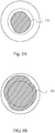
- the camera B detects a lightness and profile of the molten pool of the machined surface by the camera B, and provide the detected lightness and profile of the molten pool to the computer numerical control unit 40. If the lightness and profile of the molten pool is under a default condition (as shown in Fig 3A , showing a profile 210 of the molten pool is detected by the camera B, wherein a dotted line indicates a default size of the molten pool), the power of the laser cladding tool head 20 is increased; and if the lightness and profile of the molten pool is over the default condition (as shown in Fig 3B , showing a profile 220 of the molten pool is detected by the camera B, wherein a dotted line indicates the default size of the molten pool), the power of the laser cladding tool head 20 is decreased.
- a default condition as shown in Fig 3A , showing a profile 210 of the molten pool is detected by the camera B, wherein a dotted line indicates
- the hybrid CNC machining center further comprises a contact or non-contact type detecting tool head 60; and the cladding operation further includes a contact or non-contact type detecting operation S133. If a completeness of the cladded machined surface is achieved, a following step is processed; and if the completeness of the cladded machined surface is not achieved, a cladding operation (step S134) is processed again.
- the laser surface heat treatment tool head 30 further includes a temperature sensor 31, and the surface heat treatment operation S15 further includes a detecting step of a temperature of a machined surface.
- the step of processing the heat treatment operation S15 detect a temperature of the machined surface by the temperature sensor 31, and provide the detected temperature of the machined surface to the computer numerical control unit 40. If the temperature of the machined surface is under a default temperature, a power of the laser surface heat treatment tool head 30 is increased; and if the temperature of the machined surface is over the default temperature, the power of the laser surface heat treatment tool head 30 is decreased.
- the hybrid CNC machining center 100 simultaneously includes the cutting tool head 10, the laser cladding tool head 20, and the laser surface heat treatment tool head 30, so that it can alternately process machining operations.
- a mode is partially damaged to be repaired, firstly cut the damaged place to be flat in the first cutting operation of S12; then add enough volume of the mode in the cladding operation of S13; next finish the repair of the mode in the second cutting operation of S14; and process a partial surface heat treatment in the surface heat treatment operation of S15.
- users can accomplish cutting, laser cladding, and laser surface heat treatment operations for the work-piece just in one single machine, so that the work-piece is unnecessary to be moved between different machines. Therefore, the steps and the process time of the machining operations are substantially simplified.
- the hybrid CNC machining center 100 simultaneously includes the temperature sensor A and the camera B, so that it can detect the temperature, lightness and profile of the molten pool, and provide these to the computer numerical control unit 40 to process a feedback control. Therefore, the machining effect and quality of the work-piece are further increased.
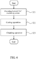
- FIG 4 is a flow chart of a machining method of a hybrid CNC machining center according to a second embodiment of the present invention.
- a machining method of the hybrid CNC machining center according to the second embodiment of the present invention comprises steps of:
- machining method users can accomplish cutting and laser cladding operations for the work-piece just in one single machine, so that the work-piece is unnecessary to be moved between different machines. Therefore, the steps and the process time of the machining operations are substantially simplified. Furthermore, users can flexibly add any other step in the machining method according to the first embodiment of the present invention, so as to increase the machining effect and quality.
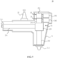
- the laser cladding tool head 20 further comprises: a shell body 21, a shank portion 22 , and a laser module 23, wherein the shank portion 22 is disposed on a top of the shell body 21, and is detachably combined with a tool holder chuck 50 of the above-mentioned hybrid CNC machining center 100; and the laser module 23 includes a laser input portion 231, a laser output portion 232, and a spectroscopic assembly 233, wherein the laser input portion 231 is horizontally disposed on a side surface of the spectroscopic assembly 233, and the laser output portion 232 is perpendicularly disposed on a bottom surface of the spectroscopic assembly 233.
- the spectroscopic assembly 233 has a spectroscope 2330.
- the spectroscope 2330 can be an optical assembly which has a beam split function, such as a prism or a half reflecting mirror.
- the laser cladding tool head further includes a first sensing module 24 and a second sensing module 25, which are disposed above the spectroscopic assembly 233 of the laser module 23, respectively.
- the first sensing module 24 includes a first optical assembly 241 and a first sensing element 242, wherein the first optical assembly 241 has a half reflecting mirror 2410 disposed above the spectroscopic assembly 233 of the laser module 23; and the first sensing element 242 is disposed beside the first optical assembly 241.
- the second sensing module 25 includes a second optical assembly 251 and a second sensing element 252, wherein the second optical assembly 251 has a total reflecting mirror 2510 disposed above the first optical assembly 241 of the first sensing module 24; and the second sensing element 252 is disposed beside the second optical assembly 251.
- an exterior laser source (not shown) horizontally inputs a laser beam R1 through the laser input portion 231, the laser beam is reflected downward through the spectroscope 2330 to be a laser beam R2, and then the laser beam R2 is outputted to a work-piece 200 through the laser output portion 232.
- a sensing (direction) of the first sensing module 24 is reflected downward through the half reflecting mirror 2410 to passes through the spectroscope 2330, (namely, the surface of the work-piece 200 is reflected upward a light beam L1, passes through the spectroscope 2330, and then is reflected through the half reflecting mirror 2410 to be a light beam L2 delivered to the first sensing module 24), so that the first sensing module 24 can detect a situation of a machined surface of the work-piece 200.
- a sensing (direction) of the second sensing module 25 is reflected downward through the total reflecting mirror 2510 to passes through the half reflecting mirror 2410 and the spectroscope 2330, orderly, (namely, the surface of the work-piece 200 is reflected upward a light beam L1, firstly passes through the spectroscope 2330, and next passes through the half reflecting mirror 2410, and then is reflected through the total reflecting mirror 2510 to be a light beam L3 delivered to the second sensing module 25), so that the second sensing module 25 can detect the situation of the machined surface of the work-piece 200.
- one end of the laser input portion 231 is connected to a side surface of the spectroscopic assembly 233, and the other end thereof is disposed on a side surface of the shell body 21 to form a laser entrance 211; and one end of the laser output portion 232 is connected to a bottom surface of the spectroscopic assembly 233, and the other end thereof is disposed on a bottom surface of the shell body 21 to form a laser exit 212.
- the half reflecting mirror 2410 of the first optical assembly 241 is disposed with a 45 degree inclination
- the total reflecting mirror 2510 of the second optical assembly 251 is disposed with a 45 degree inclination.
- the first sensing element 242 of the first sensing module 24 is a temperature sensor, namely the temperature sensor A according to the first embodiment of the present invention; and the second sensing element 252 of the second sensing module 25 is a camera; namely the camera B according to the first embodiment of the present invention.
- the first sensing element 242 of the first sensing module 24 is a camera, namely the camera B according to the first embodiment of the present invention; and the second sensing element 252 of the second sensing module 25 is a temperature sensor, namely the temperature sensor A according to the first embodiment of the present invention.
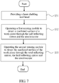
- Fig 7 is a flow chart of a machined surface sensing method of the laser cladding tool head according to the third embodiment of the present invention.
- the machined surface sensing method of the laser cladding tool head comprises steps of:
- the first sensing module 24 can be a temperature sensor module, and the second sensing module 25 can a camera sensor module.
- the first sensing module 24 can be a camera sensor module, and the second sensing module 25 can a temperature sensor module.
- the steps S32 and S33 can be changed their order, or to be executed alone. According to an actual requirement, users can flexibly adjust it, and apply it to the first and second embodiment of the present invention, not limited in the present invention.
- the present invention provides the laser cladding tool head and the machined surface sensing method thereof, by the laser cladding tool head simultaneously including a temperature sensing module and a camera sensing module, the laser cladding tool head can sense the temperature, lightness, and profile of a molten pool, and then provide them to a computer numerical control unit for a feedback control, so as to increase the processing effect and quality of a work-piece.
Landscapes
- Physics & Mathematics (AREA)
- Optics & Photonics (AREA)
- Engineering & Computer Science (AREA)
- Plasma & Fusion (AREA)
- Mechanical Engineering (AREA)
- Life Sciences & Earth Sciences (AREA)
- Health & Medical Sciences (AREA)
- Chemical & Material Sciences (AREA)
- Analytical Chemistry (AREA)
- Biochemistry (AREA)
- General Health & Medical Sciences (AREA)
- General Physics & Mathematics (AREA)
- Immunology (AREA)
- Pathology (AREA)
- Laser Beam Processing (AREA)
Applications Claiming Priority (2)
| Application Number | Priority Date | Filing Date | Title |
|---|---|---|---|
| CN201510208054.1A CN106148946A (zh) | 2015-04-28 | 2015-04-28 | 激光熔覆工具头及其加工表面感测方法 |
| PCT/CN2015/078367 WO2016172992A1 (zh) | 2015-04-28 | 2015-05-06 | 激光熔覆工具头及其加工表面感测方法 |
Publications (2)
| Publication Number | Publication Date |
|---|---|
| EP3290545A1 true EP3290545A1 (de) | 2018-03-07 |
| EP3290545A4 EP3290545A4 (de) | 2019-02-20 |
Family
ID=57198915
Family Applications (1)
| Application Number | Title | Priority Date | Filing Date |
|---|---|---|---|
| EP15890372.4A Withdrawn EP3290545A4 (de) | 2015-04-28 | 2015-05-06 | Laserauftragsschweisswerkzeugkopf und verfahren zur abtastung der zu bearbeitenden oberfläche |
Country Status (7)
| Country | Link |
|---|---|
| US (1) | US20170304938A1 (de) |
| EP (1) | EP3290545A4 (de) |
| CN (1) | CN106148946A (de) |
| CA (1) | CA2956849C (de) |
| MY (1) | MY190911A (de) |
| SG (1) | SG11201610376WA (de) |
| WO (1) | WO2016172992A1 (de) |
Families Citing this family (11)
| Publication number | Priority date | Publication date | Assignee | Title |
|---|---|---|---|---|
| CN106498389B (zh) * | 2016-11-10 | 2018-10-09 | 暨南大学 | 基于多焦点透镜产生预热和缓冷光的激光熔覆装置 |
| DE102017210098B4 (de) * | 2017-06-16 | 2024-03-21 | Jenoptik Optical Systems Gmbh | Scanvorrichtung mit einer Scankopfvorrichtung zum Reflektieren oder Transmittieren von Strahlen für einen Scanner sowie Verfahren zum Reflektieren oder Transmittieren von Strahlen für einen Scanner |
| CN108544238B (zh) * | 2018-06-19 | 2023-12-05 | 亚琛联合科技(天津)有限公司 | 一种高速激光熔覆与车削复合一体机装置 |
| US11331754B2 (en) * | 2018-11-26 | 2022-05-17 | The Boeing Company | Additive manufacturing apparatus and system with a part detachment assembly, and method of using the same |
| CN109518182A (zh) * | 2018-12-29 | 2019-03-26 | 共聚生化科技(昆山)有限公司 | 模具磨损修整方法 |
| CN110340516A (zh) * | 2019-06-21 | 2019-10-18 | 苏州市长峰激光技术有限公司 | 一种基于温度检测的激光加工设备及加工方法 |
| CN110497210A (zh) * | 2019-09-18 | 2019-11-26 | 北京荣盛时代科技发展有限公司 | 一种多功能智能表面处理中心装置和方法 |
| CN111692968B (zh) * | 2020-07-27 | 2021-10-29 | 上海威研精密科技有限公司 | 一种微细铣刀在机多视角视觉检测仪及其检测方法 |
| CN112080740B (zh) * | 2020-09-11 | 2025-03-21 | 陕西天元智能再制造股份有限公司 | 一种带温度显示的熔覆头保护镜抽屉装置 |
| CN113621961A (zh) * | 2021-08-09 | 2021-11-09 | 南京天弓透平科技有限公司 | 一种激光熔覆巴氏合金修复工业透平轴瓦的方法 |
| CN114686877A (zh) * | 2022-03-03 | 2022-07-01 | 武汉点金激光科技有限公司 | 一种轴类件激光熔覆机及激光熔覆加工系统 |
Family Cites Families (16)
| Publication number | Priority date | Publication date | Assignee | Title |
|---|---|---|---|---|
| JPS58218291A (ja) * | 1982-06-11 | 1983-12-19 | Matsushita Electric Ind Co Ltd | 消磁回路 |
| JPS59212184A (ja) * | 1983-05-18 | 1984-12-01 | Hitachi Ltd | Co↓2レ−ザ溶接の制御方法 |
| GB2260402A (en) * | 1991-08-24 | 1993-04-14 | Univ Liverpool | Monitoring laser material processing |
| JPH11114741A (ja) * | 1997-10-20 | 1999-04-27 | Kitamura Mach Co Ltd | 複合マシニングセンタ |
| JP4210560B2 (ja) * | 2003-07-03 | 2009-01-21 | パナソニック株式会社 | レーザ溶接モニタリング方法およびレーザ溶接モニタリング装置 |
| JP4431420B2 (ja) * | 2004-02-24 | 2010-03-17 | ヤマザキマザック株式会社 | 工作機械 |
| US9044827B2 (en) * | 2007-05-31 | 2015-06-02 | Dm3D Technology, Llc | Real-time implementation of generalized predictive algorithm for direct metal deposition (DMD) process control |
| CN101318264B (zh) * | 2008-07-07 | 2011-01-12 | 苏州德龙激光有限公司 | 用于晶圆切割的紫外激光加工设备 |
| CN101559629B (zh) * | 2009-05-12 | 2011-08-17 | 苏州德龙激光有限公司 | 应用于led激光切割设备的同轴影像系统 |
| CN102151984B (zh) * | 2011-03-01 | 2015-03-18 | 华中科技大学 | 一种适用于复杂曲面的激光加工方法及装置 |
| DE102011104550B4 (de) * | 2011-06-17 | 2014-04-30 | Precitec Kg | Optische Messvorrichtung zur Überwachung einer Fügenaht, Fügekopf und Laserschweißkopf mit der selben |
| CN103134599A (zh) * | 2011-11-29 | 2013-06-05 | 中国科学院力学研究所 | 激光金属直接成形中熔池状态实时监测方法和系统 |
| CN102513694B (zh) * | 2011-11-30 | 2015-08-19 | 华中科技大学 | 一种带有刀柄的激光加工机构 |
| CN103008967B (zh) * | 2012-12-20 | 2015-04-08 | 山东大学 | 基于激光熔覆的再制造加工系统 |
| CN103182605A (zh) * | 2013-03-21 | 2013-07-03 | 常州镭赛科技有限公司 | 激光焊接机 |
| CN103604813B (zh) * | 2013-12-05 | 2016-08-17 | 南京辉锐光电科技有限公司 | 用于激光加工过程的熔池监测装置 |
-
2015
- 2015-04-28 CN CN201510208054.1A patent/CN106148946A/zh active Pending
- 2015-05-06 WO PCT/CN2015/078367 patent/WO2016172992A1/zh not_active Ceased
- 2015-05-06 US US15/514,433 patent/US20170304938A1/en not_active Abandoned
- 2015-05-06 EP EP15890372.4A patent/EP3290545A4/de not_active Withdrawn
- 2015-05-06 MY MYPI2017700015A patent/MY190911A/en unknown
- 2015-05-06 CA CA2956849A patent/CA2956849C/en active Active
- 2015-05-06 SG SG11201610376WA patent/SG11201610376WA/en unknown
Also Published As
| Publication number | Publication date |
|---|---|
| SG11201610376WA (en) | 2017-01-27 |
| US20170304938A1 (en) | 2017-10-26 |
| CA2956849A1 (en) | 2016-11-03 |
| EP3290545A4 (de) | 2019-02-20 |
| CA2956849C (en) | 2018-12-04 |
| WO2016172992A1 (zh) | 2016-11-03 |
| CN106148946A (zh) | 2016-11-23 |
| MY190911A (en) | 2022-05-18 |
Similar Documents
| Publication | Publication Date | Title |
|---|---|---|
| CA2956849C (en) | Laser cladding tool head and machined surface sensing method thereof | |
| US10067494B2 (en) | Hybrid computer numerical control machining center and machining method thereof | |
| US11612963B2 (en) | Laser cutting device including machining condition tables and laser cutting method thereof | |
| EP3600838B1 (de) | Werkzeugmaschine | |
| US11331748B2 (en) | Method for machining a cutting insert and corresponding device for machining a cutting insert | |
| US9612594B2 (en) | Method for determining a machining means in hybrid ultraprecision machining device, and hybrid ultraprecision machining device | |
| US11504802B2 (en) | Multifunctional laser processing apparatus | |
| CN109514181B (zh) | 用于制造切削工具的方法和机器设备 | |
| US20180161926A1 (en) | Combined machining apparatus and laser spectroscopic device thereof | |
| US10092976B2 (en) | Machining metal removal control | |
| Thombansen et al. | Setup and maintenance of manufacturing quality in CO2 laser cutting | |
| EP3556509B1 (de) | Kombinierte bearbeitungsmaschine mit einem laserstrahlteiler | |
| TWI540403B (zh) | 雷射熔覆工具頭及其加工表面感測方法 | |
| CN108890321A (zh) | 自动加工系统和机床 | |
| RU164382U1 (ru) | Лазерная технологическая установка для размерной обработки | |
| TWI602635B (zh) | 複合式電腦數値控制加工機及其加工方法 | |
| KR102883674B1 (ko) | 공작기계의 척킹장치 및 이의 제어방법 | |
| TWI610750B (zh) | 複合加工之加工機及其雷射分光裝置 | |
| JPH11226847A (ja) | 刃具自動交換手段を備えた金属加工装置の稼動方法 |
Legal Events
| Date | Code | Title | Description |
|---|---|---|---|
| STAA | Information on the status of an ep patent application or granted ep patent |
Free format text: STATUS: THE INTERNATIONAL PUBLICATION HAS BEEN MADE |
|
| PUAI | Public reference made under article 153(3) epc to a published international application that has entered the european phase |
Free format text: ORIGINAL CODE: 0009012 |
|
| STAA | Information on the status of an ep patent application or granted ep patent |
Free format text: STATUS: REQUEST FOR EXAMINATION WAS MADE |
|
| 17P | Request for examination filed |
Effective date: 20170106 |
|
| AK | Designated contracting states |
Kind code of ref document: A1 Designated state(s): AL AT BE BG CH CY CZ DE DK EE ES FI FR GB GR HR HU IE IS IT LI LT LU LV MC MK MT NL NO PL PT RO RS SE SI SK SM TR |
|
| AX | Request for extension of the european patent |
Extension state: BA ME |
|
| DAV | Request for validation of the european patent (deleted) | ||
| DAX | Request for extension of the european patent (deleted) | ||
| A4 | Supplementary search report drawn up and despatched |
Effective date: 20190117 |
|
| RIC1 | Information provided on ipc code assigned before grant |
Ipc: B23K 26/03 20060101ALI20190111BHEP Ipc: C23C 24/10 20060101AFI20190111BHEP Ipc: C21D 9/50 20060101ALI20190111BHEP Ipc: G01N 21/00 20060101ALI20190111BHEP Ipc: B23K 26/00 20140101ALI20190111BHEP Ipc: B23K 26/06 20140101ALI20190111BHEP Ipc: B23K 26/34 20140101ALI20190111BHEP Ipc: G01N 21/84 20060101ALI20190111BHEP |
|
| STAA | Information on the status of an ep patent application or granted ep patent |
Free format text: STATUS: THE APPLICATION IS DEEMED TO BE WITHDRAWN |
|
| 18D | Application deemed to be withdrawn |
Effective date: 20190817 |