EP3290532A1 - Bottom-blowing plug with improved workability - Google Patents
Bottom-blowing plug with improved workability Download PDFInfo
- Publication number
- EP3290532A1 EP3290532A1 EP15910651.7A EP15910651A EP3290532A1 EP 3290532 A1 EP3290532 A1 EP 3290532A1 EP 15910651 A EP15910651 A EP 15910651A EP 3290532 A1 EP3290532 A1 EP 3290532A1
- Authority
- EP
- European Patent Office
- Prior art keywords
- furnace
- plug
- bending
- folding
- gas
- Prior art date
- Legal status (The legal status is an assumption and is not a legal conclusion. Google has not performed a legal analysis and makes no representation as to the accuracy of the status listed.)
- Granted
Links
Images
Classifications
-
- C—CHEMISTRY; METALLURGY
- C21—METALLURGY OF IRON
- C21C—PROCESSING OF PIG-IRON, e.g. REFINING, MANUFACTURE OF WROUGHT-IRON OR STEEL; TREATMENT IN MOLTEN STATE OF FERROUS ALLOYS
- C21C5/00—Manufacture of carbon-steel, e.g. plain mild steel, medium carbon steel or cast steel or stainless steel
- C21C5/28—Manufacture of steel in the converter
- C21C5/42—Constructional features of converters
- C21C5/46—Details or accessories
- C21C5/48—Bottoms or tuyéres of converters
-
- C—CHEMISTRY; METALLURGY
- C21—METALLURGY OF IRON
- C21C—PROCESSING OF PIG-IRON, e.g. REFINING, MANUFACTURE OF WROUGHT-IRON OR STEEL; TREATMENT IN MOLTEN STATE OF FERROUS ALLOYS
- C21C7/00—Treating molten ferrous alloys, e.g. steel, not covered by groups C21C1/00 - C21C5/00
- C21C7/04—Removing impurities by adding a treating agent
- C21C7/072—Treatment with gases
-
- F—MECHANICAL ENGINEERING; LIGHTING; HEATING; WEAPONS; BLASTING
- F27—FURNACES; KILNS; OVENS; RETORTS
- F27B—FURNACES, KILNS, OVENS OR RETORTS IN GENERAL; OPEN SINTERING OR LIKE APPARATUS
- F27B3/00—Hearth-type furnaces, e.g. of reverberatory type; Electric arc furnaces ; Tank furnaces
- F27B3/10—Details, accessories or equipment, e.g. dust-collectors, specially adapted for hearth-type furnaces
- F27B3/22—Arrangements of air or gas supply devices
-
- F—MECHANICAL ENGINEERING; LIGHTING; HEATING; WEAPONS; BLASTING
- F27—FURNACES; KILNS; OVENS; RETORTS
- F27D—DETAILS OR ACCESSORIES OF FURNACES, KILNS, OVENS OR RETORTS, IN SO FAR AS THEY ARE OF KINDS OCCURRING IN MORE THAN ONE KIND OF FURNACE
- F27D27/00—Stirring devices for molten material
-
- F—MECHANICAL ENGINEERING; LIGHTING; HEATING; WEAPONS; BLASTING
- F27—FURNACES; KILNS; OVENS; RETORTS
- F27D—DETAILS OR ACCESSORIES OF FURNACES, KILNS, OVENS OR RETORTS, IN SO FAR AS THEY ARE OF KINDS OCCURRING IN MORE THAN ONE KIND OF FURNACE
- F27D3/00—Charging; Discharging; Manipulation of charge
- F27D3/16—Introducing a fluid jet or current into the charge
- F27D2003/161—Introducing a fluid jet or current into the charge through a porous element
-
- F—MECHANICAL ENGINEERING; LIGHTING; HEATING; WEAPONS; BLASTING
- F27—FURNACES; KILNS; OVENS; RETORTS
- F27D—DETAILS OR ACCESSORIES OF FURNACES, KILNS, OVENS OR RETORTS, IN SO FAR AS THEY ARE OF KINDS OCCURRING IN MORE THAN ONE KIND OF FURNACE
- F27D3/00—Charging; Discharging; Manipulation of charge
- F27D3/16—Introducing a fluid jet or current into the charge
- F27D2003/167—Introducing a fluid jet or current into the charge the fluid being a neutral gas
-
- F—MECHANICAL ENGINEERING; LIGHTING; HEATING; WEAPONS; BLASTING
- F27—FURNACES; KILNS; OVENS; RETORTS
- F27D—DETAILS OR ACCESSORIES OF FURNACES, KILNS, OVENS OR RETORTS, IN SO FAR AS THEY ARE OF KINDS OCCURRING IN MORE THAN ONE KIND OF FURNACE
- F27D27/00—Stirring devices for molten material
- F27D2027/002—Gas stirring
Definitions
- the present invention relates to a gas-injecting plug for molten metal. Specifically, it relates to a bottom-blowing plug that is aimed at injecting a gas into a metallic molten metal in a converter furnace, and the like, and which is to be built in into a bottom wall of the converter furnace, and so forth.
- the bottom portion of a converter furnace makes such a rough or simplified structure as illustrated in a vertical end-face diagram shown in Fig. 4 .
- 10 designates an iron cladding of the bottom part of a furnace
- 20 designates a tuyere for injecting a gas.
- a permanent brick 9 is lined on the iron cladding 10 of the furnace-bottom part, and then a working brick 5 is laminated on this permanent brick 9.
- the above-mentioned working brick 5 is available in such an instance that it makes a double-layer lining by a lower-layer brick 5b and an upper-layer brick 5a, as shown in Fig.
- Patent Literature No. 1 Japanese Unexamined Patent Publication (KOKAI) Gazette No. 5-70819
- a refractory brick for converter furnace Since a refractory brick for converter furnace is exposed to high-temperature molten metals to be corroded, it needs to undergo relining regularly.
- relining the converter-furnace bricks it has been carried out to line bricks in the vertical direction and horizontal direction from a predetermined positon in the iron cladding; or, in a certain case, they are lined concentrically about the predetermined position serving as the center.
- the bottom-blowing plug is built in at a location, which is close to a position disposed, depending on the lining order of the refractory bricks, in the iron cladding, to let a gas supply conduit of the bottom-blowing plug pass through it.
- the refractory bricks are exchanged for the other refractory bricks, or operations are done to adjust the position of the bottom-blowing plugs by scraping or grinding off some of the refractory bricks.
- Such operations require a considerable time, so that such another inconvenience might possibly arise that the time for maintaining or repairing a converter furnace has become longer.
- the present invention has been made in view of the above-mentioned problems. Hence, it is an assignment to the present invention to provide a bottom-blowing plug, which can be easily or readily built in into the bottom of a furnace, such as a converter furnace.
- a bottom-blowing plug which is made to solve the assignment, comprises: a plug body for spouting a gas, the plug body disposed in a furnace-bottom refractory for the bottom of a furnace, such as a converter furnace; and a gas supply conduit for supplying the gas to the plug body, some or all of the gas supply conduit including a bending/folding-free conduit.
- the gas supply conduit includes a bending/folding-free conduit, it is possible to insert the gas supply conduit easily or readily into a hole in an iron cladding into which the gas supply conduit is to be inserted. As a result, it is possible to build in the bottom-blowing plug easily or readily into the furnace bottom.
- the bending/folding-free conduit can preferably include a flexible hose and/or a bellows. Note that the bending/folding-free conduit needs to exhibit heat resistance, pressure resistance, and airtightness.
- the plug body can preferably have a sector-type horizontal cross-sectional configuration.
- the plug body can preferably be equipped with multiple through bores.
- the bores, through which a gas is to be injected come not to be clogged or blocked by a molten metal.
- the gas supply conduit includes a bending/folding-free conduit, it is possible to insert the gas supply conduit easily or readily into a hole, into which the gas supply conduit is to be inserted, in an iron cladding of a converter furnace.
- a bottom-blowing plug that is disposed in a furnace-bottom refractory for the bottom of a furnace, such as a converter furnace, will be described concretely with reference to Figs. 1 and 2 .
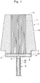
- a bottom-blowing plug As illustrated in Fig. 1 , a bottom-blowing plug according to the embodiment is constituted of a plug body 1 provided with multiple through bores 11, and a bending/folding-free conduit 2 installed to a downside of the plug body 1.
- the plug body 1 is formed as a trapezoidal shape whose upper side is made smaller and lower side is made larger in the vertical cross section, and comprises a flat upper face 13, which faces opposite to a molten metal in the converter furnace, a lower face 12, and an outer peripheral face 14.
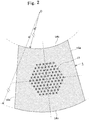
- the outer peripheral face 14 of the plug body 1 includes two flat faces 14a, and curved faces (14b, 14c).
- the curved face 14b makes an arc of a circle whose center is a furnace-core center "O" of the converter furnace and which has a radius "R 0 ,” whereas the curved face 14c makes an arc of another circle whose center is the furnace-core center "O” and which has a radius "R 1 " (> "R 0 ").
- Abase 3, which forms a gas chamber 31, is attached onto the lower face 12 of the plug body 1.
- the gas chamber 31, to which the lower portion of the through bores 11 opens, is disposed in the downside of the plug body 1, and the bending/folding-free conduit 2 communicates with the gas chamber 31.
- a long-service-life or highly-durable magnesia/carbonaceous material is desirable.
- the through bores 11 have a horizontal cross-sectional configuration formed as a circular shape, and are additionally disposed to elongate along the axial center line of the plug body 1. Moreover, the respective bores 11 open not only in the top face 13 of the plug body 11 but also in the bottom face 12, and accordingly make it possible to inject a gas into a molten metal.
- 90 pieces of the through bores 11 are arranged at equal intervals on 6 pieces of imaginary concentric regular hexagons.
- the gas chamber 31 is formed by plugging the cylinder-shaped base 3 at the downside with a disk 4.
- An installation port 41 which is arranged concentrically with the plug body 1, is disposed fixedly onto the disk 4 at the center.
- 5 designates a metallic disk coming in contact with the lower face 12 of the plug body 1.
- the bending/folding-free conduit 2 which is made of metal, comprises a thin-thickness pipe 21, and a member 22 wound spirally around the pipe 21 on the outer periphery; and excels in the heat resistance, pressure resistance and airtightness.
- the spirally-wound member 22 operates to retain a circular cross section even when the thin-thickness pipe 21 bends.
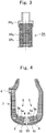
- the bending/folding-free conduit 2 can also be a flexible hose 2A shown in Fig. 3 .
- the flexible hose 2A is made by covering the outer periphery of a core tube 2A 1 , which is made of stainless steel, with an over braid 2A 2 , which is made of stainless steel. Note that 2A 3 designates an end connection made of stainless steel.
- the core tube 2A 1 is a kind of bellows, and the over braid 2A 2 is a fabric made of stainless-steel wire.
- the flexible hose 2A is superior to the bending/holding-free conduit 2 in the bending/folding property, heat resistance, pressure resistance, and airtightness.
- the bending/folding-free conduit 2 can even be a bellows.
- the gas supply conduit 2 which communicates with the gas chamber 31 includes a bending/folding-free conduit, some of it can also include the bending/folding-free conduit partially.
- a gas supply conduit which supplies a gas to the through bores 11 in the plug body 1, comprises the bending/folding-free conduit 2, the gas supply conduit can be inserted easily or readily into a hole in a converter furnace's iron cladding into which the gas supply conduit is to be inserted.
- the injection plug according to the embodiment comprises: the curved face 14b making an arc of a circle whose center is the furnace-core center "O" of a converter furnace and which has a radius "R 0 "; and the curved face 14c making an arc of another circle whose center is the furnace-core center “O” and which has a radius "R 1 " (> "R 0 "), it becomes easy or ready to build in a bottom-blowing plug so as to enclose a furnace core while making the furnace core serve as the center.
Landscapes
- Engineering & Computer Science (AREA)
- Chemical & Material Sciences (AREA)
- Mechanical Engineering (AREA)
- General Engineering & Computer Science (AREA)
- Materials Engineering (AREA)
- Metallurgy (AREA)
- Organic Chemistry (AREA)
- Manufacturing & Machinery (AREA)
- Carbon Steel Or Casting Steel Manufacturing (AREA)
- Treatment Of Steel In Its Molten State (AREA)
Abstract
Description
- The present invention relates to a gas-injecting plug for molten metal. Specifically, it relates to a bottom-blowing plug that is aimed at injecting a gas into a metallic molten metal in a converter furnace, and the like, and which is to be built in into a bottom wall of the converter furnace, and so forth.
- In converter furnaces, it has been heretofore carried out conventionally to inject a gas from a bottom-blowing plug, which is buried in the bottom portion of a converter furnace, in order to facilitate refining or stir molten steel, and the like.
- The bottom portion of a converter furnace makes such a rough or simplified structure as illustrated in a vertical end-face diagram shown in
Fig. 4 . 10 designates an iron cladding of the bottom part of a furnace, and 20 designates a tuyere for injecting a gas. Apermanent brick 9 is lined on the iron cladding 10 of the furnace-bottom part, and then a workingbrick 5 is laminated on thispermanent brick 9. Moreover, the above-mentioned workingbrick 5 is available in such an instance that it makes a double-layer lining by a lower-layer brick 5b and an upper-layer brick 5a, as shown inFig. 4 ; or in such another instance that it makes a one-layer lining by employing a long-length brick having a layer thickness to an extent of the upper and lower two layers. In the drawing, 6 designates a long-length integrated brick forming the tuyere, 7 designates a trunk portion of the furnace, and 8 designates a tapping port (see Patent Literature No. 1, for instance). - Patent Literature No. 1: Japanese Unexamined Patent Publication (KOKAI) Gazette No.
5-70819 - Since a refractory brick for converter furnace is exposed to high-temperature molten metals to be corroded, it needs to undergo relining regularly. When relining the converter-furnace bricks, it has been carried out to line bricks in the vertical direction and horizontal direction from a predetermined positon in the iron cladding; or, in a certain case, they are lined concentrically about the predetermined position serving as the center.
- With regard to a bottom-blowing plug as well, the bottom-blowing plug is built in at a location, which is close to a position disposed, depending on the lining order of the refractory bricks, in the iron cladding, to let a gas supply conduit of the bottom-blowing plug pass through it.
- There might possibly occur a case where such an inconvenience arises that the gas supply conduit of the bottom-blowing plug does not come into a hole for the gas-supply conduit in the iron cladding because of errors occurring at the time of lining and sticking the refractory bricks. In particular, when working with multiple plugs in the case where they are an interpolation (or inner-insertion) type bottom-blowing plug, respectively, the inconvenience might possibly arise so that the gas supply conduit of the bottom-blowing plugs does not come into the hole in the iron cladding because the hole in the iron cladding is small at the tuyere (see
Fig. 4 ). If such is the case, the refractory bricks are exchanged for the other refractory bricks, or operations are done to adjust the position of the bottom-blowing plugs by scraping or grinding off some of the refractory bricks. However, such operations require a considerable time, so that such another inconvenience might possibly arise that the time for maintaining or repairing a converter furnace has become longer. - The present invention has been made in view of the above-mentioned problems. Hence, it is an assignment to the present invention to provide a bottom-blowing plug, which can be easily or readily built in into the bottom of a furnace, such as a converter furnace.
- A bottom-blowing plug according to the present invention, which is made to solve the assignment, comprises: a plug body for spouting a gas, the plug body disposed in a furnace-bottom refractory for the bottom of a furnace, such as a converter furnace; and a gas supply conduit for supplying the gas to the plug body, some or all of the gas supply conduit including a bending/folding-free conduit.
- Since some or all of the gas supply conduit includes a bending/folding-free conduit, it is possible to insert the gas supply conduit easily or readily into a hole in an iron cladding into which the gas supply conduit is to be inserted. As a result, it is possible to build in the bottom-blowing plug easily or readily into the furnace bottom.
- In the aforementioned bottom-blowing plug, the bending/folding-free conduit can preferably include a flexible hose and/or a bellows. Note that the bending/folding-free conduit needs to exhibit heat resistance, pressure resistance, and airtightness.
- Moreover, the plug body can preferably have a sector-type horizontal cross-sectional configuration. Thus, it becomes easy or ready to build in the bottom-blowing plug so as to enclose a furnace core while making the furnace core serve as the center.
- In addition, the plug body can preferably be equipped with multiple through bores. Thus, the bores, through which a gas is to be injected, come not to be clogged or blocked by a molten metal.
- Since some or all of the gas supply conduit includes a bending/folding-free conduit, it is possible to insert the gas supply conduit easily or readily into a hole, into which the gas supply conduit is to be inserted, in an iron cladding of a converter furnace.
-
-
Fig. 1 is a vertical cross-sectional diagram of a bottom-blowing plug according to an embodiment of the present invention; -
Fig. 2 is a horizontal cross-sectional diagram of the bottom-blowing plug according to the embodiment of the present invention; -
Fig. 3 is a partial end-face view diagram illustrating a modified embodiment of a bending/folding-free conduit; and -
Fig. 4 is a vertical cross-sectional diagram illustrating a rough or simplified structure of a converter furnace at the bottom. - Hereinafter, an embodiment according to the present invention, a bottom-blowing plug that is disposed in a furnace-bottom refractory for the bottom of a furnace, such as a converter furnace, will be described concretely with reference to
Figs. 1 and2 . - As illustrated in
Fig. 1 , a bottom-blowing plug according to the embodiment is constituted of aplug body 1 provided with multiple throughbores 11, and a bending/folding-free conduit 2 installed to a downside of theplug body 1. - The
plug body 1 is formed as a trapezoidal shape whose upper side is made smaller and lower side is made larger in the vertical cross section, and comprises a flatupper face 13, which faces opposite to a molten metal in the converter furnace, alower face 12, and an outerperipheral face 14. As illustrated inFig. 2 , the outerperipheral face 14 of theplug body 1 includes twoflat faces 14a, and curved faces (14b, 14c). Thecurved face 14b makes an arc of a circle whose center is a furnace-core center "O" of the converter furnace and which has a radius "R0," whereas thecurved face 14c makes an arc of another circle whose center is the furnace-core center "O" and which has a radius "R1" (> "R0"). -
Abase 3, which forms agas chamber 31, is attached onto thelower face 12 of theplug body 1. Thegas chamber 31, to which the lower portion of thethrough bores 11 opens, is disposed in the downside of theplug body 1, and the bending/folding-free conduit 2 communicates with thegas chamber 31. - For a refractory material quality of the
plug body 1, a long-service-life or highly-durable magnesia/carbonaceous material is desirable. - As illustrated in
Fig. 2 , thethrough bores 11 have a horizontal cross-sectional configuration formed as a circular shape, and are additionally disposed to elongate along the axial center line of theplug body 1. Moreover, the respective bores 11 open not only in thetop face 13 of theplug body 11 but also in thebottom face 12, and accordingly make it possible to inject a gas into a molten metal. In theplug body 1 according to the present embodiment, 90 pieces of thethrough bores 11 are arranged at equal intervals on 6 pieces of imaginary concentric regular hexagons. - (> The
gas chamber 31 is formed by plugging the cylinder-shaped base 3 at the downside with adisk 4. Aninstallation port 41, which is arranged concentrically with theplug body 1, is disposed fixedly onto thedisk 4 at the center. Note that 5 designates a metallic disk coming in contact with thelower face 12 of theplug body 1. - Onto the
installation port 41, one of the opposite ends of the bending/folding-free conduit 2 is connected in series. The bending/folding-free conduit 2, which is made of metal, comprises a thin-thickness pipe 21, and amember 22 wound spirally around thepipe 21 on the outer periphery; and excels in the heat resistance, pressure resistance and airtightness. The spirally-wound member 22 operates to retain a circular cross section even when the thin-thickness pipe 21 bends. - The bending/folding-
free conduit 2 can also be aflexible hose 2A shown inFig. 3 . Theflexible hose 2A is made by covering the outer periphery of acore tube 2A1, which is made of stainless steel, with an overbraid 2A2, which is made of stainless steel. Note that 2A3 designates an end connection made of stainless steel. Thecore tube 2A1 is a kind of bellows, and the overbraid 2A2 is a fabric made of stainless-steel wire. - The
flexible hose 2A is superior to the bending/holding-free conduit 2 in the bending/folding property, heat resistance, pressure resistance, and airtightness. - (> The bending/folding-
free conduit 2 can even be a bellows. - In the bottom-blowing plug according to the present embodiment, although all of the
gas supply conduit 2, which communicates with thegas chamber 31, includes a bending/folding-free conduit, some of it can also include the bending/folding-free conduit partially. - In an injection plug according to the embodiment, since a gas supply conduit, which supplies a gas to the
through bores 11 in theplug body 1, comprises the bending/folding-free conduit 2, the gas supply conduit can be inserted easily or readily into a hole in a converter furnace's iron cladding into which the gas supply conduit is to be inserted. - Moreover, since the injection plug according to the embodiment comprises: the
curved face 14b making an arc of a circle whose center is the furnace-core center "O" of a converter furnace and which has a radius "R0"; and thecurved face 14c making an arc of another circle whose center is the furnace-core center "O" and which has a radius "R1" (> "R0"), it becomes easy or ready to build in a bottom-blowing plug so as to enclose a furnace core while making the furnace core serve as the center. -
- 1: Plug Body;
- 2: Bending/folding-free Conduit;
- 2A: Flexible Hose
Claims (2)
- A bottom-blowing plug comprising: a plug body for spouting a gas, the plug body disposed in a furnace-bottom refractory for the bottom of a furnace, such as a converter furnace; and a gas supply conduit for supplying the gas to the plug body, some or all of the gas supply conduit including a bending/folding-free conduit.
- The bottom-blowing plug as set forth in claim 1, wherein the bending/folding-free conduit includes a flexible hose and/or a bellows.
Applications Claiming Priority (1)
| Application Number | Priority Date | Filing Date | Title |
|---|---|---|---|
| PCT/JP2015/006284 WO2017103959A1 (en) | 2015-12-17 | 2015-12-17 | Bottom-blowing plug with improved workability |
Publications (3)
| Publication Number | Publication Date |
|---|---|
| EP3290532A1 true EP3290532A1 (en) | 2018-03-07 |
| EP3290532A4 EP3290532A4 (en) | 2018-05-23 |
| EP3290532B1 EP3290532B1 (en) | 2020-05-06 |
Family
ID=59056488
Family Applications (1)
| Application Number | Title | Priority Date | Filing Date |
|---|---|---|---|
| EP15910651.7A Active EP3290532B1 (en) | 2015-12-17 | 2015-12-17 | Converter furnace with bottom-blowing plug with improved workability |
Country Status (4)
| Country | Link |
|---|---|
| EP (1) | EP3290532B1 (en) |
| JP (1) | JP6563034B2 (en) |
| CN (1) | CN107109502A (en) |
| WO (1) | WO2017103959A1 (en) |
Families Citing this family (1)
| Publication number | Priority date | Publication date | Assignee | Title |
|---|---|---|---|---|
| JP6780115B2 (en) * | 2017-07-11 | 2020-11-04 | 東京窯業株式会社 | Furnace and bottom blowing plug |
Family Cites Families (8)
| Publication number | Priority date | Publication date | Assignee | Title |
|---|---|---|---|---|
| BE567433A (en) * | ||||
| JPS6013405B2 (en) * | 1980-11-14 | 1985-04-06 | 住友金属工業株式会社 | Tuyeres for molten metal smelting |
| JPS60135512A (en) * | 1983-12-26 | 1985-07-18 | Nippon Steel Corp | Oxygen converter |
| US4502670A (en) * | 1984-02-02 | 1985-03-05 | Allied Corporation | Gas hook-up to a ladle |
| JPH0639613B2 (en) * | 1989-06-22 | 1994-05-25 | 日本鋼管株式会社 | Bottom blowing tuyere |
| JPH0941024A (en) * | 1995-05-25 | 1997-02-10 | Japan Casting & Forging Corp | Gas blowing nozzle into molten metal and its using method thereof |
| CN2612676Y (en) * | 2003-04-17 | 2004-04-21 | 攀枝花新钢钒股份有限公司提钒炼钢厂 | Bottom gas supply device of combined blown converter |
| JP2007262471A (en) * | 2006-03-28 | 2007-10-11 | Tokyo Yogyo Co Ltd | Gas blow plug |
-
2015
- 2015-12-17 WO PCT/JP2015/006284 patent/WO2017103959A1/en not_active Ceased
- 2015-12-17 JP JP2017555874A patent/JP6563034B2/en active Active
- 2015-12-17 CN CN201580001389.4A patent/CN107109502A/en active Pending
- 2015-12-17 EP EP15910651.7A patent/EP3290532B1/en active Active
Also Published As
| Publication number | Publication date |
|---|---|
| WO2017103959A1 (en) | 2017-06-22 |
| CN107109502A (en) | 2017-08-29 |
| JPWO2017103959A1 (en) | 2018-09-20 |
| EP3290532B1 (en) | 2020-05-06 |
| EP3290532A4 (en) | 2018-05-23 |
| JP6563034B2 (en) | 2019-09-04 |
Similar Documents
| Publication | Publication Date | Title |
|---|---|---|
| EP3290532A1 (en) | Bottom-blowing plug with improved workability | |
| JP5230693B2 (en) | Gas blowing nozzle | |
| WO2011158607A1 (en) | Circulation tube refractory product for an rh furnace | |
| JP6780115B2 (en) | Furnace and bottom blowing plug | |
| US3829073A (en) | Devices blowing-in oxygen through the bottoms of metallurgical converters | |
| US3819165A (en) | Device for blowing-in oxygen through the refractory lining of a metallurgical converter | |
| US20150321251A1 (en) | Refractory component for lining a metallurgical vessel | |
| JP3894502B2 (en) | Gas injection nozzle for molten metal and method of using the same | |
| KR101419391B1 (en) | Blast furnace having temporary tapping hole and method of performing iron tapping of blast furnace using the same | |
| JPWO1996037632A1 (en) | Nozzle for injecting gas into molten metal and method of using same | |
| JP6691643B1 (en) | Integrated tuyere for converter | |
| CN208108844U (en) | Bonnet and smelting system with it | |
| CN211872026U (en) | Blast furnace taphole structure | |
| CN107299187A (en) | Suppression of eddy current slag entrainment in converter taphole and converter | |
| JP7824512B2 (en) | Gas blowing plug and method for manufacturing the gas blowing plug | |
| JPS6311613A (en) | Construction of bottom blowing tuyere for electric furnace | |
| JP6335052B2 (en) | Steel outlet sleeve | |
| KR100868507B1 (en) | Inert gas blowing device of refinery | |
| RU24466U1 (en) | Converter for steel smelting | |
| JPH0638104Y2 (en) | Gas injection nozzle | |
| JP7096709B2 (en) | Gas blow plug and its mounting structure | |
| JP3713041B1 (en) | Outlet sleeve | |
| TR201815676T4 (en) | Access port configuration and method for creating it. | |
| CN205347495U (en) | High stability RH refining furnace dip pipe inner bag | |
| JP5102678B2 (en) | Upper nozzle |
Legal Events
| Date | Code | Title | Description |
|---|---|---|---|
| STAA | Information on the status of an ep patent application or granted ep patent |
Free format text: STATUS: THE INTERNATIONAL PUBLICATION HAS BEEN MADE |
|
| PUAI | Public reference made under article 153(3) epc to a published international application that has entered the european phase |
Free format text: ORIGINAL CODE: 0009012 |
|
| STAA | Information on the status of an ep patent application or granted ep patent |
Free format text: STATUS: REQUEST FOR EXAMINATION WAS MADE |
|
| 17P | Request for examination filed |
Effective date: 20171128 |
|
| AK | Designated contracting states |
Kind code of ref document: A1 Designated state(s): AL AT BE BG CH CY CZ DE DK EE ES FI FR GB GR HR HU IE IS IT LI LT LU LV MC MK MT NL NO PL PT RO RS SE SI SK SM TR |
|
| AX | Request for extension of the european patent |
Extension state: BA ME |
|
| A4 | Supplementary search report drawn up and despatched |
Effective date: 20180424 |
|
| RIC1 | Information provided on ipc code assigned before grant |
Ipc: C21C 5/48 20060101AFI20180418BHEP Ipc: C21C 7/072 20060101ALI20180418BHEP |
|
| STAA | Information on the status of an ep patent application or granted ep patent |
Free format text: STATUS: EXAMINATION IS IN PROGRESS |
|
| 17Q | First examination report despatched |
Effective date: 20181001 |
|
| DAV | Request for validation of the european patent (deleted) | ||
| DAX | Request for extension of the european patent (deleted) | ||
| GRAP | Despatch of communication of intention to grant a patent |
Free format text: ORIGINAL CODE: EPIDOSNIGR1 |
|
| STAA | Information on the status of an ep patent application or granted ep patent |
Free format text: STATUS: GRANT OF PATENT IS INTENDED |
|
| INTG | Intention to grant announced |
Effective date: 20191217 |
|
| GRAS | Grant fee paid |
Free format text: ORIGINAL CODE: EPIDOSNIGR3 |
|
| GRAA | (expected) grant |
Free format text: ORIGINAL CODE: 0009210 |
|
| STAA | Information on the status of an ep patent application or granted ep patent |
Free format text: STATUS: THE PATENT HAS BEEN GRANTED |
|
| AK | Designated contracting states |
Kind code of ref document: B1 Designated state(s): AL AT BE BG CH CY CZ DE DK EE ES FI FR GB GR HR HU IE IS IT LI LT LU LV MC MK MT NL NO PL PT RO RS SE SI SK SM TR |
|
| REG | Reference to a national code |
Ref country code: GB Ref legal event code: FG4D |
|
| REG | Reference to a national code |
Ref country code: CH Ref legal event code: EP Ref country code: AT Ref legal event code: REF Ref document number: 1266801 Country of ref document: AT Kind code of ref document: T Effective date: 20200515 |
|
| REG | Reference to a national code |
Ref country code: IE Ref legal event code: FG4D |
|
| REG | Reference to a national code |
Ref country code: DE Ref legal event code: R096 Ref document number: 602015052614 Country of ref document: DE |
|
| REG | Reference to a national code |
Ref country code: LT Ref legal event code: MG4D |
|
| REG | Reference to a national code |
Ref country code: NL Ref legal event code: MP Effective date: 20200506 |
|
| PG25 | Lapsed in a contracting state [announced via postgrant information from national office to epo] |
Ref country code: PT Free format text: LAPSE BECAUSE OF FAILURE TO SUBMIT A TRANSLATION OF THE DESCRIPTION OR TO PAY THE FEE WITHIN THE PRESCRIBED TIME-LIMIT Effective date: 20200907 Ref country code: IS Free format text: LAPSE BECAUSE OF FAILURE TO SUBMIT A TRANSLATION OF THE DESCRIPTION OR TO PAY THE FEE WITHIN THE PRESCRIBED TIME-LIMIT Effective date: 20200906 Ref country code: NO Free format text: LAPSE BECAUSE OF FAILURE TO SUBMIT A TRANSLATION OF THE DESCRIPTION OR TO PAY THE FEE WITHIN THE PRESCRIBED TIME-LIMIT Effective date: 20200806 Ref country code: FI Free format text: LAPSE BECAUSE OF FAILURE TO SUBMIT A TRANSLATION OF THE DESCRIPTION OR TO PAY THE FEE WITHIN THE PRESCRIBED TIME-LIMIT Effective date: 20200506 Ref country code: SE Free format text: LAPSE BECAUSE OF FAILURE TO SUBMIT A TRANSLATION OF THE DESCRIPTION OR TO PAY THE FEE WITHIN THE PRESCRIBED TIME-LIMIT Effective date: 20200506 Ref country code: LT Free format text: LAPSE BECAUSE OF FAILURE TO SUBMIT A TRANSLATION OF THE DESCRIPTION OR TO PAY THE FEE WITHIN THE PRESCRIBED TIME-LIMIT Effective date: 20200506 Ref country code: GR Free format text: LAPSE BECAUSE OF FAILURE TO SUBMIT A TRANSLATION OF THE DESCRIPTION OR TO PAY THE FEE WITHIN THE PRESCRIBED TIME-LIMIT Effective date: 20200807 |
|
| PG25 | Lapsed in a contracting state [announced via postgrant information from national office to epo] |
Ref country code: BG Free format text: LAPSE BECAUSE OF FAILURE TO SUBMIT A TRANSLATION OF THE DESCRIPTION OR TO PAY THE FEE WITHIN THE PRESCRIBED TIME-LIMIT Effective date: 20200806 Ref country code: RS Free format text: LAPSE BECAUSE OF FAILURE TO SUBMIT A TRANSLATION OF THE DESCRIPTION OR TO PAY THE FEE WITHIN THE PRESCRIBED TIME-LIMIT Effective date: 20200506 Ref country code: LV Free format text: LAPSE BECAUSE OF FAILURE TO SUBMIT A TRANSLATION OF THE DESCRIPTION OR TO PAY THE FEE WITHIN THE PRESCRIBED TIME-LIMIT Effective date: 20200506 Ref country code: HR Free format text: LAPSE BECAUSE OF FAILURE TO SUBMIT A TRANSLATION OF THE DESCRIPTION OR TO PAY THE FEE WITHIN THE PRESCRIBED TIME-LIMIT Effective date: 20200506 |
|
| REG | Reference to a national code |
Ref country code: AT Ref legal event code: MK05 Ref document number: 1266801 Country of ref document: AT Kind code of ref document: T Effective date: 20200506 |
|
| PG25 | Lapsed in a contracting state [announced via postgrant information from national office to epo] |
Ref country code: AL Free format text: LAPSE BECAUSE OF FAILURE TO SUBMIT A TRANSLATION OF THE DESCRIPTION OR TO PAY THE FEE WITHIN THE PRESCRIBED TIME-LIMIT Effective date: 20200506 Ref country code: NL Free format text: LAPSE BECAUSE OF FAILURE TO SUBMIT A TRANSLATION OF THE DESCRIPTION OR TO PAY THE FEE WITHIN THE PRESCRIBED TIME-LIMIT Effective date: 20200506 |
|
| PG25 | Lapsed in a contracting state [announced via postgrant information from national office to epo] |
Ref country code: DK Free format text: LAPSE BECAUSE OF FAILURE TO SUBMIT A TRANSLATION OF THE DESCRIPTION OR TO PAY THE FEE WITHIN THE PRESCRIBED TIME-LIMIT Effective date: 20200506 Ref country code: ES Free format text: LAPSE BECAUSE OF FAILURE TO SUBMIT A TRANSLATION OF THE DESCRIPTION OR TO PAY THE FEE WITHIN THE PRESCRIBED TIME-LIMIT Effective date: 20200506 Ref country code: SM Free format text: LAPSE BECAUSE OF FAILURE TO SUBMIT A TRANSLATION OF THE DESCRIPTION OR TO PAY THE FEE WITHIN THE PRESCRIBED TIME-LIMIT Effective date: 20200506 Ref country code: EE Free format text: LAPSE BECAUSE OF FAILURE TO SUBMIT A TRANSLATION OF THE DESCRIPTION OR TO PAY THE FEE WITHIN THE PRESCRIBED TIME-LIMIT Effective date: 20200506 Ref country code: AT Free format text: LAPSE BECAUSE OF FAILURE TO SUBMIT A TRANSLATION OF THE DESCRIPTION OR TO PAY THE FEE WITHIN THE PRESCRIBED TIME-LIMIT Effective date: 20200506 Ref country code: IT Free format text: LAPSE BECAUSE OF FAILURE TO SUBMIT A TRANSLATION OF THE DESCRIPTION OR TO PAY THE FEE WITHIN THE PRESCRIBED TIME-LIMIT Effective date: 20200506 Ref country code: RO Free format text: LAPSE BECAUSE OF FAILURE TO SUBMIT A TRANSLATION OF THE DESCRIPTION OR TO PAY THE FEE WITHIN THE PRESCRIBED TIME-LIMIT Effective date: 20200506 Ref country code: CZ Free format text: LAPSE BECAUSE OF FAILURE TO SUBMIT A TRANSLATION OF THE DESCRIPTION OR TO PAY THE FEE WITHIN THE PRESCRIBED TIME-LIMIT Effective date: 20200506 |
|
| REG | Reference to a national code |
Ref country code: DE Ref legal event code: R097 Ref document number: 602015052614 Country of ref document: DE |
|
| PG25 | Lapsed in a contracting state [announced via postgrant information from national office to epo] |
Ref country code: PL Free format text: LAPSE BECAUSE OF FAILURE TO SUBMIT A TRANSLATION OF THE DESCRIPTION OR TO PAY THE FEE WITHIN THE PRESCRIBED TIME-LIMIT Effective date: 20200506 Ref country code: SK Free format text: LAPSE BECAUSE OF FAILURE TO SUBMIT A TRANSLATION OF THE DESCRIPTION OR TO PAY THE FEE WITHIN THE PRESCRIBED TIME-LIMIT Effective date: 20200506 |
|
| PLBE | No opposition filed within time limit |
Free format text: ORIGINAL CODE: 0009261 |
|
| STAA | Information on the status of an ep patent application or granted ep patent |
Free format text: STATUS: NO OPPOSITION FILED WITHIN TIME LIMIT |
|
| 26N | No opposition filed |
Effective date: 20210209 |
|
| PG25 | Lapsed in a contracting state [announced via postgrant information from national office to epo] |
Ref country code: SI Free format text: LAPSE BECAUSE OF FAILURE TO SUBMIT A TRANSLATION OF THE DESCRIPTION OR TO PAY THE FEE WITHIN THE PRESCRIBED TIME-LIMIT Effective date: 20200506 |
|
| REG | Reference to a national code |
Ref country code: DE Ref legal event code: R119 Ref document number: 602015052614 Country of ref document: DE |
|
| REG | Reference to a national code |
Ref country code: CH Ref legal event code: PL |
|
| GBPC | Gb: european patent ceased through non-payment of renewal fee |
Effective date: 20201217 |
|
| PG25 | Lapsed in a contracting state [announced via postgrant information from national office to epo] |
Ref country code: MC Free format text: LAPSE BECAUSE OF FAILURE TO SUBMIT A TRANSLATION OF THE DESCRIPTION OR TO PAY THE FEE WITHIN THE PRESCRIBED TIME-LIMIT Effective date: 20200506 |
|
| PG25 | Lapsed in a contracting state [announced via postgrant information from national office to epo] |
Ref country code: LU Free format text: LAPSE BECAUSE OF NON-PAYMENT OF DUE FEES Effective date: 20201217 Ref country code: IE Free format text: LAPSE BECAUSE OF NON-PAYMENT OF DUE FEES Effective date: 20201217 |
|
| PG25 | Lapsed in a contracting state [announced via postgrant information from national office to epo] |
Ref country code: CH Free format text: LAPSE BECAUSE OF NON-PAYMENT OF DUE FEES Effective date: 20201231 Ref country code: DE Free format text: LAPSE BECAUSE OF NON-PAYMENT OF DUE FEES Effective date: 20210701 Ref country code: LI Free format text: LAPSE BECAUSE OF NON-PAYMENT OF DUE FEES Effective date: 20201231 Ref country code: GB Free format text: LAPSE BECAUSE OF NON-PAYMENT OF DUE FEES Effective date: 20201217 |
|
| PG25 | Lapsed in a contracting state [announced via postgrant information from national office to epo] |
Ref country code: TR Free format text: LAPSE BECAUSE OF FAILURE TO SUBMIT A TRANSLATION OF THE DESCRIPTION OR TO PAY THE FEE WITHIN THE PRESCRIBED TIME-LIMIT Effective date: 20200506 Ref country code: MT Free format text: LAPSE BECAUSE OF FAILURE TO SUBMIT A TRANSLATION OF THE DESCRIPTION OR TO PAY THE FEE WITHIN THE PRESCRIBED TIME-LIMIT Effective date: 20200506 Ref country code: CY Free format text: LAPSE BECAUSE OF FAILURE TO SUBMIT A TRANSLATION OF THE DESCRIPTION OR TO PAY THE FEE WITHIN THE PRESCRIBED TIME-LIMIT Effective date: 20200506 |
|
| PG25 | Lapsed in a contracting state [announced via postgrant information from national office to epo] |
Ref country code: MK Free format text: LAPSE BECAUSE OF FAILURE TO SUBMIT A TRANSLATION OF THE DESCRIPTION OR TO PAY THE FEE WITHIN THE PRESCRIBED TIME-LIMIT Effective date: 20200506 |
|
| PG25 | Lapsed in a contracting state [announced via postgrant information from national office to epo] |
Ref country code: IS Free format text: LAPSE BECAUSE OF NON-PAYMENT OF DUE FEES Effective date: 20200906 |
|
| PGFP | Annual fee paid to national office [announced via postgrant information from national office to epo] |
Ref country code: FR Payment date: 20251229 Year of fee payment: 11 |
|
| PGFP | Annual fee paid to national office [announced via postgrant information from national office to epo] |
Ref country code: BE Payment date: 20251219 Year of fee payment: 11 |