EP3290261A1 - Dispositif de reglage en longueur de siege de vehicule et siege de vehicule - Google Patents
Dispositif de reglage en longueur de siege de vehicule et siege de vehicule Download PDFInfo
- Publication number
- EP3290261A1 EP3290261A1 EP16186147.1A EP16186147A EP3290261A1 EP 3290261 A1 EP3290261 A1 EP 3290261A1 EP 16186147 A EP16186147 A EP 16186147A EP 3290261 A1 EP3290261 A1 EP 3290261A1
- Authority
- EP
- European Patent Office
- Prior art keywords
- seat
- rail
- longitudinal adjuster
- seat rail
- longitudinal
- Prior art date
- Legal status (The legal status is an assumption and is not a legal conclusion. Google has not performed a legal analysis and makes no representation as to the accuracy of the status listed.)
- Withdrawn
Links
Images


Classifications
-
- B—PERFORMING OPERATIONS; TRANSPORTING
- B60—VEHICLES IN GENERAL
- B60N—SEATS SPECIALLY ADAPTED FOR VEHICLES; VEHICLE PASSENGER ACCOMMODATION NOT OTHERWISE PROVIDED FOR
- B60N2/00—Seats specially adapted for vehicles; Arrangement or mounting of seats in vehicles
- B60N2/02—Seats specially adapted for vehicles; Arrangement or mounting of seats in vehicles the seat or part thereof being movable, e.g. adjustable
- B60N2/04—Seats specially adapted for vehicles; Arrangement or mounting of seats in vehicles the seat or part thereof being movable, e.g. adjustable the whole seat being movable
- B60N2/12—Seats specially adapted for vehicles; Arrangement or mounting of seats in vehicles the seat or part thereof being movable, e.g. adjustable the whole seat being movable slidable and tiltable
- B60N2/123—Seats specially adapted for vehicles; Arrangement or mounting of seats in vehicles the seat or part thereof being movable, e.g. adjustable the whole seat being movable slidable and tiltable and provided with memory locks
-
- B—PERFORMING OPERATIONS; TRANSPORTING
- B60—VEHICLES IN GENERAL
- B60N—SEATS SPECIALLY ADAPTED FOR VEHICLES; VEHICLE PASSENGER ACCOMMODATION NOT OTHERWISE PROVIDED FOR
- B60N2/00—Seats specially adapted for vehicles; Arrangement or mounting of seats in vehicles
- B60N2/02—Seats specially adapted for vehicles; Arrangement or mounting of seats in vehicles the seat or part thereof being movable, e.g. adjustable
- B60N2/04—Seats specially adapted for vehicles; Arrangement or mounting of seats in vehicles the seat or part thereof being movable, e.g. adjustable the whole seat being movable
- B60N2/12—Seats specially adapted for vehicles; Arrangement or mounting of seats in vehicles the seat or part thereof being movable, e.g. adjustable the whole seat being movable slidable and tiltable
- B60N2002/126—Seats specially adapted for vehicles; Arrangement or mounting of seats in vehicles the seat or part thereof being movable, e.g. adjustable the whole seat being movable slidable and tiltable the backrest being maintained in its tilted position until the seat has slided to its memorised position
Definitions
- the invention relates to a longitudinal adjuster with the features of the preamble of claim 1 and a vehicle seat.
- various easy-entry systems which allow easier entry into a second row of seats of a vehicle.
- the easy-entry system is actuated by a release lever, which is usually arranged on a backrest of the vehicle seat, whereby the backrest of the vehicle seat pivots out of an access area. If the vehicle seat is arranged on rails, the vehicle seat can additionally or alternatively be displaceable in the direction of travel out of the access area when the unlocking lever is actuated.
- an easy-entry adjustment device for a vehicle seat enables an adjustability of the vehicle seat between a use position and an easy-entry position. Such adjustability is especially advantageous for vehicles that have only one door per side of the vehicle.
- both a backrest fitting of the adjusting device and a seat longitudinal locking of the adjusting device are released.
- the release of the backrest fitting allows pivoting of the seat back of the vehicle seat forward in the direction of a seat portion of the vehicle seat, while the release of the seat longitudinal locking allows advancement of the entire vehicle seat in the direction of travel. A vehicle occupant thus gains access to the rear seats of the vehicle.
- a generic longitudinal adjuster for a vehicle seat which has a memory device for detecting a relative seat longitudinal displacement.
- the memory device is in this case arranged in an inner, formed between an upper rail and a lower rail, space and connected to the upper rail.
- the memory device has a locking element which can be brought into engagement with the lower rail and which, in the event of actuation of the blocking function, introduces all forces acting on the blocking element into the memory device.
- the blocking element is brought into engagement with a hole pattern of the lower rail or in engagement with a fastened to the lower rail component which has a hole pattern.
- stopper in which in the lower rail in the longitudinal direction displaceable consisting of several components stopper is guided, which is stored at a position repeatedly to be taken in the lower rail. Either the stop element engages directly into a hole pattern of the lower rail, or it engages in an associated with the lower rail, provided with a hole pattern additional component. The vehicle seat can thus be stopped by abutting and supporting at this stop element, which is deposited at the repeatedly assumed position.
- the invention is based on the object to improve a longitudinal adjuster of the type mentioned, as well as a corresponding vehicle seat, in particular a modular connectable with the longitudinal adjuster element to actuate an easy-entry comfort function reset, and to provide a corresponding vehicle seat.
- An "easy-entry comfort function" in the sense of the invention should generally be understood as meaning that a backrest of the vehicle seat which is folded forward to transfer a vehicle seat into an easy-entry position can be locked in the folded-forward position, so that a Erecting the backrest outside a memory position, without an explicit manual release of the lock is prevented.
- a longitudinal adjuster for a seat part and a back having vehicle seat, in particular a motor vehicle seat comprises a first seat rail and a second seat rail, wherein the first seat rail is displaceable relative to the second seat rail in a longitudinal direction.
- one of the first seat rail associated and cooperating with the second seat rail memory device is provided, wherein one of a designated as a memory position seat longitudinal position relative movement between the first seat rail and the second seat rail by means of a friction wheel of the memory device can be detected, said For this purpose, a friction contact relative to the memory device movable contact surface and moves away. Furthermore, the friction wheel of the memory device can be blocked against rotation when the memory position is reached again.
- An acting between the first seat rail and the second seat rail rail lock can be unlocked by a handle or by folding the back of the vehicle seat.
- the memory device has a cooperating with a backrest in a folded position locking additional latch slide, wherein the slide allows locking of the additional locking when the longitudinal adjuster leaves the memory position and automatically unlocks the additional locking causes when the longitudinal adjuster the memory position is reached again.
- the friction wheel of the memory device can be blocked against rotation when the memory position is reached again, it is possible, in particular due to the friction between the friction wheel and contact surface, to displace the first seat rail relative to the second seat rail in the direction of the memory position stop as well as to prevent a displacement of the first seat rail beyond the memory position addition.
- the memory device acts at least indirectly on an additional lock for locking the backrest in the folded-forward position, in particular arranged between the seat part and the backrest detent fitting, when re-reaching the memory position with simple means an automatic unlocking of the backrest to be provided.
- the slide further secures the additional locking in an unlocked state, when the backrest, in particular outside the memory position, is erected from a folded-back position again.
- an actuating lever acts on a reset lever and the memory device is thereby resettable when an operation of the rail lock by means of the handle, and that the actuating lever is out of operative connection with the reset lever when the operation of the rail lock by a folding the backrest he follows.
- a logical distinction can be implemented mechanically with simple and inexpensive means, whether an actuation of the rail locking by means of the handle or by folding the backrest takes place.
- the friction wheel may be further rotatably mounted about a Reibradachse in a pivotable about a swing axis Reibradschwinge.
- the Reibradschwinge may be spring-loaded to generate a pressing force between the friction wheel and the contact surface in the direction of the contact surface of the second seat tickets.
- a brake element may be arranged at a rear end of the Reibradschwinge.
- the brake element can preferably be configured or arranged following a movement of the friction wheel rocker.
- the brake element can also be held by means of an adapter on the Reibradschwinge.
- the Reibradschwinge can be pivoted by means of the reset lever such that the friction wheel can be lifted from the contact surface. Further, a reset spring may act at least indirectly on the friction wheel and reset the friction wheel when the friction wheel is lifted from the contact surface.
- the reset lever can act on a hinged to the Reibradschwinge coupling.
- the Reibradachse viewed parallel to the longitudinal direction can be arranged behind the rocker axis. Furthermore, it can be provided that the friction wheel axis has a smaller distance to the contact surface than the rocker axis.
- the reset lever may also be spring loaded. Further, a pivotable with the reset lever about a common axis of the first control lever may be provided, which holds at its end remote from the axis of a second control lever pivotally.
- a control pin held at a free end of the second control lever may be disposed in the pivoting range of the operating lever when the first control lever is held in a first end position, and the control pin may be pivoted out of the pivoting range of the operating lever when the first control lever pivots to a second end position is.
- a leg spring may be provided which spring-loaded the first control lever and the reset lever in the opposite direction of rotation about the common axis, in particular braced against each other.
- the first control lever in the direction of the second end position can be pivoted when the backrest is folded forward, the pulley also acts on the operating lever when the back is folded forward.
- the friction wheel can be configured such that the friction wheel has a rim completely surrounded by a friction lining.
- the rim of the friction wheel has a recess, in particular a slot.
- the recess can be viewed in the axial direction, arranged in an end face.
- the recess can cooperate with a locking pin by a locking pin is parallel to Reibradachse inserted into the recess.
- the locking pin can be resiliently biased by means of a first spring element in the direction of a release position in which the locking pin is out of engagement with the recess. This allows a mechanical power-actuated activation of the locking pin, or a substantially force-neutral provision in a rest position or neutral position.
- the recess may be a recess or a through opening.
- the friction wheel can drive during the relative movement of a transmission of the memory device, which acts by means of a spindle-nut arrangement on a rack.
- the transmission is preferably designed such that an input-side rotational speed of the friction wheel with a predetermined reduction ratio to the spindle-nut arrangement is transferable.
- the rack may further comprise a control contour, wherein the locking pin by means of the control contour from the release position into a blocking position, in which the locking pin is in engagement with the recess, is drivable.
- the rack may preferably be resiliently biased by means of a spring element in the direction of cooperating with the release position of the locking pin position of the rack.
- the Reibradachse and the rocker axis may be parallel to a vertical direction. This has the advantage that a height required for the memory device can be reduced. Alternatively, however, the Reibradachse and the rocker axis can also run parallel to a transverse direction.
- the slider may have a receptacle, which is connectable with a force acting on the additional locking Bowden cable.
- the slider may have at its front end a hook-shaped portion, which is operatively connected to the first control lever.
- the slider may be operatively connected to a rack coupled to the friction wheel via a transmission.
- the rack may have a stop which acts on the slide.
- the slider can be acted upon by means of acting on the additional locking Bowden cable parallel to the longitudinal direction with a rearward force.
- a force which can be exerted on the slide by the leg spring via the first control lever is greater than a force introduced by means of the Bowden cable acting on the additional lock on the receptacle.
- a vehicle seat comprising a seat part, a backrest and a length adjuster connected to the seat part according to the preceding description.
- a longitudinal direction x extends largely horizontally and preferably parallel to a vehicle longitudinal direction which corresponds to the usual direction of travel of the vehicle.
- a transverse direction y extending perpendicular to the longitudinal direction x is likewise horizontally aligned in the vehicle and runs parallel to a vehicle transverse direction.
- a vertical direction z is perpendicular to the longitudinal direction x and perpendicular to the transverse direction y. In a vehicle seat 1 installed in the vehicle, the vertical direction z is parallel to the vehicle vertical axis.
- the position and direction information used such as front, rear, top and bottom relate to a viewing direction of a seated in the vehicle seat 1 occupant in normal seating position, the vehicle seat 1 installed in the vehicle, in a suitable for passenger transport use position with upright backrest. 5 and as usual in the direction of travel is aligned.
- the vehicle seat 1 according to the invention can also be installed in a different orientation, for example transversely to the direction of travel.
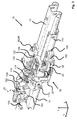
- the in Fig. 1 shown vehicle seat 1 for a motor vehicle has a seat part 3 and a relative to the seat part 3 in their inclination adjustable backrest 5.
- the inclination of the Backrest 5 may be adjustable, for example, by means of a detent fitting or a geared insert.
- the vehicle seat 1 is mounted on a longitudinal adjuster 10 for adjusting a seat longitudinal position.
- the in Fig. 2 shown longitudinal adjuster 10 of the vehicle seat 1 has two seat rail pairs, which are each formed of a first seat rail 12, in particular a seat-fixed upper rail, and a second seat rail 14, in particular a vehicle-fixed lower rail.
- the seat rails, each seat rail pair embrace each other and are movable in the longitudinal direction x relative to each other.
- the first seat rail 12 and the second seat rail 14 of the respective pair of seat rails, by means of a rail lock 18 are locked together, for the joint operation of the two rail locks 18, an actuator 16 is provided with a two rail locks 18 wirkverbindenden transmission rod 16 a, wherein the transmission rod 16 a with two rail locks 18 cooperates.
- the actuator 16 further includes a handle 16b engaging the transmission rod 16a.
- the longitudinal adjuster 10 has a memory device 20.
- the in Fig. 2 shown longitudinal adjuster 10 is in a ground state.
- the basic state of the illustrated longitudinal adjuster 10 describes that state when the vehicle seat 1 has assumed a seat longitudinal position preset by the occupant and the backrest 5 of the vehicle seat 1 is erected, and the vehicle seat 1 is accordingly in a position of use suitable for passenger transport.
- the term "ground state" of the vehicle seat 1 or the longitudinal adjuster 10 is generally understood that the ground state of the corresponding referenced components - unless explicitly defined otherwise - always corresponds to a state when the vehicle seat 1 is in a position of use and the memory Device 20, in particular a transmission 42 of the memory device 20, is in a state corresponding to the memory position. If reference is made here only to a single component, can also be spoken by a basic position.
- the memory position corresponds to a previously set and stored Seat longitudinal position, which can be left by a longitudinal displacement of the vehicle seat 1 and then taken again.
- the memory device 20 detects a resulting from a longitudinal displacement of the vehicle seat 1 relative movement between the first seat rail 12 and the second seat rail 14 by means of a friction wheel 22 and a gear 42.
- a acting between the first seat rail 12 and the second seat rail 14 rail lock 18 is by means an actuating lever 16c unlocked, wherein a folding forward of the backrest 5 of the vehicle seat 1 acts at least indirectly on the actuating lever 16c to unlock the rail lock 18.
- One of the longitudinal adjuster 10 basically provided function for adjusting the seat longitudinal position of the vehicle seat 1 by means of a handle 16b, which is arranged as shown on a transmission rod 16a, operable.
- the actuating lever 16 c is arranged on the transmission rod 16 a, which is adapted to act on a not shown rail locking 18 of the rail pair, in particular both rail pairs, the Leksseinstellers 10 to unlock this and the vehicle seat 1 according to the x parallel to the longitudinal direction x and / or to be able to move.
- the actuating lever 16c is connected, for example, by means of a welded connection to the transmission rod 6 and together with the latter is rotatably mounted on the first seat rail 12 via a common axis of rotation.
- the operating lever 16c may further be formed integrally with the handle 16b.
- the transmission rod 16a essentially serves the simultaneous actuation and unlocking of the rail lock 18 of a first seat rail pair and a rail lock 18 of a seat rail pair likewise formed from a further first seat rail 12 and a further second seat rail 14 of the longitudinal adjuster 10, which is provided on an opposite side of the vehicle seat 1 can be.
- the memory device 20 is adapted to serve an easy-entry function and upon actuation of the same by means of the transmission 42 a longitudinal displacement, or a relative movement of the first seat rail 12 relative to the second seat rail 14 to detect in terms of length and in the case of repeated use the memory position to block a further longitudinal displacement, in particular by blocking the friction wheel 22 to prevent.
- the transmission 42 is preferably covered with a transmission housing, in particular a first housing part 78 and a second housing part 80, which in Fig. 4 is shown.
- the memory position corresponds to the "stored seat longitudinal position", which may also be referred to as such, and is subsequently used as a synonym.
- Fig. 3 shows an enlarged view of the pair of seat rails with the memory device 20, wherein the memory device 20 of the first seat tickets 12 is assigned and cooperates with the second seat rail 14.
- the memory device 20 is preferably fixedly connected to the first seat rail 12, in the present case by means of preferably attached to the first seat rail 12 threaded bolts 88 and nuts 90 mounted.
- a relative movement between the first seat rail 12 and the second seat rail 14 that originates from a seat longitudinal position designated as a memory position can be detected.
- the friction wheel 22 is rotatably mounted in a Reibradschwinge 32.
- the longitudinal adjuster 10 also has a pulley 120, which serves to receive an end of a Bowden cable, not shown.
- a second end of the Bowden cable is preferably connected to the backrest 5, so that the pulley 120 is rotated about the axis of rotation of the pulley 120 when the backrest 5 is folded forward.
- the pulley 120 has an axially extending cam 122 which acts on a free end of the operating lever 16c when the pulley 120 is rotated.
- the memory device 20 also has a housing formed from the first housing part 78 and the second housing part 80.
- the memory device 20 has an adapter 102 on an end-side end section of the friction-wheel rocker 32.
- the adapter 102 holds a brake element 100.
- the brake element 100 extends in the present case substantially over the entire extent of the Reibradschwinge 32 in the vertical direction z. Consequently, the brake element 100 is presently wider than the friction wheel 22.
- the brake element 100 may be made of a plastic, in particular of an elastomer.
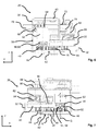
- FIGS. 4 to 7 show the memory device 20 from different angles.
- first and a second support member 38, 40 which are interconnected, in particular vernietbar, are.
- the first and second carrier part 38, 40 are preferably made of a metallic material, in particular a metal sheet.
- the first and second carrier part 38, 40 are screwed by means of a respective threaded bolt 88 and a nut 90 with the first seat rail 12.
- a spacer 86 is provided between the support members 38, 40 and the first seat rail 12, which may be configured differently thick and an adjustment of the position of the friction wheel 22 on the second seat rail 14 due to differently ausgestalteter rail profiles.
- the friction wheel 22 has a rim 24, which is completely enclosed by a friction lining 26.
- the friction wheel 22 is held by means of a bearing pin 30 in the Reibradschwinge 32 and rotatably mounted about a Reibradachse R.
- the Reibradschwinge 32 is pivotally mounted about a swing axis S.
- the friction wheel axis R and the swing arm axis S run parallel to a vertical direction z.
- the friction wheel 22 drives during the relative movement of the transmission 42 of the memory device 20 at.
- first a first gear 44 of the transmission 42 is rotatably mounted about the Reibradachse R and rotatably connected to the friction wheel 22.
- a rotational movement of the friction wheel 22 is thus transferable by means of the first gear 44 to an adjacent arranged and with the first gear 44 in engagement second gear 46.
- the second gear 46 is preferably rotatably mounted about the swing arm axis S.
- the second gear 46 is held together with a lower arm of the Reibradschwinge 32 by means of a first pin 34 in the first support member 38.
- An upper arm of the Reibradschwinge 32 is supported by a second pin 36 in the second support member 40.
- a third gear 48 of the gear 42 is rotatably mounted about a bearing pin 68 of a spindle-nut assembly 50 and also rotatably connected to a threaded spindle 52 of the spindle-nut assembly 50.
- the gears 44, 46, 48 of the transmission 42 are pairwise dimensioned according to predetermined reduction ratios and / or gear ratios.
- the threaded spindle 52 is rotatably supported by means of the bearing pin 68 about a spindle axis G.
- the spindle-nut assembly 50 acts by means of a non-rotatably mounted on a bearing portion 62 of the spindle-nut assembly 50 toothed segment 66 on a rack 70.
- the rack 70 is slidably held in a formed in the second housing part 80 guide.
- the guide has an opening for the passage for the toothed segment 66.
- the longitudinal x outer edges of the opening serve each as an end stop for the toothed segment 66th
- a control contour 74 which acts on a locking pin 82.
- the locking pin 82 can be brought into engagement with a recess 28 in the rim 24 of the friction wheel 22.
- the locking pin 82 is biased by means of a spring element 84 in the direction of a release position in which the locking pin 82 is out of engagement with the recess 28 of the rim 24, biased.
- the locking pin 82 In the in the FIGS. 4 to 7 illustrated state of the memory device 20 is the locking pin 82 in the blocking position, in which the locking pin 82 is in engagement with the recess 28 when the vehicle seat 1 is in the memory position.
- the Rack 70 is preferably biased by a spring element 72 in the direction of cooperating with the release position of the locking pin 82 position of the rack 70 resiliently.
- a co-operating with the spindle-nut assembly 50 stop 54 is provided, which is in the memory position in abutment with a stop 58 of a mounted on an external thread of the threaded spindle 52 nut 56.
- the stop 54 is presently formed on a portion of the threaded spindle 52.
- the stop 54 may be formed, for example, as part of the end face of the threaded spindle 52 arranged third gear 48.
- the nut 56 is screwed via an internal thread on the external thread of the threaded spindle 52 in the axial direction up and down. Further, the nut 56 on the outside of a coaxial with the spindle axis G of the threaded spindle 52 oriented longitudinal teeth 60.
- This longitudinal toothing 60 of the nut 56 is guided in a correspondingly also coaxial with the spindle axis G of the threaded spindle 52 oriented, designed as internal toothing, spline 64 of the bearing portion 62 in accordance with this coaxial direction parallel to the vertical direction z.
- the Fig. 8 essentially serves to reproduce the location of the cutting line of the Fig. 9 shown sectional view.
- a further illustration of the locking pin 82 is shown in the blocking position.
- the recess 28 designed in the form of a recess 28 extends in the rim 24 in the vertical direction z only over a part of the thickness of the rim 24.
- the locking pin 82 is guided in a bearing bush 92, whereby a penetration depth of the locking pin 82 is further limited .
- abrasion of the locking pin 82 is avoided at a bottom of the recess 28.
- the recess 28 may be completely formed passing through the rim 24.
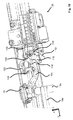
- FIGS. 10 to 13 show different views of the seat rail pair according to different angles Fig. 3 in the ground state.
- the Reibradschwinge 32 is spring-loaded by means of a leg spring 128 with a generation of a pressing force between the friction wheel 22 and the contact surface 14 a in the direction of the contact surface 14 a of the second seat rail 14.
- the memory device 20 can be set up to act on the friction wheel 22 with a comparatively lower pressure force, which merely undesirably lifts the friction wheel 22 away from the contact surface Prevents 14a and a secure detection of the relative movement of the first seat rail 12 relative to the second seat rail 14 allows.
- This serves to protect an unintentional lifting of the friction wheel 22 from the contact surface 14a, whereby rattling noises can occur.
- An intentional lifting of the friction wheel 22 of the contact surface 14 a can also be done by means of a reset mechanism, wherein the memory device 20 by means of a For example, acting on the gear 42 return spring is reset to a memory position corresponding zero value.
- a reset can be carried out, for example, when manually setting a new seat longitudinal position.
- the backrest 5 is presently operatively connected by means of a Bowden cable with the longitudinal adjuster 10.
- the Bowden cable is known to have a Bowden cable end, which is held on a pulley 120.
- the pulley 120 is rotatably mounted about a rotation axis.
- the pulley 120 has the axially projecting cam 122, which acts upon rotation of the pulley 120 on the actuating lever 16c such that the actuating lever 16c is pivoted about the axis of rotation of the transmission rod 16a and thereby the rail lock 18 of the longitudinal adjuster 10 is unlocked.
- leg spring 128, the first control lever 114 and the reset lever 110 in the opposite direction of rotation about the common axis A spring-loaded.
- the leg spring 128 is endeavored here to transfer the reset lever 110 into a non-contrasting the friction wheel 22 end position. Furthermore, the leg spring 128 drives the first control lever 114 in a forwardly inclined end position, which corresponds to the basic position.
- the memory device 20 has a reset lever 110 which is rotatably mounted about an axis A. At a downwardly projecting portion of the reset lever 110, a coupling 112 is arranged and operatively connected to the reset lever 110.
- the leg spring 128 causes the Reibradschwinge 32 is resiliently biased to generate the pressing force between the friction wheel 22 and the contact surface 14a in the direction of the contact surface 14a of the second seat rail 14.
- the first control lever 114 is pivotable relative to the reset lever 110 freely about the axis A, in particular, the first control lever 114 is not rotatably connected to the reset lever 110.
- a second control lever 116 is arranged at a distance from the axis A end of the first control lever 114.
- the second control lever 116 is pivotable about an axis B formed at the end of the first control lever 114.
- a control pin 118 is arranged at a spaced from the axis B end of the second control lever 116.
- the control pin 118 is perpendicular from the second control lever 116, in particular parallel to the transverse direction y, from.
- the control pin 118 is arranged in the region of a front upper edge of the reset lever 110 and at the same time in the pivoting range of the actuating lever 16c.
- the rail lock 18 can be unlocked manually and the first seat rail 12 can be displaced relative to the second seat rail 14 without detection of the relative movement in the longitudinal direction x.
- the changed seat longitudinal position then corresponds to a new stored seat longitudinal position.
- this is an example as follows.
- unlocking of the longitudinal adjuster 10 takes place, in particular unlocking or opening of the rail interlock 18, as a result of which the first seat rail 12 is released for relative movement to the second seat rail 14.
- the actuating lever 16c pivots about an axis of rotation of the transmission rod 16a and actuates the reset lever 110 via the control bolt 118.
- the reset lever 110 is rotated about the axis of rotation A during actuation by the actuating lever 16c and lifts the coupling mounted on the friction wheel rocker 32 Friction wheel 22 from the contact surface 14a of the second seat rail 14 from.
- the friction wheel 22 By the lifting off of the friction wheel 22 from the contact surface 14a, the friction wheel 22, or one of the memory device 20 stored seat longitudinal position or a detected relative movement, on a Zero value or defined output value reset.
- the memory device 20 has a restoring spring acting on the friction wheel 22, or preferably on the transmission 42, not shown in the figures.
- a slider 130 has at its rear end a receptacle 132 in the form of an eyelet, which serves for connection to a Bowden cable, not shown.
- This Bowden cable is preferably used to actuate an additional locking of a Lehneneinstellers, in particular for locking and locking the backrest 5 in a folded-forward position.
- the slider 130 is brought in the illustrated basic state at its rear end by a stop 136 of the rack 70 in abutment. In this basic state, the stopper 136 holds the slider 130 against a parallel to the longitudinal direction x backward spring force, which is initiated by the Bowden cable.
- This basic state of the slider 130 corresponds to a front end position of the slider 130.
- Fig. 13 shows in the sectional view that the cable pulley 120 has a radially formed projection 124 which is operatively connected to a control 126 aligned with the axis B. If the pulley 120 is rotated about its axis of rotation, the projection 124 pushes the control member 126 to the rear and thereby pivots the first control lever 114, which in this case takes along the second control lever 116. This condition is described below on the basis of FIGS. 14 to 16 described.
- FIGS. 14 to 16 the longitudinal adjuster 10 is shown in a state which can be brought about by folding in the backrest 5 of the vehicle seat 1.
- Fig. 16 shows an opposite side view of the memory device 20 of Fig. 14 , The illustrated state is taken, for example, when the vehicle seat 1 is transferred to a so-called easy-entry position.
- a transfer of the vehicle seat 1 in the easy-entry position is known to serve the creation of sufficient space for easier boarding in a rear row of seats of a motor vehicle.
- the pulley 120 is configured such that it pivots the first control lever 114 by means of the radially projecting projection 124 when the pulley 120 is rotated by folding the backrest 5.
- the pulley 120 acts by means of the projection 124 on the aligned with the axis B control element 126 when the pulley 120 is rotated about the axis of rotation.
- the projection 124 displaces the control member 126, as shown, to the rear, whereby the first control lever 114 is pivoted.
- the second control lever 116 follows the pivotal movement of the first control lever 114, the second control lever 116 also moves rearward in accordance with the movement of the axis B. At this time, the control pin 118 is pulled out of the swinging range of the operation lever 16c.
- the Bowden cable moves the cable pulley 120 about its axis of rotation.
- this first acts on the first control lever 114 by means of the radially projecting projection 124, whereby it is pivoted about the axis A.
- the second control lever 116 which is held on the first control lever 114, pivoted with, whereby the held on the second control lever 116 control pin 118 is moved out of a contact area in which it is contacted by the actuating lever 16c out.
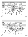
- Fig. 17 shows a top view of the memory device 20 in a state with folded backrest 5 after leaving the memory position.
- This Condition is taken when the vehicle seat 1, starting from the in Fig. 15 shown state is moved out of the memory position to the front.
- the friction wheel 22 detects in the manner described above, the relative movement between the first seat rail 12 and the second seat tickets 14.
- the rack 70 moves together with the stopper 136 to the rear, whereby the slider 130 by means of the force exerted by the Bowden cable spring force also displaced rearwardly and thereby locking a locking of the additional locking of Lehneneinstellers locked and the backrest 5 in the folded-forward position.
- Fig. 18 is a view from above of the memory device 20 in a state which can be brought about by raising the backrest 5 in a non-memory position corresponding longitudinal position of the vehicle seat 1. This may be necessary, for example, if the vehicle seat 1 from the easy-entry position is not completely pushed back into the memory position, for example, if this is prevented by behind the vehicle seat 1 befindliches cargo.
- the erection of the locked in the folded position backrest 5 can be carried out in a conventional manner by a manual actuation of the backrest adjuster. If the backrest 5 is therefore erected in a longitudinal position located in front of the memory position, the rail lock 18 is initially locked by a rotation of the cable pulley 120.
- first control lever 114 together with the second control lever 116 is replaced by the leg spring 128 pivoted about the axis A to the front.
- the pivoting of the first control lever 114 effected by the leg spring 128 acts on a front hook-shaped portion 134 of the slider 130, which is guided against the movement of the first control lever 114 into the front end position against the spring force exerted by the Bowden cable.
- the exercisable by means of the leg spring 128 on the slider 130 force is therefore greater than the means of the Bowden cable on the receptacle 132 attacking force.
- the receptacle 132 is spaced from the stop 136 of the rack 70.
Landscapes
- Engineering & Computer Science (AREA)
- Aviation & Aerospace Engineering (AREA)
- Transportation (AREA)
- Mechanical Engineering (AREA)
- Seats For Vehicles (AREA)
Priority Applications (1)
| Application Number | Priority Date | Filing Date | Title |
|---|---|---|---|
| EP16186147.1A EP3290261A1 (fr) | 2016-08-29 | 2016-08-29 | Dispositif de reglage en longueur de siege de vehicule et siege de vehicule |
Applications Claiming Priority (1)
| Application Number | Priority Date | Filing Date | Title |
|---|---|---|---|
| EP16186147.1A EP3290261A1 (fr) | 2016-08-29 | 2016-08-29 | Dispositif de reglage en longueur de siege de vehicule et siege de vehicule |
Publications (1)
| Publication Number | Publication Date |
|---|---|
| EP3290261A1 true EP3290261A1 (fr) | 2018-03-07 |
Family
ID=56842703
Family Applications (1)
| Application Number | Title | Priority Date | Filing Date |
|---|---|---|---|
| EP16186147.1A Withdrawn EP3290261A1 (fr) | 2016-08-29 | 2016-08-29 | Dispositif de reglage en longueur de siege de vehicule et siege de vehicule |
Country Status (1)
| Country | Link |
|---|---|
| EP (1) | EP3290261A1 (fr) |
Cited By (2)
| Publication number | Priority date | Publication date | Assignee | Title |
|---|---|---|---|---|
| CN113518732A (zh) * | 2019-03-04 | 2021-10-19 | 安道拓工程技术知识产权有限公司 | 用于机动化纵向调节车辆座椅的纵向调节装置及车辆座椅 |
| US11332044B2 (en) | 2018-05-25 | 2022-05-17 | Magna Seating Inc | Manual pitch easy-entry seat with power return |
Citations (3)
| Publication number | Priority date | Publication date | Assignee | Title |
|---|---|---|---|---|
| DE19509344A1 (de) * | 1995-03-15 | 1996-09-19 | Keiper Recaro Gmbh Co | Fahrzeugsitz |
| DE10202179A1 (de) | 2002-01-22 | 2003-08-07 | Keiper Gmbh & Co Kg | Längseinsteller für einen Fahrzeugsitz |
| WO2004089683A1 (fr) * | 2003-04-10 | 2004-10-21 | Johnson Controls Automotive (Uk) Ltd | Ensemble de siege de vehicule |
-
2016
- 2016-08-29 EP EP16186147.1A patent/EP3290261A1/fr not_active Withdrawn
Patent Citations (3)
| Publication number | Priority date | Publication date | Assignee | Title |
|---|---|---|---|---|
| DE19509344A1 (de) * | 1995-03-15 | 1996-09-19 | Keiper Recaro Gmbh Co | Fahrzeugsitz |
| DE10202179A1 (de) | 2002-01-22 | 2003-08-07 | Keiper Gmbh & Co Kg | Längseinsteller für einen Fahrzeugsitz |
| WO2004089683A1 (fr) * | 2003-04-10 | 2004-10-21 | Johnson Controls Automotive (Uk) Ltd | Ensemble de siege de vehicule |
Cited By (4)
| Publication number | Priority date | Publication date | Assignee | Title |
|---|---|---|---|---|
| US11332044B2 (en) | 2018-05-25 | 2022-05-17 | Magna Seating Inc | Manual pitch easy-entry seat with power return |
| CN113518732A (zh) * | 2019-03-04 | 2021-10-19 | 安道拓工程技术知识产权有限公司 | 用于机动化纵向调节车辆座椅的纵向调节装置及车辆座椅 |
| CN113518732B (zh) * | 2019-03-04 | 2023-09-05 | 安道拓美国有限责任公司 | 用于机动化纵向调节车辆座椅的纵向调节装置及车辆座椅 |
| US11833933B2 (en) | 2019-03-04 | 2023-12-05 | Adient Us Llc | Longitudinal adjusting device for the motorized longitudinal adjustment of a vehicle seat, and vehicle seat |
Similar Documents
| Publication | Publication Date | Title |
|---|---|---|
| EP1474308B3 (fr) | Dispositif de reglage en longueur d'un siege de vehicule | |
| EP3325310B1 (fr) | Siège de véhicule | |
| DE102009029858A1 (de) | Baugruppe mit Rastbeschlag und Freischwenkmechanik | |
| DE102008061037B3 (de) | Fahrzeugsitz mit Klinkenanordnung | |
| EP1337417B1 (fr) | Siege de vehicule automobile | |
| EP3162620B1 (fr) | Dispositif de réglage longitudinal d'un siège de véhicule, siège de véhicule | |
| DE10201534B4 (de) | Fahrzeugsitzverschiebevorrichtung | |
| DE69700556T2 (de) | Nach vorn bewegbarer Fahrzeugsitz, um zu einem hinteren Raum zu gelangen | |
| EP2254767B1 (fr) | Siege de vehicule a moteur pouvant etre prealablement deplace, comprenant une garniture d'articulation de dossier et garniture d'articulation de dossier | |
| WO2006058646A2 (fr) | Dispositif de reglage longitudinal pour un siege de vehicule | |
| EP3162619B1 (fr) | Dispositif de réglage longitudinal d'un siège de véhicule, siège de véhicule | |
| EP3280610B1 (fr) | Dispositif pour siège de véhicule et siège de véhicule | |
| EP3290261A1 (fr) | Dispositif de reglage en longueur de siege de vehicule et siege de vehicule | |
| DE102009010226A1 (de) | Kraftfahrzeugsitz | |
| DE102016210905B4 (de) | Längseinsteller für einen Fahrzeugsitz und Fahrzeugsitz | |
| EP3162618B1 (fr) | Dispositif de réglage longitudinal d'un siège de véhicule, siège de véhicule | |
| EP3290260B1 (fr) | Dispositif de reglage en longueur de siege de vehicule et siege de vehicule | |
| EP3290259B1 (fr) | Dispositif de reglage en longueur de siege de vehicule et siege de vehicule | |
| EP3162617B1 (fr) | Dispositif de réglage longitudinal d'un siège de véhicule, siège de véhicule | |
| EP3162616A1 (fr) | Dispositif de réglage longitudinal d'un siège de véhicule, siège de véhicule | |
| DE102016210904B4 (de) | Längseinsteller für einen Fahrzeugsitz und Fahrzeugsitz | |
| DE102015221075B4 (de) | Längseinsteller für einen fahrzeugsitz, fahrzeugsitz | |
| EP3280614B1 (fr) | Dispositif de réglage en longueur d'un siège de véhicule et siège de véhicule | |
| EP3280613B1 (fr) | Dispositif de réglage en longueur, siège de véhicule | |
| EP3280612B1 (fr) | Dispositif mémoire pour siège de véhicule et siège de véhicule |
Legal Events
| Date | Code | Title | Description |
|---|---|---|---|
| PUAI | Public reference made under article 153(3) epc to a published international application that has entered the european phase |
Free format text: ORIGINAL CODE: 0009012 |
|
| AK | Designated contracting states |
Kind code of ref document: A1 Designated state(s): AL AT BE BG CH CY CZ DE DK EE ES FI FR GB GR HR HU IE IS IT LI LT LU LV MC MK MT NL NO PL PT RO RS SE SI SK SM TR |
|
| AX | Request for extension of the european patent |
Extension state: BA ME |
|
| RAP1 | Party data changed (applicant data changed or rights of an application transferred) |
Owner name: ADIENT LUXEMBOURG HOLDING S.A R.L. |
|
| STAA | Information on the status of an ep patent application or granted ep patent |
Free format text: STATUS: THE APPLICATION IS DEEMED TO BE WITHDRAWN |
|
| 18D | Application deemed to be withdrawn |
Effective date: 20180908 |