EP3290241A1 - Hybrid lower arm - Google Patents
Hybrid lower arm Download PDFInfo
- Publication number
- EP3290241A1 EP3290241A1 EP15890856.6A EP15890856A EP3290241A1 EP 3290241 A1 EP3290241 A1 EP 3290241A1 EP 15890856 A EP15890856 A EP 15890856A EP 3290241 A1 EP3290241 A1 EP 3290241A1
- Authority
- EP
- European Patent Office
- Prior art keywords
- lower arm
- end portions
- metal member
- face portion
- guard member
- Prior art date
- Legal status (The legal status is an assumption and is not a legal conclusion. Google has not performed a legal analysis and makes no representation as to the accuracy of the status listed.)
- Withdrawn
Links
- 229910052751 metal Inorganic materials 0.000 claims abstract description 34
- 239000002184 metal Substances 0.000 claims abstract description 34
- 239000000463 material Substances 0.000 claims abstract description 14
- 238000005192 partition Methods 0.000 claims description 10
- 239000004033 plastic Substances 0.000 claims description 5
- 229920003023 plastic Polymers 0.000 claims description 5
- 230000008878 coupling Effects 0.000 description 8
- 238000010168 coupling process Methods 0.000 description 8
- 238000005859 coupling reaction Methods 0.000 description 8
- 239000000725 suspension Substances 0.000 description 5
- 239000000470 constituent Substances 0.000 description 4
- 230000007797 corrosion Effects 0.000 description 3
- 238000005260 corrosion Methods 0.000 description 3
- 238000005516 engineering process Methods 0.000 description 3
- 229910000831 Steel Inorganic materials 0.000 description 2
- 239000006096 absorbing agent Substances 0.000 description 2
- 229910052782 aluminium Inorganic materials 0.000 description 2
- XAGFODPZIPBFFR-UHFFFAOYSA-N aluminium Chemical compound [Al] XAGFODPZIPBFFR-UHFFFAOYSA-N 0.000 description 2
- 238000013016 damping Methods 0.000 description 2
- 239000011152 fibreglass Substances 0.000 description 2
- 230000035939 shock Effects 0.000 description 2
- 239000010959 steel Substances 0.000 description 2
- 241000219122 Cucurbita Species 0.000 description 1
- 235000009852 Cucurbita pepo Nutrition 0.000 description 1
- 230000032683 aging Effects 0.000 description 1
- 230000005540 biological transmission Effects 0.000 description 1
- 238000005336 cracking Methods 0.000 description 1
- 230000000694 effects Effects 0.000 description 1
- 238000001746 injection moulding Methods 0.000 description 1
- 238000004519 manufacturing process Methods 0.000 description 1
- 239000007769 metal material Substances 0.000 description 1
- 230000001737 promoting effect Effects 0.000 description 1
- 238000005096 rolling process Methods 0.000 description 1
- 239000003381 stabilizer Substances 0.000 description 1
Images


Classifications
-
- B—PERFORMING OPERATIONS; TRANSPORTING
- B60—VEHICLES IN GENERAL
- B60G—VEHICLE SUSPENSION ARRANGEMENTS
- B60G7/00—Pivoted suspension arms; Accessories thereof
- B60G7/001—Suspension arms, e.g. constructional features
-
- B—PERFORMING OPERATIONS; TRANSPORTING
- B60—VEHICLES IN GENERAL
- B60G—VEHICLE SUSPENSION ARRANGEMENTS
- B60G7/00—Pivoted suspension arms; Accessories thereof
-
- B—PERFORMING OPERATIONS; TRANSPORTING
- B60—VEHICLES IN GENERAL
- B60G—VEHICLE SUSPENSION ARRANGEMENTS
- B60G7/00—Pivoted suspension arms; Accessories thereof
- B60G7/005—Ball joints
-
- B—PERFORMING OPERATIONS; TRANSPORTING
- B60—VEHICLES IN GENERAL
- B60G—VEHICLE SUSPENSION ARRANGEMENTS
- B60G7/00—Pivoted suspension arms; Accessories thereof
- B60G7/02—Attaching arms to sprung part of vehicle
-
- B—PERFORMING OPERATIONS; TRANSPORTING
- B60—VEHICLES IN GENERAL
- B60G—VEHICLE SUSPENSION ARRANGEMENTS
- B60G7/00—Pivoted suspension arms; Accessories thereof
- B60G7/04—Buffer means for limiting movement of arms
-
- F—MECHANICAL ENGINEERING; LIGHTING; HEATING; WEAPONS; BLASTING
- F16—ENGINEERING ELEMENTS AND UNITS; GENERAL MEASURES FOR PRODUCING AND MAINTAINING EFFECTIVE FUNCTIONING OF MACHINES OR INSTALLATIONS; THERMAL INSULATION IN GENERAL
- F16D—COUPLINGS FOR TRANSMITTING ROTATION; CLUTCHES; BRAKES
- F16D3/00—Yielding couplings, i.e. with means permitting movement between the connected parts during the drive
- F16D3/16—Universal joints in which flexibility is produced by means of pivots or sliding or rolling connecting parts
- F16D3/20—Universal joints in which flexibility is produced by means of pivots or sliding or rolling connecting parts one coupling part entering a sleeve of the other coupling part and connected thereto by sliding or rolling members
- F16D3/22—Universal joints in which flexibility is produced by means of pivots or sliding or rolling connecting parts one coupling part entering a sleeve of the other coupling part and connected thereto by sliding or rolling members the rolling members being balls, rollers, or the like, guided in grooves or sockets in both coupling parts
-
- B—PERFORMING OPERATIONS; TRANSPORTING
- B60—VEHICLES IN GENERAL
- B60G—VEHICLE SUSPENSION ARRANGEMENTS
- B60G2200/00—Indexing codes relating to suspension types
- B60G2200/10—Independent suspensions
- B60G2200/14—Independent suspensions with lateral arms
- B60G2200/154—Independent suspensions with lateral arms the lateral arm having an L-shape
-
- B—PERFORMING OPERATIONS; TRANSPORTING
- B60—VEHICLES IN GENERAL
- B60G—VEHICLE SUSPENSION ARRANGEMENTS
- B60G2204/00—Indexing codes related to suspensions per se or to auxiliary parts
- B60G2204/10—Mounting of suspension elements
- B60G2204/14—Mounting of suspension arms
- B60G2204/143—Mounting of suspension arms on the vehicle body or chassis
- B60G2204/1431—Mounting of suspension arms on the vehicle body or chassis of an L-shaped arm
-
- B—PERFORMING OPERATIONS; TRANSPORTING
- B60—VEHICLES IN GENERAL
- B60G—VEHICLE SUSPENSION ARRANGEMENTS
- B60G2204/00—Indexing codes related to suspensions per se or to auxiliary parts
- B60G2204/40—Auxiliary suspension parts; Adjustment of suspensions
- B60G2204/41—Elastic mounts, e.g. bushings
-
- B—PERFORMING OPERATIONS; TRANSPORTING
- B60—VEHICLES IN GENERAL
- B60G—VEHICLE SUSPENSION ARRANGEMENTS
- B60G2204/00—Indexing codes related to suspensions per se or to auxiliary parts
- B60G2204/40—Auxiliary suspension parts; Adjustment of suspensions
- B60G2204/416—Ball or spherical joints
-
- B—PERFORMING OPERATIONS; TRANSPORTING
- B60—VEHICLES IN GENERAL
- B60G—VEHICLE SUSPENSION ARRANGEMENTS
- B60G2206/00—Indexing codes related to the manufacturing of suspensions: constructional features, the materials used, procedures or tools
- B60G2206/01—Constructional features of suspension elements, e.g. arms, dampers, springs
- B60G2206/014—Constructional features of suspension elements, e.g. arms, dampers, springs with reinforcing nerves or branches
-
- B—PERFORMING OPERATIONS; TRANSPORTING
- B60—VEHICLES IN GENERAL
- B60G—VEHICLE SUSPENSION ARRANGEMENTS
- B60G2206/00—Indexing codes related to the manufacturing of suspensions: constructional features, the materials used, procedures or tools
- B60G2206/01—Constructional features of suspension elements, e.g. arms, dampers, springs
- B60G2206/10—Constructional features of arms
- B60G2206/12—Constructional features of arms with two attachment points on the sprung part of the vehicle
-
- B—PERFORMING OPERATIONS; TRANSPORTING
- B60—VEHICLES IN GENERAL
- B60G—VEHICLE SUSPENSION ARRANGEMENTS
- B60G2206/00—Indexing codes related to the manufacturing of suspensions: constructional features, the materials used, procedures or tools
- B60G2206/01—Constructional features of suspension elements, e.g. arms, dampers, springs
- B60G2206/10—Constructional features of arms
- B60G2206/122—Constructional features of arms the arm having L-shape
-
- B—PERFORMING OPERATIONS; TRANSPORTING
- B60—VEHICLES IN GENERAL
- B60G—VEHICLE SUSPENSION ARRANGEMENTS
- B60G2206/00—Indexing codes related to the manufacturing of suspensions: constructional features, the materials used, procedures or tools
- B60G2206/01—Constructional features of suspension elements, e.g. arms, dampers, springs
- B60G2206/10—Constructional features of arms
- B60G2206/14—Constructional features of arms the arm forming a U-shaped recess for fitting a bush
-
- B—PERFORMING OPERATIONS; TRANSPORTING
- B60—VEHICLES IN GENERAL
- B60G—VEHICLE SUSPENSION ARRANGEMENTS
- B60G2206/00—Indexing codes related to the manufacturing of suspensions: constructional features, the materials used, procedures or tools
- B60G2206/01—Constructional features of suspension elements, e.g. arms, dampers, springs
- B60G2206/10—Constructional features of arms
- B60G2206/16—Constructional features of arms the arm having a U profile and/or made of a plate
-
- B—PERFORMING OPERATIONS; TRANSPORTING
- B60—VEHICLES IN GENERAL
- B60G—VEHICLE SUSPENSION ARRANGEMENTS
- B60G2206/00—Indexing codes related to the manufacturing of suspensions: constructional features, the materials used, procedures or tools
- B60G2206/01—Constructional features of suspension elements, e.g. arms, dampers, springs
- B60G2206/70—Materials used in suspensions
- B60G2206/71—Light weight materials
- B60G2206/7104—Thermoplastics
-
- B—PERFORMING OPERATIONS; TRANSPORTING
- B60—VEHICLES IN GENERAL
- B60G—VEHICLE SUSPENSION ARRANGEMENTS
- B60G2206/00—Indexing codes related to the manufacturing of suspensions: constructional features, the materials used, procedures or tools
- B60G2206/01—Constructional features of suspension elements, e.g. arms, dampers, springs
- B60G2206/70—Materials used in suspensions
- B60G2206/72—Steel
Definitions
- the present disclosure relates to a hybrid lower arm and, more particularly, to a hybrid lower arm having a guard member at one surface thereof to prevent painted surfaces from being damaged due to chipping while a vehicle is being driven.
- a vehicular suspension system is generally referred to as a suspension, and is an apparatus for connecting a wheel to a vehicular body.
- the vehicular suspension system consists of a spring that adjusts transmission of an impact from a road surface to the vehicular body, a shock absorber that absorbs the impact from the road surface together with the spring, an arm or a link that controls an operation of the wheel, and a stabilizer that prevents rolling of the vehicle.
- the aforementioned vehicular suspension system is an important apparatus for promoting ride comfort and driving stability, and mainly performs the functions of suppressing or rapidly reducing vibrations transmitted from the vehicular wheel while supporting the vehicular body from the vehicular wheel in a stable manner.
- a lower arm 40 is used to perform the functions of connecting a vehicular wheel to a vehicular body and supporting the vehicular wheel. As shown in FIG. 8 , such a lower arm 40 is provided with a damping joint 2, a vehicular body mounting bush 3, and a ball joint 1 at respective end portions thereof, to thereby mount the vehicular wheel to the vehicular body.
- the lower arm 40 includes three end portions.
- One end portion of the three end portions is coupled to a knuckle of the vehicular wheel via the ball joint 1 and supports the vehicular wheel together with an upper arm.
- the other end portions of the three end portions are coupled to a frame 10 of the vehicular body via the damping joint 2 and the vehicular body mounting bush 3.
- FIG. 9 is a front perspective view of a lower arm according to a prior art technology
- FIG. 10 is a sectional view of part B in FIG. 9
- the lower arm 40 of prior art consists of a main member 41 made of a metal material, and a covering member 42 mounted on one surface of the main member 41.
- the main member 41 largely consists of a base portion 41 a, a connection portion 41 b, and a plurality of pin portions 41 c.
- the covering member 42 is coupled to upper and lower surfaces of the connection portion 41 b and the pin portions 41 c.
- the lower arm 40 of prior art is configured such that separate covering members are not provided at an outer surface and upper and lower surfaces of the base portion 41 a.
- corrosion or aging occurs in the lower arm 40 when painted surfaces are damaged due to chipping which occurs while the vehicle is being driven.
- the present disclosure has been devised to solve the aforementioned problems, and the object of the present disclosure is to provide a hybrid lower arm which includes a guard member at one face portion of the lower arm so as to prevent damage of painted surfaces.
- a hybrid lower arm may include a metal member, a face portion, and a guard member.
- the metal member may include a plurality of end portions. One end portion of the plurality of end portions may be connected to a ball joint and another end portion of the plurality of end portions may be connected to a vehicular body.
- the face portion may be formed so as to extend downwards along an edge of the metal member between the one end portion and the another end portion.
- the guard member may be configured to surround a portion of the face portion, and may be formed of a material lighter than the metal member.
- a lower end of the face portion may be bent toward an inner side of the metal member.
- the guard member may be formed of a plastic material, and may be configured to surround an inward surface, an outward surface and a lower end surface of the face portion.
- the metal member may include a body portion formed in a shape of an L-shaped plate.
- the guard member may be formed so as to surround a lower surface of the body portion, an inward surface of the face portion and an outward surface of the face portion.
- the guard member may be formed with a plurality of partition walls which extend downwards from the lower surface of the body portion to support the face portion and are connected to the face portion.
- the metal member may be formed with three end portions.
- a ball joint hole may be formed at one end portion of the three end portions, a first bush connection hole may be formed at another end portion of the three end portions, a second bush connection portion may be formed at the other end portion of the three end portions, and a center hole may be formed among the three end portions.
- the guard member may be formed of a plastic material and is formed to surround an outward surface of the face portion formed in a vertical direction between the ball joint hole and the first bush connection portion, and to surround a bent portion of the body portion.
- the hybrid lower arm is configured with the guard member, it is possible to prevent painted surfaces from being damaged due to chipping. Therefore, it is possible to prevent corrosion or damage occurring in the hybrid lower arm and improve durability of the hybrid lower arm.
- FIG. 1 is a front perspective view of a hybrid lower arm according to an embodiment of the present disclosure.
- FIG. 2 is a sectional view of part A in FIG. 1 .
- FIG. 3 is a partially cut-away perspective view of a hybrid lower arm according to an embodiment of the present disclosure.
- FIG. 4 is a perspective view showing a metal member of a hybrid lower arm according to an embodiment of the present disclosure.
- FIG. 5 is a perspective view showing a guard member of a hybrid lower arm according to an embodiment of the present disclosure.
- FIG. 6 is a rear perspective view of a hybrid lower arm according to an embodiment of the present disclosure.
- a left side in a drawing is referred to as “one side,” “one end,” “one end portion” or a name similar thereto
- a right side in a drawing is referred to as an "opposite side,” an "opposite end,” an “opposite end portion,” or a name similar thereto.
- a hybrid lower arm 100 is formed in an approximately L-like shape, and includes a metal member 110 and a guard member 120.
- the metal member 110 is formed of a steel or aluminum material, and includes a body portion 111 and a face portion 131.
- the body portion 111 is formed in an approximately plate shape, and edges of the body portion 111 are bent in a vertical direction of the drawing.
- the body portion 111 may be formed with three end portions.
- a ball joint hole 112 is formed at one end portion of the three end portions
- a first bush connection hole 113 is formed at another end portion of the three end portions
- a second bush connection portion 114 is formed at the other end portion of the three end portions.
- a center hole 115 is formed at a center of the body portion 111 among the three end portions.
- a first bent portion 1161 is formed at the edge of the body portion 111.
- the face portion 131 extends along the first bent portion 1161 toward a lower side of the drawing.
- the body portion 111 is formed with the ball joint hole 112, the first bush connection hole 113, the second bush connection portion 114, and the center hole 115.
- the ball joint hole 112 is formed so as to perforate in the vertical direction at the one end portion of the body portion 111.
- a ball joint 1121 may be fixedly provided at the ball joint hole 112 and may connect with a vehicular wheel.
- the first bush connection hole 113 is formed so as to perforate in the vertical direction at the another end portion of the body portion 111.
- a first bush 1131 is provided at the first bush connection hole 113.
- the first bush 1131 is coupled to a vehicular body.
- the second bush connection portion 114 protrudes from a side surface of the other end portion of the body portion 111.
- the second bush connection portion 114 has a hollow cylindrical shape, and a second bush 1141 is provided at an inner side of the second bush connection portion.
- the center hole 115 is formed among the ball joint hole 112, the first bush connection hole 113, and the second bush connection portion 114.
- the center hole 115 is formed to perforate in the vertical direction.
- a shock absorber is connected through the center hole 115.
- the face portion 131 is formed so as to be bent in the vertical direction at the edge of the body portion 111.
- the face portion 131 includes a first face portion 116, a second face portion 117, and a third face portion 118.
- the first, second, and third face portions 116, 117, and 118 may be formed as a single integral portion and may constitute a side surface of the body portion 111.
- a downward direction of the body portion 111 and a direction toward a portion surrounded by the first, second, and third face portions 116, 117, and 118 are referred to as “inward,” while a direction opposite to the inward direction is referred to as “outward.”
- the first face portion 116 is formed so as to extend from the edge of the body portion 111 toward the lower side of the drawing between the ball joint hole 112 and the second bush connection portion 114.
- a second bent portion 1163 is bent inward at a lower end of the first face portion 116.
- the second face portion 117 extends downwards from the edge of the body portion 111 between the ball joint hole 112 and the first bush connection hole 113.
- the second face portion 117 is formed to bend arcuately.
- the second bent portion 1163 is bent inward at a lower end of the second face portion 117.
- the third face portion 118 is formed so as to extend downwards from the edge of the body portion 111 between the first bush connection hole 113 and the second bush connection portion 114.
- An inward surface of the second face portion 117 is configured to face respective inward surfaces of the first face portion 116 and the third face portion 118.
- the guard member 120 is formed of a plastic material by insert injection molding together with the metal member 110.
- the guard member 120 may be formed of Glass Fiber Reinforced Plastic (GFRP).
- the guard member 120 is configured to surround the first face portion 116 of the metal member 110. That is, the guard member 120 may be configured to surround the first bent portion 1161, the first face portion 116, and the second bent portion 1163. Since the second bent portion 1163 is bent inward as described above, the guard member 120 is more firmly coupled to the metal member 110.
- the guard member 120 surrounding the first bent portion 1161 is configured such that a height of the guard member 120 is aligned with an outer surface of the body portion 111 in the vertical direction.
- the guard member 120 is configured to cover the inner surface and the outer surface of the first bent portion 1161, but does not extend to an upper surface and an outer surface of the body portion 111. Accordingly, when compared with a guard member covering the entire surface of the body portion 111, the guard member 120 can reduce the production cost or weight. Further, since the guard member 120 extends up to the bent portion, the guard member 120 is firmly mounted to the metal member 110 and demounting of the guard member is not easily facilitated.
- the guard member 120 may be provided not only at the first face portion 116, but also at the inner side of the metal member 110.
- the guard member 120 may be configured in a shape of surround the face portion 131 of the metal member 110 and the inner surface of the body portion 111. That is, the guard member 120 may be provided so as to surround all of the inward surfaces, the lower surfaces, and the outward surfaces of the face portions 116, 117, and 118.
- a partition wall 121 which extends in the vertical direction in the same direction as the extension direction of the face portion 131, may be provided at an inner side of the guard member 120. Both sides of the partition wall 121 are coupled to the inward surface of the face portion 131. For example, where one side of the partition wall 121 is coupled to the first face portion 116, the opposite side of the partition wall 121 is coupled to the second face portion 117 or the third face portion 118.
- the partition wall 121 may be formed of a plurality of partition walls, and the respective partition walls 121 may be configured to intersect with each other.
- the face portion 131 can be prevented from being damaged by an external impact.
- the first face portion 116 of the guard member 110 can be prevented from cracking or being damaged.
- the guard member 120 is formed of a material different from the metal member 110.
- a volume ratio of the metal member 110 is set in a range of 10% or more and less than 99%.
- the hybrid lower arm 100 since the metal member 110 and the guard member 120 are formed of different materials, the hybrid lower arm 100 according to an embodiment of the present disclosure has an effect of reduced weight when compared with a case where the metal member and the guard member are made of a single material. Further, since the lower end of the face portion 131 of the metal member 110 is bent inward, the metal member 110 and the guard member 120 can be prevented from being separated from each other.
- FIG. 7 is a top view of a hybrid lower arm provided at a rear wheel according to another embodiment.
- a transverse direction of the drawing is referred to as a "length direction”
- a longitudinal direction of the drawing is referred to as a “width direction”
- a direction perpendicular to the paper surface of the drawing is referred to as a "vertical direction.”
- a hybrid lower arm 200 is provided at a rear wheel of a vehicle, and includes a body portion 210, a first coupling portion 220, and a second coupling portion 230.
- the body portion 210 may be formed of a steel or aluminum material.
- the body portion 210 is formed in a shape of a plate extending in the length direction.
- the body portion 210 is formed in a shape of a gourd bottle. Similar to the above-described first embodiment, edges of the body portion 210 are formed to bend in the vertical direction.
- a spring seat hole which is opened in the vertical direction, is formed at a center of the body portion 210, and a hollow cylindrical spring seat 212 is mounted at an inner side of the spring seat hole.
- first coupling portion 220 and the second coupling portion 230 are formed at two ends of the body portion 210 in the length direction.
- the first coupling portion 220 is formed to extend from one side of the body portion 210, and is formed in a shape of a hollow body opened in the width direction.
- a bush is provided at an inner side of the first coupling portion 220.
- the second coupling portion 230 is formed at the opposite side of the body portion 210, and extends from a surface which is formed when the edge of the body portion 210 is bent in the vertical direction.
- the second coupling portion 230 is formed with a hole perforating in the width direction.
- a guard member 250 is provided at the body portion 210.
- the guard member 250 may be configured to surround a portion or the entirety of the faces which are bent from the body portion 210 in the vertical direction. Accordingly, it is possible to prevent corrosion or damage caused by an external impact on the faces of the body portion 210.
Landscapes
- Engineering & Computer Science (AREA)
- Mechanical Engineering (AREA)
- General Engineering & Computer Science (AREA)
- Vehicle Body Suspensions (AREA)
- Toys (AREA)
Abstract
Description
- The present disclosure relates to a hybrid lower arm and, more particularly, to a hybrid lower arm having a guard member at one surface thereof to prevent painted surfaces from being damaged due to chipping while a vehicle is being driven.
- A vehicular suspension system is generally referred to as a suspension, and is an apparatus for connecting a wheel to a vehicular body. The vehicular suspension system consists of a spring that adjusts transmission of an impact from a road surface to the vehicular body, a shock absorber that absorbs the impact from the road surface together with the spring, an arm or a link that controls an operation of the wheel, and a stabilizer that prevents rolling of the vehicle.
- The aforementioned vehicular suspension system is an important apparatus for promoting ride comfort and driving stability, and mainly performs the functions of suppressing or rapidly reducing vibrations transmitted from the vehicular wheel while supporting the vehicular body from the vehicular wheel in a stable manner.
- In such a suspension system, a
lower arm 40 is used to perform the functions of connecting a vehicular wheel to a vehicular body and supporting the vehicular wheel. As shown inFIG. 8 , such alower arm 40 is provided with a damping joint 2, a vehicularbody mounting bush 3, and a ball joint 1 at respective end portions thereof, to thereby mount the vehicular wheel to the vehicular body. - That is, the
lower arm 40 includes three end portions. One end portion of the three end portions is coupled to a knuckle of the vehicular wheel via the ball joint 1 and supports the vehicular wheel together with an upper arm. The other end portions of the three end portions are coupled to aframe 10 of the vehicular body via the damping joint 2 and the vehicularbody mounting bush 3. -
FIG. 9 is a front perspective view of a lower arm according to a prior art technology, andFIG. 10 is a sectional view of part B inFIG. 9 . As shown inFIGS. 9 and 10 , thelower arm 40 of prior art consists of amain member 41 made of a metal material, and a coveringmember 42 mounted on one surface of themain member 41. - Referring to
FIG. 10 , themain member 41 largely consists of abase portion 41 a, aconnection portion 41 b, and a plurality ofpin portions 41 c. The coveringmember 42 is coupled to upper and lower surfaces of theconnection portion 41 b and thepin portions 41 c. - As such, the
lower arm 40 of prior art is configured such that separate covering members are not provided at an outer surface and upper and lower surfaces of thebase portion 41 a. Thus, there have been problems in that corrosion or aging occurs in thelower arm 40 when painted surfaces are damaged due to chipping which occurs while the vehicle is being driven. - Therefore, the present disclosure has been devised to solve the aforementioned problems, and the object of the present disclosure is to provide a hybrid lower arm which includes a guard member at one face portion of the lower arm so as to prevent damage of painted surfaces.
- A hybrid lower arm according to an embodiment of the present disclosure may include a metal member, a face portion, and a guard member. The metal member may include a plurality of end portions. One end portion of the plurality of end portions may be connected to a ball joint and another end portion of the plurality of end portions may be connected to a vehicular body. The face portion may be formed so as to extend downwards along an edge of the metal member between the one end portion and the another end portion. Further, the guard member may be configured to surround a portion of the face portion, and may be formed of a material lighter than the metal member.
- A lower end of the face portion may be bent toward an inner side of the metal member.
- The guard member may be formed of a plastic material, and may be configured to surround an inward surface, an outward surface and a lower end surface of the face portion.
- The metal member may include a body portion formed in a shape of an L-shaped plate. The guard member may be formed so as to surround a lower surface of the body portion, an inward surface of the face portion and an outward surface of the face portion. The guard member may be formed with a plurality of partition walls which extend downwards from the lower surface of the body portion to support the face portion and are connected to the face portion.
- The metal member may be formed with three end portions.
- A ball joint hole may be formed at one end portion of the three end portions, a first bush connection hole may be formed at another end portion of the three end portions, a second bush connection portion may be formed at the other end portion of the three end portions, and a center hole may be formed among the three end portions.
- The guard member may be formed of a plastic material and is formed to surround an outward surface of the face portion formed in a vertical direction between the ball joint hole and the first bush connection portion, and to surround a bent portion of the body portion.
- According to the above-described embodiments of the present disclosure, since the hybrid lower arm is configured with the guard member, it is possible to prevent painted surfaces from being damaged due to chipping. Therefore, it is possible to prevent corrosion or damage occurring in the hybrid lower arm and improve durability of the hybrid lower arm.
-
-
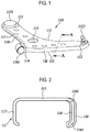
FIG. 1 is a front perspective view of a hybrid lower arm according to an embodiment of the present disclosure. -
FIG. 2 is a sectional view of part A inFIG. 1 . -
FIG. 3 is a partially cut-away perspective view of a hybrid lower arm according to an embodiment of the present disclosure. -
FIG. 4 is a perspective view showing a metal member of a hybrid lower arm according to an embodiment of the present disclosure. -
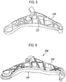
FIG. 5 is a perspective view showing a guard member of a hybrid lower arm according to an embodiment of the present disclosure. -
FIG. 6 is a rear perspective view of a hybrid lower arm according to an embodiment of the present disclosure. -
FIG. 7 is a top view of a hybrid lower arm provided at a rear wheel according to another embodiment of the present disclosure. -
FIG. 8 is an exploded perspective view showing a mounting state of a lower arm according to a prior art technology. -
FIG. 9 is a front perspective view of a lower arm according to a prior art technology. -
FIG. 10 is a sectional view of part B inFIG. 9 . - Hereinafter, detailed descriptions are made as to preferred embodiments of the present disclosure with reference to the accompanying drawings.
- Throughout the entire specification, a part may be described as "including" a certain constituent element. This means, unless specifically described otherwise, that such a part does not exclude other constituent elements, but may further include other constituent elements.
- Throughout the entire specification, parts denoted by the same reference numerals mean the same or similar constituent elements.
-
FIG. 1 is a front perspective view of a hybrid lower arm according to an embodiment of the present disclosure.FIG. 2 is a sectional view of part A inFIG. 1 .FIG. 3 is a partially cut-away perspective view of a hybrid lower arm according to an embodiment of the present disclosure.FIG. 4 is a perspective view showing a metal member of a hybrid lower arm according to an embodiment of the present disclosure.FIG. 5 is a perspective view showing a guard member of a hybrid lower arm according to an embodiment of the present disclosure.FIG. 6 is a rear perspective view of a hybrid lower arm according to an embodiment of the present disclosure. - For ease of explanation, a left side in a drawing is referred to as "one side," "one end," "one end portion" or a name similar thereto, and a right side in a drawing is referred to as an "opposite side," an "opposite end," an "opposite end portion," or a name similar thereto.
- Referring to
FIGS. 1 and 2 , a hybridlower arm 100 according to an embodiment of the present disclosure is formed in an approximately L-like shape, and includes ametal member 110 and aguard member 120. - The
metal member 110 is formed of a steel or aluminum material, and includes abody portion 111 and aface portion 131. - The
body portion 111 is formed in an approximately plate shape, and edges of thebody portion 111 are bent in a vertical direction of the drawing. Thebody portion 111 may be formed with three end portions. Aball joint hole 112 is formed at one end portion of the three end portions, a firstbush connection hole 113 is formed at another end portion of the three end portions, and a secondbush connection portion 114 is formed at the other end portion of the three end portions. Further, acenter hole 115 is formed at a center of thebody portion 111 among the three end portions. Afirst bent portion 1161 is formed at the edge of thebody portion 111. Theface portion 131 extends along thefirst bent portion 1161 toward a lower side of the drawing. - As described above, the
body portion 111 is formed with the balljoint hole 112, the firstbush connection hole 113, the secondbush connection portion 114, and thecenter hole 115. - The ball
joint hole 112 is formed so as to perforate in the vertical direction at the one end portion of thebody portion 111. A ball joint 1121 may be fixedly provided at the balljoint hole 112 and may connect with a vehicular wheel. - The first
bush connection hole 113 is formed so as to perforate in the vertical direction at the another end portion of thebody portion 111. Afirst bush 1131 is provided at the firstbush connection hole 113. Thefirst bush 1131 is coupled to a vehicular body. - The second
bush connection portion 114 protrudes from a side surface of the other end portion of thebody portion 111. The secondbush connection portion 114 has a hollow cylindrical shape, and asecond bush 1141 is provided at an inner side of the second bush connection portion. - The
center hole 115 is formed among the balljoint hole 112, the firstbush connection hole 113, and the secondbush connection portion 114. Thecenter hole 115 is formed to perforate in the vertical direction. A shock absorber is connected through thecenter hole 115. - The
face portion 131 is formed so as to be bent in the vertical direction at the edge of thebody portion 111. Theface portion 131 includes afirst face portion 116, asecond face portion 117, and athird face portion 118. The first, second, andthird face portions body portion 111. - Hereinafter, a downward direction of the
body portion 111 and a direction toward a portion surrounded by the first, second, andthird face portions - The
first face portion 116 is formed so as to extend from the edge of thebody portion 111 toward the lower side of the drawing between the balljoint hole 112 and the secondbush connection portion 114. A second bent portion 1163 is bent inward at a lower end of thefirst face portion 116. - The
second face portion 117 extends downwards from the edge of thebody portion 111 between the balljoint hole 112 and the firstbush connection hole 113. Thesecond face portion 117 is formed to bend arcuately. The second bent portion 1163 is bent inward at a lower end of thesecond face portion 117. - The
third face portion 118 is formed so as to extend downwards from the edge of thebody portion 111 between the firstbush connection hole 113 and the secondbush connection portion 114. - An inward surface of the
second face portion 117 is configured to face respective inward surfaces of thefirst face portion 116 and thethird face portion 118. - The
guard member 120 is formed of a plastic material by insert injection molding together with themetal member 110. For example, theguard member 120 may be formed of Glass Fiber Reinforced Plastic (GFRP). - According to an embodiment of the present disclosure, as shown in
FIG. 2 , theguard member 120 is configured to surround thefirst face portion 116 of themetal member 110. That is, theguard member 120 may be configured to surround the firstbent portion 1161, thefirst face portion 116, and the second bent portion 1163. Since the second bent portion 1163 is bent inward as described above, theguard member 120 is more firmly coupled to themetal member 110. - The
guard member 120 surrounding the firstbent portion 1161 is configured such that a height of theguard member 120 is aligned with an outer surface of thebody portion 111 in the vertical direction. Theguard member 120 is configured to cover the inner surface and the outer surface of the firstbent portion 1161, but does not extend to an upper surface and an outer surface of thebody portion 111. Accordingly, when compared with a guard member covering the entire surface of thebody portion 111, theguard member 120 can reduce the production cost or weight. Further, since theguard member 120 extends up to the bent portion, theguard member 120 is firmly mounted to themetal member 110 and demounting of the guard member is not easily facilitated. - Further, referring to
FIGS. 3 to 6 , theguard member 120 may be provided not only at thefirst face portion 116, but also at the inner side of themetal member 110. Theguard member 120 may be configured in a shape of surround theface portion 131 of themetal member 110 and the inner surface of thebody portion 111. That is, theguard member 120 may be provided so as to surround all of the inward surfaces, the lower surfaces, and the outward surfaces of theface portions - A
partition wall 121, which extends in the vertical direction in the same direction as the extension direction of theface portion 131, may be provided at an inner side of theguard member 120. Both sides of thepartition wall 121 are coupled to the inward surface of theface portion 131. For example, where one side of thepartition wall 121 is coupled to thefirst face portion 116, the opposite side of thepartition wall 121 is coupled to thesecond face portion 117 or thethird face portion 118. - The
partition wall 121 may be formed of a plurality of partition walls, and therespective partition walls 121 may be configured to intersect with each other. - As described above, since the plurality of the
partition walls 121 are formed with the above-described structure and support theface portion 131 of themetal member 110, theface portion 131 can be prevented from being damaged by an external impact. In particular, when an impact is applied from a front side due to a chipping phenomenon while the vehicle is being driven, thefirst face portion 116 of theguard member 110 can be prevented from cracking or being damaged. - The
guard member 120 is formed of a material different from themetal member 110. When theguard member 120 is formed of a material different from themetal member 110, a volume ratio of themetal member 110 is set in a range of 10% or more and less than 99%. - Since the
metal member 110 and theguard member 120 are formed of different materials, the hybridlower arm 100 according to an embodiment of the present disclosure has an effect of reduced weight when compared with a case where the metal member and the guard member are made of a single material. Further, since the lower end of theface portion 131 of themetal member 110 is bent inward, themetal member 110 and theguard member 120 can be prevented from being separated from each other. -
FIG. 7 is a top view of a hybrid lower arm provided at a rear wheel according to another embodiment. InFIG. 7 , a transverse direction of the drawing is referred to as a "length direction," a longitudinal direction of the drawing is referred to as a "width direction," and a direction perpendicular to the paper surface of the drawing is referred to as a "vertical direction." - As shown in
FIG. 7 , a hybridlower arm 200 according to another embodiment of the present disclosure is provided at a rear wheel of a vehicle, and includes abody portion 210, afirst coupling portion 220, and asecond coupling portion 230. - The
body portion 210 may be formed of a steel or aluminum material. Thebody portion 210 is formed in a shape of a plate extending in the length direction. Thebody portion 210 is formed in a shape of a gourd bottle. Similar to the above-described first embodiment, edges of thebody portion 210 are formed to bend in the vertical direction. - A spring seat hole, which is opened in the vertical direction, is formed at a center of the
body portion 210, and a hollowcylindrical spring seat 212 is mounted at an inner side of the spring seat hole. - Further, the
first coupling portion 220 and thesecond coupling portion 230 are formed at two ends of thebody portion 210 in the length direction. - The
first coupling portion 220 is formed to extend from one side of thebody portion 210, and is formed in a shape of a hollow body opened in the width direction. A bush is provided at an inner side of thefirst coupling portion 220. - The
second coupling portion 230 is formed at the opposite side of thebody portion 210, and extends from a surface which is formed when the edge of thebody portion 210 is bent in the vertical direction. Thesecond coupling portion 230 is formed with a hole perforating in the width direction. - According to another embodiment of the present disclosure, a
guard member 250 is provided at thebody portion 210. Theguard member 250 may be configured to surround a portion or the entirety of the faces which are bent from thebody portion 210 in the vertical direction. Accordingly, it is possible to prevent corrosion or damage caused by an external impact on the faces of thebody portion 210.
Claims (5)
- A hybrid lower arm comprising:a metal member including a plurality of end portions, one end portion of the plurality of end portions being connected to a ball joint and another end portion of the plurality of end portions being connected to a vehicular body;a face portion extending downwards along an edge of the metal member between the one end portion and the another end portion; anda guard member configured to surround a portion of the face portion and formed of a material lighter than the metal member.
- The hybrid lower arm of Claim 1, wherein a lower end of the face portion is bent toward an inner side of the metal member.
- The hybrid lower arm of Claim 2, wherein the guard member is formed of a plastic material and is configured to surround an inward surface, an outward surface, and a lower end surface of the face portion.
- The hybrid lower arm of Claim 1, wherein the metal member includes a body portion formed in a shape of an L-shaped plate,
wherein the guard member is formed to surround a lower surface of the body portion, an inward surface of the face portion, and an outward surface of the face portion, and
wherein the guard member is formed with a plurality of partition walls which extend downwards from the lower surface of the body portion to support the face portion and are connected to the face portion. - The hybrid lower arm of Claim 4, wherein the metal member is formed with three end portions,
wherein a ball joint hole is formed at one end portion of the three end portions, a first bush connection hole is formed at another end portion of the three end portions, a second bush connection portion is formed at the other end portion of the three end portions, and a center hole is formed among the three end portions, and
wherein the guard member is formed of a plastic material and is formed to surround an outward surface of the face portion formed in a vertical direction between the ball joint hole and the first bush connection portion, and to surround a bent portion of the body portion.
Applications Claiming Priority (2)
| Application Number | Priority Date | Filing Date | Title |
|---|---|---|---|
| KR1020150060781A KR101732066B1 (en) | 2015-04-29 | 2015-04-29 | Hybrid arm having a structure to prevent damage of painted surface due to chipping |
| PCT/KR2015/012626 WO2016175415A1 (en) | 2015-04-29 | 2015-11-24 | Hybrid lower arm |
Publications (2)
| Publication Number | Publication Date |
|---|---|
| EP3290241A1 true EP3290241A1 (en) | 2018-03-07 |
| EP3290241A4 EP3290241A4 (en) | 2018-12-05 |
Family
ID=57199565
Family Applications (1)
| Application Number | Title | Priority Date | Filing Date |
|---|---|---|---|
| EP15890856.6A Withdrawn EP3290241A4 (en) | 2015-04-29 | 2015-11-24 | Hybrid lower arm |
Country Status (6)
| Country | Link |
|---|---|
| US (1) | US20180154718A1 (en) |
| EP (1) | EP3290241A4 (en) |
| JP (1) | JP2018514463A (en) |
| KR (1) | KR101732066B1 (en) |
| CN (1) | CN107531117A (en) |
| WO (1) | WO2016175415A1 (en) |
Families Citing this family (5)
| Publication number | Priority date | Publication date | Assignee | Title |
|---|---|---|---|---|
| DE102014220443B4 (en) * | 2014-10-09 | 2021-12-23 | Ford Global Technologies, Llc | Handlebars for connecting a vehicle wheel to a vehicle and vehicle wheel suspension |
| WO2017115932A1 (en) * | 2015-12-30 | 2017-07-06 | 주식회사 일진 | Hybrid suspension arm for vehicle and manufacturing method therefor |
| KR101792137B1 (en) * | 2016-12-27 | 2017-11-02 | 주식회사 일진 | Hybrid suspension arm for vehicle |
| DE102019122721B4 (en) * | 2019-08-23 | 2025-01-02 | Benteler Automobiltechnik Gmbh | Chassis link and method for producing a chassis link |
| JP2025074848A (en) * | 2023-10-30 | 2025-05-14 | トヨタ自動車株式会社 | Suspension structure components |
Family Cites Families (28)
| Publication number | Priority date | Publication date | Assignee | Title |
|---|---|---|---|---|
| JPH03172635A (en) * | 1989-12-01 | 1991-07-26 | Nhk Spring Co Ltd | Suspension device for vehicle |
| US5267751A (en) * | 1991-04-05 | 1993-12-07 | Nhk Spring Co., Ltd. | Suspension system for a vehicle |
| JP3737837B2 (en) * | 1994-06-24 | 2006-01-25 | トヨタ自動車株式会社 | Vehicle suspension arm |
| JPH08188022A (en) * | 1995-01-11 | 1996-07-23 | F Tech:Kk | Vehicle suspension arm |
| JPH08318722A (en) * | 1995-03-23 | 1996-12-03 | Toyota Motor Corp | Suspension arm |
| JP3191654B2 (en) * | 1995-08-30 | 2001-07-23 | トヨタ自動車株式会社 | Suspension arm |
| JP3505899B2 (en) * | 1996-03-04 | 2004-03-15 | トヨタ自動車株式会社 | Vehicle suspension arm |
| JP3725031B2 (en) * | 2001-01-12 | 2005-12-07 | 本田技研工業株式会社 | Suspension arm |
| DE60304709T2 (en) * | 2003-07-07 | 2006-12-21 | Zf Friedrichshafen Ag | MOTOR VEHICLE SUSPENSION ARM |
| JP3966874B2 (en) * | 2004-08-23 | 2007-08-29 | 本田技研工業株式会社 | Vehicle suspension system |
| DE102005004917B4 (en) * | 2005-02-02 | 2013-02-28 | Benteler Automobiltechnik Gmbh | Handlebar component for wheel suspensions of motor vehicles and method for its production |
| DE102007015616B4 (en) * | 2007-03-29 | 2021-10-21 | Zf Friedrichshafen Ag | Connector for the articulated connection of components arranged in the chassis of a vehicle |
| DE102007015615B4 (en) * | 2007-03-29 | 2012-07-19 | Zf Friedrichshafen Ag | Connecting piece for the articulated connection of components arranged in the chassis of a vehicle |
| DE102007047191A1 (en) * | 2007-07-03 | 2009-01-08 | Hyundai Motor Company | Lower arm of a vehicle suspension |
| JP4924268B2 (en) * | 2007-07-26 | 2012-04-25 | 日産自動車株式会社 | Protective member |
| CA2611281A1 (en) * | 2007-11-20 | 2009-05-20 | Multimatic Inc. | Structural i-beam automotive suspension arm |
| BRPI0913995A2 (en) * | 2008-07-10 | 2015-10-20 | Honda Motor Co Ltd | vehicle suspension arm |
| JP2010111226A (en) * | 2008-11-05 | 2010-05-20 | F Tech:Kk | L-shaped suspension arm for vehicle |
| DE102009054999A1 (en) * | 2009-12-18 | 2011-06-22 | Henkel AG & Co. KGaA, 40589 | composite component |
| DE102010024634A1 (en) * | 2010-06-22 | 2011-12-22 | Benteler Automobiltechnik Gmbh | Motor vehicle drivers |
| KR101211419B1 (en) * | 2010-10-29 | 2012-12-12 | 주식회사화신 | Lower arm for vehicle |
| CN202192955U (en) * | 2011-09-06 | 2012-04-18 | 河北中兴汽车制造有限公司 | Automobile lower swing arm |
| CN202294121U (en) * | 2011-10-10 | 2012-07-04 | 索密克汽车配件有限公司 | Lower swing arm assembly |
| FR2993806B1 (en) * | 2012-07-26 | 2015-02-13 | Saint Jean Ind | PROCESS FOR MANUFACTURING STRUCTURE PARTS OF LIGHT ALLOY AND PARTS THUS OBTAINED FOR OPTIMIZING THE MASS / PERFORMANCE RATIO |
| KR101393849B1 (en) | 2012-12-12 | 2014-05-12 | 현대자동차주식회사 | Law arm for vehicle |
| JP6042231B2 (en) * | 2013-02-27 | 2016-12-14 | ダイハツ工業株式会社 | Front body structure of automobile |
| CN203331767U (en) * | 2013-06-25 | 2013-12-11 | 重庆长安汽车股份有限公司 | Automobile rear lower swing arm |
| KR101454624B1 (en) * | 2013-09-30 | 2014-10-27 | 주식회사화신 | Protector for link |
-
2015
- 2015-04-29 KR KR1020150060781A patent/KR101732066B1/en active Active
- 2015-11-24 EP EP15890856.6A patent/EP3290241A4/en not_active Withdrawn
- 2015-11-24 JP JP2018509713A patent/JP2018514463A/en active Pending
- 2015-11-24 CN CN201580079301.0A patent/CN107531117A/en not_active Withdrawn
- 2015-11-24 US US15/569,930 patent/US20180154718A1/en not_active Abandoned
- 2015-11-24 WO PCT/KR2015/012626 patent/WO2016175415A1/en not_active Ceased
Also Published As
| Publication number | Publication date |
|---|---|
| JP2018514463A (en) | 2018-06-07 |
| CN107531117A (en) | 2018-01-02 |
| US20180154718A1 (en) | 2018-06-07 |
| WO2016175415A1 (en) | 2016-11-03 |
| KR101732066B1 (en) | 2017-05-08 |
| EP3290241A4 (en) | 2018-12-05 |
| KR20160129202A (en) | 2016-11-09 |
Similar Documents
| Publication | Publication Date | Title |
|---|---|---|
| US10442262B2 (en) | Hybrid arm and method of manufacturing same | |
| EP3290241A1 (en) | Hybrid lower arm | |
| US20090008891A1 (en) | Lower arm of vehicle suspension | |
| US10124640B2 (en) | Vehicle suspension member | |
| US20180370576A1 (en) | Vehicle body structure | |
| JP6507554B2 (en) | Vehicle packing box mounting bracket | |
| US9579946B2 (en) | Trailing arm bush for coupled torsion beam axle | |
| WO2017021181A1 (en) | Pneumatic axle suspension for a rear axle of a vehicle | |
| US10577021B2 (en) | Vehicle sub-frame | |
| KR20170026617A (en) | Spring bracket arm | |
| US7213825B2 (en) | Leaf spring retaining bracket | |
| CN103991349A (en) | Reinforcing structure of rear spring seat | |
| US9387885B2 (en) | Connecting device for connecting a vehicle sub-frame and a vehicle body and vehicle comprising the same | |
| JP5452683B1 (en) | Stabilizer bracket | |
| US8991839B1 (en) | Axle suspension system | |
| CN204279633U (en) | A kind of punch and weld C ellbeam for air suspension of automobile | |
| KR101220372B1 (en) | Sub frame of suspension system for vehicle | |
| KR101692622B1 (en) | Halftype sub frame for automobile | |
| KR102097145B1 (en) | Suspension arm for a motor vehicle intended to absorb a side impact | |
| KR101624506B1 (en) | Camber angle variable rear axle | |
| CN106427516A (en) | Torsion resistant pull rod of power assembly | |
| US10549593B2 (en) | Wheel suspension for a motor vehicle | |
| CN205010323U (en) | Sub vehicle frame assembly and vehicle | |
| KR20150067976A (en) | Trailing arm bush | |
| CN205801245U (en) | Mounting bracket of shock absorber, rear overhang installation assembly and rear overhang mounting structure |
Legal Events
| Date | Code | Title | Description |
|---|---|---|---|
| PUAI | Public reference made under article 153(3) epc to a published international application that has entered the european phase |
Free format text: ORIGINAL CODE: 0009012 |
|
| 17P | Request for examination filed |
Effective date: 20171102 |
|
| AK | Designated contracting states |
Kind code of ref document: A1 Designated state(s): AL AT BE BG CH CY CZ DE DK EE ES FI FR GB GR HR HU IE IS IT LI LT LU LV MC MK MT NL NO PL PT RO RS SE SI SK SM TR |
|
| AX | Request for extension of the european patent |
Extension state: BA ME |
|
| DAV | Request for validation of the european patent (deleted) | ||
| DAX | Request for extension of the european patent (deleted) | ||
| A4 | Supplementary search report drawn up and despatched |
Effective date: 20181029 |
|
| RIC1 | Information provided on ipc code assigned before grant |
Ipc: B60G 7/00 20060101ALI20181023BHEP Ipc: B60G 7/04 20060101ALI20181023BHEP Ipc: B60G 7/02 20060101AFI20181023BHEP Ipc: F16D 3/22 20060101ALI20181023BHEP |
|
| 17Q | First examination report despatched |
Effective date: 20190716 |
|
| STAA | Information on the status of an ep patent application or granted ep patent |
Free format text: STATUS: THE APPLICATION HAS BEEN WITHDRAWN |
|
| 18W | Application withdrawn |
Effective date: 20190816 |