EP3290233B1 - Tire - Google Patents
Tire Download PDFInfo
- Publication number
- EP3290233B1 EP3290233B1 EP17180678.9A EP17180678A EP3290233B1 EP 3290233 B1 EP3290233 B1 EP 3290233B1 EP 17180678 A EP17180678 A EP 17180678A EP 3290233 B1 EP3290233 B1 EP 3290233B1
- Authority
- EP
- European Patent Office
- Prior art keywords
- oblique
- groove
- tire
- grooves
- sub
- Prior art date
- Legal status (The legal status is an assumption and is not a legal conclusion. Google has not performed a legal analysis and makes no representation as to the accuracy of the status listed.)
- Active
Links
- 238000010008 shearing Methods 0.000 description 5
- 230000001133 acceleration Effects 0.000 description 3
- 239000010426 asphalt Substances 0.000 description 2
- 230000007423 decrease Effects 0.000 description 2
- 238000006243 chemical reaction Methods 0.000 description 1
- 230000003247 decreasing effect Effects 0.000 description 1
- 238000006073 displacement reaction Methods 0.000 description 1
- 230000000694 effects Effects 0.000 description 1
- 238000005516 engineering process Methods 0.000 description 1
- 238000010998 test method Methods 0.000 description 1
Images

Classifications
-
- B—PERFORMING OPERATIONS; TRANSPORTING
- B60—VEHICLES IN GENERAL
- B60C—VEHICLE TYRES; TYRE INFLATION; TYRE CHANGING; CONNECTING VALVES TO INFLATABLE ELASTIC BODIES IN GENERAL; DEVICES OR ARRANGEMENTS RELATED TO TYRES
- B60C11/00—Tyre tread bands; Tread patterns; Anti-skid inserts
- B60C11/03—Tread patterns
- B60C11/0306—Patterns comprising block rows or discontinuous ribs
- B60C11/0309—Patterns comprising block rows or discontinuous ribs further characterised by the groove cross-section
-
- B—PERFORMING OPERATIONS; TRANSPORTING
- B60—VEHICLES IN GENERAL
- B60C—VEHICLE TYRES; TYRE INFLATION; TYRE CHANGING; CONNECTING VALVES TO INFLATABLE ELASTIC BODIES IN GENERAL; DEVICES OR ARRANGEMENTS RELATED TO TYRES
- B60C11/00—Tyre tread bands; Tread patterns; Anti-skid inserts
- B60C11/03—Tread patterns
- B60C11/0302—Tread patterns directional pattern, i.e. with main rolling direction
-
- B—PERFORMING OPERATIONS; TRANSPORTING
- B60—VEHICLES IN GENERAL
- B60C—VEHICLE TYRES; TYRE INFLATION; TYRE CHANGING; CONNECTING VALVES TO INFLATABLE ELASTIC BODIES IN GENERAL; DEVICES OR ARRANGEMENTS RELATED TO TYRES
- B60C11/00—Tyre tread bands; Tread patterns; Anti-skid inserts
- B60C11/03—Tread patterns
- B60C11/0327—Tread patterns characterised by special properties of the tread pattern
- B60C11/0332—Tread patterns characterised by special properties of the tread pattern by the footprint-ground contacting area of the tyre tread
-
- B—PERFORMING OPERATIONS; TRANSPORTING
- B60—VEHICLES IN GENERAL
- B60C—VEHICLE TYRES; TYRE INFLATION; TYRE CHANGING; CONNECTING VALVES TO INFLATABLE ELASTIC BODIES IN GENERAL; DEVICES OR ARRANGEMENTS RELATED TO TYRES
- B60C11/00—Tyre tread bands; Tread patterns; Anti-skid inserts
- B60C11/03—Tread patterns
- B60C11/12—Tread patterns characterised by the use of narrow slits or incisions, e.g. sipes
- B60C11/1272—Width of the sipe
-
- B—PERFORMING OPERATIONS; TRANSPORTING
- B60—VEHICLES IN GENERAL
- B60C—VEHICLE TYRES; TYRE INFLATION; TYRE CHANGING; CONNECTING VALVES TO INFLATABLE ELASTIC BODIES IN GENERAL; DEVICES OR ARRANGEMENTS RELATED TO TYRES
- B60C11/00—Tyre tread bands; Tread patterns; Anti-skid inserts
- B60C11/03—Tread patterns
- B60C2011/0337—Tread patterns characterised by particular design features of the pattern
- B60C2011/0339—Grooves
- B60C2011/0341—Circumferential grooves
-
- B—PERFORMING OPERATIONS; TRANSPORTING
- B60—VEHICLES IN GENERAL
- B60C—VEHICLE TYRES; TYRE INFLATION; TYRE CHANGING; CONNECTING VALVES TO INFLATABLE ELASTIC BODIES IN GENERAL; DEVICES OR ARRANGEMENTS RELATED TO TYRES
- B60C11/00—Tyre tread bands; Tread patterns; Anti-skid inserts
- B60C11/03—Tread patterns
- B60C2011/0337—Tread patterns characterised by particular design features of the pattern
- B60C2011/0339—Grooves
- B60C2011/0358—Lateral grooves, i.e. having an angle of 45 to 90 degees to the equatorial plane
-
- B—PERFORMING OPERATIONS; TRANSPORTING
- B60—VEHICLES IN GENERAL
- B60C—VEHICLE TYRES; TYRE INFLATION; TYRE CHANGING; CONNECTING VALVES TO INFLATABLE ELASTIC BODIES IN GENERAL; DEVICES OR ARRANGEMENTS RELATED TO TYRES
- B60C11/00—Tyre tread bands; Tread patterns; Anti-skid inserts
- B60C11/03—Tread patterns
- B60C2011/0337—Tread patterns characterised by particular design features of the pattern
- B60C2011/0339—Grooves
- B60C2011/0374—Slant grooves, i.e. having an angle of about 5 to 35 degrees to the equatorial plane
- B60C2011/0376—Slant grooves, i.e. having an angle of about 5 to 35 degrees to the equatorial plane characterised by width
-
- B—PERFORMING OPERATIONS; TRANSPORTING
- B60—VEHICLES IN GENERAL
- B60C—VEHICLE TYRES; TYRE INFLATION; TYRE CHANGING; CONNECTING VALVES TO INFLATABLE ELASTIC BODIES IN GENERAL; DEVICES OR ARRANGEMENTS RELATED TO TYRES
- B60C11/00—Tyre tread bands; Tread patterns; Anti-skid inserts
- B60C11/03—Tread patterns
- B60C2011/0337—Tread patterns characterised by particular design features of the pattern
- B60C2011/0339—Grooves
- B60C2011/0381—Blind or isolated grooves
-
- B—PERFORMING OPERATIONS; TRANSPORTING
- B60—VEHICLES IN GENERAL
- B60C—VEHICLE TYRES; TYRE INFLATION; TYRE CHANGING; CONNECTING VALVES TO INFLATABLE ELASTIC BODIES IN GENERAL; DEVICES OR ARRANGEMENTS RELATED TO TYRES
- B60C11/00—Tyre tread bands; Tread patterns; Anti-skid inserts
- B60C11/03—Tread patterns
- B60C11/12—Tread patterns characterised by the use of narrow slits or incisions, e.g. sipes
- B60C11/1272—Width of the sipe
- B60C2011/1286—Width of the sipe being different from sipe to sipe
Landscapes
- Engineering & Computer Science (AREA)
- Mechanical Engineering (AREA)
- Tires In General (AREA)
Description
- The present invention relates to a tire capable of exerting excellent on-snow performance. The features of the preamble of the independent claim are known from
EP 2 230 100 A1US 2016/152091 A1 andEP 2 692 543 A1 - For example, Japanese Unexamined Patent Application Publication No.
2013-136333 - However, the tire disclosed in Patent Literature 1 has room for further improvement as to the on-snow performance.
- The present invention was made in view of the above, and a primary object thereof is to provide a tire capable of exerting excellent on-snow performance by improving arrangement of grooves. The present invention is defined in the independent claim.
- In one aspect of the present invention, a tire comprises a tread portion comprising a first tread portion defined between a tire equator C and a first tread edge. The first tread portion is provided with a crown main groove extending continuously and straight in a tire circumferential direction on a side of the tire equator C and a plurality of oblique main grooves extending obliquely from the first tread edge toward the tire equator C to cross the crown main groove to form a plurality of oblique land regions each defined between a pair of oblique main grooves adjacent in the tire circumferential direction. And at least one of the oblique land regions is provided with an inner oblique sub-groove extending from one of the oblique main grooves and terminating within the at least one of the oblique land regions on an outer side of the crown main groove in a tire axial direction and an outer oblique sub-groove disposed on the outer side of the inner oblique sub-groove in the tire axial direction and connecting between a pair of the oblique main grooves adjacent to both sides of the at least one of the oblique land regions.
- In another aspect of the invention, it is preferred that the inner oblique sub-groove is inclined to an opposite direction to the oblique main grooves.
- In another aspect of the invention, it is preferred that the outer oblique sub-groove is inclined to the opposite direction to the oblique main grooves.
- In another aspect of the invention, it is preferred that the outer oblique sub-groove is inclined with respect to the tire circumferential direction at an angle smaller than the inner oblique sub-groove.
- In another aspect of the invention, it is preferred that the oblique main grooves has groove widths larger than that of the crown main groove at least in a region on the outer side of the crown main groove in the tire axial direction.
- In another aspect of the invention, it is preferred that a distance in the tire axial direction between the tire equator and a groove center line of the crown main groove is in a range of from 0.10 to 0.20 times a tread width.
- In another aspect of the invention, it is preferred that an angle between the crown main groove and the oblique main grooves is in a range of from 30 to 60 degrees.
-
-
Fig. 1 is a development view of a tread portion of a tire as an embodiment of the present invention. -
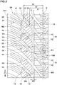
Fig. 2 is an enlarged view of a first tread portion ofFig. 1 . -
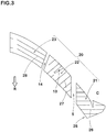
Fig. 3 is a partial enlarged view of an oblique land region ofFig. 2 . -
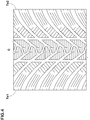
Fig. 4 is a development view of the tread portion of a tire as reference 1. -
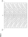
Fig. 5 is a development view of the tread portion of a tire asreference 2. - An embodiment of the present invention will now be described in conjunction with accompanying drawings.
-
Fig. 1 is a development view of atread portion 2 of a tire 1 in this embodiment. The tire 1 in this embodiment is suitably used as a winter tire for a passenger car, for example. Further, the tire 1 in this embodiment is provided with a directional pattern in which a rotational direction R is specified. The rotational direction R is indicated on a sidewall portion (not shown) by characters or symbols, for example. - As shown in
Fig. 1 , thetread portion 2 of the tire 1 in this embodiment includes afirst tread portion 2A defined between the tire equator C and a first tread edge Te1, and asecond tread portion 2B defined between the tire equator C and a second tread edge Te2. - The first tread edge Te1 and the second tread edge Te2 are the outermost ground contacting positions of the tire 1 in a tire axial direction when the tire 1 in a standard state is in contact with a flat surface with zero camber angle by being loaded with a standard load. The standard state is a state in which the tire is mounted on a standard rim and inflated to a standard pressure with no tire load. Sizes and the like of various parts of the tire in this specification are those measured in the standard state unless otherwise noted.
- The "standard rim" is a wheel rim specified for the concerned tire by a standard included in a standardization system on which the tire is based, for example, the "normal wheel rim" in JATMA, "Design Rim" in TRA, and "Measuring Rim" in ETRTO.
- The "standard pressure" is air pressure specified for the concerned tire by a standard included in a standardization system on which the tire is based, for example, the "maximum air pressure" in JATMA, maximum value listed in the "TIRE LOAD LIMITS AT VARIOUS COLD INFLATION PRESSURES" table in TRA, and "INFLATION PRESSURE" in ETRTO.
- The "standard load" is a tire load specified for the concerned tire by a standard included in a standardization system on which the tire is based, for example, the "maximum load capacity" in JATMA, maximum value listed in "TIRE LOAD LIMITS AT VARIOUS COLD INFLATION PRESSURES" table in TRA, and "LOAD CAPACITY" in ETRTO.
- Each of the
first tread portion 2A and thesecond tread portion 2B is provided with a crownmain groove 5, a plurality of obliquemain grooves 10, andoblique land regions 20 each defined between a pair of the obliquemain grooves 10 adjacent in the tire circumferential direction. Thefirst tread portion 2A and thesecond tread portion 2B have substantially the same configuration. Hereinafter, the configurations of the crownmain groove 5, the obliquemain grooves 10 and theoblique land regions 20 provided in thefirst tread portion 2A will be described, and the description of those provided in thesecond tread portion 2B will be omitted. -
Fig. 2 is an enlarged view of thefirst tread portion 2A. As shown inFig. 2 , the crownmain groove 5 extends straight on a side of the tire equator C. The crownmain groove 5 in this embodiment is provided, for example, on the side of the tire equator C of a center position in the tire axial direction between the tire equator C and the first tread edge Te1. - Specifically, it is preferred that a distance L1 between the tire equator C and a groove center line of the crown
main groove 5 is, for example, in a range of from 0.10 to 0.20 times a tread width TW (shown inFig. 1 and the same hereinafter). The tread width TW is a distance in the tire axial direction between the first tread edge Te1 and the second tread edge Te2 when the tire is in the standard state. - It is preferred that a groove width w1 of the crown
main groove 5 is in a range of from 1.5% to 4.5% of the tread width TW, for example. - The crown
main groove 5 configured as such can form a long snow block extending in the tire circumferential direction when running on a snowy road and consequently large snow shearing force in the tire axial direction can be obtained. - The oblique
main grooves 10 extend obliquely from the first tread edge Te1 toward the tire equator C to cross the crownmain groove 5. The obliquemain grooves 10 form long snow blocks extending obliquely with respect to the tire axial direction and then shear the snow blocks when running on a snowy road, therefore, it is possible that large traction is obtained. - Each of the oblique
main grooves 10 in this embodiment includes, for example, amain body portion 11 extending from the first tread edge Te1 to an area between the crownmain groove 5 and the tire equator C, and aninner portion 12 connected with themain body portion 11 on the side of the tire equator C. - Each of the
main body portions 11, for example, extends from the first tread edge Te1 toward the tire equator C with a gradually decreasing angle θ1 with respect to the tire circumferential direction. It is preferred that the angle θ1 of themain body portions 11 is in a range of from 15 to 75 degrees, for example. Themain body portions 11 configured as such exert shearing force in the tire axial direction as well, therefore, it is useful for improving cornering performance on a snowy road. - An angle θ2 between the crown
main groove 5 and themain body portions 11 of the obliquemain grooves 10 is preferably not less than 30 degrees, more preferably not less than 40 degrees, and preferably not greater than 60 degrees, more preferably not greater than 50 degrees. Themain body portions 11 configured as such can exert the above-mentioned effects without impairing drainage performance of the crownmain groove 5 during running on a wet road surface. - It is preferred that the
main body portions 11 are configured so that, for example, groove widths w2 thereof gradually decreases axially inwardly. It is preferred that the groove widths W2 of themain body portions 11 is in a range of from 2% to 7% of the tread width TW, for example. Themain body portions 11 configured as such are useful for improving the on-snow performance and wet performance while maintaining steering stability on a dry road surface. - In order to further improve the on-snow performance and the wet performance, it is preferred that the
main body portions 11 have the groove widths larger than the groove widths of the crownmain grooves 5 at least in a region on an outer side of the crownmain grooves 5 in the tire axial direction. - Each of the
inner portion 12 is connected with one of themain body portions 11 on a toe-side in the rotational direction R (hereinafter may be simply referred to as "toe-side") of an end of themain body portion 11. In other words, theinner portions 12 diverge from themain body portions 11 to extend toward the tire equator C. - The
inner portions 12 extend straight and obliquely in a same direction as themain body portions 11, for example. Each of theinner portions 12 crosses the tire equator C, for example, to be connected with one of obliquemain grooves 10B provided in thesecond tread portion 2B. Generally speaking, large ground contact pressure is applied to the tire on an area around the tire equator C during running, therefore, theinner portions 12 can strongly compress the snow, thereby, it is possible that excellent on-snow traction is exerted. - In order to exert the shearing force in the tire axial direction as well, it is preferred that an angle θ3 of the
inner portions 12 with respect to the tire axial direction is in a range of from 10 to 30 degrees, for example. - At least one of the
oblique land regions 20 is provided with aninner oblique sub-groove 13 extending from one of the obliquemain grooves 10 adjacent to the at least one of theoblique land regions 20 and terminating within theoblique land region 20 on the axially outside of the crownmain groove 5, and anouter oblique sub-groove 14 crossing theoblique land region 20 on the axially outside of theinner oblique sub-groove 13. Each of theoblique land regions 20 in this embodiment is provided with theinner oblique sub-groove 13 and the outer oblique sub-groove. - Generally, when running on a snowy road, the snow that has entered the oblique
main grooves 10 tends to be compressed while moving to each of the sub-grooves. Each of theinner oblique sub-groove 13 and theouter oblique sub-groove 14 of the present invention compresses and then shears the snow entering from the obliquemain grooves 10, therefore, it is possible that the on-snow performance is further improved. Further, in general, a larger ground contact pressure is applied to the inner oblique sub-grooves 13, which are disposed on the axially inside, than to theouter oblique sub-grooves 14. However, theinner oblique sub-grooves 13 of the present invention terminates within theoblique land regions 20, therefore, it is possible that the snow moved from the obliquemain grooves 10 is compressed harder when running on a snowy road, and consequently large shearing force is obtained. - Moreover, the
outer oblique sub-grooves 14 crossing theoblique land region 20 are provided axially outside the inner oblique sub-grooves 13, therefore, land region pieces provided with theinner oblique sub-grooves 13 are each surrounded by the crownmain groove 5, the obliquemain grooves 10, and theouter oblique sub-groove 14. Thereby, it is possible that the land region pieces can be appropriately deformed when running on a snowy road, and consequently it is possible that clogging of snow in theinner oblique sub-groove 13 is suppressed. - Each of the inner oblique sub-grooves 13, for example, is connected with one of the oblique
main grooves 10 adjacent on the toe-side to theoblique land region 20 and extends obliquely toward the first tread edge Te1 to a heel-side in the rotational direction R (hereinafter may be simply referred to as "heel-side"). In other words, theinner oblique sub-grooves 13 are inclined to an opposite direction to the obliquemain grooves 10. As a preferred embodiment, the inner oblique sub-grooves 13 in this embodiment are smoothly curved. - An angle θ4 of the inner oblique sub-grooves 13 with respect to the oblique
main grooves 10 is preferably not less than 70 degrees, more preferably not less than 75 degrees, and preferably not greater than 90 degrees, more preferably not greater than 85 degrees. Thereby, it is possible that the on-snow performance is improved while uneven wear of the land region pieces provided with theinner oblique sub-grooves 13 is suppressed. - In order to improve the on-snow performance while suppressing uneven wear of the
oblique land regions 20, it is preferred that a distance L2 in the tire axial direction between the tire equator C and anintersection 15 of an extended groove center line of one of theinner oblique sub-groove 13 and a groove center line of one of the obliquemain groove 10 is in a range of from 0.15 to 0.25 times the tread width TW, for example. - It is preferred that groove widths W3 of the
inner oblique sub-grooves 13 gradually decrease towardend portions 16 which terminate within theoblique land regions 20, for example. Thereby, during running on a snowy road, the snow in theinner oblique sub-grooves 13 is likely to be discharged as theoblique land regions 20 are deformed. It is preferred that the groove widths W3 of theinner oblique sub-grooves 13 are in a range of from 1% to 3% of the tread width TW, for example. - It is preferred that each of the
outer oblique sub-grooves 14 is inclined to the tire equator C, for example, connecting between the obliquemain grooves 10 adjacent on the heel-side and on the toe-side. In other words, theouter oblique sub-grooves 14 are inclined to the opposite direction to the obliquemain grooves 10. - An angle θ5 of the outer oblique sub-grooves 14 with respect to the oblique
main grooves 10 is preferably not less than 60 degrees, more preferably not less than 65 degrees, and preferably not greater than 80 degrees, more preferably not greater than 75 degrees. Theouter oblique sub-grooves 14 configured as such can form snow blocks extending in a direction different from that of the obliquemain grooves 10 while suppressing the uneven wear of theoblique land regions 20, and consequently it is possible that the cornering performance on the snow is improved. - As a further preferred embodiment, the outer oblique sub-grooves 14 in this embodiment are inclined at an angle smaller than the inner oblique sub-grooves 13 with respect to the tire circumferential direction. Thereby, when running on a snowy road, the outer oblique sub-grooves 14 and the
inner oblique sub-grooves 13 exert the shearing force in different directions, and consequently the on-snow performance is improved. - It is preferred that a distance L3 in the tire axial direction between the tire equator C and an
intersection 18 of an extended groove center line of one of the outer oblique sub-grooves 14 and the groove center line of one of the obliquemain grooves 10 provided on the toe-side thereof is in a range of from 0.20 to 0.30 times the tread width TW, for example. Thereby, the on-snow performance is improved while the uneven wear of theoblique land regions 20 is suppressed. - It is preferred that the outer oblique sub-grooves 14 in this embodiment extend straight with constant groove widths w4, for example. It is preferred that the groove widths w4 of the
outer oblique sub-grooves 14 are in a range of from 1% to 3% of the tread width TW, for example. Thereby, clogging of snow in theouter oblique sub-grooves 14 is suppressed. -
Fig. 3 is an enlarged view of one of theoblique land regions 20. As shown inFig. 3 , each of theoblique land regions 20 is divided into acrown block 21, amiddle block 22, and ashoulder block 23 by the crownmain groove 5 and theouter oblique sub-groove 14 described above. - The crown blocks 21 is provided on the axially inside of the crown
main groove 5 and extends beyond the tire equator C, for example. - It is preferred that the crown blocks 21 in this embodiment each have a
tip portion 25 convex toward the heel-side in the rotational direction R, for example. It is preferred that each of thetip portions 25 in this embodiment has a v-shaped edge convex toward the heel-side. With thetip portions 25 configured as such, the edges thereof stick into the road surface when running on ice, for example, therefore, large reaction force is obtained. - It is preferred that each of the crown blocks 21 is provided with a plurality of
crown sipes 26 extending along the tire axial direction. The crown sipes 26 configured as such can provide large traction when running on ice. - The middle blocks 22 are provided between the crown
main groove 5 and theouter oblique sub-grooves 14. Each of the middle blocks 22 is formed substantially in a rectangular shape, for example, except that one of theinner oblique sub-grooves 13 is formed therein. The middle blocks 22 in this embodiment are each formed in a horizontally elongated shape along a longitudinal direction of the obliquemain grooves 10, for example. The middle blocks 22 configured as such deform moderately in the tire circumferential direction when running on a snowy road, therefore, it helps to discharge the snow in the obliquemain grooves 10. - It is preferred that each of the middle blocks 22 is provided with
middle sipes 27 inclined to the opposite direction to the obliquemain grooves 10, for example. Themiddle sipes 27 configured as such can exert frictional force in many directions during running on ice. - The shoulder blocks 23 are provided between the outer oblique sub-grooves 14 and the first tread edge Te1. Each of the shoulder blocks 23 is formed in a horizontally elongated rectangular shape along the longitudinal direction of the oblique
main grooves 10, for example. - It is preferred that each of the shoulder blocks 23 is provided with
shoulder sipes 28 inclined to a same direction as the obliquemain grooves 10, for example. The shoulder sipes 28 configured as such makes rigidity of the shoulder blocks 23 moderate, therefore, it is possible that excellent wandering performance is exerted. - While detailed description has been made of the tire as an embodiment of the present invention, the present invention can be embodied in various forms without being limited to the illustrated embodiment.
- Tires of size 255/55R18 having a basic tread pattern shown in
Fig. 1 were made by way of test according to the specification listed in Table 1. As Reference 1, as shown inFig. 4 , a tire not provided with the inner oblique sub-grooves and the outer oblique sub-grooves was made by way of test. AsReference 2, as shown inFig. 5 , a tire provided with the outer oblique sub-grooves but not provided with the inner oblique sub-grooves was made by way of test. The on-snow performance, the wet performance, and anti-wear performance were tested for each of the test tires. Common specifications of the test tires and the test methods are as follows. - Tire pressure: 230 kPa (front wheels), 250 kPa (rear wheels)
- A distance needed for accelerating the above test car from 5 km/h to 20 km/h on a snowy road was measured by GPS and an average acceleration was calculated. The results are indicated by an index based on the average acceleration of the Reference 1 being 100, wherein the larger the numerical value, the better the on-snow performance is.
- By using the above test car, lateral acceleration (lateral G) of the front wheels was measured while running on an asphalt road surface having a radius of 100 m and provided with a puddle of 10 mm in depth and 20 m in length. The results are average lateral G at a speed of 55 to 80 km/h and indicated by an index based on the value of the Reference 1 being 100, wherein the larger the numerical value, the better the wet performance is.
- Amount of wear of the oblique land regions after driving the test car for a certain distance on an asphalt road surface was measured. The results are indicated by an index based on the Reference 1 being 100, wherein the smaller the numerical value, the better the anti-wear performance is. The test results are shown in Table 1.
Table 1. (1/2) Ref. 1 Ref. 2 Ex.1 Ex.2 Ex.3 Ex.4 Ex.5 Ex.6 Ex.7 Figure showing Tread pattern Fig. 4 Fig. 5 Fig. 1 Fig. 1 Fig. 1 Fig. 1 Fig. 1 Fig. 1 Fig. 1 Distance L1 between Tire equator and Crown main groove/ Tread width TW 0.14 0.14 0.14 0.10 0.13 0.17 0.20 0.14 0.14 Angle θ2 between Crown main groove and Oblique main grooves [degree] 45 45 45 45 45 45 45 30 40 Angle θ4 of Inner oblique sub-groove [degree] - - 80 80 80 80 80 80 80 Angle θ5 of Outer oblique sub-groove [degree] - 70 70 70 70 70 70 70 70 On-snow performance [index] 100 104 110 108 110 110 109 108 110 Wet performance [index] 100 103 105 106 106 104 104 103 104 Anti-wear performance [index] 100 102 102 104 103 102 102 102 102 Table 1. (2/2) Ex. 8 Ex. 9 Ex. 10 Ex. 11 Ex. 12 Ex. 13 Ex. 14 Ex. 15 Ex. 16 Ex. 17 Figure showing Tread pattern Fig. 1 Fig. 1 Fig. 1 Fig. 1 Fig. 1 Fig. 1 Fig. 1 Fig. 1 Fig. 1 Fig. 1 Distance L1 between Tire equator and Crown main groove/ Tread width TW 0.14 0.14 0.14 0.14 0.14 0.14 0.14 0.14 0.14 0.14 Angle θ2 between Crown main groove and Oblique main grooves [degree] 50 60 45 45 45 45 45 45 45 45 Angle θ4 of Inner oblique sub-groove [degree] 80 80 70 75 85 90 80 80 80 80 Angle θ5 of Outer oblique sub-groove [degree] 70 70 70 70 70 70 60 65 75 80 On-snow performance [index] 110 109 110 110 109 109 109 110 109 109 Wet performance [index] 105 106 104 104 105 106 106 105 105 104 Anti-wear performance [index] 104 105 104 102 102 104 104 102 102 103 - From the test results, it was confirmed that the on-snow performance and the wet performance of the tires as the Examples were improved. Further, it was confirmed that the tires as the Examples maintained the anti-wear performance.
Claims (7)
- A tire (1) comprising:a tread portion (2); comprising a first tread portion (2A) defined between a tire equator C and a first tread edge (Tel);the first tread portion (2A) being provided with a crown main groove (5) extending continuously and straight in a tire circumferential direction on a side of the tire equator C and a plurality of oblique main grooves (10) extending obliquely from the first tread edge (Te1) toward the tire equator C to cross the crown main groove (5) to form a plurality of oblique land regions (20) each defined between a pair of oblique main grooves (10) adjacent in the tire circumferential direction; andat least one of the oblique land regions (20) being provided with an inner oblique sub-groove (13) extending from one of the oblique main grooves (10) and terminating within the at least one of the oblique land regions (20) on an outer side of the crown main groove (5) in a tire axial direction, characterized in thatthe at least one of the oblique land regions (20) is provided with an outer oblique sub-groove (14) disposed on the outer side of the inner oblique sub-groove (13) in the tire axial direction and connecting between a pair of the oblique main grooves (10) adjacent to both sides of the at least one of the oblique land regions (20).
- The tire according to claim 1, wherein
the inner oblique sub-groove (13) is inclined to an opposite direction to the oblique main grooves (10). - The tire according to claim 1 or 2, wherein
the outer oblique sub-groove (14) is inclined to the opposite direction to the oblique main grooves (10). - The tire according to any one of claims 1 to 3, wherein
the outer oblique sub-groove (14) is inclined with respect to the tire circumferential direction at an angle smaller than the inner oblique sub-groove (13). - The tire according to any one of claims 1 to 4, wherein
the oblique main grooves (10) has groove widths (W2) larger than that (w1) of the crown main groove (5) at least in a region on the outer side of the crown main groove (5) in the tire axial direction. - The tire according to any one of claims 1 to 5, wherein
a distance in the tire axial direction between the tire equator and a groove center line of the crown main groove (5) is in a range of from 0.10 to 0.20 times a tread width (TW). - The tire according to any one of claims 1 to 6, wherein
an angle (θ2) between the crown main groove (5) and the oblique main grooves (10) is in a range of from 30 to 60 degrees.
Applications Claiming Priority (1)
| Application Number | Priority Date | Filing Date | Title |
|---|---|---|---|
| JP2016162990A JP6819133B2 (en) | 2016-08-23 | 2016-08-23 | tire |
Publications (2)
| Publication Number | Publication Date |
|---|---|
| EP3290233A1 EP3290233A1 (en) | 2018-03-07 |
| EP3290233B1 true EP3290233B1 (en) | 2020-01-08 |
Family
ID=59315477
Family Applications (1)
| Application Number | Title | Priority Date | Filing Date |
|---|---|---|---|
| EP17180678.9A Active EP3290233B1 (en) | 2016-08-23 | 2017-07-11 | Tire |
Country Status (4)
| Country | Link |
|---|---|
| US (1) | US10611191B2 (en) |
| EP (1) | EP3290233B1 (en) |
| JP (1) | JP6819133B2 (en) |
| CN (1) | CN107757260B (en) |
Families Citing this family (9)
| Publication number | Priority date | Publication date | Assignee | Title |
|---|---|---|---|---|
| JP6885170B2 (en) * | 2017-04-10 | 2021-06-09 | 住友ゴム工業株式会社 | Pneumatic tires |
| JP7024512B2 (en) * | 2018-03-09 | 2022-02-24 | 住友ゴム工業株式会社 | tire |
| JP7087603B2 (en) * | 2018-04-06 | 2022-06-21 | 住友ゴム工業株式会社 | tire |
| JP7035740B2 (en) * | 2018-04-06 | 2022-03-15 | 住友ゴム工業株式会社 | tire |
| JP6624231B2 (en) * | 2018-04-17 | 2019-12-25 | 横浜ゴム株式会社 | Pneumatic tire |
| CN111376654B (en) * | 2018-12-27 | 2022-04-01 | 通伊欧轮胎株式会社 | Pneumatic tire |
| JP7268431B2 (en) * | 2019-03-20 | 2023-05-08 | 住友ゴム工業株式会社 | tire |
| US11535066B2 (en) * | 2019-05-31 | 2022-12-27 | Sumitomo Rubber Industries, Ltd. | Tire |
| JP7464819B2 (en) | 2020-02-12 | 2024-04-10 | 横浜ゴム株式会社 | Pneumatic tires |
Family Cites Families (19)
| Publication number | Priority date | Publication date | Assignee | Title |
|---|---|---|---|---|
| JP3336512B2 (en) * | 1994-01-28 | 2002-10-21 | 東洋ゴム工業株式会社 | Pneumatic tire |
| JP3218230B2 (en) * | 1998-12-07 | 2001-10-15 | 住友ゴム工業株式会社 | Pneumatic tire |
| JP2005324652A (en) * | 2004-05-13 | 2005-11-24 | Bridgestone Corp | Pneumatic tire |
| DE202007019375U1 (en) * | 2007-12-17 | 2012-04-04 | Continental Reifen Deutschland Gmbh | Vehicle tires |
| JP2010167930A (en) * | 2009-01-23 | 2010-08-05 | Yokohama Rubber Co Ltd:The | Pneumatic tire |
| JP4367965B1 (en) * | 2009-03-16 | 2009-11-18 | 横浜ゴム株式会社 | Pneumatic tire |
| JP4829994B2 (en) * | 2009-04-06 | 2011-12-07 | 住友ゴム工業株式会社 | Pneumatic tire |
| WO2012133334A1 (en) * | 2011-03-28 | 2012-10-04 | 株式会社ブリヂストン | Pneumatic tire |
| CN103459170B (en) * | 2011-03-28 | 2017-02-15 | 株式会社普利司通 | Pneumatic tire |
| JP5083451B1 (en) * | 2011-12-07 | 2012-11-28 | 横浜ゴム株式会社 | Pneumatic tire |
| JP5840489B2 (en) | 2011-12-28 | 2016-01-06 | 株式会社ブリヂストン | Pneumatic tire |
| JP5912945B2 (en) * | 2012-07-10 | 2016-04-27 | 住友ゴム工業株式会社 | Pneumatic tire |
| CN104822544B (en) * | 2012-11-30 | 2017-10-03 | 株式会社普利司通 | Pneumatic tire |
| JP5986542B2 (en) * | 2013-07-12 | 2016-09-06 | 住友ゴム工業株式会社 | Pneumatic tire |
| JP6248537B2 (en) * | 2013-10-24 | 2017-12-20 | 横浜ゴム株式会社 | Pneumatic tire |
| JP6274868B2 (en) * | 2014-01-15 | 2018-02-07 | 株式会社ブリヂストン | Pneumatic tire |
| JP6278843B2 (en) * | 2014-06-12 | 2018-02-14 | 株式会社ブリヂストン | tire |
| RU2703006C2 (en) * | 2015-04-03 | 2019-10-15 | Сумитомо Раббер Индастриз, Лтд. | Pneumatic tire |
| JP6438344B2 (en) * | 2015-05-01 | 2018-12-12 | 住友ゴム工業株式会社 | Pneumatic tires for motorcycles |
-
2016
- 2016-08-23 JP JP2016162990A patent/JP6819133B2/en active Active
-
2017
- 2017-05-24 CN CN201710372706.4A patent/CN107757260B/en active Active
- 2017-07-11 EP EP17180678.9A patent/EP3290233B1/en active Active
- 2017-08-02 US US15/667,462 patent/US10611191B2/en active Active
Non-Patent Citations (1)
| Title |
|---|
| None * |
Also Published As
| Publication number | Publication date |
|---|---|
| EP3290233A1 (en) | 2018-03-07 |
| JP2018030420A (en) | 2018-03-01 |
| JP6819133B2 (en) | 2021-01-27 |
| CN107757260B (en) | 2021-04-02 |
| US10611191B2 (en) | 2020-04-07 |
| US20180056727A1 (en) | 2018-03-01 |
| CN107757260A (en) | 2018-03-06 |
Similar Documents
| Publication | Publication Date | Title |
|---|---|---|
| EP3290233B1 (en) | Tire | |
| EP3315326B1 (en) | Tire | |
| EP3326840B1 (en) | Tire | |
| EP3296127B1 (en) | Pneumatic tire | |
| EP3388257B1 (en) | Tire | |
| EP3398793B1 (en) | Tire | |
| EP3000622B1 (en) | Pneumatic tire | |
| EP3199375B1 (en) | Pneumatic tire | |
| EP3248810B1 (en) | Tire | |
| EP3539798B1 (en) | Tyre | |
| EP3078506B1 (en) | Pneumatic tire | |
| EP3388255B1 (en) | Pneumatic tire | |
| EP3403852B1 (en) | Tire | |
| EP3401123B1 (en) | Tire | |
| EP3375633B1 (en) | Tire | |
| EP3530488B1 (en) | Tyre for winter | |
| EP3549791B1 (en) | Tyre | |
| EP3263366B1 (en) | Tire | |
| EP3549793B1 (en) | Tyre | |
| EP3549789B1 (en) | Tyre |
Legal Events
| Date | Code | Title | Description |
|---|---|---|---|
| PUAI | Public reference made under article 153(3) epc to a published international application that has entered the european phase |
Free format text: ORIGINAL CODE: 0009012 |
|
| STAA | Information on the status of an ep patent application or granted ep patent |
Free format text: STATUS: THE APPLICATION HAS BEEN PUBLISHED |
|
| AK | Designated contracting states |
Kind code of ref document: A1 Designated state(s): AL AT BE BG CH CY CZ DE DK EE ES FI FR GB GR HR HU IE IS IT LI LT LU LV MC MK MT NL NO PL PT RO RS SE SI SK SM TR |
|
| AX | Request for extension of the european patent |
Extension state: BA ME |
|
| STAA | Information on the status of an ep patent application or granted ep patent |
Free format text: STATUS: REQUEST FOR EXAMINATION WAS MADE |
|
| 17P | Request for examination filed |
Effective date: 20180605 |
|
| RBV | Designated contracting states (corrected) |
Designated state(s): AL AT BE BG CH CY CZ DE DK EE ES FI FR GB GR HR HU IE IS IT LI LT LU LV MC MK MT NL NO PL PT RO RS SE SI SK SM TR |
|
| RIC1 | Information provided on ipc code assigned before grant |
Ipc: B60C 11/03 20060101AFI20190829BHEP |
|
| GRAP | Despatch of communication of intention to grant a patent |
Free format text: ORIGINAL CODE: EPIDOSNIGR1 |
|
| STAA | Information on the status of an ep patent application or granted ep patent |
Free format text: STATUS: GRANT OF PATENT IS INTENDED |
|
| INTG | Intention to grant announced |
Effective date: 20191007 |
|
| GRAS | Grant fee paid |
Free format text: ORIGINAL CODE: EPIDOSNIGR3 |
|
| GRAA | (expected) grant |
Free format text: ORIGINAL CODE: 0009210 |
|
| STAA | Information on the status of an ep patent application or granted ep patent |
Free format text: STATUS: THE PATENT HAS BEEN GRANTED |
|
| AK | Designated contracting states |
Kind code of ref document: B1 Designated state(s): AL AT BE BG CH CY CZ DE DK EE ES FI FR GB GR HR HU IE IS IT LI LT LU LV MC MK MT NL NO PL PT RO RS SE SI SK SM TR |
|
| REG | Reference to a national code |
Ref country code: GB Ref legal event code: FG4D |
|
| REG | Reference to a national code |
Ref country code: CH Ref legal event code: EP |
|
| REG | Reference to a national code |
Ref country code: IE Ref legal event code: FG4D |
|
| REG | Reference to a national code |
Ref country code: DE Ref legal event code: R096 Ref document number: 602017010574 Country of ref document: DE |
|
| REG | Reference to a national code |
Ref country code: AT Ref legal event code: REF Ref document number: 1222223 Country of ref document: AT Kind code of ref document: T Effective date: 20200215 |
|
| REG | Reference to a national code |
Ref country code: NL Ref legal event code: MP Effective date: 20200108 |
|
| REG | Reference to a national code |
Ref country code: LT Ref legal event code: MG4D |
|
| PG25 | Lapsed in a contracting state [announced via postgrant information from national office to epo] |
Ref country code: LT Free format text: LAPSE BECAUSE OF FAILURE TO SUBMIT A TRANSLATION OF THE DESCRIPTION OR TO PAY THE FEE WITHIN THE PRESCRIBED TIME-LIMIT Effective date: 20200108 Ref country code: NL Free format text: LAPSE BECAUSE OF FAILURE TO SUBMIT A TRANSLATION OF THE DESCRIPTION OR TO PAY THE FEE WITHIN THE PRESCRIBED TIME-LIMIT Effective date: 20200108 Ref country code: RS Free format text: LAPSE BECAUSE OF FAILURE TO SUBMIT A TRANSLATION OF THE DESCRIPTION OR TO PAY THE FEE WITHIN THE PRESCRIBED TIME-LIMIT Effective date: 20200108 Ref country code: PT Free format text: LAPSE BECAUSE OF FAILURE TO SUBMIT A TRANSLATION OF THE DESCRIPTION OR TO PAY THE FEE WITHIN THE PRESCRIBED TIME-LIMIT Effective date: 20200531 Ref country code: FI Free format text: LAPSE BECAUSE OF FAILURE TO SUBMIT A TRANSLATION OF THE DESCRIPTION OR TO PAY THE FEE WITHIN THE PRESCRIBED TIME-LIMIT Effective date: 20200108 Ref country code: NO Free format text: LAPSE BECAUSE OF FAILURE TO SUBMIT A TRANSLATION OF THE DESCRIPTION OR TO PAY THE FEE WITHIN THE PRESCRIBED TIME-LIMIT Effective date: 20200408 |
|
| PG25 | Lapsed in a contracting state [announced via postgrant information from national office to epo] |
Ref country code: BG Free format text: LAPSE BECAUSE OF FAILURE TO SUBMIT A TRANSLATION OF THE DESCRIPTION OR TO PAY THE FEE WITHIN THE PRESCRIBED TIME-LIMIT Effective date: 20200408 Ref country code: GR Free format text: LAPSE BECAUSE OF FAILURE TO SUBMIT A TRANSLATION OF THE DESCRIPTION OR TO PAY THE FEE WITHIN THE PRESCRIBED TIME-LIMIT Effective date: 20200409 Ref country code: HR Free format text: LAPSE BECAUSE OF FAILURE TO SUBMIT A TRANSLATION OF THE DESCRIPTION OR TO PAY THE FEE WITHIN THE PRESCRIBED TIME-LIMIT Effective date: 20200108 Ref country code: IS Free format text: LAPSE BECAUSE OF FAILURE TO SUBMIT A TRANSLATION OF THE DESCRIPTION OR TO PAY THE FEE WITHIN THE PRESCRIBED TIME-LIMIT Effective date: 20200508 Ref country code: LV Free format text: LAPSE BECAUSE OF FAILURE TO SUBMIT A TRANSLATION OF THE DESCRIPTION OR TO PAY THE FEE WITHIN THE PRESCRIBED TIME-LIMIT Effective date: 20200108 Ref country code: SE Free format text: LAPSE BECAUSE OF FAILURE TO SUBMIT A TRANSLATION OF THE DESCRIPTION OR TO PAY THE FEE WITHIN THE PRESCRIBED TIME-LIMIT Effective date: 20200108 |
|
| REG | Reference to a national code |
Ref country code: DE Ref legal event code: R097 Ref document number: 602017010574 Country of ref document: DE |
|
| PG25 | Lapsed in a contracting state [announced via postgrant information from national office to epo] |
Ref country code: ES Free format text: LAPSE BECAUSE OF FAILURE TO SUBMIT A TRANSLATION OF THE DESCRIPTION OR TO PAY THE FEE WITHIN THE PRESCRIBED TIME-LIMIT Effective date: 20200108 Ref country code: DK Free format text: LAPSE BECAUSE OF FAILURE TO SUBMIT A TRANSLATION OF THE DESCRIPTION OR TO PAY THE FEE WITHIN THE PRESCRIBED TIME-LIMIT Effective date: 20200108 Ref country code: SM Free format text: LAPSE BECAUSE OF FAILURE TO SUBMIT A TRANSLATION OF THE DESCRIPTION OR TO PAY THE FEE WITHIN THE PRESCRIBED TIME-LIMIT Effective date: 20200108 Ref country code: EE Free format text: LAPSE BECAUSE OF FAILURE TO SUBMIT A TRANSLATION OF THE DESCRIPTION OR TO PAY THE FEE WITHIN THE PRESCRIBED TIME-LIMIT Effective date: 20200108 Ref country code: RO Free format text: LAPSE BECAUSE OF FAILURE TO SUBMIT A TRANSLATION OF THE DESCRIPTION OR TO PAY THE FEE WITHIN THE PRESCRIBED TIME-LIMIT Effective date: 20200108 Ref country code: SK Free format text: LAPSE BECAUSE OF FAILURE TO SUBMIT A TRANSLATION OF THE DESCRIPTION OR TO PAY THE FEE WITHIN THE PRESCRIBED TIME-LIMIT Effective date: 20200108 Ref country code: CZ Free format text: LAPSE BECAUSE OF FAILURE TO SUBMIT A TRANSLATION OF THE DESCRIPTION OR TO PAY THE FEE WITHIN THE PRESCRIBED TIME-LIMIT Effective date: 20200108 |
|
| PLBE | No opposition filed within time limit |
Free format text: ORIGINAL CODE: 0009261 |
|
| STAA | Information on the status of an ep patent application or granted ep patent |
Free format text: STATUS: NO OPPOSITION FILED WITHIN TIME LIMIT |
|
| REG | Reference to a national code |
Ref country code: AT Ref legal event code: MK05 Ref document number: 1222223 Country of ref document: AT Kind code of ref document: T Effective date: 20200108 |
|
| 26N | No opposition filed |
Effective date: 20201009 |
|
| PG25 | Lapsed in a contracting state [announced via postgrant information from national office to epo] |
Ref country code: IT Free format text: LAPSE BECAUSE OF FAILURE TO SUBMIT A TRANSLATION OF THE DESCRIPTION OR TO PAY THE FEE WITHIN THE PRESCRIBED TIME-LIMIT Effective date: 20200108 Ref country code: AT Free format text: LAPSE BECAUSE OF FAILURE TO SUBMIT A TRANSLATION OF THE DESCRIPTION OR TO PAY THE FEE WITHIN THE PRESCRIBED TIME-LIMIT Effective date: 20200108 |
|
| PG25 | Lapsed in a contracting state [announced via postgrant information from national office to epo] |
Ref country code: PL Free format text: LAPSE BECAUSE OF FAILURE TO SUBMIT A TRANSLATION OF THE DESCRIPTION OR TO PAY THE FEE WITHIN THE PRESCRIBED TIME-LIMIT Effective date: 20200108 Ref country code: MC Free format text: LAPSE BECAUSE OF FAILURE TO SUBMIT A TRANSLATION OF THE DESCRIPTION OR TO PAY THE FEE WITHIN THE PRESCRIBED TIME-LIMIT Effective date: 20200108 Ref country code: SI Free format text: LAPSE BECAUSE OF FAILURE TO SUBMIT A TRANSLATION OF THE DESCRIPTION OR TO PAY THE FEE WITHIN THE PRESCRIBED TIME-LIMIT Effective date: 20200108 |
|
| REG | Reference to a national code |
Ref country code: CH Ref legal event code: PL |
|
| REG | Reference to a national code |
Ref country code: BE Ref legal event code: MM Effective date: 20200731 |
|
| PG25 | Lapsed in a contracting state [announced via postgrant information from national office to epo] |
Ref country code: CH Free format text: LAPSE BECAUSE OF NON-PAYMENT OF DUE FEES Effective date: 20200731 Ref country code: LU Free format text: LAPSE BECAUSE OF NON-PAYMENT OF DUE FEES Effective date: 20200711 Ref country code: LI Free format text: LAPSE BECAUSE OF NON-PAYMENT OF DUE FEES Effective date: 20200731 |
|
| PG25 | Lapsed in a contracting state [announced via postgrant information from national office to epo] |
Ref country code: BE Free format text: LAPSE BECAUSE OF NON-PAYMENT OF DUE FEES Effective date: 20200731 |
|
| PG25 | Lapsed in a contracting state [announced via postgrant information from national office to epo] |
Ref country code: IE Free format text: LAPSE BECAUSE OF NON-PAYMENT OF DUE FEES Effective date: 20200711 |
|
| GBPC | Gb: european patent ceased through non-payment of renewal fee |
Effective date: 20210711 |
|
| PG25 | Lapsed in a contracting state [announced via postgrant information from national office to epo] |
Ref country code: GB Free format text: LAPSE BECAUSE OF NON-PAYMENT OF DUE FEES Effective date: 20210711 |
|
| PG25 | Lapsed in a contracting state [announced via postgrant information from national office to epo] |
Ref country code: TR Free format text: LAPSE BECAUSE OF FAILURE TO SUBMIT A TRANSLATION OF THE DESCRIPTION OR TO PAY THE FEE WITHIN THE PRESCRIBED TIME-LIMIT Effective date: 20200108 Ref country code: MT Free format text: LAPSE BECAUSE OF FAILURE TO SUBMIT A TRANSLATION OF THE DESCRIPTION OR TO PAY THE FEE WITHIN THE PRESCRIBED TIME-LIMIT Effective date: 20200108 Ref country code: CY Free format text: LAPSE BECAUSE OF FAILURE TO SUBMIT A TRANSLATION OF THE DESCRIPTION OR TO PAY THE FEE WITHIN THE PRESCRIBED TIME-LIMIT Effective date: 20200108 |
|
| PG25 | Lapsed in a contracting state [announced via postgrant information from national office to epo] |
Ref country code: MK Free format text: LAPSE BECAUSE OF FAILURE TO SUBMIT A TRANSLATION OF THE DESCRIPTION OR TO PAY THE FEE WITHIN THE PRESCRIBED TIME-LIMIT Effective date: 20200108 Ref country code: AL Free format text: LAPSE BECAUSE OF FAILURE TO SUBMIT A TRANSLATION OF THE DESCRIPTION OR TO PAY THE FEE WITHIN THE PRESCRIBED TIME-LIMIT Effective date: 20200108 |
|
| P01 | Opt-out of the competence of the unified patent court (upc) registered |
Effective date: 20230510 |
|
| PGFP | Annual fee paid to national office [announced via postgrant information from national office to epo] |
Ref country code: FR Payment date: 20230620 Year of fee payment: 7 |
|
| PGFP | Annual fee paid to national office [announced via postgrant information from national office to epo] |
Ref country code: DE Payment date: 20230531 Year of fee payment: 7 |