EP3289211B1 - Method for optimising combustion in combustion devices and device for performing the method - Google Patents
Method for optimising combustion in combustion devices and device for performing the method Download PDFInfo
- Publication number
- EP3289211B1 EP3289211B1 EP16724855.8A EP16724855A EP3289211B1 EP 3289211 B1 EP3289211 B1 EP 3289211B1 EP 16724855 A EP16724855 A EP 16724855A EP 3289211 B1 EP3289211 B1 EP 3289211B1
- Authority
- EP
- European Patent Office
- Prior art keywords
- air
- section
- combustion
- enclosure
- components
- Prior art date
- Legal status (The legal status is an assumption and is not a legal conclusion. Google has not performed a legal analysis and makes no representation as to the accuracy of the status listed.)
- Active
Links
Images


Classifications
-
- F—MECHANICAL ENGINEERING; LIGHTING; HEATING; WEAPONS; BLASTING
- F02—COMBUSTION ENGINES; HOT-GAS OR COMBUSTION-PRODUCT ENGINE PLANTS
- F02N—STARTING OF COMBUSTION ENGINES; STARTING AIDS FOR SUCH ENGINES, NOT OTHERWISE PROVIDED FOR
- F02N11/00—Starting of engines by means of electric motors
- F02N11/08—Circuits specially adapted for starting of engines
- F02N11/0814—Circuits specially adapted for starting of engines comprising means for controlling automatic idle-start-stop
- F02N11/0818—Conditions for starting or stopping the engine or for deactivating the idle-start-stop mode
- F02N11/0833—Vehicle conditions
-
- B—PERFORMING OPERATIONS; TRANSPORTING
- B01—PHYSICAL OR CHEMICAL PROCESSES OR APPARATUS IN GENERAL
- B01D—SEPARATION
- B01D53/00—Separation of gases or vapours; Recovering vapours of volatile solvents from gases; Chemical or biological purification of waste gases, e.g. engine exhaust gases, smoke, fumes, flue gases, aerosols
- B01D53/32—Separation of gases or vapours; Recovering vapours of volatile solvents from gases; Chemical or biological purification of waste gases, e.g. engine exhaust gases, smoke, fumes, flue gases, aerosols by electrical effects other than those provided for in group B01D61/00
-
- F—MECHANICAL ENGINEERING; LIGHTING; HEATING; WEAPONS; BLASTING
- F02—COMBUSTION ENGINES; HOT-GAS OR COMBUSTION-PRODUCT ENGINE PLANTS
- F02M—SUPPLYING COMBUSTION ENGINES IN GENERAL WITH COMBUSTIBLE MIXTURES OR CONSTITUENTS THEREOF
- F02M27/00—Apparatus for treating combustion-air, fuel, or fuel-air mixture, by catalysts, electric means, magnetism, rays, sound waves, or the like
- F02M27/02—Apparatus for treating combustion-air, fuel, or fuel-air mixture, by catalysts, electric means, magnetism, rays, sound waves, or the like by catalysts
-
- F—MECHANICAL ENGINEERING; LIGHTING; HEATING; WEAPONS; BLASTING
- F02—COMBUSTION ENGINES; HOT-GAS OR COMBUSTION-PRODUCT ENGINE PLANTS
- F02M—SUPPLYING COMBUSTION ENGINES IN GENERAL WITH COMBUSTIBLE MIXTURES OR CONSTITUENTS THEREOF
- F02M27/00—Apparatus for treating combustion-air, fuel, or fuel-air mixture, by catalysts, electric means, magnetism, rays, sound waves, or the like
- F02M27/04—Apparatus for treating combustion-air, fuel, or fuel-air mixture, by catalysts, electric means, magnetism, rays, sound waves, or the like by electric means, ionisation, polarisation or magnetism
- F02M27/045—Apparatus for treating combustion-air, fuel, or fuel-air mixture, by catalysts, electric means, magnetism, rays, sound waves, or the like by electric means, ionisation, polarisation or magnetism by permanent magnets
-
- B—PERFORMING OPERATIONS; TRANSPORTING
- B01—PHYSICAL OR CHEMICAL PROCESSES OR APPARATUS IN GENERAL
- B01D—SEPARATION
- B01D2256/00—Main component in the product gas stream after treatment
- B01D2256/12—Oxygen
-
- B—PERFORMING OPERATIONS; TRANSPORTING
- B01—PHYSICAL OR CHEMICAL PROCESSES OR APPARATUS IN GENERAL
- B01D—SEPARATION
- B01D2257/00—Components to be removed
- B01D2257/10—Single element gases other than halogens
- B01D2257/102—Nitrogen
-
- B—PERFORMING OPERATIONS; TRANSPORTING
- B01—PHYSICAL OR CHEMICAL PROCESSES OR APPARATUS IN GENERAL
- B01D—SEPARATION
- B01D53/00—Separation of gases or vapours; Recovering vapours of volatile solvents from gases; Chemical or biological purification of waste gases, e.g. engine exhaust gases, smoke, fumes, flue gases, aerosols
-
- Y—GENERAL TAGGING OF NEW TECHNOLOGICAL DEVELOPMENTS; GENERAL TAGGING OF CROSS-SECTIONAL TECHNOLOGIES SPANNING OVER SEVERAL SECTIONS OF THE IPC; TECHNICAL SUBJECTS COVERED BY FORMER USPC CROSS-REFERENCE ART COLLECTIONS [XRACs] AND DIGESTS
- Y02—TECHNOLOGIES OR APPLICATIONS FOR MITIGATION OR ADAPTATION AGAINST CLIMATE CHANGE
- Y02T—CLIMATE CHANGE MITIGATION TECHNOLOGIES RELATED TO TRANSPORTATION
- Y02T10/00—Road transport of goods or passengers
- Y02T10/10—Internal combustion engine [ICE] based vehicles
- Y02T10/40—Engine management systems
Definitions
- the present invention relates to a method and a device for optimising combustion in combustion devices.
- a device for increasing the amount of oxygen in an air mixture for combustion engines is disclosed in DE 10 2011 011 819 A1 .
- the device consists of three consecutively connected airtight chambers, namely, a pressure chamber, an ionisation chamber and a separation chamber, as well as a voltage generator with a high negative voltage. Oxygen and nitrogen in the combustion engine introduced air are separated by means of an electric and magnetic field.
- DE 2 246 891 A1 discloses a method and a device for enriching the combustion air with atmospheric oxygen.
- the method combines the steps of ozonising atmospheric oxygen, separating oxygen and nitrogen by means of rotation acceleration and additional segregation into electromagnetic fields.
- the atmospheric oxygen is transferred into ozone by means of electric impulses and the ozonised air mixture is separated by means of rotational acceleration. Further separation is achieved by means of electromagnetic fields due to the paramagnetic properties of oxygen.
- An arrangement for ionising the inlet system of a combustion engine is disclosed in DE 25 51 075 A1 .
- a combustion engine is described comprising at least one combustion chamber, wherein combustions occur periodically. Further the atmospheric air flows through an air inlet system, where the atmospheric air is mixed with fuel.
- the arrangement consists of a source for periodic ionisation impulses, through which the ionisation impulses are coupled with the air inlet system.
- the mixture of air and fuel is ionised before combustion occurs by means of a strongly pulsed field produced by the impulses that load the recirculating mixture.
- the pulsed field produces free electrons which stick to the oil drops.
- US 2011/174277 A1 discloses a method for pre-treating combustion air of a combustion engine, wherein the air flow is introduced by a ventilator into a cylindrical device and is forced in a rotational vortex motion.
- US 2004/065306 A1 shows an oxygen enriching device for combustion engine used in prop engine planes and helicopters, where ambient air is introduced in a chamber, ionized using pulsed electric field and then supplied to the combustion chamber.
- US 3 970 437 A shows an apparatus for removing solid or liquid particles from a gas stream, wherein the mixture is forced to flow through the space along a helical path by a spiral partition.
- a method for optimising combustion in combustion devices comprising the following steps:
- the ambient air in step b) is introduced by suction feed and/or by air injection.
- the ambient air in step b) is moistened during introduction.
- the direct current in step d) is between 5kV - 100 kV and the pulse in step d) has a frequency that is between 5 Hz - 60 kHz.
- the frequency of the pulse may be relative to the application and to the operation site; therefore, fluctuations of the frequency might occur.
- the ionisable components in step d) are chosen from oxygen containing components of the ambient air.
- the separation in step e) feeds oxygen components of the air into the combustion device whereas nitrogen components of the air in step f) are released into the environment.
- a device that may be used to practice the above-described method, the device comprising an oxygen enriching device, wherein the oxygen enriching device comprises a chamber comprising at least two sections, wherein at least parts of the first section are formed by a casing and wherein at least parts of the second section are formed by an enclosure and wherein at least parts of the second section are arranged inside of the first section, wherein the first section of the at least two sections is provided for introducing ambient air and separating the components of introduced air, the first section comprising an air inlet, located at one end of casing, an air outlet plug, located at the other end of the of casing, opposite to said air inlet, and an enriched air outlet, located in close proximity to said air outlet plug, and wherein the second section of the at least two sections is provided for discharging separated components from introduced ambient air, the second section comprising a sealing plug located at one end of enclosure, the said end being in proximity of air inlet, the other end of enclosure forming waste air outlet, and
- a casing as part of the chamber and/or an enclosure as part of the chamber is substantially formed as a body of revolution.
- At least one guide rail is a spiral guiding surface and in that on the edges of the at least one guide rail conductive material is arranged.
- the conductive material is preferred to be carbon fibre which is suitable for electron emission.
- the positively charged electrode is arranged in close proximity to the inner surface of casing and the negatively charged electrode is arranged in close proximity to the outer surface of enclosure or forms at least a part of enclosure.
- At least one centring collar is arranged on outer surface of the enclosure.
- At least the one centring collar forms a cable port for electrical connections and/or forms an air outlet for enriched air in the casing of the chamber.
- a ventilator is arranged in close proximity to the waste air outlet.
- the flow velocity depends on the operating status of the ventilator. Therefore, an increase in the speed of the ventilator leads to an increase in the flow velocity of the ambient air which further increases the Ranque-Hilsch effect
- a flow gap is arranged in between the positively charged electrode and the at least one guide rail. In a preferred embodiment, a flow gap is arranged on the inner surface of the positively charged electrode in a direction towards the negatively charged electrode.
- a barrier layer and/or a catalytic layer is arranged on the inner surface of the positively charged electrode in a direction towards the negatively charged electrode. In a preferred embodiment, a barrier layer and/or a catalytic layer is arranged between the surface of the positively charged electrode and a casing for the chamber.
- the catalytic layer preferably consist of or comprises at least one very thin layer which is arranged on the surface of the barrier layer. Further, the catalytic layer preferably contains metal oxides, such as zinc oxide, cadmium oxide, nickel oxide or copper oxide, with the periodic group containing zinc being especially preferred.
- the catalytic layer is preferably dried by a high-voltage field for the orientation of the dipole field. The drying process may be additionally supported by purging the catalytic layer with heated nitrogen. Especially preferred is the orientation of the dipole towards the negatively charged electrode.
- the barrier layer preferably consists of or comprises metal oxides, such as aluminium oxide.
- optically relates to any kind of improvement of combustion processes.
- This improvement may be related in the sense of the present invention to the reduction of fuel consumption, increase of efficiency, engine efficiency, system effectiveness and/or energy efficiency.
- This improvement may also be related to wear and tear, erosion, deterioration and/or abrasive wear of devices in which combustion takes place or is used.
- combustion devices are any devices that use combustion technologies in general. Combustion technologies can be used, for example, for motor engines, aircraft turbines, heaters, radiators, jets or industrial furnaces and kilns, such as cement kilns, rotary kilns or drawing furnaces. Combustion devices in the sense of the present invention relate to all combustion technologies that use any kind of fuel that can be combusted in order to convert energy.
- the present invention is directed, at least in part, at a method for optimising combustion in combustion technologies.
- the method is based on the principle of the partial separation of nitrogen and the increase of the amount of oxygen during a combustion process, whereby the combustion process is simplified and dramatically enhanced.
- the method operates only in the air inlet of the combustion technology where the ambient air is either introduced by suction feed or by air injection and does not intervene with the combustion technology itself.
- the device used to perform the method according to the present invention is compatible and easily adaptable to existing combustion technologies. Therefore, the device can advantageously be retrofitted to existing combustion technologies or combustion devices.
- the method is performed using a device that includes an arrangement for guiding combustion air.
- a pulsed direct current electric field is produced by at least two electrodes which are arranged inside a chamber of the device, according to the present invention. At least one electrode is negatively charged and at least one electrode is positively charged, whereas the positively charged electrode encloses the negatively charged electrode.
- a pulsed voltage is generated which causes electron emission. Further, peak voltage is caused between the surface of the spiral guiding surfaces, which are arranged on the enclosure of the negatively charged electrode, and the positively charged electrode.
- ambient air is introduced through an air inlet into a first section of the chamber of the device of the present invention.
- the ambient air flow is introduced in a translational movement which is converted into a rotational movement by the spiral guiding surfaces that are arranged on the enclosure of the negatively charged electrode.
- lonisation energy in the form of a pulsed direct current electric field which is produced due to the different potentials of the electrodes, is applied on the introduced ambient air while being converted into a rotational movement.
- the specific frequency of the pulsed current used causes vibration.
- the vibration may be optimised in respect to overtunes of the molecule vibration.
- Ionisable components are selected from oxygen containing components of the ambient air such, as water, carbon dioxide, formaldehyde or acids.
- the ionised negatively charged molecules change their trajectory away from the negatively charged electrode towards the positively charged electrode and are then further guided into the combustion.
- the non-ionised, much slower molecules, such as nitrogen are discharged through slots, which are arranged on the surface of the negatively charged electrode, into the environment.
- Another advantage of the method of the present invention is the enhanced fuel saving, especially in combustion technologies, such as combustion engines. This leads to a reduction of the total costs.
- the efficiency of combustion technologies is increased by virtue of the method of the present invention which leads to a reduced friction.
- the reduced friction results in reduced noises such as engine noises and also in a decreased number of wear parts that are required, further leading to a reduction of total costs. This leads also to higher efficiencies of the combustion devices.
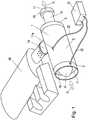
- Figure 1 shows a preferred embodiment of a device for performing the method, according to the present invention, to optimise the combustion in a combustion technology.
- FIG. 1 shows an oxygen enriching device 1, according to the invention, which is connected by an adaptor 19 to a combustion device 20.
- Ambient air shown as arrow A, is introduced into the oxygen enriching device 1.
- Oxygen enriching device 1 is formed basically from casing 2 and enclosure 13. Enclosure 13 is provided with a sealing plug 8, located in proximity to air inlet 16. After enriching ambient air inside the chamber, enriched air is guided by adapter 19 into a combustion device 20. Waste air is guided into enclosure 13 by slots (not shown), located on the surface of enclosure 13. Waste air is released through waste air outlet 17 into the environment.
- a ventilator 15 is provided to remove waste air from the enclosure 13, shown as arrow C.
- the process of oxygen enriching of ambient air requires a pulsed direct current electric field, which is provided by power supply 21. Electrodes (shown in Fig. 2 ) are located inside the chamber and are connected to power supply 21 by electrical connections 22.
- the device in form of means for guiding combustion air, comprises an oxygen enriching device 1.
- the oxygen enriching device 1 comprises a chamber comprising at least two sections.
- the first section serves for the introduction of ambient air and serves for the separation of the components of the introduced ambient air.
- the first section is mainly, and/or at least in parts, formed by casing 2.
- the second section of the chamber serves for discharging waste air into the environment.
- the second section is mainly, and/or at least in parts, formed by enclosure 13. Furthermore, parts of enclosure 13 may form the negatively charged electrode 4.
- enclosure 13 and negatively charged electrode 4 may be used as synonyms.
- the first section of the chamber comprises an air inlet 16 and an enriched air outlet 18, and the second section of the chamber comprises at least a waste air outlet 17.
- the casing 2 is made of a material that is electrically conductive. Inside the casing 2, at least two electrodes 3, 4 are arranged. At least one electrode 3 is positively charged and at least one electrode 4 is negatively charged. Both electrodes 3, 4 are arranged coaxially to oxygen enriching device 1. Further, the positively charged electrode 3 encloses the negatively charged electrode 4, whereas both electrodes 3, 4 are not in direct contact with each other, leaving at least a flow gap 10 in between them.
- an air humidifying device (not shown) or air moisturizing device (not shown) may be arranged in close proximity to air inlet 16.
- the air moisturizing device is arranged in flow direction A (arrow A) so that ambient air is moistened, which facilitates further ionization of ambient air in oxygen enriching device 1.
- casing 2 and the enclosure 13 are presented in form of pipes, however, it is to be understood that any kind of body of revolution can be used for casing 2 and enclosure 13, depending on the application to which the device of the present invention is used.
- the casing 2 in this embodiment is made of any material which may be electrically conductive, such as metals, carbon fibres or composite materials thereof.
- casing 2 is made from aluminium and is EMC-safe on the outside. Inside of casing 2, especially at least in the region of positively charged electrode 3, isolation material 12 is positioned.
- casing 2 and enclosure 13 are coaxially arranged, wherein enclosure 13 in placed inside of casing 2.
- Centring collars 9, 9a are provided, in order to maintain enclosure 13 centred inside casing 2.
- Centring collar 9 holds enclosure 13 in close proximity to air inlet 16 and centring collar 9a holds enclosure 13 in close proximity to waste air outlet 17.
- enclosure 13 comprises a plug 8 on the side that is directed to air inlet 16.
- Plug 9 may advantageously be in form of a paraboloid of revolution, and the like, in order to minimize flow resistance of incoming air.
- the other side of enclosure 13 is left open und this open side extends out of casing 2, thereby forming waste air outlet 17.
- casing 2 is open in direction to air inlet 16 so that ambient air can flow into casing 2.
- plug 8a is provided in order to close casing 2.
- Plug 8a is formed in order to allow enclosure 13 to extend through plug 8a.
- a ventilator 15 may be arranged in close proximity to sealing plug 8a or may be connected to the sealing plug 8a in order to accelerate the air flow velocity in direction of arrow C.
- plug 8a and centring collar 9a may be combined with each other, in order to simplify manufacture of the device according to the invention.
- centring collar 9a may also form enriched air outlet 18, leading to adapter 19, for example.
- enclosure 13 may serve as negatively charged electrode 4, also called cathode 4.
- electrical connection 11 is provided.
- centring collar 9 may be used in order to attach electrical connection 11 to cathode 4.
- centring collar 9a may also be used to attach an electrical connection, if required.
- parts of enclosure 13, that serve as cathode 4 must provide an electrical conductivity.
- cathode 4 extends to a region that is limited by centring collar 9 on one side and centring collar 9a on the other side.
- spiral guiding surfaces 5 are arranged, which preferably have at least the following two important functions: On the one hand, the spiral guiding surfaces 5 are important for converting the ambient airflow that is introduced into the first section of the chamber from a translational movement into a rotational movement. The conversion is advantageous in order to accelerate the motion of the molecules of the gas. Further, a stratification of the air or gas molecules is caused by the Ranque-Hilsch effect, which supports the separation of nitrogen.
- spiral guiding surfaces 5 are also important for conductance of the applied voltage.
- the conductivity of guiding surfaces 5 has to be adjusted according to the intended use of the device according to the invention.
- the positively charged electrode 3 is isolated from the casing 2 by an isolation material 12.
- the isolation material 12 is important in order to avoid a short circuit in embodiments where the casing 2 is made of conductive material as well.
- At least one guide rail 5 On the surface of the enclosure 13, preferably in the region of the negatively charged electrode 4, is at least one guide rail 5 arranged forming spiral guiding surfaces 5.
- a high voltage wire is arranged on the edges 6 of the at least one guide rail 5.
- the edges 6 may be covered with or made out of a conductive material such as carbon fibres, fibre brushes and the like. The applied voltage is conducted by the high voltage wire, which is positioned in between the positively charged electrode 3 and the negatively charged electrode 4.
- the edges 6 may be made from a material that must not be conductive but appropriate to emit electrons in an appropriate quantity and velocity, so that the demands of the combustion device are met.
- a pulsed direct current electric field is produced due to the different potential between the two electrodes 3, 4, which is used as ionization energy.
- the chosen frequency of the pulsed direct current electric field causes a resonance in the form of vibration, which leads to an ionisation of ionisable components of the introduced ambient air.
- Ionisable components are chosen from oxygen containing components, such as oxygen, water, carbon monoxide, carbon dioxide, formaldehyde and/or acids, whereas nitrogen is non-ionisable.
- the pulsed direct current electric field accelerates the negatively charged ions.
- the negatively charged oxygen containing components change their trajectory away from the centre of the negatively charged electrode 4 to the positively charged electrode 3, caused by the ionisation of the introduced ambient air flow.
- the non-ionised components such as nitrogen keep their trajectory in a straight manner in the centre of the negatively charged electrode 4.
- the airflow that mostly contains non-ionised nitrogen is discharged trough at least one slot 7, which is arranged on the surface of the enclosure 13, out of the second section of the chamber (in a direction of arrow C) of the device into the environment.
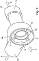
- FIG 3 the embodiment of a part of the chamber with the air outlet plug attachable to the combustion device is shown. It is shown that part of casing 2 forms an adapter 19 that directs enriched air through enriched air outlet 18 to combustion device 20.
- Ambient air having a flow direction indicated with arrow A, is directed into oxygen enriching device 1.
- Casing 2 is closed with sealing plug 8a, sealing plug 8a being arranged opposite to air inlet 16 (shown in figure 2 ), so that air flow of oxygen enriched air is guided through enriched air outlet 18 into adapter 19.
- This airflow is indicated with arrow B.
- Non-ionized components have entered enclosure 13 through slots 7 (as shown in figure 2 ) and form waste air that is discharged from oxygen enriching device 1 though waste air outlet 17.
- the waste air has a flow direction indicated with arrow C. Discharging of waste air may be optimized using a ventilator 15, the ventilator being arranged in close proximity to waste air outlet 17.
- adapter 19 may be in form of fastening means that clasp around casing 2.
- Enriched air outlet 18 forms a blow-out opening into the combustion chamber 20.
- magnets such as electric or permanent magnets, may be arranged outside the oxygen enriching device 1, which produce a magnetic field inside the oxygen enriching device 1, especially in the first section of the chamber where the ionisation of the introduced ambient air occurs.
- the magnetic field can also be produced by a pulsed inductor instead of magnets arranged outside the oxygen enriching device 1.
- the trajectory of the negatively charged oxygen containing components is further curved towards the positively charged electrode 3 due to the influence of the magnetic field.
- the magnetic field has no influence on nitrogen or nitrogen containing compounds.
- the magnetic field applied may be in the range of 0.1 T - 10T.
- the magnetic field is also required for moving the oxygen containing components away from the catalytic layer 14b (shown in Fig. 4 ). Therefore, the use of a magnetic field leads to a more efficient reactivation of the catalytic layer 14b and to a further movement of the oxygen containing components into the combustion.
- Figure 4 is a schematic representation of a first alternative embodiment of an electrode assembly comprising the positively charged electrode 3 of figure 2 .
- the electrode assembly comprises five structures, which are preferably stacked directly upon one another, the order of the structures being the following: casing 2, isolation material 12, electrode 3, barrier layer 14a and catalytic layer 14b.
- the first structure of assembly is the casing 2, which is the surrounding layer of the device of the present invention.
- the outer surface of the casing 2 is therefore in contact with the environment.
- the casing 2 is a body of revolution, whereas the exact form depends on the use of the device, according to the present invention. Further, the casing 2 has an isolating function for the device of the present invention towards the environment.
- the positively charged electrode 3 with its required electric connections 11a is carried by the casing 2.
- the casing 2 is suitable for temperatures up to 600°C and has a thickness between preferably 0.5 - 3 mm. In this embodiment the casing may consist of a material that is conductive.
- the second structure is an isolation material 12 which is arranged between the casing 2 and the positively charged electrode 3.
- This isolation material 12 is required when the casing 2 consists of a material that is conductive in order to avoid any short circuit due to the electric conductivity that would occur between the casing 2 and the positively charged electrode 3 without any isolation material 12. Further the isolation material 12 is required in order to shield the high voltage.
- the third structure in this embodiment is the positively charged electrode 3.
- the positively charged electrode 3 consists of a very thin good electrically conductive material, such as copper.
- the positively charged electrode 3 may also be used as casing 2 as well. In such embodiments an isolating layer would be required to be applied on the outer surface of the positively charged electrode 3.
- the fourth structure shown in figure 4 is the barrier layer 14a.
- the barrier layer 14a is preferably made of aluminium oxide and has a preferred thickness of approximately 100 ⁇ m.
- the barrier layer 14a has two important functions. The first function is to isolate the positive pole in order to enable the electric field.
- the disruptive voltage is in the range of approximately 5 kV to 100 kV, preferably 30 kV to 80 kV.
- the barrier layer 14a is the carrier for the catalytic layer 14b.
- the fifth structure of the embodiment shown in figure 4 is the catalytic layer 14b, which consists of two parts.
- the first part serves as a resonance layer for the second part of the catalytic layer 14b, which is the activating part of the catalytic layer 14b.
- the first part of the catalytic layer 14b is made of 4 to 6 layers that might consist of silicon dioxide and has a total thickness of 50 ⁇ m. Those first layers of the first part of the catalytic layer 14b have very strong piezoelectric properties with a positively charged dipole that is directed to the negatively charged electrode (not shown).
- Fine particles are added to the final layer of the first part of the catalytic layer 14b in order to increase the surface and to create islets of electrons as highly reactive centres. This leads to a reduced flow resistance and accelerates the negatively charged components towards the combustion chamber.
- the fine particles used according to the invention may be selected from ferro electrical and/or piezo electrical nano particles.
- the second part of the catalytic layer 14b is the finishing layer which is a very thin layer of approximately 25 nm thickness.
- the finishing layer is procedurally applied as an undulated thin film.
- the finishing layer functions as an activating layer of the catalytic layer 14b which enables water molecules and carbon dioxide to be broken down into their active atoms at ambient temperature.
- the catalytic layer 14b is also required for hydrolysis and for energising oxygen and its radicals.
- the electrode assembly consists of four structures, which are preferably stacked directly upon one other, the order of the structures being the following: casing 2, electrode 3, barrier layer 14a and catalytic layer 14b.
- the embodiment of figure 5 has no layer consisting of isolation material 12. Therefore, in this embodiment, casing 2 has to consist of material that is electrically insulating, such as plastic material. Otherwise, if casing 2 and the positively charged electrode 3 both consist of material that is electroconductive a short circuit might occur, as no isolation material is arranged between the casing 2 and positively charged electrode 3. Besides this difference, the correlating structures of this embodiment have the same composition and functions described for the structures in figure 4 .
- electrons are present in excess and preferably ionise the oxygen of the ambient air preferably into dianions. Further, the electrons are distributed on the surface of the catalytic layer 14a of the positively charged electrode 3, causing silent discharges which form a cold highly reactive plasma.
- the formed plasma is pushed into the direction of the combustion chamber by the piezoelectric impulse caused by the catalytic layer and/or the optional magnetic field. The aggressiveness of the plasma towards the combustible molecules leads to a dramatically enhanced combustion.
- the dipoles of the piezoelectric layer in the catalytic layer are continuously changed due to the high voltage impulses applied. This causes attraction and repel of electrons, anions, dipoles, reactants and products, which forms a negatively charged plasma gas.
- the velocity of the plasma gas is increased due to the electron emission, the flow, the piezoelectric impulse and the pulsed magnetic field.
- Test A 2002 Model Year Volkswagen Jetta TDI 4 Cylinder Diesel engine was used. The test was performed according to Highway Fuel Economy Test (HWFET). Table 1 shows the results of the test. Test A and B have been performed as baseline test. Tests 1 to 6 have been performed using a device according to the embodiment as described in figures 2 and 3 .
- HWFET Highway Fuel Economy Test
- the fuel consumption has been reduced about 5 % and the amount of NOx gases has been reduced by > 5 %.
Landscapes
- Engineering & Computer Science (AREA)
- Chemical & Material Sciences (AREA)
- Combustion & Propulsion (AREA)
- Mechanical Engineering (AREA)
- General Engineering & Computer Science (AREA)
- Chemical Kinetics & Catalysis (AREA)
- Analytical Chemistry (AREA)
- General Chemical & Material Sciences (AREA)
- Oil, Petroleum & Natural Gas (AREA)
- Physical Or Chemical Processes And Apparatus (AREA)
Applications Claiming Priority (3)
| Application Number | Priority Date | Filing Date | Title |
|---|---|---|---|
| EP15165979 | 2015-04-30 | ||
| US201562201282P | 2015-08-05 | 2015-08-05 | |
| PCT/EP2016/059802 WO2016174274A1 (en) | 2015-04-30 | 2016-05-02 | Method for optimising combustion in combustion devices and device for performing the method |
Publications (2)
| Publication Number | Publication Date |
|---|---|
| EP3289211A1 EP3289211A1 (en) | 2018-03-07 |
| EP3289211B1 true EP3289211B1 (en) | 2021-04-07 |
Family
ID=53039766
Family Applications (1)
| Application Number | Title | Priority Date | Filing Date |
|---|---|---|---|
| EP16724855.8A Active EP3289211B1 (en) | 2015-04-30 | 2016-05-02 | Method for optimising combustion in combustion devices and device for performing the method |
Country Status (5)
| Country | Link |
|---|---|
| US (1) | US10436166B2 (https=) |
| EP (1) | EP3289211B1 (https=) |
| JP (1) | JP6771022B2 (https=) |
| CN (1) | CN107690524B (https=) |
| WO (1) | WO2016174274A1 (https=) |
Families Citing this family (1)
| Publication number | Priority date | Publication date | Assignee | Title |
|---|---|---|---|---|
| RU201062U1 (ru) * | 2020-02-06 | 2020-11-25 | Федеральное государственное бюджетное образовательное учреждение высшего образования "Самарский государственный университет путей сообщения" (СамГУПС) | Система для обработки топлива и воздуха в двигателе внутреннего сгорания |
Family Cites Families (28)
| Publication number | Priority date | Publication date | Assignee | Title |
|---|---|---|---|---|
| DE2246891A1 (de) * | 1972-09-23 | 1974-04-04 | Fritz Maus | Verfahren und aggregat zur anreicherung der verbrennungsluft mit luftsauerstoff |
| NL7303156A (https=) | 1973-03-06 | 1974-09-10 | ||
| US3943407A (en) * | 1973-08-01 | 1976-03-09 | Scientific Enterprises, Inc. | Method and apparatus for producing increased quantities of ions and higher energy ions |
| DE2551075A1 (de) | 1974-11-20 | 1976-08-12 | Amfin Corp | Anordnung zum ionisieren des einlassystems einer brennkraftmaschine |
| GB1525600A (en) * | 1974-12-20 | 1978-09-20 | Nippon Soken | Internal combustion engines with a methanol reforming system |
| JPS5348232A (en) * | 1976-10-13 | 1978-05-01 | Michiaki Adachi | Combustion apparatus that use ozone cenerating unit at the same time |
| DE3021661A1 (de) | 1980-04-09 | 1981-12-17 | Gottfried 6486 Brachttal Bähr | Verfahren und vorrichtung einer mittels dauermagnetsystem konstant verdichtende und durch mehr oder minder stromdurchflossener spule oder spulen steuerbare zusatzverdichtende sauerstoffanreicherung |
| US4911894A (en) * | 1987-07-22 | 1990-03-27 | William B. Retallick | Catalytic air cleaner |
| US5010869A (en) * | 1989-08-11 | 1991-04-30 | Zenion Industries, Inc. | Air ionization system for internal combustion engines |
| JPH04305226A (ja) | 1991-01-25 | 1992-10-28 | Senichi Masuda | ガス中窒素酸化物の低減方法 |
| TW241325B (en) * | 1992-12-15 | 1995-02-21 | Huei-Shyi Chen | A device for increasing combustion efficiency of engine |
| CN1155623A (zh) | 1996-02-15 | 1997-07-30 | 宋永海 | 燃料气化裂解催化器 |
| WO1997044581A1 (en) * | 1996-12-09 | 1997-11-27 | Hideaki Watase | Combustion enhancing apparatus |
| US5942026A (en) * | 1997-10-20 | 1999-08-24 | Erlichman; Alexander | Ozone generators useful in automobiles |
| CA2325072A1 (en) * | 2000-10-30 | 2002-04-30 | Questair Technologies Inc. | Gas separation for molten carbonate fuel cell |
| DE10132582C1 (de) | 2001-07-10 | 2002-08-08 | Karlsruhe Forschzent | Anlage zum elektrostatischen Reinigen von Gas und Verfahren zum Betreiben derselben |
| US6895945B2 (en) * | 2002-07-12 | 2005-05-24 | Parsa Investments, L.P. | System and method for conditioning of intake air for an internal combustion engine |
| HUP0302008A2 (hu) * | 2003-06-30 | 2005-07-28 | Péter Rozim | Emissziót és tüzelőanyag-fogyasztást csökkentő eljárás és berendezés belső égésű motorban zajló égés tökéletesebbé tételére |
| US7490467B2 (en) * | 2004-06-15 | 2009-02-17 | Cummings Craig D | Gas flow enhancer for combustion engines |
| CN100445547C (zh) * | 2006-01-12 | 2008-12-24 | 重庆瑞卡科技有限公司 | 机动车发动机进气激化装置 |
| KR20090078904A (ko) * | 2008-01-16 | 2009-07-21 | (주)세기오토테크놀로지 | 조연성 증대를 위한 산소활성화 장치가 호스와 일체가 된자동차 흡기호스 |
| WO2010096087A1 (en) * | 2008-08-19 | 2010-08-26 | Sonic Blue Aerospace, Inc. | Magnetic advanced generation jet electric turbine |
| US8564924B1 (en) * | 2008-10-14 | 2013-10-22 | Global Plasma Solutions, Llc | Systems and methods of air treatment using bipolar ionization |
| CN102080613A (zh) * | 2009-11-27 | 2011-06-01 | 北京中科环美科技有限公司 | 一种燃油分子电离方法及装置 |
| US20110174277A1 (en) * | 2010-01-20 | 2011-07-21 | Bert Socolove | Universal hydrogen plasma carburetor |
| CN102614749B (zh) * | 2011-01-26 | 2014-10-22 | 北京星旋世纪科技有限公司 | 涡旋式冷热气体分离装置 |
| DE102011011819A1 (de) * | 2011-02-19 | 2012-08-23 | Mark Steyn | Vorrichtung zur Vergrößerung der Sauerstoffmenge im Luftgemisch, zugeführt in Brennkraftmaschine |
| RU2464441C1 (ru) * | 2011-08-09 | 2012-10-20 | ООО "Центр инновационных технологий" | Ионизатор воздуха для двигателя внутреннего сгорания |
-
2016
- 2016-05-02 US US15/570,480 patent/US10436166B2/en not_active Expired - Fee Related
- 2016-05-02 WO PCT/EP2016/059802 patent/WO2016174274A1/en not_active Ceased
- 2016-05-02 CN CN201680033167.5A patent/CN107690524B/zh not_active Expired - Fee Related
- 2016-05-02 EP EP16724855.8A patent/EP3289211B1/en active Active
- 2016-05-02 JP JP2018507778A patent/JP6771022B2/ja not_active Expired - Fee Related
Non-Patent Citations (1)
| Title |
|---|
| None * |
Also Published As
| Publication number | Publication date |
|---|---|
| WO2016174274A1 (en) | 2016-11-03 |
| EP3289211A1 (en) | 2018-03-07 |
| US20180142661A1 (en) | 2018-05-24 |
| JP2018515718A (ja) | 2018-06-14 |
| CN107690524B (zh) | 2020-05-19 |
| JP6771022B2 (ja) | 2020-10-21 |
| CN107690524A (zh) | 2018-02-13 |
| US10436166B2 (en) | 2019-10-08 |
Similar Documents
| Publication | Publication Date | Title |
|---|---|---|
| CN101279715B (zh) | 利用非平衡等离子体消除挥发性有机物同时制氢的装置 | |
| CN103945628B (zh) | 定向自旋等离子体激励器及定向自旋流动控制方法 | |
| CN104128077B (zh) | 一种双层套筒式电晕等离子体发生装置 | |
| CN107051198A (zh) | 阵列式等离子体‑催化剂协同作用的废气处理装置 | |
| CN1749662A (zh) | 表面放电型空气净化装置 | |
| CN101158321A (zh) | 一种低温等离子体非热点火稳焰装置 | |
| CN108722700B (zh) | 一种活性炭粉末荷电离散喷射装置 | |
| CN113304584B (zh) | 一种自电再生式磁旋分选等离子体净化焦化尾废气系统 | |
| EP3289211B1 (en) | Method for optimising combustion in combustion devices and device for performing the method | |
| US20230332564A1 (en) | Intake plasma generator systems and methods | |
| CN108246058A (zh) | 一种水泥窑协同处置飞灰窑前脱除汞和二噁英的净化装置 | |
| RU2492394C2 (ru) | Устройство для вентиляции воздуха | |
| CN203884064U (zh) | 定向自旋等离子体激励器 | |
| RU2708218C2 (ru) | Способ оптимизации горения в устройствах для сжигания топлива и устройство для выполнения способа | |
| WO2008091519A1 (en) | Device for remediation of gaseous and aerosol streams | |
| CN203108410U (zh) | 非均匀场强等离子体废气处理装置及处理系统 | |
| RU2313732C2 (ru) | Способ увеличения скорости электрического ветра и устройство для его осуществления | |
| RU199195U1 (ru) | Плазменный нейтрализатор токсичных газов | |
| CN110000003B (zh) | 一种基于空心针电极的喷头式负离子发射枪 | |
| KR20090078904A (ko) | 조연성 증대를 위한 산소활성화 장치가 호스와 일체가 된자동차 흡기호스 | |
| CN209715396U (zh) | 一种基于空心针电极的喷头式负离子发射枪 | |
| CN104796038A (zh) | 一种荷电团簇迁移的动能-电能转换装置 | |
| CN209715404U (zh) | 一种基于实心针电极的喷头式负离子发射枪 | |
| CN1812686A (zh) | 基于缩放通道结构的大气压放电冷等离子体发生器及阵列 | |
| CN200976707Y (zh) | 基于缩放通道结构的大气压放电冷等离子体发生器及阵列 |
Legal Events
| Date | Code | Title | Description |
|---|---|---|---|
| STAA | Information on the status of an ep patent application or granted ep patent |
Free format text: STATUS: THE INTERNATIONAL PUBLICATION HAS BEEN MADE |
|
| PUAI | Public reference made under article 153(3) epc to a published international application that has entered the european phase |
Free format text: ORIGINAL CODE: 0009012 |
|
| STAA | Information on the status of an ep patent application or granted ep patent |
Free format text: STATUS: REQUEST FOR EXAMINATION WAS MADE |
|
| 17P | Request for examination filed |
Effective date: 20171129 |
|
| AK | Designated contracting states |
Kind code of ref document: A1 Designated state(s): AL AT BE BG CH CY CZ DE DK EE ES FI FR GB GR HR HU IE IS IT LI LT LU LV MC MK MT NL NO PL PT RO RS SE SI SK SM TR |
|
| AX | Request for extension of the european patent |
Extension state: BA ME |
|
| DAV | Request for validation of the european patent (deleted) | ||
| DAX | Request for extension of the european patent (deleted) | ||
| STAA | Information on the status of an ep patent application or granted ep patent |
Free format text: STATUS: EXAMINATION IS IN PROGRESS |
|
| 17Q | First examination report despatched |
Effective date: 20181116 |
|
| REG | Reference to a national code |
Ref country code: DE Ref legal event code: R079 Ref document number: 602016055619 Country of ref document: DE Free format text: PREVIOUS MAIN CLASS: F02M0027000000 Ipc: F02N0011080000 |
|
| GRAP | Despatch of communication of intention to grant a patent |
Free format text: ORIGINAL CODE: EPIDOSNIGR1 |
|
| STAA | Information on the status of an ep patent application or granted ep patent |
Free format text: STATUS: GRANT OF PATENT IS INTENDED |
|
| RIC1 | Information provided on ipc code assigned before grant |
Ipc: F02M 27/02 20060101ALI20200918BHEP Ipc: F02N 11/08 20060101AFI20200918BHEP Ipc: F02M 27/04 20060101ALI20200918BHEP |
|
| INTG | Intention to grant announced |
Effective date: 20201028 |
|
| GRAS | Grant fee paid |
Free format text: ORIGINAL CODE: EPIDOSNIGR3 |
|
| GRAA | (expected) grant |
Free format text: ORIGINAL CODE: 0009210 |
|
| STAA | Information on the status of an ep patent application or granted ep patent |
Free format text: STATUS: THE PATENT HAS BEEN GRANTED |
|
| AK | Designated contracting states |
Kind code of ref document: B1 Designated state(s): AL AT BE BG CH CY CZ DE DK EE ES FI FR GB GR HR HU IE IS IT LI LT LU LV MC MK MT NL NO PL PT RO RS SE SI SK SM TR |
|
| REG | Reference to a national code |
Ref country code: GB Ref legal event code: FG4D |
|
| REG | Reference to a national code |
Ref country code: AT Ref legal event code: REF Ref document number: 1380001 Country of ref document: AT Kind code of ref document: T Effective date: 20210415 Ref country code: CH Ref legal event code: EP |
|
| REG | Reference to a national code |
Ref country code: DE Ref legal event code: R096 Ref document number: 602016055619 Country of ref document: DE |
|
| REG | Reference to a national code |
Ref country code: IE Ref legal event code: FG4D |
|
| REG | Reference to a national code |
Ref country code: LT Ref legal event code: MG9D |
|
| PGFP | Annual fee paid to national office [announced via postgrant information from national office to epo] |
Ref country code: DE Payment date: 20210618 Year of fee payment: 6 |
|
| PGFP | Annual fee paid to national office [announced via postgrant information from national office to epo] |
Ref country code: GB Payment date: 20210618 Year of fee payment: 6 |
|
| REG | Reference to a national code |
Ref country code: NL Ref legal event code: MP Effective date: 20210407 Ref country code: AT Ref legal event code: MK05 Ref document number: 1380001 Country of ref document: AT Kind code of ref document: T Effective date: 20210407 |
|
| PG25 | Lapsed in a contracting state [announced via postgrant information from national office to epo] |
Ref country code: HR Free format text: LAPSE BECAUSE OF FAILURE TO SUBMIT A TRANSLATION OF THE DESCRIPTION OR TO PAY THE FEE WITHIN THE PRESCRIBED TIME-LIMIT Effective date: 20210407 Ref country code: BG Free format text: LAPSE BECAUSE OF FAILURE TO SUBMIT A TRANSLATION OF THE DESCRIPTION OR TO PAY THE FEE WITHIN THE PRESCRIBED TIME-LIMIT Effective date: 20210707 Ref country code: AT Free format text: LAPSE BECAUSE OF FAILURE TO SUBMIT A TRANSLATION OF THE DESCRIPTION OR TO PAY THE FEE WITHIN THE PRESCRIBED TIME-LIMIT Effective date: 20210407 Ref country code: NL Free format text: LAPSE BECAUSE OF FAILURE TO SUBMIT A TRANSLATION OF THE DESCRIPTION OR TO PAY THE FEE WITHIN THE PRESCRIBED TIME-LIMIT Effective date: 20210407 Ref country code: LT Free format text: LAPSE BECAUSE OF FAILURE TO SUBMIT A TRANSLATION OF THE DESCRIPTION OR TO PAY THE FEE WITHIN THE PRESCRIBED TIME-LIMIT Effective date: 20210407 Ref country code: FI Free format text: LAPSE BECAUSE OF FAILURE TO SUBMIT A TRANSLATION OF THE DESCRIPTION OR TO PAY THE FEE WITHIN THE PRESCRIBED TIME-LIMIT Effective date: 20210407 |
|
| PG25 | Lapsed in a contracting state [announced via postgrant information from national office to epo] |
Ref country code: GR Free format text: LAPSE BECAUSE OF FAILURE TO SUBMIT A TRANSLATION OF THE DESCRIPTION OR TO PAY THE FEE WITHIN THE PRESCRIBED TIME-LIMIT Effective date: 20210708 Ref country code: IS Free format text: LAPSE BECAUSE OF FAILURE TO SUBMIT A TRANSLATION OF THE DESCRIPTION OR TO PAY THE FEE WITHIN THE PRESCRIBED TIME-LIMIT Effective date: 20210807 Ref country code: LV Free format text: LAPSE BECAUSE OF FAILURE TO SUBMIT A TRANSLATION OF THE DESCRIPTION OR TO PAY THE FEE WITHIN THE PRESCRIBED TIME-LIMIT Effective date: 20210407 Ref country code: SE Free format text: LAPSE BECAUSE OF FAILURE TO SUBMIT A TRANSLATION OF THE DESCRIPTION OR TO PAY THE FEE WITHIN THE PRESCRIBED TIME-LIMIT Effective date: 20210407 Ref country code: RS Free format text: LAPSE BECAUSE OF FAILURE TO SUBMIT A TRANSLATION OF THE DESCRIPTION OR TO PAY THE FEE WITHIN THE PRESCRIBED TIME-LIMIT Effective date: 20210407 Ref country code: NO Free format text: LAPSE BECAUSE OF FAILURE TO SUBMIT A TRANSLATION OF THE DESCRIPTION OR TO PAY THE FEE WITHIN THE PRESCRIBED TIME-LIMIT Effective date: 20210707 Ref country code: PT Free format text: LAPSE BECAUSE OF FAILURE TO SUBMIT A TRANSLATION OF THE DESCRIPTION OR TO PAY THE FEE WITHIN THE PRESCRIBED TIME-LIMIT Effective date: 20210809 Ref country code: PL Free format text: LAPSE BECAUSE OF FAILURE TO SUBMIT A TRANSLATION OF THE DESCRIPTION OR TO PAY THE FEE WITHIN THE PRESCRIBED TIME-LIMIT Effective date: 20210407 |
|
| REG | Reference to a national code |
Ref country code: CH Ref legal event code: PL |
|
| REG | Reference to a national code |
Ref country code: DE Ref legal event code: R097 Ref document number: 602016055619 Country of ref document: DE |
|
| PG25 | Lapsed in a contracting state [announced via postgrant information from national office to epo] |
Ref country code: EE Free format text: LAPSE BECAUSE OF FAILURE TO SUBMIT A TRANSLATION OF THE DESCRIPTION OR TO PAY THE FEE WITHIN THE PRESCRIBED TIME-LIMIT Effective date: 20210407 Ref country code: CZ Free format text: LAPSE BECAUSE OF FAILURE TO SUBMIT A TRANSLATION OF THE DESCRIPTION OR TO PAY THE FEE WITHIN THE PRESCRIBED TIME-LIMIT Effective date: 20210407 Ref country code: DK Free format text: LAPSE BECAUSE OF FAILURE TO SUBMIT A TRANSLATION OF THE DESCRIPTION OR TO PAY THE FEE WITHIN THE PRESCRIBED TIME-LIMIT Effective date: 20210407 Ref country code: SK Free format text: LAPSE BECAUSE OF FAILURE TO SUBMIT A TRANSLATION OF THE DESCRIPTION OR TO PAY THE FEE WITHIN THE PRESCRIBED TIME-LIMIT Effective date: 20210407 Ref country code: SM Free format text: LAPSE BECAUSE OF FAILURE TO SUBMIT A TRANSLATION OF THE DESCRIPTION OR TO PAY THE FEE WITHIN THE PRESCRIBED TIME-LIMIT Effective date: 20210407 Ref country code: LU Free format text: LAPSE BECAUSE OF NON-PAYMENT OF DUE FEES Effective date: 20210502 Ref country code: LI Free format text: LAPSE BECAUSE OF NON-PAYMENT OF DUE FEES Effective date: 20210531 Ref country code: MC Free format text: LAPSE BECAUSE OF FAILURE TO SUBMIT A TRANSLATION OF THE DESCRIPTION OR TO PAY THE FEE WITHIN THE PRESCRIBED TIME-LIMIT Effective date: 20210407 Ref country code: CH Free format text: LAPSE BECAUSE OF NON-PAYMENT OF DUE FEES Effective date: 20210531 Ref country code: RO Free format text: LAPSE BECAUSE OF FAILURE TO SUBMIT A TRANSLATION OF THE DESCRIPTION OR TO PAY THE FEE WITHIN THE PRESCRIBED TIME-LIMIT Effective date: 20210407 Ref country code: ES Free format text: LAPSE BECAUSE OF FAILURE TO SUBMIT A TRANSLATION OF THE DESCRIPTION OR TO PAY THE FEE WITHIN THE PRESCRIBED TIME-LIMIT Effective date: 20210407 |
|
| REG | Reference to a national code |
Ref country code: BE Ref legal event code: MM Effective date: 20210531 |
|
| PLBE | No opposition filed within time limit |
Free format text: ORIGINAL CODE: 0009261 |
|
| STAA | Information on the status of an ep patent application or granted ep patent |
Free format text: STATUS: NO OPPOSITION FILED WITHIN TIME LIMIT |
|
| 26N | No opposition filed |
Effective date: 20220110 |
|
| PG25 | Lapsed in a contracting state [announced via postgrant information from national office to epo] |
Ref country code: IE Free format text: LAPSE BECAUSE OF NON-PAYMENT OF DUE FEES Effective date: 20210502 |
|
| PG25 | Lapsed in a contracting state [announced via postgrant information from national office to epo] |
Ref country code: IS Free format text: LAPSE BECAUSE OF FAILURE TO SUBMIT A TRANSLATION OF THE DESCRIPTION OR TO PAY THE FEE WITHIN THE PRESCRIBED TIME-LIMIT Effective date: 20210807 Ref country code: FR Free format text: LAPSE BECAUSE OF NON-PAYMENT OF DUE FEES Effective date: 20210607 Ref country code: AL Free format text: LAPSE BECAUSE OF FAILURE TO SUBMIT A TRANSLATION OF THE DESCRIPTION OR TO PAY THE FEE WITHIN THE PRESCRIBED TIME-LIMIT Effective date: 20210407 |
|
| PG25 | Lapsed in a contracting state [announced via postgrant information from national office to epo] |
Ref country code: IT Free format text: LAPSE BECAUSE OF FAILURE TO SUBMIT A TRANSLATION OF THE DESCRIPTION OR TO PAY THE FEE WITHIN THE PRESCRIBED TIME-LIMIT Effective date: 20210407 Ref country code: BE Free format text: LAPSE BECAUSE OF NON-PAYMENT OF DUE FEES Effective date: 20210531 |
|
| REG | Reference to a national code |
Ref country code: DE Ref legal event code: R119 Ref document number: 602016055619 Country of ref document: DE |
|
| GBPC | Gb: european patent ceased through non-payment of renewal fee |
Effective date: 20220502 |
|
| PG25 | Lapsed in a contracting state [announced via postgrant information from national office to epo] |
Ref country code: HU Free format text: LAPSE BECAUSE OF FAILURE TO SUBMIT A TRANSLATION OF THE DESCRIPTION OR TO PAY THE FEE WITHIN THE PRESCRIBED TIME-LIMIT; INVALID AB INITIO Effective date: 20160502 Ref country code: GB Free format text: LAPSE BECAUSE OF NON-PAYMENT OF DUE FEES Effective date: 20220502 Ref country code: DE Free format text: LAPSE BECAUSE OF NON-PAYMENT OF DUE FEES Effective date: 20221201 |
|
| PG25 | Lapsed in a contracting state [announced via postgrant information from national office to epo] |
Ref country code: CY Free format text: LAPSE BECAUSE OF FAILURE TO SUBMIT A TRANSLATION OF THE DESCRIPTION OR TO PAY THE FEE WITHIN THE PRESCRIBED TIME-LIMIT Effective date: 20210407 |
|
| PG25 | Lapsed in a contracting state [announced via postgrant information from national office to epo] |
Ref country code: MK Free format text: LAPSE BECAUSE OF FAILURE TO SUBMIT A TRANSLATION OF THE DESCRIPTION OR TO PAY THE FEE WITHIN THE PRESCRIBED TIME-LIMIT Effective date: 20210407 |
|
| PG25 | Lapsed in a contracting state [announced via postgrant information from national office to epo] |
Ref country code: MT Free format text: LAPSE BECAUSE OF FAILURE TO SUBMIT A TRANSLATION OF THE DESCRIPTION OR TO PAY THE FEE WITHIN THE PRESCRIBED TIME-LIMIT Effective date: 20210407 |
|
| PG25 | Lapsed in a contracting state [announced via postgrant information from national office to epo] |
Ref country code: TR Free format text: LAPSE BECAUSE OF FAILURE TO SUBMIT A TRANSLATION OF THE DESCRIPTION OR TO PAY THE FEE WITHIN THE PRESCRIBED TIME-LIMIT Effective date: 20210407 |