EP3288346A1 - Led-beleuchtungsvorrichtung - Google Patents
Led-beleuchtungsvorrichtung Download PDFInfo
- Publication number
- EP3288346A1 EP3288346A1 EP17192653.8A EP17192653A EP3288346A1 EP 3288346 A1 EP3288346 A1 EP 3288346A1 EP 17192653 A EP17192653 A EP 17192653A EP 3288346 A1 EP3288346 A1 EP 3288346A1
- Authority
- EP
- European Patent Office
- Prior art keywords
- led
- node
- triac dimmer
- bridge rectifier
- load
- Prior art date
- Legal status (The legal status is an assumption and is not a legal conclusion. Google has not performed a legal analysis and makes no representation as to the accuracy of the status listed.)
- Withdrawn
Links
Images


Classifications
-
- H—ELECTRICITY
- H05—ELECTRIC TECHNIQUES NOT OTHERWISE PROVIDED FOR
- H05B—ELECTRIC HEATING; ELECTRIC LIGHT SOURCES NOT OTHERWISE PROVIDED FOR; CIRCUIT ARRANGEMENTS FOR ELECTRIC LIGHT SOURCES, IN GENERAL
- H05B45/00—Circuit arrangements for operating light-emitting diodes [LED]
- H05B45/10—Controlling the intensity of the light
-
- H—ELECTRICITY
- H05—ELECTRIC TECHNIQUES NOT OTHERWISE PROVIDED FOR
- H05B—ELECTRIC HEATING; ELECTRIC LIGHT SOURCES NOT OTHERWISE PROVIDED FOR; CIRCUIT ARRANGEMENTS FOR ELECTRIC LIGHT SOURCES, IN GENERAL
- H05B45/00—Circuit arrangements for operating light-emitting diodes [LED]
- H05B45/30—Driver circuits
- H05B45/37—Converter circuits
-
- H—ELECTRICITY
- H05—ELECTRIC TECHNIQUES NOT OTHERWISE PROVIDED FOR
- H05B—ELECTRIC HEATING; ELECTRIC LIGHT SOURCES NOT OTHERWISE PROVIDED FOR; CIRCUIT ARRANGEMENTS FOR ELECTRIC LIGHT SOURCES, IN GENERAL
- H05B45/00—Circuit arrangements for operating light-emitting diodes [LED]
- H05B45/50—Circuit arrangements for operating light-emitting diodes [LED] responsive to malfunctions or undesirable behaviour of LEDs; responsive to LED life; Protective circuits
- H05B45/59—Circuit arrangements for operating light-emitting diodes [LED] responsive to malfunctions or undesirable behaviour of LEDs; responsive to LED life; Protective circuits for reducing or suppressing flicker or glow effects
-
- Y—GENERAL TAGGING OF NEW TECHNOLOGICAL DEVELOPMENTS; GENERAL TAGGING OF CROSS-SECTIONAL TECHNOLOGIES SPANNING OVER SEVERAL SECTIONS OF THE IPC; TECHNICAL SUBJECTS COVERED BY FORMER USPC CROSS-REFERENCE ART COLLECTIONS [XRACs] AND DIGESTS
- Y02—TECHNOLOGIES OR APPLICATIONS FOR MITIGATION OR ADAPTATION AGAINST CLIMATE CHANGE
- Y02B—CLIMATE CHANGE MITIGATION TECHNOLOGIES RELATED TO BUILDINGS, e.g. HOUSING, HOUSE APPLIANCES OR RELATED END-USER APPLICATIONS
- Y02B20/00—Energy efficient lighting technologies, e.g. halogen lamps or gas discharge lamps
- Y02B20/30—Semiconductor lamps, e.g. solid state lamps [SSL] light emitting diodes [LED] or organic LED [OLED]
Definitions
- the present invention relates to a light emitting diode (LED) lighting device and, more particularly, to a circuit configuration capable of preventing flickering due to the characteristics of a triode for alternating current (TRIAC) dimmer.
- LED light emitting diode
- TRIAC triode for alternating current
- Solid-state lighting (SSL) devices such as light emitting diode (LED) lighting devices attract much attention due to features such as low power consumption, long life and high luminance.
- LED light emitting diode
- One of the significant elements of a lighting device is a dimmer for controlling the brightness of light, and recently TRIAC-based dimmers are frequently used (See Korean Patent No. 1055865 ).
- the LED lighting device may flicker at a very low diming level or may even get permanently switched off. That is, when TRIAC dimmers are present, low power consumption of SSL devices may cause problems due to a latching and holding currents of the TRIAC dimmers.
- the minimum dimming level (MIN) includes a range in which a current flowing through a TRIAC dimmer drops below a holding current, and LED lighting device flickers in these periods.
- the present invention provides an electric circuit capable of preventing an operating current of a TRIAC dimmer from dropping below a holding current value.
- the present invention also provides an electric circuit capable of stabilizing an output voltage of a TRIAC dimmer.
- a light emitting diode (LED) lighting device including an LED; a bridge rectifier; a TRIAC dimmer for controlling the luminance of the LED; and a load connected between an output terminal of the TRIAC dimmer and the bridge rectifier to stabilize the operation of the TRIAC dimmer even in low dimming level of the TRIAC dimmer, wherein the bridge rectifier is connected with the load to supply an operating current to the LED and the LED receives the operating current from the bridge rectifier.
- the load may include a load resistor that is connected between a first node of the output terminal and a second node of the output terminal, and connected in parallel with the bridge rectifier.
- the load may include a first damping resistor that is connected between a first node of the output terminal and a first node of the bridge rectifier, and a second damping resistor that is connected between a second node of the output terminal and a second node of the bridge rectifier.
- the load may include a first damping resistor that is connected between a first node of the load resistor and a first node of the bridge rectifier, and a second damping resistor that is connected between a second node of the load resistor and a second node of the bridge rectifier.
- Each of the first and second damping resistors may include a plurality of resistors connected in parallel with each other.
- an operating current of a TRIAC dimmer may be prevented from dropping below a holding current value in the minimum dimming level of the dimmer, and thus flickering of a light emitting diode (LED) may be prevented.
- LED light emitting diode
- an output voltage of the TRIAC dimmer may be stabilized and thus operation of the LED may also be stabilized.
- FIG. 1 is a circuit diagram of a TRIAC dimmer.
- the basic elements of the TRIAC dimmer include a potentiometer R1, a fixed resister R2, a capacitor C1, a variable resistor W1, a diode for alternating current (DIAC) and a TRIAC.
- a resistor-capacitor (RC) network comprising R1, R2 and C1 delays the start-up of the TRIAC until the voltage of C1 reaches a trigger voltage of the DIAC.
- the start-up delay that reduces the on-time or "conduction angle" of the TRIAC, increases.
- the phase of the dimmer is controlled by W1 and C3, and the size of the conduction angle is controlled by a change of resistance of the variable resistor W1.
- the TRIAC When a current is applied to the gate of the TRIAC, the TRIAC is immediately turned on and thus an operating current I of the dimmer flows.
- the operating current I should not be dropped below a minimum holding current Ih to maintain the ON state of the TRIAC.
- the operating current I of the dimmer should always be maintained not less than the holding current Ih to maintain the operation of the TRIAC dimmer.
- the operating current I of the dimmer may be controlled by the load 10 that is applied to an output terminal of the dimmer.
- FIG. 2 is a block diagram of a light emitting diode (LED) lighting device according to an embodiment of the present invention.
- the LED lighting device comprising a TRIAC dimmer according an embodiment of to the present invention includes a TRIAC dimmer 100, a load 200, a bridge rectifier 300 and an LED 400.
- the TRIAC dimmer 100 controls the brightness of or dims light.
- the brightness of light may be controlled by changing the value of the resistance of the variable resistor W1 described above with reference to FIG. 1 .
- the load 200 is connected between an output terminal of the TRIAC dimmer 100 and the bridge rectifier 300. That is, the load 200 is connected between node A and node C, and between node B and node D.
- the circuit configuration of the load 200 will be described later with reference to FIG. 3 .
- the load 200 may stabilize the operation of the TRIAC dimmer 100 even in a low dimming level of the TRIAC dimmer 100.
- the reason why the load 200 can stabilize the operation of the TRIAC dimmer 100 even in a low dimming level of the TRIAC dimmer 100 will be described later with reference to FIG. 4 .
- the bridge rectifier 300 supplies a current to the LED 400.
- the bridge rectifier 300 receives an operating current from the TRIAC dimmer 100, rectifies the operating current, and supplies the rectified current to the LED 400.
- the LED 400 receives the current and emits light, and includes one or more LEDs.
- FIG. 3 is a circuit diagram of the load according to an embodiment of the present invention.
- the load 200 is connected between an output terminal (nodes A and B) of the TRIAC dimmer 100 and an input terminal (nodes C and D) of the bridge rectifier 300.
- the load 200 is connected in parallel with the bridge rectifier 300 and is connected with the output terminal (nodes A and B) of the TRIAC dimmer 100.
- the load 200 includes a load resistor 210 that is connected between a first node (node A) of the output terminal of the TRIAC dimmer 100 and a second node (node B) of the output terminal of the TRIAC dimmer 100, and is connected in parallel with the bridge rectifier 300.
- the bridge rectifier 300 and the LED 400 may be considered as loads having resistance. Accordingly, since the load resistor 210 is connected in parallel with the bridge rectifier 300 and the LED 400, the resistance of the output terminal of the TRIAC dimmer 100 becomes low.
- the load 200 may further include first damping resistors 221 and 222 and second damping resistors 231 and 232.
- the first damping resistors 221 and 222 are connected between the first node (node A) of the output terminal of the TRIAC dimmer 100 and a first node (node C) of the bridge rectifier 300
- the second damping resistors 231 and 232 are connected between the second node (node B) of the output terminal of the TRIAC dimmer 100 and a second node (node D) of the bridge rectifier 300.
- the first damping resistors 221 and 222 and second damping resistors 231 and 232 are configured to eliminate noise caused by overshoot or undershoot included in the waveform of a voltage output from the output terminal of the TRIAC dimmer 100.
- each of the first damping resistors 221 and 222 and second damping resistors 231 and 232 may include a plurality of resistors connected in parallel with each other.
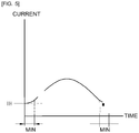
- FIGS. 4 and 5 are graphs showing an operating current of a TRIAC dimmer in a dimming period, according to an embodiment of the present invention.
- FIG. 4 is a graph showing the operating current of the TRIAC dimmer in the dimming period when the load 200 is not configured.
- a curved line indicates the operating current of the TRIAC dimmer, and a dashed line indicates a holding current of the TRIAC dimmer.
- the operating current of the TRIAC dimmer drops below the holding current of the TRIAC dimmer in the minimum dimming level (MIN) of the dimming period. Accordingly, the TRIAC dimmer turns off in these ranges as described above with reference to FIG. 1 .
- FIG. 5 is a graph showing the operating current of the TRIAC dimmer in the dimming period when the load 200 is provided.
- FIG. 5 shows that, when the load 200 is provided, the operating current of the TRIAC dimmer does not drop below the holding current of the TRIAC dimmer in the minimum dimming level (MIN) of the dimming period. Accordingly, the TRIAC dimmer may maintain the ON state even in these ranges.
- MIN minimum dimming level
- an operating current of a TRIAC dimmer may be prevented from dropping below a holding current in the minimum dimming level of the dimmer, and thus flickering of a light emitting diode (LED) may be prevented.
- LED light emitting diode
Landscapes
- Circuit Arrangement For Electric Light Sources In General (AREA)
Priority Applications (1)
| Application Number | Priority Date | Filing Date | Title |
|---|---|---|---|
| EP18172656.3A EP3399845A1 (de) | 2012-06-04 | 2013-06-03 | Led-beleuchtungsvorrichtung |
Applications Claiming Priority (2)
| Application Number | Priority Date | Filing Date | Title |
|---|---|---|---|
| KR1020120059977A KR101341976B1 (ko) | 2012-06-04 | 2012-06-04 | 엘이디 조명장치 |
| EP13800065.8A EP2858460B1 (de) | 2012-06-04 | 2013-06-03 | Led-beleuchtungsvorrichtung |
Related Parent Applications (1)
| Application Number | Title | Priority Date | Filing Date |
|---|---|---|---|
| EP13800065.8A Division EP2858460B1 (de) | 2012-06-04 | 2013-06-03 | Led-beleuchtungsvorrichtung |
Related Child Applications (1)
| Application Number | Title | Priority Date | Filing Date |
|---|---|---|---|
| EP18172656.3A Division EP3399845A1 (de) | 2012-06-04 | 2013-06-03 | Led-beleuchtungsvorrichtung |
Publications (1)
| Publication Number | Publication Date |
|---|---|
| EP3288346A1 true EP3288346A1 (de) | 2018-02-28 |
Family
ID=49712245
Family Applications (3)
| Application Number | Title | Priority Date | Filing Date |
|---|---|---|---|
| EP13800065.8A Not-in-force EP2858460B1 (de) | 2012-06-04 | 2013-06-03 | Led-beleuchtungsvorrichtung |
| EP17192653.8A Withdrawn EP3288346A1 (de) | 2012-06-04 | 2013-06-03 | Led-beleuchtungsvorrichtung |
| EP18172656.3A Withdrawn EP3399845A1 (de) | 2012-06-04 | 2013-06-03 | Led-beleuchtungsvorrichtung |
Family Applications Before (1)
| Application Number | Title | Priority Date | Filing Date |
|---|---|---|---|
| EP13800065.8A Not-in-force EP2858460B1 (de) | 2012-06-04 | 2013-06-03 | Led-beleuchtungsvorrichtung |
Family Applications After (1)
| Application Number | Title | Priority Date | Filing Date |
|---|---|---|---|
| EP18172656.3A Withdrawn EP3399845A1 (de) | 2012-06-04 | 2013-06-03 | Led-beleuchtungsvorrichtung |
Country Status (6)
| Country | Link |
|---|---|
| US (2) | US9408263B2 (de) |
| EP (3) | EP2858460B1 (de) |
| JP (1) | JP2015521362A (de) |
| KR (1) | KR101341976B1 (de) |
| CN (2) | CN106304486B (de) |
| WO (1) | WO2013183893A1 (de) |
Families Citing this family (4)
| Publication number | Priority date | Publication date | Assignee | Title |
|---|---|---|---|---|
| KR102246647B1 (ko) * | 2014-06-12 | 2021-04-30 | 서울반도체 주식회사 | 교류구동 발광소자의 조명장치 |
| TWI597930B (zh) * | 2015-02-06 | 2017-09-01 | Use to change the conduction angle as the control command of the control device | |
| US10178717B2 (en) | 2017-03-09 | 2019-01-08 | Dongming Li | Lamp-control circuit for lamp array emitting constant light output |
| RU183081U1 (ru) * | 2018-05-15 | 2018-09-10 | Владимир Филиппович Ермаков | Светодиодный выпрямительный мост Ермакова |
Citations (2)
| Publication number | Priority date | Publication date | Assignee | Title |
|---|---|---|---|---|
| KR20110019557A (ko) * | 2009-08-20 | 2011-02-28 | 성호전자(주) | 조광기와 결합되는 엘이디 조명용 에스엠피에스의 플리커 방지 회로 |
| KR101055865B1 (ko) | 2009-06-25 | 2011-08-09 | 박찬수 | 자기식 안정기를 이용한 조도제어 시스템 |
Family Cites Families (17)
| Publication number | Priority date | Publication date | Assignee | Title |
|---|---|---|---|---|
| US6452343B2 (en) * | 1999-11-17 | 2002-09-17 | Koninklijke Philips Electronics N.V. | Ballast circuit |
| JP4370794B2 (ja) * | 2003-03-26 | 2009-11-25 | パナソニック電工株式会社 | Led調光点灯装置及び照明器具 |
| GB0617393D0 (en) * | 2006-09-04 | 2006-10-11 | Lutron Electronics Co | Variable load circuits for use with lighting control devices |
| US8035318B2 (en) * | 2008-06-30 | 2011-10-11 | Neptun Light, Inc. | Apparatus and method enabling fully dimmable operation of a compact fluorescent lamp |
| JP5333768B2 (ja) | 2009-09-04 | 2013-11-06 | 東芝ライテック株式会社 | Led点灯装置および照明装置 |
| US8664881B2 (en) * | 2009-11-25 | 2014-03-04 | Lutron Electronics Co., Inc. | Two-wire dimmer switch for low-power loads |
| JP5214585B2 (ja) * | 2009-12-25 | 2013-06-19 | シャープ株式会社 | Led駆動回路、位相制御式調光器、led照明灯具、led照明機器、及びled照明システム |
| TW201141303A (en) * | 2010-05-07 | 2011-11-16 | Light Engine Ltd | Triac dimmable power supply unit for LED |
| WO2011148590A1 (ja) * | 2010-05-26 | 2011-12-01 | パナソニック株式会社 | Ledの点灯回路、ランプおよび照明装置 |
| JP5079855B2 (ja) * | 2010-08-24 | 2012-11-21 | シャープ株式会社 | Led駆動回路及びこれを用いたled照明灯具 |
| RU2589734C2 (ru) * | 2011-03-28 | 2016-07-10 | Конинклейке Филипс Н.В. | Устройство и способ возбуждения для возбуждения нагрузки, в частности, блока светодиодов |
| US8497637B2 (en) | 2011-04-13 | 2013-07-30 | Gang Gary Liu | Constant voltage dimmable LED driver |
| CN202135377U (zh) * | 2011-07-21 | 2012-02-01 | 北京源点新智科技有限公司 | Led可调光驱动电源控制电路及其控制模块 |
| US8624514B2 (en) * | 2012-01-13 | 2014-01-07 | Power Integrations, Inc. | Feed forward imbalance corrector circuit |
| US20140265898A1 (en) * | 2013-03-15 | 2014-09-18 | Power Integrations, Inc. | Lossless preload for led driver with extended dimming |
| JP6103478B2 (ja) * | 2013-03-22 | 2017-03-29 | 東芝ライテック株式会社 | 電源回路及び照明装置 |
| JP6482544B2 (ja) * | 2013-10-15 | 2019-03-13 | フィリップス ライティング ホールディング ビー ヴィ | 照明要素用の駆動ユニットとその動作方法 |
-
2012
- 2012-06-04 KR KR1020120059977A patent/KR101341976B1/ko active Active
-
2013
- 2013-06-03 JP JP2015514927A patent/JP2015521362A/ja active Pending
- 2013-06-03 EP EP13800065.8A patent/EP2858460B1/de not_active Not-in-force
- 2013-06-03 EP EP17192653.8A patent/EP3288346A1/de not_active Withdrawn
- 2013-06-03 EP EP18172656.3A patent/EP3399845A1/de not_active Withdrawn
- 2013-06-03 WO PCT/KR2013/004866 patent/WO2013183893A1/ko not_active Ceased
- 2013-06-03 CN CN201610710397.2A patent/CN106304486B/zh not_active Expired - Fee Related
- 2013-06-03 US US14/405,246 patent/US9408263B2/en active Active
- 2013-06-03 CN CN201380025925.5A patent/CN104303601B/zh not_active Expired - Fee Related
-
2016
- 2016-06-25 US US15/193,028 patent/US9713208B2/en active Active
Patent Citations (2)
| Publication number | Priority date | Publication date | Assignee | Title |
|---|---|---|---|---|
| KR101055865B1 (ko) | 2009-06-25 | 2011-08-09 | 박찬수 | 자기식 안정기를 이용한 조도제어 시스템 |
| KR20110019557A (ko) * | 2009-08-20 | 2011-02-28 | 성호전자(주) | 조광기와 결합되는 엘이디 조명용 에스엠피에스의 플리커 방지 회로 |
Also Published As
| Publication number | Publication date |
|---|---|
| US9713208B2 (en) | 2017-07-18 |
| KR20130136284A (ko) | 2013-12-12 |
| CN106304486B (zh) | 2019-01-15 |
| EP2858460B1 (de) | 2017-09-27 |
| JP2015521362A (ja) | 2015-07-27 |
| EP2858460A4 (de) | 2016-05-25 |
| US20150156837A1 (en) | 2015-06-04 |
| EP3399845A1 (de) | 2018-11-07 |
| KR101341976B1 (ko) | 2013-12-16 |
| WO2013183893A1 (ko) | 2013-12-12 |
| US20160309556A1 (en) | 2016-10-20 |
| CN104303601B (zh) | 2016-09-14 |
| CN104303601A (zh) | 2015-01-21 |
| CN106304486A (zh) | 2017-01-04 |
| EP2858460A1 (de) | 2015-04-08 |
| US9408263B2 (en) | 2016-08-02 |
Similar Documents
| Publication | Publication Date | Title |
|---|---|---|
| US9730289B1 (en) | Solid state light fixtures having ultra-low dimming capabilities and related driver circuits and methods | |
| US8680787B2 (en) | Load control device for a light-emitting diode light source | |
| TWI420960B (zh) | Led驅動電路、調光裝置、led照明器具、led照明裝置、及led照明系統 | |
| CN102378450B (zh) | Led驱动电路和使用led驱动电路的led照明装置 | |
| US9674918B2 (en) | Illumination system and luminaire | |
| CN103108441B (zh) | Led驱动电路及使用该led驱动电路的led照明灯具 | |
| EP2731405A1 (de) | Stromfreier Ablass | |
| CN105325061B (zh) | Led照明装置及其控制电路 | |
| CN105657932B (zh) | 光源驱动电路及亮度和色温控制器 | |
| CN105340367A (zh) | Led照明装置及其控制电路 | |
| US9713208B2 (en) | LED lighting device | |
| US20160021715A1 (en) | Light emitting device driver circuit and control circuit and control method thereof | |
| CN111972048B (zh) | 照明系统的电压互感器 | |
| KR101326988B1 (ko) | 블리드 회로, 이를 포함하는 조명 제어 회로, 조명 제어 방법 | |
| KR101349516B1 (ko) | Led 전원 장치. | |
| JP6827199B2 (ja) | 調光制御装置、照明器具、及び、制御方法 | |
| JP2014216320A (ja) | 光源を駆動する回路および方法 | |
| KR20140107837A (ko) | 발광 다이오드 조명 장치 및 그의 제어 회로 | |
| KR101597773B1 (ko) | Led 조명기구의 절전 장치 | |
| JP7463844B2 (ja) | 点灯装置および照明器具 | |
| KR102286777B1 (ko) | 발광 다이오드 조명 장치 | |
| JP6176568B2 (ja) | 点灯装置及び照明器具 | |
| TW201408129A (zh) | 發光二極體控制電路及其發光裝置 |
Legal Events
| Date | Code | Title | Description |
|---|---|---|---|
| PUAI | Public reference made under article 153(3) epc to a published international application that has entered the european phase |
Free format text: ORIGINAL CODE: 0009012 |
|
| STAA | Information on the status of an ep patent application or granted ep patent |
Free format text: STATUS: THE APPLICATION HAS BEEN PUBLISHED |
|
| AC | Divisional application: reference to earlier application |
Ref document number: 2858460 Country of ref document: EP Kind code of ref document: P |
|
| AK | Designated contracting states |
Kind code of ref document: A1 Designated state(s): AL AT BE BG CH CY CZ DE DK EE ES FI FR GB GR HR HU IE IS IT LI LT LU LV MC MK MT NL NO PL PT RO RS SE SI SK SM TR |
|
| STAA | Information on the status of an ep patent application or granted ep patent |
Free format text: STATUS: REQUEST FOR EXAMINATION WAS MADE |
|
| 17P | Request for examination filed |
Effective date: 20180720 |
|
| RBV | Designated contracting states (corrected) |
Designated state(s): AL AT BE BG CH CY CZ DE DK EE ES FI FR GB GR HR HU IE IS IT LI LT LU LV MC MK MT NL NO PL PT RO RS SE SI SK SM TR |
|
| STAA | Information on the status of an ep patent application or granted ep patent |
Free format text: STATUS: EXAMINATION IS IN PROGRESS |
|
| 17Q | First examination report despatched |
Effective date: 20190605 |
|
| STAA | Information on the status of an ep patent application or granted ep patent |
Free format text: STATUS: THE APPLICATION IS DEEMED TO BE WITHDRAWN |
|
| 18D | Application deemed to be withdrawn |
Effective date: 20210112 |