EP3287563B1 - Rope and manufacturing method therefor - Google Patents
Rope and manufacturing method therefor Download PDFInfo
- Publication number
- EP3287563B1 EP3287563B1 EP16798614.0A EP16798614A EP3287563B1 EP 3287563 B1 EP3287563 B1 EP 3287563B1 EP 16798614 A EP16798614 A EP 16798614A EP 3287563 B1 EP3287563 B1 EP 3287563B1
- Authority
- EP
- European Patent Office
- Prior art keywords
- rope
- yarn
- resin
- layer
- affinity
- Prior art date
- Legal status (The legal status is an assumption and is not a legal conclusion. Google has not performed a legal analysis and makes no representation as to the accuracy of the status listed.)
- Active
Links
- 238000004519 manufacturing process Methods 0.000 title claims description 39
- 229920005989 resin Polymers 0.000 claims description 194
- 239000011347 resin Substances 0.000 claims description 194
- 239000011248 coating agent Substances 0.000 claims description 76
- 238000000576 coating method Methods 0.000 claims description 76
- 239000010410 layer Substances 0.000 claims description 60
- 239000011247 coating layer Substances 0.000 claims description 56
- 230000002209 hydrophobic effect Effects 0.000 claims description 53
- 239000000835 fiber Substances 0.000 claims description 37
- 238000000034 method Methods 0.000 claims description 29
- -1 polyethylene Polymers 0.000 claims description 24
- 239000004698 Polyethylene Substances 0.000 claims description 21
- 229920000573 polyethylene Polymers 0.000 claims description 20
- 239000011230 binding agent Substances 0.000 claims description 11
- 230000002633 protecting effect Effects 0.000 claims description 9
- 230000002708 enhancing effect Effects 0.000 claims description 5
- 239000013535 sea water Substances 0.000 description 26
- 239000004576 sand Substances 0.000 description 21
- 238000012360 testing method Methods 0.000 description 17
- 239000012535 impurity Substances 0.000 description 14
- 239000000463 material Substances 0.000 description 13
- 230000002035 prolonged effect Effects 0.000 description 10
- XLYOFNOQVPJJNP-UHFFFAOYSA-N water Substances O XLYOFNOQVPJJNP-UHFFFAOYSA-N 0.000 description 9
- 238000005452 bending Methods 0.000 description 8
- 230000002093 peripheral effect Effects 0.000 description 8
- 230000000052 comparative effect Effects 0.000 description 7
- 229920000785 ultra high molecular weight polyethylene Polymers 0.000 description 7
- 239000004699 Ultra-high molecular weight polyethylene Substances 0.000 description 6
- 238000007598 dipping method Methods 0.000 description 6
- 239000000839 emulsion Substances 0.000 description 6
- 239000000203 mixture Substances 0.000 description 6
- 239000000945 filler Substances 0.000 description 5
- 230000005484 gravity Effects 0.000 description 5
- 125000000524 functional group Chemical group 0.000 description 4
- 239000002699 waste material Substances 0.000 description 4
- QVGXLLKOCUKJST-UHFFFAOYSA-N atomic oxygen Chemical compound [O] QVGXLLKOCUKJST-UHFFFAOYSA-N 0.000 description 3
- 230000000694 effects Effects 0.000 description 3
- 206010016256 fatigue Diseases 0.000 description 3
- 229910052760 oxygen Inorganic materials 0.000 description 3
- 239000001301 oxygen Substances 0.000 description 3
- 230000035939 shock Effects 0.000 description 3
- 239000000126 substance Substances 0.000 description 3
- 229920002994 synthetic fiber Polymers 0.000 description 3
- 239000012209 synthetic fiber Substances 0.000 description 3
- 229920005992 thermoplastic resin Polymers 0.000 description 3
- 239000004215 Carbon black (E152) Substances 0.000 description 2
- YCKRFDGAMUMZLT-UHFFFAOYSA-N Fluorine atom Chemical compound [F] YCKRFDGAMUMZLT-UHFFFAOYSA-N 0.000 description 2
- MHAJPDPJQMAIIY-UHFFFAOYSA-N Hydrogen peroxide Chemical compound OO MHAJPDPJQMAIIY-UHFFFAOYSA-N 0.000 description 2
- CBENFWSGALASAD-UHFFFAOYSA-N Ozone Chemical compound [O-][O+]=O CBENFWSGALASAD-UHFFFAOYSA-N 0.000 description 2
- NIXOWILDQLNWCW-UHFFFAOYSA-N acrylic acid group Chemical group C(C=C)(=O)O NIXOWILDQLNWCW-UHFFFAOYSA-N 0.000 description 2
- XECAHXYUAAWDEL-UHFFFAOYSA-N acrylonitrile butadiene styrene Chemical compound C=CC=C.C=CC#N.C=CC1=CC=CC=C1 XECAHXYUAAWDEL-UHFFFAOYSA-N 0.000 description 2
- 229920000122 acrylonitrile butadiene styrene Polymers 0.000 description 2
- 239000004676 acrylonitrile butadiene styrene Substances 0.000 description 2
- 125000000217 alkyl group Chemical group 0.000 description 2
- 239000002131 composite material Substances 0.000 description 2
- 238000011437 continuous method Methods 0.000 description 2
- 230000008878 coupling Effects 0.000 description 2
- 238000010168 coupling process Methods 0.000 description 2
- 238000005859 coupling reaction Methods 0.000 description 2
- 238000011156 evaluation Methods 0.000 description 2
- 230000001747 exhibiting effect Effects 0.000 description 2
- 229910052731 fluorine Inorganic materials 0.000 description 2
- 239000011737 fluorine Substances 0.000 description 2
- 238000005187 foaming Methods 0.000 description 2
- 229930195733 hydrocarbon Natural products 0.000 description 2
- 150000002430 hydrocarbons Chemical class 0.000 description 2
- 238000007254 oxidation reaction Methods 0.000 description 2
- 239000002245 particle Substances 0.000 description 2
- 229920000642 polymer Polymers 0.000 description 2
- 229920001343 polytetrafluoroethylene Polymers 0.000 description 2
- 239000004810 polytetrafluoroethylene Substances 0.000 description 2
- VGGSQFUCUMXWEO-UHFFFAOYSA-N Ethene Chemical compound C=C VGGSQFUCUMXWEO-UHFFFAOYSA-N 0.000 description 1
- JOYRKODLDBILNP-UHFFFAOYSA-N Ethyl urethane Chemical compound CCOC(N)=O JOYRKODLDBILNP-UHFFFAOYSA-N 0.000 description 1
- 239000005977 Ethylene Substances 0.000 description 1
- 101100136063 Mycobacterium tuberculosis (strain ATCC 25618 / H37Rv) PE11 gene Proteins 0.000 description 1
- 239000004743 Polypropylene Substances 0.000 description 1
- 229920002396 Polyurea Polymers 0.000 description 1
- 229910000831 Steel Inorganic materials 0.000 description 1
- 238000005299 abrasion Methods 0.000 description 1
- 238000007718 adhesive strength test Methods 0.000 description 1
- 150000001336 alkenes Chemical class 0.000 description 1
- 230000015572 biosynthetic process Effects 0.000 description 1
- 229920001400 block copolymer Polymers 0.000 description 1
- 239000006229 carbon black Substances 0.000 description 1
- 238000006243 chemical reaction Methods 0.000 description 1
- 239000011280 coal tar Substances 0.000 description 1
- 238000013329 compounding Methods 0.000 description 1
- 238000010276 construction Methods 0.000 description 1
- 229920001577 copolymer Polymers 0.000 description 1
- 239000011162 core material Substances 0.000 description 1
- 238000005260 corrosion Methods 0.000 description 1
- 230000007797 corrosion Effects 0.000 description 1
- 238000000354 decomposition reaction Methods 0.000 description 1
- 230000001419 dependent effect Effects 0.000 description 1
- 239000003814 drug Substances 0.000 description 1
- 229940079593 drug Drugs 0.000 description 1
- 239000004744 fabric Substances 0.000 description 1
- 239000002657 fibrous material Substances 0.000 description 1
- 238000007667 floating Methods 0.000 description 1
- 239000011521 glass Substances 0.000 description 1
- 238000000227 grinding Methods 0.000 description 1
- 238000007654 immersion Methods 0.000 description 1
- JEIPFZHSYJVQDO-UHFFFAOYSA-N iron(III) oxide Inorganic materials O=[Fe]O[Fe]=O JEIPFZHSYJVQDO-UHFFFAOYSA-N 0.000 description 1
- 238000009940 knitting Methods 0.000 description 1
- 239000004816 latex Substances 0.000 description 1
- 229920000126 latex Polymers 0.000 description 1
- 239000007788 liquid Substances 0.000 description 1
- JRZJOMJEPLMPRA-UHFFFAOYSA-N olefin Natural products CCCCCCCC=C JRZJOMJEPLMPRA-UHFFFAOYSA-N 0.000 description 1
- 230000003647 oxidation Effects 0.000 description 1
- 238000009832 plasma treatment Methods 0.000 description 1
- 229920001155 polypropylene Polymers 0.000 description 1
- 239000008262 pumice Substances 0.000 description 1
- 239000002994 raw material Substances 0.000 description 1
- 229920005573 silicon-containing polymer Polymers 0.000 description 1
- 238000005507 spraying Methods 0.000 description 1
- 239000010959 steel Substances 0.000 description 1
- 238000009864 tensile test Methods 0.000 description 1
- 235000013311 vegetables Nutrition 0.000 description 1
- 238000004804 winding Methods 0.000 description 1
Images


Classifications
-
- D—TEXTILES; PAPER
- D06—TREATMENT OF TEXTILES OR THE LIKE; LAUNDERING; FLEXIBLE MATERIALS NOT OTHERWISE PROVIDED FOR
- D06M—TREATMENT, NOT PROVIDED FOR ELSEWHERE IN CLASS D06, OF FIBRES, THREADS, YARNS, FABRICS, FEATHERS OR FIBROUS GOODS MADE FROM SUCH MATERIALS
- D06M10/00—Physical treatment of fibres, threads, yarns, fabrics, or fibrous goods made from such materials, e.g. ultrasonic, corona discharge, irradiation, electric currents, or magnetic fields; Physical treatment combined with treatment with chemical compounds or elements
- D06M10/02—Physical treatment of fibres, threads, yarns, fabrics, or fibrous goods made from such materials, e.g. ultrasonic, corona discharge, irradiation, electric currents, or magnetic fields; Physical treatment combined with treatment with chemical compounds or elements ultrasonic or sonic; Corona discharge
- D06M10/025—Corona discharge or low temperature plasma
-
- D—TEXTILES; PAPER
- D07—ROPES; CABLES OTHER THAN ELECTRIC
- D07B—ROPES OR CABLES IN GENERAL
- D07B1/00—Constructional features of ropes or cables
- D07B1/02—Ropes built-up from fibrous or filamentary material, e.g. of vegetable origin, of animal origin, regenerated cellulose, plastics
-
- D—TEXTILES; PAPER
- D06—TREATMENT OF TEXTILES OR THE LIKE; LAUNDERING; FLEXIBLE MATERIALS NOT OTHERWISE PROVIDED FOR
- D06M—TREATMENT, NOT PROVIDED FOR ELSEWHERE IN CLASS D06, OF FIBRES, THREADS, YARNS, FABRICS, FEATHERS OR FIBROUS GOODS MADE FROM SUCH MATERIALS
- D06M10/00—Physical treatment of fibres, threads, yarns, fabrics, or fibrous goods made from such materials, e.g. ultrasonic, corona discharge, irradiation, electric currents, or magnetic fields; Physical treatment combined with treatment with chemical compounds or elements
- D06M10/04—Physical treatment combined with treatment with chemical compounds or elements
- D06M10/06—Inorganic compounds or elements
-
- D—TEXTILES; PAPER
- D06—TREATMENT OF TEXTILES OR THE LIKE; LAUNDERING; FLEXIBLE MATERIALS NOT OTHERWISE PROVIDED FOR
- D06M—TREATMENT, NOT PROVIDED FOR ELSEWHERE IN CLASS D06, OF FIBRES, THREADS, YARNS, FABRICS, FEATHERS OR FIBROUS GOODS MADE FROM SUCH MATERIALS
- D06M15/00—Treating fibres, threads, yarns, fabrics, or fibrous goods made from such materials, with macromolecular compounds; Such treatment combined with mechanical treatment
- D06M15/19—Treating fibres, threads, yarns, fabrics, or fibrous goods made from such materials, with macromolecular compounds; Such treatment combined with mechanical treatment with synthetic macromolecular compounds
-
- D—TEXTILES; PAPER
- D07—ROPES; CABLES OTHER THAN ELECTRIC
- D07B—ROPES OR CABLES IN GENERAL
- D07B1/00—Constructional features of ropes or cables
- D07B1/16—Ropes or cables with an enveloping sheathing or inlays of rubber or plastics
-
- D—TEXTILES; PAPER
- D07—ROPES; CABLES OTHER THAN ELECTRIC
- D07B—ROPES OR CABLES IN GENERAL
- D07B5/00—Making ropes or cables from special materials or of particular form
- D07B5/005—Making ropes or cables from special materials or of particular form characterised by their outer shape or surface properties
- D07B5/006—Making ropes or cables from special materials or of particular form characterised by their outer shape or surface properties by the properties of an outer surface polymeric coating
-
- D—TEXTILES; PAPER
- D06—TREATMENT OF TEXTILES OR THE LIKE; LAUNDERING; FLEXIBLE MATERIALS NOT OTHERWISE PROVIDED FOR
- D06M—TREATMENT, NOT PROVIDED FOR ELSEWHERE IN CLASS D06, OF FIBRES, THREADS, YARNS, FABRICS, FEATHERS OR FIBROUS GOODS MADE FROM SUCH MATERIALS
- D06M2101/00—Chemical constitution of the fibres, threads, yarns, fabrics or fibrous goods made from such materials, to be treated
- D06M2101/16—Synthetic fibres, other than mineral fibres
- D06M2101/18—Synthetic fibres consisting of macromolecular compounds obtained by reactions only involving carbon-to-carbon unsaturated bonds
- D06M2101/20—Polyalkenes, polymers or copolymers of compounds with alkenyl groups bonded to aromatic groups
-
- D—TEXTILES; PAPER
- D06—TREATMENT OF TEXTILES OR THE LIKE; LAUNDERING; FLEXIBLE MATERIALS NOT OTHERWISE PROVIDED FOR
- D06M—TREATMENT, NOT PROVIDED FOR ELSEWHERE IN CLASS D06, OF FIBRES, THREADS, YARNS, FABRICS, FEATHERS OR FIBROUS GOODS MADE FROM SUCH MATERIALS
- D06M2200/00—Functionality of the treatment composition and/or properties imparted to the textile material
- D06M2200/10—Repellency against liquids
- D06M2200/12—Hydrophobic properties
-
- D—TEXTILES; PAPER
- D07—ROPES; CABLES OTHER THAN ELECTRIC
- D07B—ROPES OR CABLES IN GENERAL
- D07B2201/00—Ropes or cables
- D07B2201/20—Rope or cable components
- D07B2201/2015—Strands
- D07B2201/2041—Strands characterised by the materials used
-
- D—TEXTILES; PAPER
- D07—ROPES; CABLES OTHER THAN ELECTRIC
- D07B—ROPES OR CABLES IN GENERAL
- D07B2201/00—Ropes or cables
- D07B2201/20—Rope or cable components
- D07B2201/2015—Strands
- D07B2201/2042—Strands characterised by a coating
- D07B2201/2044—Strands characterised by a coating comprising polymers
-
- D—TEXTILES; PAPER
- D07—ROPES; CABLES OTHER THAN ELECTRIC
- D07B—ROPES OR CABLES IN GENERAL
- D07B2501/00—Application field
- D07B2501/20—Application field related to ropes or cables
- D07B2501/2061—Ship moorings
-
- D—TEXTILES; PAPER
- D10—INDEXING SCHEME ASSOCIATED WITH SUBLASSES OF SECTION D, RELATING TO TEXTILES
- D10B—INDEXING SCHEME ASSOCIATED WITH SUBLASSES OF SECTION D, RELATING TO TEXTILES
- D10B2321/00—Fibres made from polymers obtained by reactions only involving carbon-to-carbon unsaturated bonds
- D10B2321/02—Fibres made from polymers obtained by reactions only involving carbon-to-carbon unsaturated bonds polyolefins
- D10B2321/021—Fibres made from polymers obtained by reactions only involving carbon-to-carbon unsaturated bonds polyolefins polyethylene
- D10B2321/0211—Fibres made from polymers obtained by reactions only involving carbon-to-carbon unsaturated bonds polyolefins polyethylene high-strength or high-molecular-weight polyethylene, e.g. ultra-high molecular weight polyethylene [UHMWPE]
-
- D—TEXTILES; PAPER
- D10—INDEXING SCHEME ASSOCIATED WITH SUBLASSES OF SECTION D, RELATING TO TEXTILES
- D10B—INDEXING SCHEME ASSOCIATED WITH SUBLASSES OF SECTION D, RELATING TO TEXTILES
- D10B2401/00—Physical properties
- D10B2401/02—Moisture-responsive characteristics
- D10B2401/021—Moisture-responsive characteristics hydrophobic
Definitions
- the present invention relates to a rope and a method of manufacturing the same.
- the present invention relates to a rope which has a light weight and a high strength and is excellent in a wear resistance and a method of manufacturing the same.
- a field of use of the rope according to the present invention is not particularly restricted but can be utilized in all technical fields.
- a typical example of use can include a rope for a marine structure and a rope for mooring a ship.
- a mooring buoy can be illustrated as an example of use of a mooring rope.
- upper ends of chains 101 are coupled to a mooring buoy B and an anchor AC is coupled to lower ends.
- the anchor AC is provided on a sea bottom and the mooring buoy B floats on a sea surface.
- a length of the chain 101 has a margin. In some cases, therefore, the chain 101 comes in contact with sand on a sea bottom or the like.
- the chain 101 itself is formed of steel and has a high strength, it tends to be deteriorated by rust. If sand on a sea bottom intrudes into a portion between adjacent chains 101 so that it is often rubbed many times, wear of a corrosion layer proceeds quickly and is thus broken away. For this reason, the chain 101 is to be exchanged every two years or the like. Although an exchanging work is carried out in the water, the chain 101 has a great weight and a diver cannot perform the work and a working ship is required. As a result, a working cost is increased.
- the related art for preventing the friction of a rope or the like includes JP H09-209280 A , JP 2000-178888 A , and JP 2007-320559 A .
- JP H09-209280 A discloses a rope-shaped thing in which a fiber structure obtained by twisting an organic fiber is set to be a core material portion and a surface thereof is coated with a thermoplastic resin.
- thermoplasticity Although the thermoplastic resin is convenient for coating formation, it has an unknown resistance in use for a long time with immersion in the sea.
- JP 2000-178888 A features a strand having a three-layer structure.
- An inner layer is a yarn obtained by collecting raw threads
- an outer intermediate layer thereof is a layer coated with a thermoplastic resin and an external layer on an outside thereof is a yarn obtained by twisting raw threads.
- the strand has a layer structure including an inner layer yarn, an intermediate coating layer and an outer layer yarn. For this reason, the strand is thickened and a rope obtained by knitting the thickened strand must be thick.
- a cover is attached to an outer periphery of a rope, and the cover is configured from a rectangular cover body using a cloth-shaped member, a band-shaped non-slip mat, a flap and a surface fastener and is used with a proper part of the rope covered therewith.
- the cover is partially attached because the operability of the rope is damaged by attachment to a full length of the rope. For this reason, a wear resistance cannot be given to the full length of the rope.
- CN 103 835 171 A discloses a resin compounding method for high-modulus polyethylene or ultra-high-molecular-weight polyethylene twisting rope.
- CN 102 094 343 A discloses an ultrahigh molecular weight polyethylene abrasion and temperature resistant composite braided rope.
- CN 203 729 133 U discloses a polyurea filling fiber rope.
- CN 201 605 478 U discloses an ultra high molecular weight polyethylene high temperature resistant six-strand rope, using ultra-high molecular weight polyethylene six-strand rope, which is defined by coating a layer of polytetrafluoroethylene on an outer layer of ultra-high molecular weight polyethylene six-strand rope.
- CN 104 514 150 A discloses a formula of ultrahigh molecular weight polyethylene coating liquid for coating ropes.
- JP 2009/001943 A discloses a rope which includes a plurality of strands formed by twisting a plurality of yarns composed of a synthetic fiber.
- the yarn constituting the outermost layer of the strand of the rope is a resin-treated yarn obtained by dispersing a resin on the surface of the synthetic fiber and between the synthetic fibers before forming the strand, and the multiple resin-treated yarns are twisted in a state arranged adjacent to each other along the circumferential direction of the strand to form a smooth outer circumference of the strand.
- WO 2011/015485 A discloses a high strength fibers including a coating of cross-linked silicone polymer, and ropes made thereof.
- WO 2013/036522 A discloses a surface treated yarn and fabric with enhanced physical and adhesion properties.
- the resin coating layer for protecting the rope is formed. Therefore, waste, sand or the like in the sea is prevented from intruding into the inner part of the rope. For this reason, wear is not caused by rubbing of the yarns or strands against each other. Even if the rope comes in contact with a fixed thing in the sea or on the sea, moreover, the direct contact of a rope body is avoided by the resin coating layer. For these reasons, a life of the robe can be enhanced.
- a protecting effect with the same performance can be obtained through a processing man-hour which is one-xth (x is three to five) as compared with the case in which the first yarn is coated with a resin.
- the resin of the inner coating layer causes the hydrophobic resin of the outer layer to strongly adhere to the yarn, the strand or the rope body. Therefore, a resin coating resistance can be increased.
- the hydrophobic resin layer prevents intrusion of sea water into the rope. Therefore, intrusion of sand in the sea water or the like is prevented. From this viewpoint, similarly, the life of the rope can be enhanced.
- the intrusion of the sea water into the rope is prevented so long as the hydrophobic resin layer is coated. Therefore, the sand in in the sea water or the like is prevented. From this viewpoint, similarly, the life of the rope can be enhanced.
- the affinity resin contained in the affinity and hydrophobic resin layer causes the hydrophobic resin of the outer layer to adhere to the yarn, the strand or the rope body. Therefore, a period for exhibiting the life of the rope can be prolonged.
- the hydrophobic resin prevents the sea water from intruding into the rope. Therefore, the intrusion of the sand in the sea water or the like can be prevented. From this viewpoint, similarly, the life of the rope can be enhanced.
- the oil content is removed through the pretreating step. Consequently, conditions for enabling resin coating are met. Subsequently, the external surface of the yarn or the strand is caused to have affinity to the resin. Therefore, the resin of the resin coating layer strongly adheres. Therefore, it is possible to obtain a rope protected firmly by the resin coating layer.
- a seventh aspect of the present disclosure when the second yarn is coated with a resin, it is possible to obtain a rope with the same performance through a processing man-hour (which is one-xth (x is three to five)) as compared with the case in which the first yarn is coated with a resin.
- the resin which has just been coated intrudes into the inner part of the yarn. Therefore, the resin serves as a binder for bundling taw threads constituting the yarn and reduces wear caused by rubbing if any. Even if the resin serves as the binder for bundling the raw threads constituting the yarn and the rubbing is caused, moreover, it reduces the wear caused thereby.
- the resin which has just been coated further intrudes into the inner part of the yarn. Therefore, the resin serves as a guard for preventing intrusion of a wearing material such as sea water, sand mixed therein or the like into the inner part of the rope. For this reason, a life for a long period can be held also in use in the sea.
- the resin which has just been coated when the drawing step is performed after the coating step, the resin which has just been coated also intrudes into the inner part of the yarn. Therefore, the resin serves as a binder for bundling raw threads constituting the yarn and reduces wear caused by rubbing if any. Moreover, the resin serves as a guard for preventing the intrusion of a wearing material such as sea water, sand mixed therein or the like into the inner part of the rope. Therefore, the life for a long period can be held also in use in the sea.
- a wearing material such as sea water, sand mixed therein or the like
- the resin which has just been coated intrudes into the inner part of the yarn. Therefore, the resin serves as a binder for bundling raw threads constituting the yarn and reduces wear caused by rubbing if any. Moreover, the resin serves as a guard for preventing the intrusion of a wearing material such as sea water, sand mixed therein or the like into the inner part of the rope. Therefore, the life for a long period can be held also in use in the sea.
- a wearing material such as sea water, sand mixed therein or the like
- Embodiments according to the present invention will be described in division into “a rope” and “a manufacturing method”.
- a yarn is obtained by twisting raw threads
- a strand is obtained by twisting a plurality of yarns
- a rope is obtained by rope-making through a plurality of strands.
- the numbers of the raw threads, yarns and strands are optional.
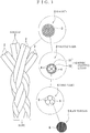
- FIG. 1 shows a typical example of the rope to which the present invention is applied, and the rope is configured as follows.
- a raw thread 5 is obtained by arranging 1580 fibers 6 in a diameter of 12 ⁇ m. When three raw threads 5 are used and twisted, a first yarn 4 is obtained. When four first yarns 4 are used and twisted, a second yarn 3 is obtained. When 24 second yarns 3 are used and twisted, a strand 2 is obtained. A rope 1 is obtained by using eight strands 2 to perform rope-making.
- a polyethylene fiber having an ultra high molecular weight is used for the raw thread 5.
- the polyethylene fiber having the ultra high molecular weight is polyethylene in which an ordinary molecular weight of 2 to 300000 is increased up to 100 to 7000000 and has the following features.
- the polyethylene fiber is :
- the rope according to the present invention has the basic structure described above, and furthermore, has a resin coating layer 10 formed therein.
- the resin coating layer 10 serves to protect the rope.
- the resin coating layer 10 is formed to prevent intrusion of impurities such as sand into the inner part of the rope even if the rope is used in the sea, and to cause the rope to be worn with difficulty even if it comes in strong contact with a fixed thing in the sea and on the sea, thereby protecting the rope 1 to prolong a life.
- the resin coating layer 10 is typically formed on an external surface of a yarn, particularly, an external surface of the second yarn 3.
- the resin coating layers 10 formed on an external surface of a strand and an external surface of a rope are included in the present invention. The reason is that the resin coating layer 10 can prevent intrusion of sand in the sea or the like and can also improve a wear resistance to external contact even if it is formed in any place of the external surface.
- the resin coating layer 10 is not formed on the external surface of the first yarn 4 but that of the second yarn 3, it is possible to produce a protecting effect with the same performance in a man hour which is one-xths (x is three to five) if the second yarn 3 is coated with a resin as compared with the case in which the first yarn 4 is coated with a resin.
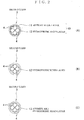
- a rope according to each of first to third embodiments applying three types of patterns in the resin coating layer 10 will be described with reference to FIG. 2 .
- the resin coating layer 10 provided on an outer periphery of the second yarn 3 is constituted by a resin layer 11 having affinity which is an inner coating layer and a hydrophobic resin layer 12 which is an outer coating layer formed on an external surface of the inner coating layer.
- the resin having affinity is a water dispersible composition having oxygen-containing functional groups and can include hydrocarbon oligomer, ethylene-based copolymer, olefin-based block copolymer, polypropylene-based emulsion, urethane-based emulsion, acrylic emulsion, acrylonitrile-butadiene-styrene emulsion, modified latex emulsion, modified acrylic emulsion and the like, for example.
- the resin may be a mixture constituted by at least two resins selected from them.
- the inner coating layer is formed by using a resin having affinity to the yarn which is surface-modified to be hydrophilic, an excellent adhesion to the second yarn 3 is exhibited. Consequently, the protecting performance of the coating resin layer 10 for the rope 1 can be enhanced.
- the outer coating layer is formed by a resin which is affinity and hydrophobic with respect to the affinity resin layer 11 of the inner coating layer.
- the hydrophobic resin can include fluorinated alkyl oligomer, organosilicon based polymer, coal tar, asphaltene and their mixtures and the like, for example, and is not restricted thereto.
- the hydrophobic resin layer 12 formed as described above repels sea water and prevents intrusion of impurities such as fine sand together with the sea water into the inner part of the rope 1
- the second yarn 3 having the resin coating layer 10 formed therein is braided as the strand 2 in accordance with a usual method as shown in FIG. 1 , and furthermore, is subjected to rope-making as the rope 1.
- the rope according to the first embodiment is thus obtained.
- the affinity resin layer 11 of the inner coating layer causes the hydrophobic resin layer 12 of the outer coating layer to strongly adhere to the external surface of the second yarn 3. Therefore, breakage of a rope structure can be prevented from being caused by wear so that a life of the rope can be prolonged.
- the hydrophobic resin layer 12 prevents the intrusion of sea water into the inner part of the rope 1. Consequently, the intrusion of impurities such as sand in the sea water can be prevented. Also in this respect, a wear resistance can be enhanced. Thus, the life of the rope can be prolonged.
- the affinity resin which has just been coated intrudes into an inner part of the second yarn 3.
- the resin intruding into the inner part serves as a binder for bundling raw threads constituted by a polyethylene fiber having an ultrahigh molecular weight forming the second yarn 3 to enhance the binding force of fibers. Even if the external coating layer breaks, moreover, the impurities such as fine stones are prevented from intruding into the inner part of the rope. Even if the fibers or yarns are rubbed against each other, furthermore, they act as friction reducing materials for reducing wear caused by the rubbing. From this viewpoint, furthermore, durability can be enhanced so that a life is prolonged.
- a resin coating layer 10 provided on an outer peripheral surface of a second yarn 3 includes only a hydrophobic resin layer 12 constituted by a hydrophobic resin as shown in FIG. 2(B) .
- the hydrophobic resin according to the first embodiment is particularly used without limit.
- the second yarn 3 having the hydrophobic resin layer 12 formed thereon is braided as a strand 2 and is further subjected to rope-making as a rope 1 as shown in FIG. 1 in accordance with a usual method.
- This is a rope according to the second embodiment.
- the rope 1 is coated with the hydrophobic resin layer 12 formed on the outer peripheral surface of the second yarn 3. Therefore, intrusion of the sea water into the rope is prevented. Consequently, intrusion of impurities such as sand in the sea water can be prevented. From this viewpoint, a wear resistance can be enhanced so that a life of the rope is also prolonged.
- the resin intruding into the inner part serves as a binder for bundling raw threads constituted by a polyethylene fiber having an ultrahigh molecular weight constituting the second yarn 3 to enhance the binding force of the fibers. Even if breakage or the like occurs in the outer coating layer, moreover, impurities such as small stones can be prevented from intruding into the inner part of the rope. Even if the fibers or yarns are rubbed against each other, furthermore, the resin serves as a friction reducing material for reducing wear caused by the rubbing. Also in this respect, therefore, durability can be enhanced and a life can be prolonged.
- a resin coating layer provided on an outer peripheral surface of a second yarn 3 is constituted by an affinity and hydrophobic resin layer 13.
- the affinity and hydrophobic resin layer 13 is constituted by a resin having both properties of adhesion to a surface-modified raw thread and hydrophobicity.
- the affinity and hydrophobic resin layer 13 may be a kind of resin or a mixture of at least two types of resins.
- the resin layer illustrated in the first embodiment or a mixture of at least two resins selected from the inner layer resins and the outer layer resins illustrated in the first embodiment is particularly used without limit.
- a filler into these resins in order to enhance a wear resistance of the resin itself.
- a filler it is desirable to use a fibrous material or a polymer bulk body in consideration of a bending resistance. Examples include a recycled fiber, a vegetable fiber, carbon black, an SBS filler, an ABS filler, a PTFE filler and the like.
- a second yarn 3 having the affinity and hydrophobic resin layer 13 formed thereon is braided as a strand 2 and is further subjected to rope-making as a rope 1 in accordance with a usual method as shown in FIG. 1 .
- the rope according to the third embodiment is thus obtained.
- an affinity resin contained in the affinity and hydrophobic resin layer 13 causes a hydrophobic resin of an outer layer to strongly adhere to the yarn 3. Therefore, a period for exhibiting a wear resistance can be prolonged.
- the hydrophobic resin prevents intrusion of sea water into the rope. Consequently, intrusion of impurities such as sand in the sea water can be prevented. From this viewpoint, similarly, the life of the rope can be enhanced.
- the affinity resin which has just performed coating intrudes into an inner part of the second yarn 3.
- the resin intruding into the inner part serves as a binder for bundling raw threads constituted by a polyethylene fiber having an ultrahigh molecular weight constituting the second yarn 3 to enhance the binding force of the fibers. Even if breakage or the like occurs in the outer coating layer, moreover, impurities such as small tones can be prevented from intruding into the inner part of the rope. Even if the fibers or yarns are rubbed against each other, furthermore, the resin serves as a friction reducing material for reducing wear caused by the rubbing. Also in this respect, therefore, durability can be enhanced and a life can be prolonged.
- the manufacturing method according to the present invention indicates a method of manufacturing a rope 1 which includes yarns 3 and 4 twisted by using a raw thread 5 of a polyethylene fiber having an ultrahigh molecular weight, and a strand 2 obtained by twisting he yarns 3 and 4, and is subjected to rope-making by the strand 2.
- the manufacturing method features to perform a pretreating step I of removing an oil content contained in the rope 1 to cause a surface to have affinity to a resin to be coated, and subsequently, a resin coating step II of forming, on outer surfaces of the yarns 3 and 4, an outer surface of the strand 2 or an outer surface of the rope 1, a resin coating layer 10 for protecting the rope.
- a pretreating step I of removing an oil content contained in the rope 1 to cause a surface to have affinity to a resin to be coated
- a resin coating step II of forming, on outer surfaces of the yarns 3 and 4, an outer surface of the strand 2 or an outer surface of the rope 1, a resin coating layer 10 for protecting the rope.
- FIG. 3 shows a method of manufacturing the rope ( Fig. 2(A) ) according to the first embodiment.
- the first yarn 4 constituted by the raw thread 5 of a polyethylene fiber having an ultrahigh molecular weight is twisted to make the second yarn 3 by a usual method.
- a pretreating step I and a resin coating step II which will be described below in detail are executed.
- Two methods including a) a UV treatment method and b) an atmospheric plasma method can be applied to the pretreating step I.
- UV treatment method hydrogen peroxide is exposed to ultraviolet rays to generate an active radical.
- a high voltage of approximately 10000 Volts is applied by using a high frequency power supply in the air to generate ozone or the like.
- the pretreating step can be performed.
- the oil content of the second yarn 3 is subjected to oxidation and decomposition. Consequently, the oil contents contained in the yarns 3 and 4 can be removed.
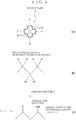
- an exposed surface f represents an outward surface of the first yarn 4 configuring a surface of the second yarn 3 shown in FIG. 4 and indicates a portion exposed to a pretreatment atmosphere.
- a portion shown in a thick line corresponds thereto.
- the first yarn 4 is constituted by the polyethylene fiber having an ultrahigh molecular weight. Therefore, a chemical formula thereof has a structure in which H is bonded to C.
- oxidation reaction occurs over the exposed surface of the polyethylene fiber having an ultrahigh molecular weight so that O and OH are introduced.
- O and OH are oxygen-containing functional groups.
- a hydrophilic resin easily adheres chemically. This treatment is referred to as a surface affinity enhancing treatment.
- a contact angle in the second yarn 3 before the execution of the pretreatment is approximately 90° and affinity enhancement is performed in such a manner that the contact angle after the pretreatment is equal to or smaller than 40°.
- the resin coating step II includes a first coating step II1 of forming an affinity resin layer on the exposed surface of the second yarn 3 subjected to the pretreating step I, a first drawing step 112 of pressurizing and drawing the second yarn 3 subjected to the first coating step from an outer periphery, a second coating step 113 of forming a hydrophobic resin layer on an outer surface of the affinity resin layer of the second yarn 3 subjected to the first drawing step 112, and a second drawing step 114 of pressurizing and drawing the second yarn 3 subjected to the second coating step 113 from an outer periphery.
- the first coating step II1 is executed by an optional method such as a method of spraying or dropping and applying an affinity resin in addition to a method of performing dipping the affinity resin into a water-dispersed tank.
- a dipping method may take a continuous construction method of bringing the second yarn 3 out while sequentially putting it into the tank or a batch mode for dipping the second yarn 3 in a certain amount into the tank and then bringing it up therefrom. Consequently, the affinity resin layer 11 is formed as an inner coating layer on the outer periphery of the second yarn 3.
- the continuous method is more suitable for long rope processing and a productivity can also be enhanced more greatly.
- the first drawing step 112 is executed after the first coating II1.
- the drawing process to be performed indicates pressurization from an outside of the second yarn 3 toward a center by a method of inserting the second yarn 3 through a dice or the like. By the pressurization, an affinity resin in a sufficient amount is infiltrated into the second yarn 3 while the excessive resin is scraped off.
- the affinity resin which has just performed coating intrudes into an inner part of the second yarn 3. Therefore, the resin intruding into the inner part serves as a binder for bundling raw threads constituted by a polyethylene fiber having an ultrahigh molecular weight constituting the second yarn 3 to increase the binding force of the fibers. Even if breakage or the like occurs over an outer coating layer, impurities such as small stones can be prevented from intruding into the inner part of the rope. Even if the fibers or yarns are rubbed against each other, furthermore, they serve as friction reducing materials for reducing wear caused by the rubbing. Also in this respect, durability is enhanced so that a life of the rope can be prolonged.
- the second coating step 113 is executed.
- the second coating step 113 may be executed by a method of performing dipping the hydrophobic resin into a water-dispersed tank or the like.
- the dipping method may take a continuous method of sequentially bringing the second yarn 3 out while putting it into the tank or a batch mode for dipping the second yarn 3 in a certain amount into the tank and then bringing it up. Consequently, the hydrophobic resin layer 12 is formed as an outer coating layer on the external surface of the inner coating layer (the affinity resin layer 11).
- the second drawing step 114 is executed after the second coating 113.
- the drawing treatment to be performed indicates pressurization from the outside of the second yarn 3 toward the center by the method of inserting the second yarn 3 through a dice or the like. By the pressurization, the hydrophobic resin is further infiltrated into the second yarn 3 while the excessive resin is scraped off.
- the hydrophobic resin which has just performed coating intrudes into an inner part of the yarn in addition to the affinity resin which has already intruded into the inner part earlier. Therefore, a repellency of the surfaces of the yarns 3 and 4 can be enhanced. For example, a contact angle reaches 110° or more. For this reason, the hydrophobic resin layer 12 serves as a guard for preventing intrusion of sea water or impurities such as sand mixed therein into the inner part of the rope. Also in use in the sea, a life for a long period can be held.
- the second yarn 3 subjected to the coating as described above is braided into the strand 2 in accordance with a usual method, and furthermore, is subjected to rope-making into the rope 1. Consequently, there is obtained the rope 1 (see FIG. 1 ) in which pattern coating shown in FIG. 2(A) is formed.
- FIG. 5 shows a method of manufacturing the rope ( Fig. 2(B) ) according to the second embodiment.
- the pretreating step I according to the present embodiment includes removal of an oil content and a treatment for giving affinity to a hydrophobic resin which is to be performed next.
- a treatment for giving affinity to a hydrophobic resin which is to be performed next.
- the affinity enhancing treatment it is possible to apply a UV treating method or an atmospheric plasma method which is employed in the first embodiment.
- the pretreating step I for giving affinity to a hydrophobic resin is almost the same as that described in the first manufacturing method and a treatment using only a different drug is suitable.
- C on the surface of the polyethylene fiber having an ultrahigh molecular weight causes a reaction so that H is substituted for fluorine-containing functional groups.
- the resin coating step II includes a coating step 113 of forming the hydrophobic resin layer 12 on the surface of the second yarn 3 subjected to the pretreating step I and a drawing step 114 of performing pressurization and drawing over a yarn subjected to the coating step 113 from an outer periphery.
- the first coating step II1 and the first drawing step 112 shown in FIG. 3 are omitted, and the second coating step 113 and the second drawing step 114 are used.
- the residual steps are the same as those in the first embodiment.
- hydrophobic resin forming the hydrophobic resin layer 12 which has been described above.
- the hydrophobic resin which has just been subjected to the coating also intrudes into an inner part of a yarn. Therefore, the repellency on the surfaces of the yarns 3 and 4 can be enhanced. For example, a contact angle reaches 110° or more.
- the hydrophobic resin layer 12 serves as a guard for preventing intrusion of impurities such as sea water or sand mixed therein into an inner part of a rope. Consequently, a life for a long period can be held also for use in the sea.
- the second yarn 3 subjected to the coating as described above is braided into a strand 2, and furthermore, is subjected to rope-making into the rope 1 in accordance with a usual method. Consequently, there is obtained the rope 1 (see FIG. 1 ) on which the pattern coating shown in FIG. 2(B) is formed.
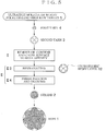
- FIG. 6 shows a method of manufacturing a rope ( FIG. 2(C) ) according to the third embodiment.
- the pretreating step I according to the present embodiment includes the same oil content removal as that in the first embodiment and a surface affinity enhancing treatment to be performed subsequently.
- the pretreating step I for giving affinity to a hydrophobic resin is almost the same as that described in the first manufacturing method.
- the resin coating step II includes a coating step 115 of forming an affinity and hydrophobic resin layer 13 on a surface of the second yarn 3 subjected to the pretreating step I, and a drawing step 116 of pressurizing and drawing the yarn subjected to the coating step 115 from an outer periphery.
- This manufacturing method uses a resin having both properties of an affinity resin and a hydrophobic resin in place of use of the hydrophobic resin in the manufacturing method shown in FIG. 5 .
- the affinity resin and the hydrophobic resin which have just performed the coating intrude into the inner part of the yarn. Therefore, these resins serve as binders for bundling raw threads formed by a polyethylene fiber having an ultrahigh molecular weight constituting a yarn so that the binding force of the fibers can be enhanced. Consequently, a bending resistance can be enhanced. Even if the fibers or yarns are rubbed against each other, moreover, they serve as friction reducing materials for reducing a wear caused thereby. From this viewpoint, similarly, the bending resistance can be enhanced. Furthermore, the repellencies of the surfaces of the yarns 3 and 4 can be enhanced.
- a contact angle reaches 110° or more.
- the hydrophobic resin layer 12 serves as a guard for preventing intrusion of a wearing material such as sea water or sand mixed therein into the inner part of the rope.
- a life for a long period can be held also for use in the sea.
- the second yarn 3 subjected to the coating as described above is braided into the strand 2, and furthermore, is subjected to rope-making into the rope 1 in accordance with a usual method. Consequently, there is obtained the rope 1 (see FIG. 1 ) having pattern coating formed thereon as shown in FIG. 2(C) .
- the first yarn 4 may be instead coated, and furthermore, the resin coating may be performed in the state of the strand 2 and the resin coating may be performed in the state of the rope 1.
- the rope 1 obtained by the manufacturing method has the following effects because it inherits properties of the polyethylene having an ultrahigh molecular weight, that is, 1) a high shock resistance, 2) an excellent wear resistance, 3) a smaller specific gravity than that of water and 4) no water absorbing property and an excellent dimensional stability.
- the resin coating layer 10 is provided. Therefore, the rope can be protected. Specifically, waste, sand or the like in the sear does not intrude into the inner part of the rope. For this reason, a wear is not caused by rubbing of the yarns or strands, and furthermore, direct contact of the robe body is avoided by the resin coating layer even if the rope comes in contact with a fixed thing in the sea or on the sea. Consequently, it is possible to produce an advantage of an enhancement in the wear resistance of the rope.
- a resin introducing into the inner part of the yarn serves as a binder or a friction reducing material. Therefore, a bending resistance can also be enhanced.
- the rope 1 in FIGS. 1 and 2(A) was prepared.
- 1580 polyethylene fibers 6 having ultrahigh molecular weights with a diameter of 12 ⁇ m were arranged to make the raw thread 5, three raw threads 5 were used and twisted to make the first yarn 4, four first yarns 4 were used and twisted to make the second yarn 3, four second yarns 3 were used and twisted to make the strand 2 and rope-making is performed by using eight strands 2.
- the rope 1 was manufactured by a first manufacturing method shown in FIG. 3 .
- a pretreating step I an atmospheric plasma method was used. Hydrocarbon oligomer was used for an affinity resin and fluorinated alkyl oligomer was used for a hydrophobic resin. Even if a UV treating method was used as the pretreating step I, it is possible to obtain the same result by the following tests.
- an S shape bend testing machine capable of winding a rope to be a testing material around three rollers (a diameter of 75 mm) so as to take an S shape, coupling a weight (100 kg) to one of rope ends and coupling the other rope end to a motor-operated disk.
- D represents an inner diameter of a sheave of 70 mm and d represents an outer shape of a second yarn of 2 mm.
- the PE11 container supplied by Sanplatec Corporation was used for a container.
- 300 cc of Sea water supplied by Gex Corporation was used for the artificial sea water.
- 40 g of SuperSol which is a porous and light foaming material (an artificial pumice obtained by grinding, burning and foaming a waste glass) supplied by Kokko Co., Ltd. was used for the abrasive.
- a close dimension to a particle size having a length of 20 mm, a width of 15 mm and a height of 10 mm was selected for a particle size of the abrasive.
- a second yarn was put in a PE container having artificial sea water and an abrasive therein, which was put in a rotary raw material agitating machine to continuously perform the wear test for five hours, thereby obtaining a breaking strength through an Amsler's tensile testing machine to calculate a residual strength ratio. Results are as follows.
- a residual strength ratio of 28.5% was obtained in the Comparative Example 1, while a residual strength ratio of 73.1 % was obtained in the Example 1.
- a residual strength ratio ranges from approximately 55% to 73 % and a double to threefold performance is obtained as compared with the Comparative Examples. Consequently, it is apparent that the rope according to the Example 1 has a very excellent wear resistance.
- a rope for mooring an offshore structure or a ship As a typical example of use, it is possible to illustrate a rope for mooring an offshore structure or a ship.
- a ship mooring buoy B floating on a sea surface and an anchor AC provided on a sea bottom are coupled to each other through the rope 1 according to the present invention.
- the rope 1 Since the rope 1 has a specific gravity of one or less, it is curved to float without hanging.
- the specific gravity of the rope for mooring is smaller than that of the sea water. Therefore, the rope does not come in contact with the sea bottom, and furthermore, a resin coating layer for protecting the rope is formed. Thus, waste, sand or the like in the sea can be prevented from intruding into the inner part of the rope.
- the rope according to the present invention can be utilized in all technical fields in addition to mooring in the sea or on the sea described above.
Description
- The present invention relates to a rope and a method of manufacturing the same. In more detail, the present invention relates to a rope which has a light weight and a high strength and is excellent in a wear resistance and a method of manufacturing the same.
- A field of use of the rope according to the present invention is not particularly restricted but can be utilized in all technical fields. A typical example of use can include a rope for a marine structure and a rope for mooring a ship.
- A mooring buoy can be illustrated as an example of use of a mooring rope. As shown in
FIG. 8 , upper ends ofchains 101 are coupled to a mooring buoy B and an anchor AC is coupled to lower ends. The anchor AC is provided on a sea bottom and the mooring buoy B floats on a sea surface. In consideration of the rise and fall of a tide, a length of thechain 101 has a margin. In some cases, therefore, thechain 101 comes in contact with sand on a sea bottom or the like. - Although the
chain 101 itself is formed of steel and has a high strength, it tends to be deteriorated by rust. If sand on a sea bottom intrudes into a portion betweenadjacent chains 101 so that it is often rubbed many times, wear of a corrosion layer proceeds quickly and is thus broken away. For this reason, thechain 101 is to be exchanged every two years or the like. Although an exchanging work is carried out in the water, thechain 101 has a great weight and a diver cannot perform the work and a working ship is required. As a result, a working cost is increased. - It is possible to solve the problem by using a rope in place of the
chain 101. For example, the exchanging work in the water can be performed with a small load. When the rope is used in the sea, however, there is a problem in that sand and other fine impurities in the sea intrude into an inner part from the mesh of the rope and the rope is thus broken away in the early stage due to a friction between the impurities and a rope fiber. - The related art for preventing the friction of a rope or the like includes
JP H09-209280 A JP 2000-178888 A JP 2007-320559 A -
JP H09-209280 A - Referring to
JP H09-209280 A -
JP 2000-178888 A - Moreover, the outer layer yarn exposed to an external surface of the strand is not protected by resin coating. In use in the sea, therefore, there is still a problem in that it is impossible to prevent wear from being caused by mixture of impurities in the sea, resulting in breakaway in the early stage.
- Referring to the related art disclosed in
JP 2007-320559 A - However, the cover cannot prevent the intrusion of gravel on a sea bottom from intruding into an inner part of the rope. Thus, there is a great restriction to use in the sea.
- Moreover, the cover is partially attached because the operability of the rope is damaged by attachment to a full length of the rope. For this reason, a wear resistance cannot be given to the full length of the rope.
-
CN 103 835 171 A discloses a resin compounding method for high-modulus polyethylene or ultra-high-molecular-weight polyethylene twisting rope. -
CN 102 094 343 A discloses an ultrahigh molecular weight polyethylene abrasion and temperature resistant composite braided rope. -
CN 203 729 133 U discloses a polyurea filling fiber rope. -
CN 201 605 478 U discloses an ultra high molecular weight polyethylene high temperature resistant six-strand rope, using ultra-high molecular weight polyethylene six-strand rope, which is defined by coating a layer of polytetrafluoroethylene on an outer layer of ultra-high molecular weight polyethylene six-strand rope. -
CN 104 514 150 A discloses a formula of ultrahigh molecular weight polyethylene coating liquid for coating ropes. -
JP 2009/001943 A -
WO 2011/015485 A discloses a high strength fibers including a coating of cross-linked silicone polymer, and ropes made thereof. -
WO 2013/036522 A discloses a surface treated yarn and fabric with enhanced physical and adhesion properties. - In consideration of the circumstances, it is an object of the present invention to provide a rope which is hard to wear regardless of use in the sea and can maintain a long life. Moreover, it is an object of the present invention to provide a manufacturing method which implements the rope.
- In accordance with the present invention, a rope and a method of manufacturing a rope, is provided as defined in the appended claims. Preferred embodiments of the present invention may be gathered from the dependent claims.
- According to a first aspect of the present disclosure, the resin coating layer for protecting the rope is formed. Therefore, waste, sand or the like in the sea is prevented from intruding into the inner part of the rope. For this reason, wear is not caused by rubbing of the yarns or strands against each other. Even if the rope comes in contact with a fixed thing in the sea or on the sea, moreover, the direct contact of a rope body is avoided by the resin coating layer. For these reasons, a life of the robe can be enhanced.
- According to a second aspect of the present disclosure, when the second yarn is coated with a resin, a protecting effect with the same performance can be obtained through a processing man-hour which is one-xth (x is three to five) as compared with the case in which the first yarn is coated with a resin.
- According to a third aspect of the present disclosure, the resin of the inner coating layer causes the hydrophobic resin of the outer layer to strongly adhere to the yarn, the strand or the rope body. Therefore, a resin coating resistance can be increased. In addition, the hydrophobic resin layer prevents intrusion of sea water into the rope. Therefore, intrusion of sand in the sea water or the like is prevented. From this viewpoint, similarly, the life of the rope can be enhanced.
- According to a fourth aspect of the present disclosure, the intrusion of the sea water into the rope is prevented so long as the hydrophobic resin layer is coated. Therefore, the sand in in the sea water or the like is prevented. From this viewpoint, similarly, the life of the rope can be enhanced.
- According to a fifth aspect of the present disclosure, the affinity resin contained in the affinity and hydrophobic resin layer causes the hydrophobic resin of the outer layer to adhere to the yarn, the strand or the rope body. Therefore, a period for exhibiting the life of the rope can be prolonged. In addition, the hydrophobic resin prevents the sea water from intruding into the rope. Therefore, the intrusion of the sand in the sea water or the like can be prevented. From this viewpoint, similarly, the life of the rope can be enhanced.
- According to a sixth aspect of the present disclosure, the oil content is removed through the pretreating step. Consequently, conditions for enabling resin coating are met. Subsequently, the external surface of the yarn or the strand is caused to have affinity to the resin. Therefore, the resin of the resin coating layer strongly adheres. Therefore, it is possible to obtain a rope protected firmly by the resin coating layer.
- According to a seventh aspect of the present disclosure, when the second yarn is coated with a resin, it is possible to obtain a rope with the same performance through a processing man-hour (which is one-xth (x is three to five)) as compared with the case in which the first yarn is coated with a resin.
- According to a eighth aspect of the present disclosure, when the first drawing step is performed after the first coating step, the resin which has just been coated intrudes into the inner part of the yarn. Therefore, the resin serves as a binder for bundling taw threads constituting the yarn and reduces wear caused by rubbing if any. Even if the resin serves as the binder for bundling the raw threads constituting the yarn and the rubbing is caused, moreover, it reduces the wear caused thereby. When the second drawing step is performed after the second coating step, moreover, the resin which has just been coated further intrudes into the inner part of the yarn. Therefore, the resin serves as a guard for preventing intrusion of a wearing material such as sea water, sand mixed therein or the like into the inner part of the rope. For this reason, a life for a long period can be held also in use in the sea.
- According to a ninth aspect of the present disclosure, when the drawing step is performed after the coating step, the resin which has just been coated also intrudes into the inner part of the yarn. Therefore, the resin serves as a binder for bundling raw threads constituting the yarn and reduces wear caused by rubbing if any. Moreover, the resin serves as a guard for preventing the intrusion of a wearing material such as sea water, sand mixed therein or the like into the inner part of the rope. Therefore, the life for a long period can be held also in use in the sea.
- According to a tenth aspect of the present disclosure, when the drawing step is performed after the coating step, the resin which has just been coated intrudes into the inner part of the yarn. Therefore, the resin serves as a binder for bundling raw threads constituting the yarn and reduces wear caused by rubbing if any. Moreover, the resin serves as a guard for preventing the intrusion of a wearing material such as sea water, sand mixed therein or the like into the inner part of the rope. Therefore, the life for a long period can be held also in use in the sea.
-
-
FIG. 1 is an explanatory view showing a structure of a rope according to an embodiment of the present invention; -
FIG. 2 is an explanatory view showing a resin coating layer of the rope according to the present invention; -
FIG. 3 is a view showing a process according to a first embodiment related to a method of manufacturing a rope according to the present invention; -
FIG. 4 is an explanatory view showing a pretreating step; -
FIG. 5 is a view showing a process according to a second embodiment related to the method of manufacturing a rope according to the present invention; -
FIG. 6 is a view showing a process according to a third embodiment related to the method of manufacturing a rope according to the present invention; -
FIG. 7 is an explanatory view showing an example of use of the rope according to the present invention; and -
FIG. 8 is an explanatory view showing a mooring chain used conventionally. - Embodiments according to the present invention will be described in division into "a rope" and "a manufacturing method".
- A rope according to embodiments of the present invention will be described with reference to
FIGS. 1 and2 . - First of all, a basic structure of the rope will be described with reference to
FIG. 1 . - In general, a yarn is obtained by twisting raw threads, a strand is obtained by twisting a plurality of yarns and a rope is obtained by rope-making through a plurality of strands. The numbers of the raw threads, yarns and strands are optional.
-
FIG. 1 shows a typical example of the rope to which the present invention is applied, and the rope is configured as follows. - A
raw thread 5 is obtained by arranging 1580fibers 6 in a diameter of 12 µm. When threeraw threads 5 are used and twisted, afirst yarn 4 is obtained. When fourfirst yarns 4 are used and twisted, asecond yarn 3 is obtained. When 24second yarns 3 are used and twisted, astrand 2 is obtained. Arope 1 is obtained by using eightstrands 2 to perform rope-making. - In the present invention, a polyethylene fiber having an ultra high molecular weight is used for the
raw thread 5. - The polyethylene fiber having the ultra high molecular weight is polyethylene in which an ordinary molecular weight of 2 to 300000 is increased up to 100 to 7000000 and has the following features.
- The polyethylene fiber :
- 1) has a very high shock resistance.
- 2) is excellent in a wear resistance and has self-lubricity.
- 3) has a specific gravity of 0.92 to 0.97 and is lighter than water.
- 4) has no water absorbing property and is excellent in dimensional stability.
- These properties are exactly inherited also in a state in which rope-making is performed for a rope.
- The rope according to the present invention has the basic structure described above, and furthermore, has a
resin coating layer 10 formed therein. Theresin coating layer 10 serves to protect the rope. Theresin coating layer 10 is formed to prevent intrusion of impurities such as sand into the inner part of the rope even if the rope is used in the sea, and to cause the rope to be worn with difficulty even if it comes in strong contact with a fixed thing in the sea and on the sea, thereby protecting therope 1 to prolong a life. - The
resin coating layer 10 is typically formed on an external surface of a yarn, particularly, an external surface of thesecond yarn 3. The resin coating layers 10 formed on an external surface of a strand and an external surface of a rope are included in the present invention. The reason is that theresin coating layer 10 can prevent intrusion of sand in the sea or the like and can also improve a wear resistance to external contact even if it is formed in any place of the external surface. - When the
resin coating layer 10 is not formed on the external surface of thefirst yarn 4 but that of thesecond yarn 3, it is possible to produce a protecting effect with the same performance in a man hour which is one-xths (x is three to five) if thesecond yarn 3 is coated with a resin as compared with the case in which thefirst yarn 4 is coated with a resin. - A rope according to each of first to third embodiments applying three types of patterns in the
resin coating layer 10 will be described with reference toFIG. 2 . - As shown in
FIG. 2(A) , theresin coating layer 10 provided on an outer periphery of thesecond yarn 3 is constituted by aresin layer 11 having affinity which is an inner coating layer and ahydrophobic resin layer 12 which is an outer coating layer formed on an external surface of the inner coating layer. - For the inner coating layer, there is used a resin having affinity to an external surface of a yarn which is surface-modified to be hydrophilic by a manufacturing method that will be described below. Herein, the resin having affinity is a water dispersible composition having oxygen-containing functional groups and can include hydrocarbon oligomer, ethylene-based copolymer, olefin-based block copolymer, polypropylene-based emulsion, urethane-based emulsion, acrylic emulsion, acrylonitrile-butadiene-styrene emulsion, modified latex emulsion, modified acrylic emulsion and the like, for example. Moreover, the resin may be a mixture constituted by at least two resins selected from them. In the case in which the inner coating layer is formed by using a resin having affinity to the yarn which is surface-modified to be hydrophilic, an excellent adhesion to the
second yarn 3 is exhibited. Consequently, the protecting performance of thecoating resin layer 10 for therope 1 can be enhanced. - The outer coating layer is formed by a resin which is affinity and hydrophobic with respect to the
affinity resin layer 11 of the inner coating layer. The hydrophobic resin can include fluorinated alkyl oligomer, organosilicon based polymer, coal tar, asphaltene and their mixtures and the like, for example, and is not restricted thereto. Thehydrophobic resin layer 12 formed as described above repels sea water and prevents intrusion of impurities such as fine sand together with the sea water into the inner part of therope 1 - The
second yarn 3 having theresin coating layer 10 formed therein is braided as thestrand 2 in accordance with a usual method as shown inFIG. 1 , and furthermore, is subjected to rope-making as therope 1. The rope according to the first embodiment is thus obtained. - Referring to the
rope 1, theaffinity resin layer 11 of the inner coating layer causes thehydrophobic resin layer 12 of the outer coating layer to strongly adhere to the external surface of thesecond yarn 3. Therefore, breakage of a rope structure can be prevented from being caused by wear so that a life of the rope can be prolonged. Moreover, thehydrophobic resin layer 12 prevents the intrusion of sea water into the inner part of therope 1. Consequently, the intrusion of impurities such as sand in the sea water can be prevented. Also in this respect, a wear resistance can be enhanced. Thus, the life of the rope can be prolonged. - Detailed description will be given in a manufacturing method which will be explained later. At a drawing step after a coating step, the affinity resin which has just been coated intrudes into an inner part of the
second yarn 3. The resin intruding into the inner part serves as a binder for bundling raw threads constituted by a polyethylene fiber having an ultrahigh molecular weight forming thesecond yarn 3 to enhance the binding force of fibers. Even if the external coating layer breaks, moreover, the impurities such as fine stones are prevented from intruding into the inner part of the rope. Even if the fibers or yarns are rubbed against each other, furthermore, they act as friction reducing materials for reducing wear caused by the rubbing. From this viewpoint, furthermore, durability can be enhanced so that a life is prolonged. - Referring to a rope according to a second embodiment, a
resin coating layer 10 provided on an outer peripheral surface of asecond yarn 3 includes only ahydrophobic resin layer 12 constituted by a hydrophobic resin as shown inFIG. 2(B) . The hydrophobic resin according to the first embodiment is particularly used without limit. - The
second yarn 3 having thehydrophobic resin layer 12 formed thereon is braided as astrand 2 and is further subjected to rope-making as arope 1 as shown inFIG. 1 in accordance with a usual method. This is a rope according to the second embodiment. - The
rope 1 is coated with thehydrophobic resin layer 12 formed on the outer peripheral surface of thesecond yarn 3. Therefore, intrusion of the sea water into the rope is prevented. Consequently, intrusion of impurities such as sand in the sea water can be prevented. From this viewpoint, a wear resistance can be enhanced so that a life of the rope is also prolonged. - Detailed description will be given in a manufacturing method. At a drawing step after a coating step, an affinity resin which has just been coated intrudes into an inner part of the
second yarn 3. The resin intruding into the inner part serves as a binder for bundling raw threads constituted by a polyethylene fiber having an ultrahigh molecular weight constituting thesecond yarn 3 to enhance the binding force of the fibers. Even if breakage or the like occurs in the outer coating layer, moreover, impurities such as small stones can be prevented from intruding into the inner part of the rope. Even if the fibers or yarns are rubbed against each other, furthermore, the resin serves as a friction reducing material for reducing wear caused by the rubbing. Also in this respect, therefore, durability can be enhanced and a life can be prolonged. - Referring to a rope according to a third embodiment, as shown in
FIG. 2(C) , a resin coating layer provided on an outer peripheral surface of asecond yarn 3 is constituted by an affinity andhydrophobic resin layer 13. The affinity andhydrophobic resin layer 13 is constituted by a resin having both properties of adhesion to a surface-modified raw thread and hydrophobicity. The affinity andhydrophobic resin layer 13 may be a kind of resin or a mixture of at least two types of resins. For the affinity andhydrophobic resin layer 13, the resin layer illustrated in the first embodiment or a mixture of at least two resins selected from the inner layer resins and the outer layer resins illustrated in the first embodiment is particularly used without limit. - Moreover, it is also possible to add a filler into these resins in order to enhance a wear resistance of the resin itself. For the filler, it is desirable to use a fibrous material or a polymer bulk body in consideration of a bending resistance. Examples include a recycled fiber, a vegetable fiber, carbon black, an SBS filler, an ABS filler, a PTFE filler and the like.
- A
second yarn 3 having the affinity andhydrophobic resin layer 13 formed thereon is braided as astrand 2 and is further subjected to rope-making as arope 1 in accordance with a usual method as shown inFIG. 1 . The rope according to the third embodiment is thus obtained. - Referring to the
rope 1, an affinity resin contained in the affinity andhydrophobic resin layer 13 causes a hydrophobic resin of an outer layer to strongly adhere to theyarn 3. Therefore, a period for exhibiting a wear resistance can be prolonged. In addition, the hydrophobic resin prevents intrusion of sea water into the rope. Consequently, intrusion of impurities such as sand in the sea water can be prevented. From this viewpoint, similarly, the life of the rope can be enhanced. - Detailed description will be given in the following manufacturing method. At a drawing step after a coating step, the affinity resin which has just performed coating intrudes into an inner part of the
second yarn 3. The resin intruding into the inner part serves as a binder for bundling raw threads constituted by a polyethylene fiber having an ultrahigh molecular weight constituting thesecond yarn 3 to enhance the binding force of the fibers. Even if breakage or the like occurs in the outer coating layer, moreover, impurities such as small tones can be prevented from intruding into the inner part of the rope. Even if the fibers or yarns are rubbed against each other, furthermore, the resin serves as a friction reducing material for reducing wear caused by the rubbing. Also in this respect, therefore, durability can be enhanced and a life can be prolonged. - Next, a method of manufacturing a rope according to the present invention will be described.
- The manufacturing method according to the present invention indicates a method of manufacturing a
rope 1 which includesyarns raw thread 5 of a polyethylene fiber having an ultrahigh molecular weight, and astrand 2 obtained by twisting heyarns strand 2. - As shown in
FIG. 3 , the manufacturing method features to perform a pretreating step I of removing an oil content contained in therope 1 to cause a surface to have affinity to a resin to be coated, and subsequently, a resin coating step II of forming, on outer surfaces of theyarns strand 2 or an outer surface of therope 1, aresin coating layer 10 for protecting the rope. Description will be given to three manufacturing methods corresponding to theropes 1 according to the first to third embodiments (FIGS. 2(A), (B) and (C) ). -
FIG. 3 shows a method of manufacturing the rope (Fig. 2(A) ) according to the first embodiment. - First of all, the
first yarn 4 constituted by theraw thread 5 of a polyethylene fiber having an ultrahigh molecular weight is twisted to make thesecond yarn 3 by a usual method. In this stage, a pretreating step I and a resin coating step II which will be described below in detail are executed. - When the
second yarn 3 is thus coated with a resin, it is possible to obtain a rope having the same performance in a processing man-hour of one-xths (x is three to five) as compared with the case in which thefirst yarn 4 is coated with a resin. - Two methods including a) a UV treatment method and b) an atmospheric plasma method can be applied to the pretreating step I.
- Referring to the UV treatment method, hydrogen peroxide is exposed to ultraviolet rays to generate an active radical. Referring to the atmospheric plasma method, a high voltage of approximately 10000 Volts is applied by using a high frequency power supply in the air to generate ozone or the like. When the
second yarn 3 is exposed to such an environment, the pretreating step can be performed. - When the
second yarn 3 is put in the environment, the oil content of thesecond yarn 3 is subjected to oxidation and decomposition. Consequently, the oil contents contained in theyarns - When the pretreating step for the
second yarn 3 is advanced exactly after the removal of the oil contents, there is performed a treatment for causing the exposed surface of thesecond yarn 3 to have affinity. Herein, "an exposed surface f" represents an outward surface of thefirst yarn 4 configuring a surface of thesecond yarn 3 shown inFIG. 4 and indicates a portion exposed to a pretreatment atmosphere. InFIG. 4 , a portion shown in a thick line corresponds thereto. - As a matter of course, the
first yarn 4 is constituted by the polyethylene fiber having an ultrahigh molecular weight. Therefore, a chemical formula thereof has a structure in which H is bonded to C. By exposure to ozone, oxidation reaction occurs over the exposed surface of the polyethylene fiber having an ultrahigh molecular weight so that O and OH are introduced. O and OH are oxygen-containing functional groups. When the oxygen-containing functional groups are introduced, a hydrophilic resin easily adheres chemically. This treatment is referred to as a surface affinity enhancing treatment. - By executing the pretreating step I, conditions for removing the oil content to enable resin coating are met, and subsequently, affinity enhancement is performed over the exposed surface of the second yarn with respect to a resin to be coated. For example, a contact angle in the
second yarn 3 before the execution of the pretreatment is approximately 90° and affinity enhancement is performed in such a manner that the contact angle after the pretreatment is equal to or smaller than 40°. When the surface affinity enhancement is thus advanced, it is possible to obtain an effect for strong adhesion of the resin of theresin coating layer 11. - The resin coating step II includes a first coating step II1 of forming an affinity resin layer on the exposed surface of the
second yarn 3 subjected to the pretreating step I, a first drawing step 112 of pressurizing and drawing thesecond yarn 3 subjected to the first coating step from an outer periphery, a second coating step 113 of forming a hydrophobic resin layer on an outer surface of the affinity resin layer of thesecond yarn 3 subjected to the first drawing step 112, and a second drawing step 114 of pressurizing and drawing thesecond yarn 3 subjected to the second coating step 113 from an outer periphery. - The first coating step II1 is executed by an optional method such as a method of spraying or dropping and applying an affinity resin in addition to a method of performing dipping the affinity resin into a water-dispersed tank. A dipping method may take a continuous construction method of bringing the
second yarn 3 out while sequentially putting it into the tank or a batch mode for dipping thesecond yarn 3 in a certain amount into the tank and then bringing it up therefrom. Consequently, theaffinity resin layer 11 is formed as an inner coating layer on the outer periphery of thesecond yarn 3. The continuous method is more suitable for long rope processing and a productivity can also be enhanced more greatly. - The first drawing step 112 is executed after the first coating II1. The drawing process to be performed indicates pressurization from an outside of the
second yarn 3 toward a center by a method of inserting thesecond yarn 3 through a dice or the like. By the pressurization, an affinity resin in a sufficient amount is infiltrated into thesecond yarn 3 while the excessive resin is scraped off. - When the first drawing step 112 is performed, the affinity resin which has just performed coating intrudes into an inner part of the
second yarn 3. Therefore, the resin intruding into the inner part serves as a binder for bundling raw threads constituted by a polyethylene fiber having an ultrahigh molecular weight constituting thesecond yarn 3 to increase the binding force of the fibers. Even if breakage or the like occurs over an outer coating layer, impurities such as small stones can be prevented from intruding into the inner part of the rope. Even if the fibers or yarns are rubbed against each other, furthermore, they serve as friction reducing materials for reducing wear caused by the rubbing. Also in this respect, durability is enhanced so that a life of the rope can be prolonged. - Subsequently, the second coating step 113 is executed.
- The second coating step 113 may be executed by a method of performing dipping the hydrophobic resin into a water-dispersed tank or the like. The dipping method may take a continuous method of sequentially bringing the
second yarn 3 out while putting it into the tank or a batch mode for dipping thesecond yarn 3 in a certain amount into the tank and then bringing it up. Consequently, thehydrophobic resin layer 12 is formed as an outer coating layer on the external surface of the inner coating layer (the affinity resin layer 11). - The second drawing step 114 is executed after the second coating 113. The drawing treatment to be performed indicates pressurization from the outside of the
second yarn 3 toward the center by the method of inserting thesecond yarn 3 through a dice or the like. By the pressurization, the hydrophobic resin is further infiltrated into thesecond yarn 3 while the excessive resin is scraped off. - When the second drawing step 114 is performed after the second coating step 113, the hydrophobic resin which has just performed coating intrudes into an inner part of the yarn in addition to the affinity resin which has already intruded into the inner part earlier. Therefore, a repellency of the surfaces of the
yarns hydrophobic resin layer 12 serves as a guard for preventing intrusion of sea water or impurities such as sand mixed therein into the inner part of the rope. Also in use in the sea, a life for a long period can be held. - The
second yarn 3 subjected to the coating as described above is braided into thestrand 2 in accordance with a usual method, and furthermore, is subjected to rope-making into therope 1. Consequently, there is obtained the rope 1 (seeFIG. 1 ) in which pattern coating shown inFIG. 2(A) is formed. -
FIG. 5 shows a method of manufacturing the rope (Fig. 2(B) ) according to the second embodiment. - The pretreating step I according to the present embodiment includes removal of an oil content and a treatment for giving affinity to a hydrophobic resin which is to be performed next. Referring to the affinity enhancing treatment, it is possible to apply a UV treating method or an atmospheric plasma method which is employed in the first embodiment.
- The pretreating step I for giving affinity to a hydrophobic resin is almost the same as that described in the first manufacturing method and a treatment using only a different drug is suitable. By performing a fluorine-containing chemical treatment reacting to ultraviolet rays or a plasma treatment over a fluorine-contianing chemical, C on the surface of the polyethylene fiber having an ultrahigh molecular weight causes a reaction so that H is substituted for fluorine-containing functional groups.
- Subsequently, the treatment proceeds to the resin coating step II. The resin coating step II includes a coating step 113 of forming the
hydrophobic resin layer 12 on the surface of thesecond yarn 3 subjected to the pretreating step I and a drawing step 114 of performing pressurization and drawing over a yarn subjected to the coating step 113 from an outer periphery. - In other words, referring to the manufacturing method, the first coating step II1 and the first drawing step 112 shown in
FIG. 3 are omitted, and the second coating step 113 and the second drawing step 114 are used. The residual steps are the same as those in the first embodiment. - There is used the hydrophobic resin forming the
hydrophobic resin layer 12 which has been described above. - When the resin coating is performed in the coating step 113 and the drawing step 114 is then performed, the hydrophobic resin which has just been subjected to the coating also intrudes into an inner part of a yarn. Therefore, the repellency on the surfaces of the
yarns hydrophobic resin layer 12 serves as a guard for preventing intrusion of impurities such as sea water or sand mixed therein into an inner part of a rope. Consequently, a life for a long period can be held also for use in the sea. - The
second yarn 3 subjected to the coating as described above is braided into astrand 2, and furthermore, is subjected to rope-making into therope 1 in accordance with a usual method. Consequently, there is obtained the rope 1 (seeFIG. 1 ) on which the pattern coating shown inFIG. 2(B) is formed. -
FIG. 6 shows a method of manufacturing a rope (FIG. 2(C) ) according to the third embodiment. - The pretreating step I according to the present embodiment includes the same oil content removal as that in the first embodiment and a surface affinity enhancing treatment to be performed subsequently.
- The pretreating step I for giving affinity to a hydrophobic resin is almost the same as that described in the first manufacturing method.
- Subsequently, the treatment proceeds to the resin coating step II. The resin coating step II includes a coating step 115 of forming an affinity and
hydrophobic resin layer 13 on a surface of thesecond yarn 3 subjected to the pretreating step I, and a drawing step 116 of pressurizing and drawing the yarn subjected to the coating step 115 from an outer periphery. - The other manufacturing methods are the same as the method according to the first embodiment. This manufacturing method uses a resin having both properties of an affinity resin and a hydrophobic resin in place of use of the hydrophobic resin in the manufacturing method shown in
FIG. 5 . - When the drawing step 116 is performed after the coating of the resin at the coating step 115, the affinity resin and the hydrophobic resin which have just performed the coating intrude into the inner part of the yarn. Therefore, these resins serve as binders for bundling raw threads formed by a polyethylene fiber having an ultrahigh molecular weight constituting a yarn so that the binding force of the fibers can be enhanced. Consequently, a bending resistance can be enhanced. Even if the fibers or yarns are rubbed against each other, moreover, they serve as friction reducing materials for reducing a wear caused thereby. From this viewpoint, similarly, the bending resistance can be enhanced. Furthermore, the repellencies of the surfaces of the
yarns hydrophobic resin layer 12 serves as a guard for preventing intrusion of a wearing material such as sea water or sand mixed therein into the inner part of the rope. Thus, a life for a long period can be held also for use in the sea. - The
second yarn 3 subjected to the coating as described above is braided into thestrand 2, and furthermore, is subjected to rope-making into therope 1 in accordance with a usual method. Consequently, there is obtained the rope 1 (seeFIG. 1 ) having pattern coating formed thereon as shown inFIG. 2(C) . - Although all of the respective manufacturing methods perform the resin coating over the
second yarn 3, thefirst yarn 4 may be instead coated, and furthermore, the resin coating may be performed in the state of thestrand 2 and the resin coating may be performed in the state of therope 1. - The
rope 1 obtained by the manufacturing method has the following effects because it inherits properties of the polyethylene having an ultrahigh molecular weight, that is, 1) a high shock resistance, 2) an excellent wear resistance, 3) a smaller specific gravity than that of water and 4) no water absorbing property and an excellent dimensional stability. - 1) The
rope 1 has a very high shock resistance and is broken with difficulty even if a sudden tensile force or heavy load is applied. - 2) The
rope 1 is excellent in a wear resistance.
Therefore, therope 1 is damaged with difficulty even if it comes in contact with a fixed thing in or on the sea. - 3) Since the
rope 1 has a specific gravity of 0.92 to 0.97 and is lighter than the water, an exchanging work in the water can easily be performed. - In addition to the foregoing, the
resin coating layer 10 is provided. Therefore, the rope can be protected. Specifically, waste, sand or the like in the sear does not intrude into the inner part of the rope. For this reason, a wear is not caused by rubbing of the yarns or strands, and furthermore, direct contact of the robe body is avoided by the resin coating layer even if the rope comes in contact with a fixed thing in the sea or on the sea. Consequently, it is possible to produce an advantage of an enhancement in the wear resistance of the rope. - Furthermore, a resin introducing into the inner part of the yarn serves as a binder or a friction reducing material. Therefore, a bending resistance can also be enhanced.
- Referring to the
rope 1 according to the present embodiment, moreover, it is possible to freely set a friction coefficient of therope 1 based on a friction coefficient of a resin by a composite structure of a fiber and a resin. For this reason, a polyethylene fiber having an ultrahigh molecular weight originally has such a property as to tend to slip very easily. By applying a proper friction coefficient, it is possible to readily utilize the polyethylene fiber having an ultrahigh molecular weight as therope 1. -
- (1) Referring to the
rope 1 according to each of the embodiments, theresin coating layer 10 is formed on the outer peripheral surface of thesecond yarn 3. However, theresin coating layer 10 may be formed on the outer peripheral surface of thefirst yarn 4. In this case, the manufacturing method can be applied to resin coating over thefirst yarn 4 at both of the pretreating step and the coating step. - (2) The
resin coating layer 10 may be formed on the outer peripheral surface of thestrand 2 or that of therope 1 in addition to the outer peripheral surfaces of theyarns rope 1 in addition to application of only a pretreating step to theyarns - As a first example, the
rope 1 inFIGS. 1 and2(A) was prepared. Referring to therope 1, 1580polyethylene fibers 6 having ultrahigh molecular weights with a diameter of 12 µm were arranged to make theraw thread 5, threeraw threads 5 were used and twisted to make thefirst yarn 4, fourfirst yarns 4 were used and twisted to make thesecond yarn 3, foursecond yarns 3 were used and twisted to make thestrand 2 and rope-making is performed by using eightstrands 2. - Moreover, the
rope 1 was manufactured by a first manufacturing method shown inFIG. 3 . As a pretreating step I, an atmospheric plasma method was used. Hydrocarbon oligomer was used for an affinity resin and fluorinated alkyl oligomer was used for a hydrophobic resin. Even if a UV treating method was used as the pretreating step I, it is possible to obtain the same result by the following tests. - By using the first example, there were performed (1) a bending resistance fatigability test, (2) a wear resistance evaluation test, (3) an adhesive strength test and (4) a durability test. Results are shown as follows.
- There was used an S shape bend testing machine capable of winding a rope to be a testing material around three rollers (a diameter of 75 mm) so as to take an S shape, coupling a weight (100 kg) to one of rope ends and coupling the other rope end to a motor-operated disk.
- Testing conditions are as follows.
- An applied load of 100 kgf, a load factor of 25%, a speed of 4 reciprocations/minute, a stroke length of 510 mm, D/d of approximately 35-fold, a rotating direction of left, a disk rotating speed of 4 rotations/minute, a stroke length of 510 mm.
- Herein, D represents an inner diameter of a sheave of 70 mm and d represents an outer shape of a second yarn of 2 mm.
- As comparative examples, an oil content remains and the
resin coating layer 10 is not provided in Comparative Example 1, and the oil content is removed and theresin coating layer 10 is not provided in Comparative Example 2. - Referring to a testing method, an integrated number of rotations of the disk was calculated until the
second yarn 3 to be the testing material breaks. As a result, the Comparative Example 1 indicates 3001 times and the Comparative Example 2 indicates 2307 times, while the Example 1 indicates 7226 times which represents a double to three-fold bending resistance fatigability. Consequently, it is apparent that therope 1 according to the Example 1 has a very excellent bending resistance. - Referring to a wear resistance test, there was performed a wear test adding an abrasive into artificial seawater to measure a residual strength.
- Conditions of the wear resistance test are as follows.
- The PE11 container supplied by Sanplatec Corporation was used for a container. 300 cc of Sea water supplied by Gex Corporation was used for the artificial sea water. 40 g of SuperSol which is a porous and light foaming material (an artificial pumice obtained by grinding, burning and foaming a waste glass) supplied by Kokko Co., Ltd. was used for the abrasive. A close dimension to a particle size having a length of 20 mm, a width of 15 mm and a height of 10 mm was selected for a particle size of the abrasive.
- A second yarn was put in a PE container having artificial sea water and an abrasive therein, which was put in a rotary raw material agitating machine to continuously perform the wear test for five hours, thereby obtaining a breaking strength through an Amsler's tensile testing machine to calculate a residual strength ratio. Results are as follows.
- A residual strength ratio of 28.5% was obtained in the Comparative Example 1, while a residual strength ratio of 73.1 % was obtained in the Example 1. When the test was performed with a variation in a type of the resin in the Example 1, moreover, it was apparent that a residual strength ratio ranges from approximately 55% to 73 % and a double to threefold performance is obtained as compared with the Comparative Examples. Consequently, it is apparent that the rope according to the Example 1 has a very excellent wear resistance.
- Next, description will be given to an example of use of the rope according to the present invention.
- As a typical example of use, it is possible to illustrate a rope for mooring an offshore structure or a ship. For instance, in an example shown in
FIG. 7 , a ship mooring buoy B floating on a sea surface and an anchor AC provided on a sea bottom are coupled to each other through therope 1 according to the present invention. Since therope 1 has a specific gravity of one or less, it is curved to float without hanging. For the specific gravity of the rope for mooring is smaller than that of the sea water. Therefore, the rope does not come in contact with the sea bottom, and furthermore, a resin coating layer for protecting the rope is formed. Thus, waste, sand or the like in the sea can be prevented from intruding into the inner part of the rope. For this reason, wear is not caused by rubbing of yarns or strands, and furthermore, the direct contact of a rope body can be avoided by the resin coating layer even if the rope comes in contact with a fixed thing in the sea or on the sea. Consequently, the wear resistance of the rope can be enhanced. Since a weight is light, moreover, an exchanging work is easy to perform. Since sea water is not contained in the inner part, furthermore, a life can be prolonged. - The rope according to the present invention can be utilized in all technical fields in addition to mooring in the sea or on the sea described above.
Claims (10)
- A rope including a yarn twisted by using a raw thread of a polyethylene fiber having an ultrahigh molecular weight and a strand twisted by the yarn and subjected to rope-making through the strand,
wherein an oil content is removed from the yarn and an affinity enhancing treatment is performed over a surface of the yarn,
a resin coating layer for protecting the rope is formed on an external surface of the yarn, an external surface of the strand or an external surface of the rope, and
the resin coating layer is configured to bind the raw thread in an inner part of the yarn. - The rope according to claim 1, wherein the yarn is a second yarn obtained by twisting a first yarn.
- The rope according to claim 1, wherein the resin coating layer includes an inner coating layer constituted by a resin layer having affinity to the raw thread and an outer coating layer constituted by a hydrophobic resin layer formed on an external surface of the inner coating layer.
- The rope according to claim 1, wherein only a hydrophobic resin layer constituted by a hydrophobic resin is used for the resin coating layer.
- The rope according to claim 1, wherein the resin coating layer is constituted by an affinity and hydrophobic resin layer having both properties of an affinity resin and a hydrophobic resin.
- A method of manufacturing a rope including a yarn twisted by using a raw thread of a polyethylene fiber having an ultrahigh molecular weight and a strand twisted by the yarn and subjected to rope-making through the strand, the method comprising:a pretreating step of removing an oil content contained in the rope and performing an affinity enhancing treatment over a surface thereof; anda resin coating step of forming a resin coating layer for protecting the rope over an external surface of the yarn, an external surface of the strand or an external surface of the rope and intruding the resin coating layer into an inner part of the yarn to form a binder that binds the raw thread.
- The method of manufacturing a rope according to claim 6, wherein the pretreating step is executed in a state of a yarn.
- The method of manufacturing a rope according to claim 7, wherein the resin coating step includes:a first coating step of forming an affinity resin layer having affinity to the raw thread on a surface of a yarn subjected to the pretreating step;a first drawing step of pressurizing and drawing the yarn subjected to the first coating step from an outer periphery;a second coating step of forming a hydrophobic resin layer on an external surface of the affinity resin layer of the yarn subjected to the first drawing step; anda second drawing step of pressurizing and drawing the yarn subjected to the second coating step from an outer periphery.
- The method of manufacturing a rope according to claim 7, wherein the resin coating step includes:a coating step of forming a hydrophobic resin layer on a surface of a yarn subjected to the pretreating step; anda drawing step of pressurizing and drawing the yarn subjected to the coating step from an outer periphery.
- The method of manufacturing a rope according to claim 7, wherein the resin coating step includes:a coating step of forming an affinity and hydrophobic resin layer on a surface of a yarn subjected to the pretreating step; anda drawing step of pressurizing and drawing the yarn subjected to the coating step from an outer periphery.
Applications Claiming Priority (1)
| Application Number | Priority Date | Filing Date | Title |
|---|---|---|---|
| PCT/JP2016/068361 WO2017221318A1 (en) | 2016-06-21 | 2016-06-21 | Rope and manufacturing method therefor |
Publications (3)
| Publication Number | Publication Date |
|---|---|
| EP3287563A1 EP3287563A1 (en) | 2018-02-28 |
| EP3287563A4 EP3287563A4 (en) | 2018-08-01 |
| EP3287563B1 true EP3287563B1 (en) | 2020-08-05 |
Family
ID=60784496
Family Applications (1)
| Application Number | Title | Priority Date | Filing Date |
|---|---|---|---|
| EP16798614.0A Active EP3287563B1 (en) | 2016-06-21 | 2016-06-21 | Rope and manufacturing method therefor |
Country Status (4)
| Country | Link |
|---|---|
| US (1) | US10364528B2 (en) |
| EP (1) | EP3287563B1 (en) |
| JP (1) | JP6633094B2 (en) |
| WO (1) | WO2017221318A1 (en) |
Families Citing this family (3)
| Publication number | Priority date | Publication date | Assignee | Title |
|---|---|---|---|---|
| US20180347108A1 (en) * | 2015-11-24 | 2018-12-06 | Sunline Co., Ltd. | Thread and method for production of same |
| CN113047072A (en) * | 2019-12-29 | 2021-06-29 | 盐城神力制绳有限公司 | Ultra-high molecular weight polyethylene cable |
| EP3922316B1 (en) * | 2020-06-09 | 2023-05-10 | Skylotec GmbH | Rescue device |
Family Cites Families (58)
| Publication number | Priority date | Publication date | Assignee | Title |
|---|---|---|---|---|
| US3486266A (en) * | 1968-07-05 | 1969-12-30 | Soo Valley Co | Fishing line |
| US3791129A (en) * | 1971-09-03 | 1974-02-12 | Shuford Mills Inc | Rope and its manufacture |
| US3745756A (en) * | 1972-02-07 | 1973-07-17 | Ashaway Line & Twine Mfg | Construction of tennis strings |
| US3882665A (en) * | 1974-02-19 | 1975-05-13 | Bethlehem Steel Corp | Flexible pumping strand and method of making |
| DE2818386C2 (en) * | 1978-04-27 | 1982-03-11 | Fröhlich & Wolff GmbH, 3436 Hessisch-Lichtenau | Yarn made from a multifilament, synthetic, polymeric material and process for refining such a yarn |
| US4463219A (en) * | 1980-05-16 | 1984-07-31 | Sumitomo Electric Industries, Ltd. | Compound cable |
| JPS6297933A (en) * | 1985-10-21 | 1987-05-07 | 小室 徳太郎 | Raw yarn for knitting fishing net |
| DE3631211A1 (en) * | 1986-09-13 | 1988-03-24 | Ver Drahtseilwerke Gmbh | LOW-ROTATION OR TURN-FREE WIRE ROPE |
| US5098787A (en) * | 1987-10-30 | 1992-03-24 | Asahi Kasei Kogyo Kabushiki Kaisha | Modified oriented polyacetal product |
| US4870814A (en) * | 1988-04-29 | 1989-10-03 | Orscheln Co. | Process for manufacturing corrosion resistant cable |
| JPH0684594B2 (en) * | 1989-02-02 | 1994-10-26 | 株式会社神戸製鋼所 | Fishing line |
| JP2928571B2 (en) * | 1990-02-22 | 1999-08-03 | 帝人株式会社 | Fiber rope |
| US5199253A (en) * | 1990-07-16 | 1993-04-06 | American Manufacturing Company, Inc. | Nylon rope having superior friction and wearing resistance |
| JPH0650558Y2 (en) * | 1991-06-14 | 1994-12-21 | 東京製綱繊維ロープ株式会社 | Fiber coated wire ropes |
| JP3137832B2 (en) * | 1994-05-11 | 2001-02-26 | 帝人株式会社 | Rope |
| JP3219994B2 (en) | 1996-01-31 | 2001-10-15 | 帝人株式会社 | Resin-coated fiber rope |
| US5881843A (en) * | 1996-10-15 | 1999-03-16 | Otis Elevator Company | Synthetic non-metallic rope for an elevator |
| JP4097004B2 (en) | 1998-12-11 | 2008-06-04 | 東京製綱繊維ロープ株式会社 | Fiber rope |
| EP1172476B1 (en) * | 1999-12-27 | 2004-12-08 | Fuji Seiko Co. Ltd. | Device for producing a rubber coated strand |
| GB2385867B (en) * | 2001-12-12 | 2005-06-29 | Mitsubishi Electric Corp | Elevator rope and elevator apparatus |
| CA2474725A1 (en) * | 2002-01-30 | 2003-08-07 | Thyssen Elevator Capital Corp. | Synthetic fiber rope for an elevator |
| US20060213175A1 (en) * | 2002-01-30 | 2006-09-28 | Smith Rory S | Synthetic fiber rope for an elevator |
| US20030177748A1 (en) * | 2002-03-23 | 2003-09-25 | Gilbert Patrick | Finished mop yarns and methods of treatment therefor |
| US7435909B2 (en) * | 2002-09-18 | 2008-10-14 | Neptco Jv Llc | Low cost, high performance flexible reinforcement for communications cable |
| US6945153B2 (en) * | 2002-10-15 | 2005-09-20 | Celanese Advanced Materials, Inc. | Rope for heavy lifting applications |
| US20060155328A1 (en) * | 2003-03-18 | 2006-07-13 | Opus Medical, Inc. | Optimized suture braid |
| US7228777B2 (en) * | 2004-03-22 | 2007-06-12 | William Kenyon & Sons, Inc. | Carrier rope apparatus and method |
| US20060182962A1 (en) * | 2005-02-11 | 2006-08-17 | Bucher Richard A | Fluoropolymer fiber composite bundle |
| US7296394B2 (en) * | 2005-02-11 | 2007-11-20 | Gore Enterprise Holdings, Inc. | Fluoropolymer fiber composite bundle |
| US20060207414A1 (en) * | 2005-03-16 | 2006-09-21 | Nye Richard E | Rope |
| US7409815B2 (en) * | 2005-09-02 | 2008-08-12 | Gore Enterprise Holdings, Inc. | Wire rope incorporating fluoropolymer fiber |
| EP1980657B8 (en) * | 2005-11-09 | 2015-09-23 | Nippon Sheet Glass Company, Limited | Cord for rubber reinforcement |
| CN101321907B (en) * | 2005-12-02 | 2013-02-13 | 帝斯曼知识产权资产管理有限公司 | Rope containing high-performance polyethylene fibres |
| JP5069252B2 (en) * | 2007-02-14 | 2012-11-07 | 川崎重工業株式会社 | Heat transfer structure of battery unit laminate |
| JP5197981B2 (en) * | 2007-03-29 | 2013-05-15 | 芦森工業株式会社 | Colored rope |
| JP5001727B2 (en) * | 2007-06-25 | 2012-08-15 | 芦森工業株式会社 | rope |
| US8978899B2 (en) * | 2007-08-01 | 2015-03-17 | Donaldson Company, Inc. | Fluoropolymer fine fiber |
| JP2007320559A (en) | 2007-08-16 | 2007-12-13 | So-Up Co Ltd | Protective cover of rope for mooring vessel or the like |
| WO2009103024A2 (en) * | 2008-02-14 | 2009-08-20 | Dave Bakul C | Methods and compositions for improving the surface properties of fabrics, garments, textiles and other substrates |
| US20100055437A1 (en) * | 2008-08-28 | 2010-03-04 | Tyco Healthcare Group Lp | Anti-microbial fibers and related articles and methods |
| EP2462275B1 (en) * | 2009-08-04 | 2016-06-29 | DSM IP Assets B.V. | Coated high strength fibers, strands and ropes and method of manufacturing the same |
| CN102094343A (en) * | 2009-12-14 | 2011-06-15 | 中国水产科学研究院东海水产研究所 | Ultrahigh molecular weight polyethylene abrasion and temperature resistant composite braided rope |
| CN201605478U (en) * | 2009-12-14 | 2010-10-13 | 中国水产科学研究院东海水产研究所 | Ultra-high molecular weight polyethylene high temperature resisting six-strand rope |
| CN102892946B (en) * | 2010-05-17 | 2015-05-13 | 东京制纲株式会社 | Hybrid rope and process for producing same |
| DE102011011112A1 (en) * | 2011-02-12 | 2012-08-16 | Casar Drahtseilwerk Saar Gmbh | Method for producing a strand or a rope |
| US20120297746A1 (en) * | 2011-05-24 | 2012-11-29 | Samson Rope Technologies | Rope Structures and Methods |
| JP5639542B2 (en) * | 2011-07-11 | 2014-12-10 | 高木綱業株式会社 | rope |
| US9023451B2 (en) | 2011-09-06 | 2015-05-05 | Honeywell International Inc. | Rigid structure UHMWPE UD and composite and the process of making |
| US9168719B2 (en) * | 2011-09-06 | 2015-10-27 | Honeywell International Inc. | Surface treated yarn and fabric with enhanced physical and adhesion properties and the process of making |
| PL2766522T3 (en) * | 2011-10-13 | 2017-02-28 | Bekaert Advanced Cords Aalter Nv | A load bearing assembly comprising a steel rope and a jacket |
| FI124582B (en) * | 2012-03-22 | 2014-10-31 | Kone Corp | Basket cable for a lift and lift |
| WO2013148711A1 (en) * | 2012-03-26 | 2013-10-03 | Wireco Worldgroup Inc. | Cut-resistant jacket for tension member |
| ITMI20121545A1 (en) * | 2012-09-18 | 2014-03-19 | Copperweld Bimetallics Llc | SUPPORTING ROPE FOR CONTACT WIRES OF RAILWAY ELECTRIC LINES |
| CN104514150A (en) * | 2013-09-27 | 2015-04-15 | 泰安鲁普耐特塑料有限公司 | Formula of ultrahigh molecular weight polyethylene coating liquid for coating ropes |
| CN203729133U (en) * | 2013-11-14 | 2014-07-23 | 巨力索具股份有限公司 | Polyurea filling fiber rope |
| CN103835171B (en) * | 2014-03-07 | 2016-08-31 | 江苏神韵绳缆有限公司 | High modulus polyethylene compiles the resin compounded method of twisted rope |
| JP5836414B2 (en) * | 2014-03-24 | 2015-12-24 | 高木綱業株式会社 | Measure rope |
| US9909240B2 (en) * | 2014-11-04 | 2018-03-06 | Honeywell International Inc. | UHMWPE fiber and method to produce |
-
2016
- 2016-06-21 JP JP2017548083A patent/JP6633094B2/en active Active
- 2016-06-21 WO PCT/JP2016/068361 patent/WO2017221318A1/en active Application Filing
- 2016-06-21 EP EP16798614.0A patent/EP3287563B1/en active Active
- 2016-06-21 US US15/316,333 patent/US10364528B2/en active Active
Non-Patent Citations (1)
| Title |
|---|
| None * |
Also Published As
| Publication number | Publication date |
|---|---|
| JP6633094B2 (en) | 2020-01-22 |
| EP3287563A4 (en) | 2018-08-01 |
| EP3287563A1 (en) | 2018-02-28 |
| JPWO2017221318A1 (en) | 2018-06-21 |
| US20180187371A1 (en) | 2018-07-05 |
| US10364528B2 (en) | 2019-07-30 |
| WO2017221318A1 (en) | 2017-12-28 |
Similar Documents
| Publication | Publication Date | Title |
|---|---|---|
| EP3287563B1 (en) | Rope and manufacturing method therefor | |
| US4640178A (en) | Rope | |
| US8863317B2 (en) | Work glove | |
| CA2721411C (en) | Abrasion resistant fabric | |
| CN101910675A (en) | Friction belt for power transmission | |
| CN106320042A (en) | High-strength corrosion-resistant deep-sea cable | |
| CN106400548A (en) | High performance marine mooring cord | |
| JPWO2007094062A1 (en) | Multifilament and manufacturing method thereof, and yarn and manufacturing method thereof | |
| WO2019231946A1 (en) | Removable line guard | |
| CN210766140U (en) | High-strength tensile cable | |
| HUE026054T2 (en) | Cut resistant article | |
| CN207828658U (en) | A kind of cable | |
| CN207277064U (en) | A kind of band sheath fiber rigging | |
| CN207047589U (en) | A kind of polyurethane wear resistant composite coating hawser | |
| Parsey | Fatigue of SPM mooring hawsers | |
| CN210766139U (en) | Mooring rope for ship | |
| CN203741639U (en) | Lightweight high-strength cable for marine fixed point mooring | |
| CN109024010A (en) | A kind of high-performance weaving mooring cable peculiar to vessel | |
| CN110670391A (en) | Steel wire rope with waterproof wear-resistant fiber rope core | |
| CN115352154A (en) | Preparation method of anti-static marine cable sheath material and product thereof | |
| CN217351724U (en) | Floatable maritime work mooring rope | |
| JPH09209280A (en) | Ropy material of resin-coated fiber | |
| Terry et al. | Comparative analysis of synthetic fibres for marine rope | |
| CN206245125U (en) | A kind of high performance craft mooring cable | |
| CN207047590U (en) | A kind of extra large work cable |
Legal Events
| Date | Code | Title | Description |
|---|---|---|---|
| STAA | Information on the status of an ep patent application or granted ep patent |
Free format text: STATUS: UNKNOWN |
|
| STAA | Information on the status of an ep patent application or granted ep patent |
Free format text: STATUS: THE INTERNATIONAL PUBLICATION HAS BEEN MADE |
|
| PUAI | Public reference made under article 153(3) epc to a published international application that has entered the european phase |
Free format text: ORIGINAL CODE: 0009012 |
|
| STAA | Information on the status of an ep patent application or granted ep patent |
Free format text: STATUS: REQUEST FOR EXAMINATION WAS MADE |
|
| 17P | Request for examination filed |
Effective date: 20161201 |
|
| AK | Designated contracting states |
Kind code of ref document: A1 Designated state(s): AL AT BE BG CH CY CZ DE DK EE ES FI FR GB GR HR HU IE IS IT LI LT LU LV MC MK MT NL NO PL PT RO RS SE SI SK SM TR |
|
| AX | Request for extension of the european patent |
Extension state: BA ME |
|
| RAP1 | Party data changed (applicant data changed or rights of an application transferred) |
Owner name: TAKAGI KOGYO CO., LTD. Owner name: NATIONAL INSTITUTE OF ADVANCED INDUSTRIAL SCIENCE Owner name: KAGAWA PREFECTURAL GOVERNMENT |
|
| R17P | Request for examination filed (corrected) |
Effective date: 20161201 |
|
| RIC1 | Information provided on ipc code assigned before grant |
Ipc: D07B 1/16 20060101AFI20180621BHEP Ipc: D06M 15/00 20060101ALI20180621BHEP |
|
| A4 | Supplementary search report drawn up and despatched |
Effective date: 20180629 |
|
| RIC1 | Information provided on ipc code assigned before grant |
Ipc: D06M 15/00 20060101ALI20180622BHEP Ipc: D07B 1/16 20060101AFI20180622BHEP |
|
| DAV | Request for validation of the european patent (deleted) | ||
| DAX | Request for extension of the european patent (deleted) | ||
| REG | Reference to a national code |
Ref country code: DE Ref legal event code: R079 Ref document number: 602016041482 Country of ref document: DE Free format text: PREVIOUS MAIN CLASS: D07B0001160000 Ipc: D06M0010020000 |
|
| RIC1 | Information provided on ipc code assigned before grant |
Ipc: D07B 1/16 20060101ALI20191128BHEP Ipc: D06M 15/00 20060101ALI20191128BHEP Ipc: D06M 10/06 20060101ALI20191128BHEP Ipc: D06M 101/20 20060101ALI20191128BHEP Ipc: D06M 10/02 20060101AFI20191128BHEP |
|
| GRAP | Despatch of communication of intention to grant a patent |
Free format text: ORIGINAL CODE: EPIDOSNIGR1 |
|
| STAA | Information on the status of an ep patent application or granted ep patent |
Free format text: STATUS: GRANT OF PATENT IS INTENDED |
|
| INTG | Intention to grant announced |
Effective date: 20200122 |
|
| GRAS | Grant fee paid |
Free format text: ORIGINAL CODE: EPIDOSNIGR3 |
|
| RIN1 | Information on inventor provided before grant (corrected) |
Inventor name: NAKAMURA, TAKAKO Inventor name: TSUCHIYA, TETSUO Inventor name: SHIRAKAWA, HIROSHI Inventor name: TAKAGI, TOSHIMITSU |
|
| GRAA | (expected) grant |
Free format text: ORIGINAL CODE: 0009210 |
|
| STAA | Information on the status of an ep patent application or granted ep patent |
Free format text: STATUS: THE PATENT HAS BEEN GRANTED |
|
| AK | Designated contracting states |
Kind code of ref document: B1 Designated state(s): AL AT BE BG CH CY CZ DE DK EE ES FI FR GB GR HR HU IE IS IT LI LT LU LV MC MK MT NL NO PL PT RO RS SE SI SK SM TR |
|
| REG | Reference to a national code |
Ref country code: GB Ref legal event code: FG4D |
|
| REG | Reference to a national code |
Ref country code: CH Ref legal event code: EP |
|
| REG | Reference to a national code |
Ref country code: AT Ref legal event code: REF Ref document number: 1298855 Country of ref document: AT Kind code of ref document: T Effective date: 20200815 |
|
| REG | Reference to a national code |
Ref country code: DE Ref legal event code: R096 Ref document number: 602016041482 Country of ref document: DE |
|
| REG | Reference to a national code |
Ref country code: IE Ref legal event code: FG4D |
|
| REG | Reference to a national code |
Ref country code: NL Ref legal event code: FP |
|
| REG | Reference to a national code |
Ref country code: LT Ref legal event code: MG4D |
|
| REG | Reference to a national code |
Ref country code: AT Ref legal event code: MK05 Ref document number: 1298855 Country of ref document: AT Kind code of ref document: T Effective date: 20200805 |
|
| PG25 | Lapsed in a contracting state [announced via postgrant information from national office to epo] |
Ref country code: AT Free format text: LAPSE BECAUSE OF FAILURE TO SUBMIT A TRANSLATION OF THE DESCRIPTION OR TO PAY THE FEE WITHIN THE PRESCRIBED TIME-LIMIT Effective date: 20200805 Ref country code: HR Free format text: LAPSE BECAUSE OF FAILURE TO SUBMIT A TRANSLATION OF THE DESCRIPTION OR TO PAY THE FEE WITHIN THE PRESCRIBED TIME-LIMIT Effective date: 20200805 Ref country code: SE Free format text: LAPSE BECAUSE OF FAILURE TO SUBMIT A TRANSLATION OF THE DESCRIPTION OR TO PAY THE FEE WITHIN THE PRESCRIBED TIME-LIMIT Effective date: 20200805 Ref country code: NO Free format text: LAPSE BECAUSE OF FAILURE TO SUBMIT A TRANSLATION OF THE DESCRIPTION OR TO PAY THE FEE WITHIN THE PRESCRIBED TIME-LIMIT Effective date: 20201105 Ref country code: GR Free format text: LAPSE BECAUSE OF FAILURE TO SUBMIT A TRANSLATION OF THE DESCRIPTION OR TO PAY THE FEE WITHIN THE PRESCRIBED TIME-LIMIT Effective date: 20201106 Ref country code: FI Free format text: LAPSE BECAUSE OF FAILURE TO SUBMIT A TRANSLATION OF THE DESCRIPTION OR TO PAY THE FEE WITHIN THE PRESCRIBED TIME-LIMIT Effective date: 20200805 Ref country code: PT Free format text: LAPSE BECAUSE OF FAILURE TO SUBMIT A TRANSLATION OF THE DESCRIPTION OR TO PAY THE FEE WITHIN THE PRESCRIBED TIME-LIMIT Effective date: 20201207 Ref country code: BG Free format text: LAPSE BECAUSE OF FAILURE TO SUBMIT A TRANSLATION OF THE DESCRIPTION OR TO PAY THE FEE WITHIN THE PRESCRIBED TIME-LIMIT Effective date: 20201105 Ref country code: LT Free format text: LAPSE BECAUSE OF FAILURE TO SUBMIT A TRANSLATION OF THE DESCRIPTION OR TO PAY THE FEE WITHIN THE PRESCRIBED TIME-LIMIT Effective date: 20200805 Ref country code: ES Free format text: LAPSE BECAUSE OF FAILURE TO SUBMIT A TRANSLATION OF THE DESCRIPTION OR TO PAY THE FEE WITHIN THE PRESCRIBED TIME-LIMIT Effective date: 20200805 |
|
| PG25 | Lapsed in a contracting state [announced via postgrant information from national office to epo] |
Ref country code: PL Free format text: LAPSE BECAUSE OF FAILURE TO SUBMIT A TRANSLATION OF THE DESCRIPTION OR TO PAY THE FEE WITHIN THE PRESCRIBED TIME-LIMIT Effective date: 20200805 Ref country code: LV Free format text: LAPSE BECAUSE OF FAILURE TO SUBMIT A TRANSLATION OF THE DESCRIPTION OR TO PAY THE FEE WITHIN THE PRESCRIBED TIME-LIMIT Effective date: 20200805 Ref country code: RS Free format text: LAPSE BECAUSE OF FAILURE TO SUBMIT A TRANSLATION OF THE DESCRIPTION OR TO PAY THE FEE WITHIN THE PRESCRIBED TIME-LIMIT Effective date: 20200805 Ref country code: IS Free format text: LAPSE BECAUSE OF FAILURE TO SUBMIT A TRANSLATION OF THE DESCRIPTION OR TO PAY THE FEE WITHIN THE PRESCRIBED TIME-LIMIT Effective date: 20201205 |
|
| PG25 | Lapsed in a contracting state [announced via postgrant information from national office to epo] |
Ref country code: SM Free format text: LAPSE BECAUSE OF FAILURE TO SUBMIT A TRANSLATION OF THE DESCRIPTION OR TO PAY THE FEE WITHIN THE PRESCRIBED TIME-LIMIT Effective date: 20200805 Ref country code: EE Free format text: LAPSE BECAUSE OF FAILURE TO SUBMIT A TRANSLATION OF THE DESCRIPTION OR TO PAY THE FEE WITHIN THE PRESCRIBED TIME-LIMIT Effective date: 20200805 Ref country code: RO Free format text: LAPSE BECAUSE OF FAILURE TO SUBMIT A TRANSLATION OF THE DESCRIPTION OR TO PAY THE FEE WITHIN THE PRESCRIBED TIME-LIMIT Effective date: 20200805 Ref country code: DK Free format text: LAPSE BECAUSE OF FAILURE TO SUBMIT A TRANSLATION OF THE DESCRIPTION OR TO PAY THE FEE WITHIN THE PRESCRIBED TIME-LIMIT Effective date: 20200805 Ref country code: CZ Free format text: LAPSE BECAUSE OF FAILURE TO SUBMIT A TRANSLATION OF THE DESCRIPTION OR TO PAY THE FEE WITHIN THE PRESCRIBED TIME-LIMIT Effective date: 20200805 |
|
| REG | Reference to a national code |
Ref country code: DE Ref legal event code: R097 Ref document number: 602016041482 Country of ref document: DE |
|
| PG25 | Lapsed in a contracting state [announced via postgrant information from national office to epo] |
Ref country code: AL Free format text: LAPSE BECAUSE OF FAILURE TO SUBMIT A TRANSLATION OF THE DESCRIPTION OR TO PAY THE FEE WITHIN THE PRESCRIBED TIME-LIMIT Effective date: 20200805 |
|
| PLBE | No opposition filed within time limit |
Free format text: ORIGINAL CODE: 0009261 |
|
| STAA | Information on the status of an ep patent application or granted ep patent |
Free format text: STATUS: NO OPPOSITION FILED WITHIN TIME LIMIT |
|
| PG25 | Lapsed in a contracting state [announced via postgrant information from national office to epo] |
Ref country code: SK Free format text: LAPSE BECAUSE OF FAILURE TO SUBMIT A TRANSLATION OF THE DESCRIPTION OR TO PAY THE FEE WITHIN THE PRESCRIBED TIME-LIMIT Effective date: 20200805 |
|
| 26N | No opposition filed |
Effective date: 20210507 |
|
| PG25 | Lapsed in a contracting state [announced via postgrant information from national office to epo] |
Ref country code: IT Free format text: LAPSE BECAUSE OF FAILURE TO SUBMIT A TRANSLATION OF THE DESCRIPTION OR TO PAY THE FEE WITHIN THE PRESCRIBED TIME-LIMIT Effective date: 20200805 |
|
| PG25 | Lapsed in a contracting state [announced via postgrant information from national office to epo] |
Ref country code: SI Free format text: LAPSE BECAUSE OF FAILURE TO SUBMIT A TRANSLATION OF THE DESCRIPTION OR TO PAY THE FEE WITHIN THE PRESCRIBED TIME-LIMIT Effective date: 20200805 |
|
| REG | Reference to a national code |
Ref country code: DE Ref legal event code: R119 Ref document number: 602016041482 Country of ref document: DE |
|
| PG25 | Lapsed in a contracting state [announced via postgrant information from national office to epo] |
Ref country code: MC Free format text: LAPSE BECAUSE OF FAILURE TO SUBMIT A TRANSLATION OF THE DESCRIPTION OR TO PAY THE FEE WITHIN THE PRESCRIBED TIME-LIMIT Effective date: 20200805 |
|
| REG | Reference to a national code |
Ref country code: CH Ref legal event code: PL |
|
| REG | Reference to a national code |
Ref country code: BE Ref legal event code: MM Effective date: 20210630 |
|
| PG25 | Lapsed in a contracting state [announced via postgrant information from national office to epo] |
Ref country code: LU Free format text: LAPSE BECAUSE OF NON-PAYMENT OF DUE FEES Effective date: 20210621 |
|
| PG25 | Lapsed in a contracting state [announced via postgrant information from national office to epo] |
Ref country code: LI Free format text: LAPSE BECAUSE OF NON-PAYMENT OF DUE FEES Effective date: 20210630 Ref country code: IE Free format text: LAPSE BECAUSE OF NON-PAYMENT OF DUE FEES Effective date: 20210621 Ref country code: DE Free format text: LAPSE BECAUSE OF NON-PAYMENT OF DUE FEES Effective date: 20220101 Ref country code: CH Free format text: LAPSE BECAUSE OF NON-PAYMENT OF DUE FEES Effective date: 20210630 |
|
| PG25 | Lapsed in a contracting state [announced via postgrant information from national office to epo] |
Ref country code: FR Free format text: LAPSE BECAUSE OF NON-PAYMENT OF DUE FEES Effective date: 20210630 |
|
| PG25 | Lapsed in a contracting state [announced via postgrant information from national office to epo] |
Ref country code: BE Free format text: LAPSE BECAUSE OF NON-PAYMENT OF DUE FEES Effective date: 20210630 |
|
| PGFP | Annual fee paid to national office [announced via postgrant information from national office to epo] |
Ref country code: NL Payment date: 20220615 Year of fee payment: 7 Ref country code: GB Payment date: 20220609 Year of fee payment: 7 |
|
| PG25 | Lapsed in a contracting state [announced via postgrant information from national office to epo] |
Ref country code: HU Free format text: LAPSE BECAUSE OF FAILURE TO SUBMIT A TRANSLATION OF THE DESCRIPTION OR TO PAY THE FEE WITHIN THE PRESCRIBED TIME-LIMIT; INVALID AB INITIO Effective date: 20160621 |
|
| PG25 | Lapsed in a contracting state [announced via postgrant information from national office to epo] |
Ref country code: CY Free format text: LAPSE BECAUSE OF FAILURE TO SUBMIT A TRANSLATION OF THE DESCRIPTION OR TO PAY THE FEE WITHIN THE PRESCRIBED TIME-LIMIT Effective date: 20200805 |
|
| REG | Reference to a national code |
Ref country code: NL Ref legal event code: MM Effective date: 20230701 |
|
| GBPC | Gb: european patent ceased through non-payment of renewal fee |
Effective date: 20230621 |
|
| PG25 | Lapsed in a contracting state [announced via postgrant information from national office to epo] |
Ref country code: NL Free format text: LAPSE BECAUSE OF NON-PAYMENT OF DUE FEES Effective date: 20230701 |