EP3287278B1 - Wrinkle free geometric opening in a vacuum insulated panel - Google Patents
Wrinkle free geometric opening in a vacuum insulated panel Download PDFInfo
- Publication number
- EP3287278B1 EP3287278B1 EP17193528.1A EP17193528A EP3287278B1 EP 3287278 B1 EP3287278 B1 EP 3287278B1 EP 17193528 A EP17193528 A EP 17193528A EP 3287278 B1 EP3287278 B1 EP 3287278B1
- Authority
- EP
- European Patent Office
- Prior art keywords
- puck
- insulated core
- pucks
- protrusion
- top surface
- Prior art date
- Legal status (The legal status is an assumption and is not a legal conclusion. Google has not performed a legal analysis and makes no representation as to the accuracy of the status listed.)
- Active
Links
Images









Classifications
-
- F—MECHANICAL ENGINEERING; LIGHTING; HEATING; WEAPONS; BLASTING
- F25—REFRIGERATION OR COOLING; COMBINED HEATING AND REFRIGERATION SYSTEMS; HEAT PUMP SYSTEMS; MANUFACTURE OR STORAGE OF ICE; LIQUEFACTION SOLIDIFICATION OF GASES
- F25D—REFRIGERATORS; COLD ROOMS; ICE-BOXES; COOLING OR FREEZING APPARATUS NOT OTHERWISE PROVIDED FOR
- F25D11/00—Self-contained movable devices, e.g. domestic refrigerators
- F25D11/003—Transport containers
-
- B—PERFORMING OPERATIONS; TRANSPORTING
- B32—LAYERED PRODUCTS
- B32B—LAYERED PRODUCTS, i.e. PRODUCTS BUILT-UP OF STRATA OF FLAT OR NON-FLAT, e.g. CELLULAR OR HONEYCOMB, FORM
- B32B37/00—Methods or apparatus for laminating, e.g. by curing or by ultrasonic bonding
- B32B37/0007—Methods or apparatus for laminating, e.g. by curing or by ultrasonic bonding involving treatment or provisions in order to avoid deformation or air inclusion, e.g. to improve surface quality
-
- B—PERFORMING OPERATIONS; TRANSPORTING
- B32—LAYERED PRODUCTS
- B32B—LAYERED PRODUCTS, i.e. PRODUCTS BUILT-UP OF STRATA OF FLAT OR NON-FLAT, e.g. CELLULAR OR HONEYCOMB, FORM
- B32B37/00—Methods or apparatus for laminating, e.g. by curing or by ultrasonic bonding
- B32B37/0007—Methods or apparatus for laminating, e.g. by curing or by ultrasonic bonding involving treatment or provisions in order to avoid deformation or air inclusion, e.g. to improve surface quality
- B32B37/0023—Methods or apparatus for laminating, e.g. by curing or by ultrasonic bonding involving treatment or provisions in order to avoid deformation or air inclusion, e.g. to improve surface quality around holes, apertures or channels present in at least one layer
-
- B—PERFORMING OPERATIONS; TRANSPORTING
- B32—LAYERED PRODUCTS
- B32B—LAYERED PRODUCTS, i.e. PRODUCTS BUILT-UP OF STRATA OF FLAT OR NON-FLAT, e.g. CELLULAR OR HONEYCOMB, FORM
- B32B37/00—Methods or apparatus for laminating, e.g. by curing or by ultrasonic bonding
- B32B37/0046—Methods or apparatus for laminating, e.g. by curing or by ultrasonic bonding characterised by constructional aspects of the apparatus
-
- B—PERFORMING OPERATIONS; TRANSPORTING
- B32—LAYERED PRODUCTS
- B32B—LAYERED PRODUCTS, i.e. PRODUCTS BUILT-UP OF STRATA OF FLAT OR NON-FLAT, e.g. CELLULAR OR HONEYCOMB, FORM
- B32B37/00—Methods or apparatus for laminating, e.g. by curing or by ultrasonic bonding
- B32B37/10—Methods or apparatus for laminating, e.g. by curing or by ultrasonic bonding characterised by the pressing technique, e.g. using action of vacuum or fluid pressure
- B32B37/1018—Methods or apparatus for laminating, e.g. by curing or by ultrasonic bonding characterised by the pressing technique, e.g. using action of vacuum or fluid pressure using only vacuum
-
- B—PERFORMING OPERATIONS; TRANSPORTING
- B32—LAYERED PRODUCTS
- B32B—LAYERED PRODUCTS, i.e. PRODUCTS BUILT-UP OF STRATA OF FLAT OR NON-FLAT, e.g. CELLULAR OR HONEYCOMB, FORM
- B32B2307/00—Properties of the layers or laminate
- B32B2307/30—Properties of the layers or laminate having particular thermal properties
- B32B2307/304—Insulating
-
- B—PERFORMING OPERATIONS; TRANSPORTING
- B32—LAYERED PRODUCTS
- B32B—LAYERED PRODUCTS, i.e. PRODUCTS BUILT-UP OF STRATA OF FLAT OR NON-FLAT, e.g. CELLULAR OR HONEYCOMB, FORM
- B32B2309/00—Parameters for the laminating or treatment process; Apparatus details
- B32B2309/60—In a particular environment
- B32B2309/68—Vacuum
-
- B—PERFORMING OPERATIONS; TRANSPORTING
- B32—LAYERED PRODUCTS
- B32B—LAYERED PRODUCTS, i.e. PRODUCTS BUILT-UP OF STRATA OF FLAT OR NON-FLAT, e.g. CELLULAR OR HONEYCOMB, FORM
- B32B37/00—Methods or apparatus for laminating, e.g. by curing or by ultrasonic bonding
- B32B37/14—Methods or apparatus for laminating, e.g. by curing or by ultrasonic bonding characterised by the properties of the layers
- B32B37/16—Methods or apparatus for laminating, e.g. by curing or by ultrasonic bonding characterised by the properties of the layers with all layers existing as coherent layers before laminating
- B32B37/18—Methods or apparatus for laminating, e.g. by curing or by ultrasonic bonding characterised by the properties of the layers with all layers existing as coherent layers before laminating involving the assembly of discrete sheets or panels only
- B32B37/182—Methods or apparatus for laminating, e.g. by curing or by ultrasonic bonding characterised by the properties of the layers with all layers existing as coherent layers before laminating involving the assembly of discrete sheets or panels only one or more of the layers being plastic
- B32B37/185—Laminating sheets, panels or inserts between two discrete plastic layers
-
- F—MECHANICAL ENGINEERING; LIGHTING; HEATING; WEAPONS; BLASTING
- F16—ENGINEERING ELEMENTS AND UNITS; GENERAL MEASURES FOR PRODUCING AND MAINTAINING EFFECTIVE FUNCTIONING OF MACHINES OR INSTALLATIONS; THERMAL INSULATION IN GENERAL
- F16L—PIPES; JOINTS OR FITTINGS FOR PIPES; SUPPORTS FOR PIPES, CABLES OR PROTECTIVE TUBING; MEANS FOR THERMAL INSULATION IN GENERAL
- F16L59/00—Thermal insulation in general
- F16L59/06—Arrangements using an air layer or vacuum
- F16L59/065—Arrangements using an air layer or vacuum using vacuum
-
- F—MECHANICAL ENGINEERING; LIGHTING; HEATING; WEAPONS; BLASTING
- F25—REFRIGERATION OR COOLING; COMBINED HEATING AND REFRIGERATION SYSTEMS; HEAT PUMP SYSTEMS; MANUFACTURE OR STORAGE OF ICE; LIQUEFACTION SOLIDIFICATION OF GASES
- F25D—REFRIGERATORS; COLD ROOMS; ICE-BOXES; COOLING OR FREEZING APPARATUS NOT OTHERWISE PROVIDED FOR
- F25D2201/00—Insulation
- F25D2201/10—Insulation with respect to heat
- F25D2201/14—Insulation with respect to heat using subatmospheric pressure
-
- Y—GENERAL TAGGING OF NEW TECHNOLOGICAL DEVELOPMENTS; GENERAL TAGGING OF CROSS-SECTIONAL TECHNOLOGIES SPANNING OVER SEVERAL SECTIONS OF THE IPC; TECHNICAL SUBJECTS COVERED BY FORMER USPC CROSS-REFERENCE ART COLLECTIONS [XRACs] AND DIGESTS
- Y10—TECHNICAL SUBJECTS COVERED BY FORMER USPC
- Y10T—TECHNICAL SUBJECTS COVERED BY FORMER US CLASSIFICATION
- Y10T156/00—Adhesive bonding and miscellaneous chemical manufacture
- Y10T156/10—Methods of surface bonding and/or assembly therefor
- Y10T156/1052—Methods of surface bonding and/or assembly therefor with cutting, punching, tearing or severing
- Y10T156/108—Flash, trim or excess removal
Definitions
- insulated containers which include heating and/or cooling means as disclosed, for example in U.S. Pat. No. 7,913,511 , entitled “Cargo Container for Transporting Temperature Sensitive Items", and issued March 29, 2011; in U.S. Pat. No. 5,950,450 , entitled “Containment System for Transporting and Storing Temperature-Sensitive Materials", and issued September 14, 1999; in U.S. Pat. No. 5,943,876 , entitled "Insulating Vacuum Panel, Use of Such Panel as Insulating Media and Insulated Containers Employing Such Panel", and issued August 31, 1999; in U.S. Pat. No.
- any such cargo container adapted to receive one or more pallets of temperature sensitive items it may be desirable for the walls and the doors of the cargo container to be insulated with a thermal insulation having a high R-value while minimizing the thickness of the walls and the doors in order to maximize the cargo space and minimize heat transfer to and from the interior of the cargo container.
- a thermal insulation having a minimal thickness and a high R-value is a vacuum insulated panel ("VIP").
- VIPs are known in the art. VIPs may have an R-value between R-30 and R-50.
- VIPs are generally made by sealing a panel of thermal insulation in a barrier film while subjecting the panel to a vacuum, a process referred to as "evacuating.”
- the barrier film is formed into a pouch into which the panel of thermal insulation is inserted before the panel is evacuated. Upon being evacuated, the panel is contained within the barrier film in an evacuated state by heat sealing the barrier film.
- a cargo container may include a rigid housing.
- the rigid housing may comprise a rigid outer shell and a rigid inner shell.
- An interior space, into which flat panel insulation cartridges or cassettes may be inserted, is defined between the inner shell and the outer shell.
- Each cassette includes one or more layers of VIPs which may be separated by a foam insulation sheet and sandwiched between corrugated protective plastic sheets, all of which are wrapped within a plastic film.
- the cargo container may further include a refrigeration evaporator, an electrical heating element, circulating fans, a refrigeration compressor, storage batteries, and a control system. It may be desirable to provide through bores, cutouts, and/or reliefs within the VIPs such that refrigeration lines, electrical conduit, etc. may be passed there through or therein or such that the VIPs complement contours of the inner shell and/or outer shell.
- a through bore may be formed in the panel of thermal insulation prior to being inserted into the film barrier and subject to evacuation. Once inserted into the film barrier, the panel is evacuated which causes the barrier film to fill the void of the through bore in the panel at which time the barrier film is heat sealed. The barrier film within the through bore may then be cut to the desired geometric shape thus defining a through bore in the VIP.
- Such a method of forming a through bore may cause the barrier film to gather within the void of the through bore and wrinkle and/or crease which can be detrimental the entire VIP.
- VIPs should not be construed as being limited to use with cargo containers, and may be used for any other purpose requiring use of an insulating barrier.
- VIPs may be used to insulate hot water heaters, refrigerators, freezers, ranges, and/or any other appliance or device.
- VIPs may also be used to insulate duct, pipes, and/or tubes including, but not limited to, oil pipelines, hot/cold water piping, and/or HVAC ducts.
- VIPs may be used in vehicles (cars, trucks, planes, boats, etc.) to insulate the passenger compartment, trunk, engine compartment, and/or any other part of the vehicle requiring insulation.
- vehicles cars, trucks, planes, boats, etc.
- Other uses for VIPs are well known in the art, and will be further appreciated from the teachings herein.
- US2006/076863A1 discloses a vacuum insulation panel, refrigerator incorporating the same, and method for producing the same.
- the vacuum insulation panel includes a core provided with air circulation, a getter material which adsorbs moisture and gas from the core, an inner film bag which accommodates the core and the getter material, and an outer barrier bag which accommodates the inner film bag.
- At least some of the devices and/or methods discussed below may be used to manufacture VIPs to be used in containers constructed in accordance with, or such VIPs discussed below may themselves be constructed and/or operable in accordance with, at least some of the teachings of U.S. Pat. No. 7,913,511 ; U.S. Pat. No. 5,950,450 ; U.S. Pat. No. 5,943,876 ; U.S. Pat. No. 5,483,799 ; U.S. Pat. No. 5,603,220 ; U.S. Pat. No. 5,187,947 ; U.S. Pat. No. 6,860,115 ; and/or U.S. Pat. Pub. No. 2004/0226309 .
- VIPs may themselves be constructed and/or operable in accordance with VIPs of the CSafe® RKN containers, the CSafe SVS containers, the CSafe AcuTemp AX27L containers, the CSafe AcuTemp AX56L containers, the CSafe AcuTemp Courier containers, the CSafe AcuTemp PX1L containers, or any other the CSafe packing container(s).
- the VIPs discussed below may have various structural and functional similarities with those taught in any of the other references that are cited herein.
- An improved method of manufacturing VIPs includes the following steps. First, providing an insulated core having one or more through bores, cutouts, and/or reliefs (hereinafter generally referred to as "openings").
- the insulated core may comprise microporous open cell silica aerogel, precipitated silica, fumed silica, glass fiber mats, ceramic fiber mats, and/or open-cell foam, but may comprise any other heat resistant insulating material.
- the insulated core and the openings formed therein may comprise any shape.
- a pair of barrier films are disposed about a top surface and a bottom surface of the insulated core to completely envelop the insulated core, including the opening formed therein, between the barrier films. Barrier films for use in VIPs are well-known in the art.
- the barrier films may comprise a multi-laminate oxygen and water vapor barrier film, but may comprise any other appropriate barrier material.
- a first puck is positioned within the opening of the insulated core from a top side of the insulated core, and a second puck is positioned within the opening of the insulated core from a bottom side of the insulated core to thereby capture the barrier films between the pair of pucks.
- the pucks may comprise any material having sufficient rigidity, weight, and thermal resistance to withstand pressure, movement, and/or heat from "evacuating" and heat sealing the insulated core. As will be understood from the discussion below, it may be desirable to provide pucks with magnetic properties such that the pucks are attracted toward one another.
- the pucks may comprise a shape substantially similar to the shape of the opening of the insulated core, additionally or alternatively, the pucks may comprise protrusions having a shape substantially similar to the shape of the opening of the insulated core such that insertion of the pucks within the opening may compress the barrier films between the pair of pucks, between the pair of pucks and an interior surface of the opening, and/or between the pair of pucks and the top surface and the bottom surface of the insulated core. Compression of the barrier films in this manner is configured to minimize wrinkles and/or creases within the barrier films in these compressed areas.
- the insulated core is subjected to a vacuum to "evacuate" the insulated core of any gases within any void spaces of the insulated core to thereby reduce potential heat transfer across the insulated core.
- the barrier films are heat sealed around the perimeter of the insulated core to thereby fluidly seal the insulated core in the evacuated state.
- This evacuation and/or heat sealing may cause wrinkles and/or creases in barrier films particularly around any opening, however, as discussed above, the pair of pucks are configured to minimize wrinkles and/or creases in the barrier films within the above discussed opening.
- the pucks are then removed from the opening, and the barrier film within the opening is heat sealed. Finally, excess material of the barrier films is then removed to thereby define a substantially wrinkle and/or crease free seal extending inwardly from the interior surface the opening.
- FIGS. 1-4C illustrate an exemplary puck (100) and method of using puck (100) to manufacture VIPs to avoid wrinkling and/or creasing of a barrier film used to enclose an insulated core.
- FIG. 1 shows a puck (100) having a base (102) and an oblong-shaped protrusion (104) extending from a top surface (103) of base (102).
- Base (102) comprises a plurality of through bores (106).
- puck (100) of the present example comprises an oblong-shaped protrusion (104), it will be appreciated from the discussion below that puck (100) may comprise a protrusion having any other required shape (square, rectangular, triangular, etc.).
- FIGS. 2A-4C show the steps required to manufacture a VIP (130) using puck (100).
- FIG. 2A shows a circular-shaped insulated core (110) having an oblong-shaped through bore (112).
- insulated core (110) of the present example is circular-shaped, it should be understood that insulated core (110) may comprise any other required shape (square, rectangular, triangular, etc.).
- insulated core (110) of the present example comprises an oblong-shaped through bore (112), it will be appreciated from the discussion below that through bore (112) may comprise any other required shape (square, rectangular, triangular, etc.).
- a pair of barrier films (120, 122) are disposed adjacent to a top surface (114) and a bottom surface (116) of insulated core (110).
- a first puck (100A) constructed according to the above discussion regarding puck (100) but referred to as first puck (100A) for the sake of clarity, is positioned downwardly within through bore (112) such that top surface (103) of base (102) of first puck (100A) rests on or close to top surface (114) of insulated core (110) with barrier film (120) disposed there between.
- a second puck (100B) constructed according to the above discussion regarding puck (100) but referred to as second puck (100B) for the sake of clarity, is positioned upwardly within through bore (112) such that bottom surface (116) of insulated core (110) rests on or close to top surface (103) of base (102) of second puck (100B) with barrier film (122) disposed there between.
- oblong-shaped protrusion (104) is sized such that with first puck (100A) and second puck (100B) disposed within through bore (112), barrier films (120, 122) are compressed between a top surface (107) of oblong-shaped protrusions (104) of pucks (100A, 100B).
- oblong-shaped protrusions (104) of pucks (100A, 100B), and in general puck (100), may further be sized such that with pucks (100A, 100B) disposed within through bore (112) of insulated core (110), an exterior surface (105) of oblong-shaped protrusions (104) rests on or close to an interior surface (113) of through bore (112).
- exterior surfaces (105) of oblong-shaped protrusions (104) may compress barrier films (120, 122) between exterior surface (105) of oblong-shaped protrusions (104) and interior surface (113) of through bore (112) to thereby minimize wrinkles and/or creases in barrier films (120, 122) within this compressed area.
- oblong-shaped protrusions (104) of pucks (100A, 100B), and in general puck (100), may further be sized such that with pucks (100A, 100B) disposed within through bore (112) of insulated core (110), top surfaces (103) of bases (102) of pucks (100A, 100B) rest on or close to top surface (114) of insulated core (110) and bottom surface (116) of insulated core (110) respectively.
- top surfaces (103) of bases (102) of pucks (100A, 100B) may compress barrier films (120, 122) between top surfaces (103) of bases (102) and top surface (114) of insulated core (110) and bottom surface (116) of insulated core (110) to thereby minimize wrinkles and/or creases in barrier films (120, 122) within these compressed areas.
- insulated core (110) is subjected to a vacuum to evacuate insulated core (110) of gases within any void spaces of insulated core (110) to thereby reduce heat transfer across insulated core (110).
- barrier films (120, 122) are heat sealed to thereby fluidly seal insulated core (110) in the evacuated state.
- This evacuation and heat sealing may cause wrinkles and/or creases in barrier films (120, 122), however, as discussed above, pucks (100A, 100B) are configured to minimize wrinkles and/or creases in barrier films (120, 122) within the above discussed compressed areas. Pucks (100A, 100B) are then removed from through bore (112) as shown in FIG.
- barrier films (120, 122) within through bore (112) are heat sealed to thereby form a fluid seal within through bore (112).
- excess material of barrier films (120, 122) is then removed to thereby define a seal (124) extending inwardly from interior surface (113) of through bore (112) and a seal (126) extending outwardly from insulated core (110) as shown in FIG. 4C .
- FIGS. 5-10C illustrate a pair of exemplary alternative pucks (200, 300) and a method of using pucks (200, 300) to manufacture VIPs to avoid wrinkling and/or creasing of a barrier film used to enclose an insulated core.
- FIG. 5 shows a puck (200) having a base (202) and a circular-shaped protrusion (204) extending from a top surface (203) of base (202).
- Base (202) comprises a plurality of through bores (206).
- puck (200) of the present example comprises a circular-shaped protrusion (204), it will be appreciated from the discussion below that puck (200) may comprise a protrusion having any other required shape (square, rectangular, triangular, etc.).
- FIG. 5 shows a puck (200) having a base (202) and a circular-shaped protrusion (204) extending from a top surface (203) of base (202).
- Base (202) comprises a plurality of through bores (206).
- puck (200) of the present example comprises
- FIG. 6 shows a puck (300) having a base (302) and a partial trapezoid-shaped protrusion (304) extending from a top surface (303) of base (302).
- Base (302) comprises a plurality of through bores (306).
- puck (300) of the present example comprises a trapezoid-shaped protrusion (304), it will be appreciated from the discussion below that puck (300) may comprise a protrusion having any other required shape (square, rectangular, triangular, etc.).
- FIGS. 7A-10C show the steps required to manufacture a VIP (230) using pucks (200, 300).
- FIG. 7A shows a circular-shaped insulated core (210) having a pair of circular-shaped through bores (212, 214).
- insulated core (210) of the present example is circular-shaped, it should be understood that insulated core (210) may comprise any other required shape (square, rectangular, triangular, etc.).
- insulated core (210) of the present example comprises a pair of circular-shaped through bores (212, 214), it will be appreciated from the discussion below that through bores (212, 214) may comprise any other required shape (square, rectangular, triangular, etc.).
- Circular-shaped insulated core (210) further comprises a trapezoid-shaped relief (216).
- insulated core (210) of the present example comprises a trapezoid-shaped relief (216), it will be appreciated from the discussion below that relief (216) may comprise any other required shape (square, rectangular, triangular, etc.).
- relief (216) may comprise any other required shape (square, rectangular, triangular, etc.).
- a pair of barrier films (220, 222) are disposed adjacent to a top surface (218) and a bottom surface (219) of insulated core (210).
- a first puck (200A) constructed according to the above discussion regarding puck (200) but referred to as first puck (200A) for the sake of clarity, is positioned downwardly within through bore (212) such that top surface (203) of base (202) of first puck (200A) rests on or close to top surface (218) of insulated core (210) with barrier film (220) disposed there between.
- circular-shaped protrusion (204) is sized such that with first puck (200A) and second puck (200B) disposed within through bore (212), and with third puck (200C) and fourth puck (200D) disposed within through bore (214), barrier films (220, 222) are compressed between top surfaces (207) of circular-shaped protrusions (204) of pucks (200A, 200B, 200C, 200D). It should be appreciated that with barrier films (220, 222) compressed between top surfaces (207) of circular-shaped protrusions (204) of pucks (200A, 200B, 200C, 200D), wrinkles and/or creases in barrier films (220, 222) will be minimized within this compressed area.
- circular-shaped protrusions (204) of pucks (200A, 200B, 200C, 200D), and in general puck (200), may further be sized such that with pucks (200A, 200B, 200C, 200D) disposed within through bores (212, 214) of insulated core (210), an exterior surface (204) of circular-shaped protrusions (204) rests on or close to an interior surface (213) of through bore (212) and an interior surface (215) of through bore (214).
- exterior surfaces (205) of circular-shaped protrusions (204) may compress barrier films (220, 222) between exterior surface (205) of circular-shaped protrusions (204) and interior surfaces (213, 215) of through bores (212, 214) to thereby minimize wrinkles and/or creases in barrier films (120, 122) within this compressed area.
- circular-shaped protrusions (204) of pucks (200A, 200B, 200C, 200D), and in general puck (200), may further be sized such that with pucks (200A, 200B, 200C, 200D) disposed within through bores (212, 214) of insulated core (210), top surfaces (203) of bases (202) of pucks (200A, 200B, 200C, 200D) rest on or close to top surface (218) of insulated core (210) and bottom surface (219) of insulated core (210) respectively.
- top surfaces (203) of bases (202) of pucks (200A, 200B, 200C, 200D) may compress barrier films (220, 222) between top surfaces (203) of bases (202) and top surface (218) of insulated core (210) and bottom surface (219) of insulated core (210) to thereby minimize wrinkles and/or creases in barrier films (220, 222) within these compressed areas.
- a first puck (300A) constructed according to the above discussion regarding puck (300) but referred to as first puck (300A) for the sake of clarity, is positioned downwardly within relief (216) such that top surface (303) of base (303) of first puck (300A) rests on or close to top surface (218) of insulated core (210) with barrier film (220) disposed there between.
- a second puck (300B) constructed according to the above discussion regarding puck (300) but referred to as second puck (300B) for the sake of clarity, is positioned upwardly within relief (216) such that bottom surface (219) of insulated core (210) rests on or close to top surface (303) of base (302) of second puck (300B) with barrier film (222) disposed there between.
- trapezoid-shaped protrusion (304) is sized such that with first puck (300A) and second puck (300B) disposed within relief (216), barrier films (220, 222) are compressed between a top surface (307) of trapezoid-shaped protrusions (304) of pucks (300A, 300B).
- barrier films (220, 222) compressed between top surfaces (307) of trapezoid-shaped protrusions (304) of pucks (300A, 300B), wrinkles and/or creases in barrier films (220, 222) will be minimized within this compressed area.
- trapezoid-shaped protrusions (304) of pucks (300A, 300B), and in general puck (300), may further be sized such that with pucks (300A, 300B) disposed within relief (216) of insulated core (210), an exterior surface (305) of trapezoid-shaped protrusions (304) rests on or close to an interior surface (217) of relief (216).
- first puck (300A) and second puck (300B) disposed within relief (216) exterior surfaces (305) of trapezoid-shaped protrusions (304) may compress barrier films (220, 222) between exterior surface (305) of trapezoid-shaped protrusions (304) and interior surface (217) of relief (216) to thereby minimize wrinkles and/or creases in barrier films (220, 222) within this compressed area.
- trapezoid-shaped protrusions (304) of pucks (300A, 300B), and in general puck (300), may further be sized such that with pucks (300A, 300B) disposed within relief (216) of insulated core (210), top surfaces (303) of bases (302) of pucks (300A, 300B) rest on or close to top surface (218) of insulated core (210) and bottom surface (219) of insulated core (210) respectively.
- top surfaces (303) of bases (302) of pucks (300A, 300B) may compress barrier films (220, 222) between top surfaces (303) of bases (302) and top surface (218) of insulated core (210) and bottom surface (219) of insulated core (210) to thereby minimize wrinkles and/or creases in barrier films (220, 222) within these compressed areas.
- insulated core (210) is subjected to a vacuum to evacuate insulated core (210) of gases within any void spaces of insulated core (210) to thereby reduce heat transfer across insulated core (210).
- barrier films (220, 222) are heat sealed to thereby fluidly seal insulated core (210) in the evacuated state. This evacuation and heat sealing may cause wrinkles and/or creases in barrier films (220, 222); however, as discussed above, pucks (200A, 200B, 200C, 200D, 300A, 300B) are configured to minimize wrinkles and/or creases in barrier films (220, 222) within the above discussed compressed areas.
- Pucks (200A, 200B, 200C, 200D, 300A, 300B) are then removed from through bores (212, 214) and relief (216) as shown in FIG. 10B , and barrier films (220, 222) within through bores (212, 214) and relief (216) are heat sealed to thereby form a fluid seal within through bores (212, 214) and relief (216).
- excess material of barrier films (220, 222) is then removed to thereby define a seal (224, 225) extending inwardly from interior surfaces (213, 215) of through bores (212, 214) and a seal (226) extending inwardly from interior surface (217) of relief (216) and outwardly from insulated core (210) as shown in FIG. 10C .
- pucks (100, 200, 300) discussed above were discussed as being used in pairs, it should be understood that in certain versions of VIPs (130, 230) it may be desirable to use pucks (100, 200, 300) singularly.
- VIPs (130, 230) discussed above are described as comprising through bores (112, 212, 214) and/or relief (216) that pass completely through insulate cores (110, 210)
- a relief may be formed in top surfaces (114, 218) and/or bottom surfaces (116, 219) of insulated cores (110, 210) that passes only partially through insulated cores (110, 210).
- a single puck (100, 200, 300) may then be positioned within this relief to thereby compress barrier film against a bottom surface and/or interior side surfaces of the relief to thereby minimize wrinkles and/or creases in the barrier film within this relief.
- protrusions (104, 204, 304) of pucks (100, 200, 300) may be sufficiently thick to pass completely through through bores (112, 212, 214) and/or relief (216) such that barrier film may be compressed between top surfaces (107, 207, 307) of protrusions (104, 204, 304) and a surface upon which insulated cores (110, 210) rest such that a single puck (100, 200, 300) may be used.
Landscapes
- Engineering & Computer Science (AREA)
- Quality & Reliability (AREA)
- Physics & Mathematics (AREA)
- Fluid Mechanics (AREA)
- Chemical & Material Sciences (AREA)
- Combustion & Propulsion (AREA)
- Mechanical Engineering (AREA)
- Thermal Sciences (AREA)
- General Engineering & Computer Science (AREA)
- Thermal Insulation (AREA)
- Laminated Bodies (AREA)
Description
- In the transporting or shipment of temperature sensitive materials or items such as blood, plasma, vaccines and certain drugs, it is known to use insulated containers which include heating and/or cooling means as disclosed, for example in
U.S. Pat. No. 7,913,511 , entitled "Cargo Container for Transporting Temperature Sensitive Items", and issued March 29, 2011; inU.S. Pat. No. 5,950,450 , entitled "Containment System for Transporting and Storing Temperature-Sensitive Materials", and issued September 14, 1999; inU.S. Pat. No. 5,943,876 , entitled "Insulating Vacuum Panel, Use of Such Panel as Insulating Media and Insulated Containers Employing Such Panel", and issued August 31, 1999; inU.S. Pat. No. 5,483,799 , entitled "Temperature Regulated Specimen Transporter", and issued January 16, 1996; and inU.S. Pat. No. 5,603,220 , entitled "Electronically Controlled Container for Storing Temperature Sensitive Material", and issued February 18, 1997. When it is desirable to transport or ship a larger volume of temperature sensitive items, it is desirable to provide a cargo container which is adapted to receive a pallet supporting the temperature sensitive items and which also includes cooling and/or heating means for maintaining the temperature sensitive items within a close predetermined temperature range. Such cargo containers are disclosed, for example, inU.S. Pat. No. 5,187,947 , entitled "Wheel Type Freezer and Method for Rapid, Low Temperature Freezing", and issued February 23, 1993; andU.S. Pat. No. 6,860,115 , entitled "Air-Cargo Container, a Refrigerator Unit for an Air-Cargo Container and a Manufacturing Method of an Air-Cargo Container", and issued March 1, 2005; and in a publication of applicants entitled AcuTemp™ Thermal Pallet Shipper. A Temperature-Controlled, Pallet-Sized Shipping Container is also disclosed inU.S. Pat. Pub. No. 2004/0226309, published November 18, 2004 . This published application claims the benefit of Provisional Pat. Appl'n. No.60/447,987, filed Feb. 17, 2003 - In any such cargo container adapted to receive one or more pallets of temperature sensitive items, it may be desirable for the walls and the doors of the cargo container to be insulated with a thermal insulation having a high R-value while minimizing the thickness of the walls and the doors in order to maximize the cargo space and minimize heat transfer to and from the interior of the cargo container. One such type of thermal insulation having a minimal thickness and a high R-value is a vacuum insulated panel ("VIP"). VIPs are known in the art. VIPs may have an R-value between R-30 and R-50. VIPs are generally made by sealing a panel of thermal insulation in a barrier film while subjecting the panel to a vacuum, a process referred to as "evacuating." The barrier film is formed into a pouch into which the panel of thermal insulation is inserted before the panel is evacuated. Upon being evacuated, the panel is contained within the barrier film in an evacuated state by heat sealing the barrier film.
- A cargo container may include a rigid housing. The rigid housing may comprise a rigid outer shell and a rigid inner shell. An interior space, into which flat panel insulation cartridges or cassettes may be inserted, is defined between the inner shell and the outer shell. Each cassette includes one or more layers of VIPs which may be separated by a foam insulation sheet and sandwiched between corrugated protective plastic sheets, all of which are wrapped within a plastic film. The cargo container may further include a refrigeration evaporator, an electrical heating element, circulating fans, a refrigeration compressor, storage batteries, and a control system. It may be desirable to provide through bores, cutouts, and/or reliefs within the VIPs such that refrigeration lines, electrical conduit, etc. may be passed there through or therein or such that the VIPs complement contours of the inner shell and/or outer shell. Other features and advantages of the invention will be apparent from the following description, the accompanying drawings, and the appended claims.
- In certain instances, it may be desirable to provide VIPs with through bores having particular geometric shapes. In such instances, a through bore may be formed in the panel of thermal insulation prior to being inserted into the film barrier and subject to evacuation. Once inserted into the film barrier, the panel is evacuated which causes the barrier film to fill the void of the through bore in the panel at which time the barrier film is heat sealed. The barrier film within the through bore may then be cut to the desired geometric shape thus defining a through bore in the VIP. Such a method of forming a through bore may cause the barrier film to gather within the void of the through bore and wrinkle and/or crease which can be detrimental the entire VIP. Thus it may be desirable to develop a method of avoiding wrinkling and creasing of the barrier film when forming through bores in VIPs.
- It should be understood that the VIPs, and the methods of making VIPs discussed below, should not be construed as being limited to use with cargo containers, and may be used for any other purpose requiring use of an insulating barrier. For instance, VIPs may be used to insulate hot water heaters, refrigerators, freezers, ranges, and/or any other appliance or device. VIPs may also be used to insulate duct, pipes, and/or tubes including, but not limited to, oil pipelines, hot/cold water piping, and/or HVAC ducts. Additionally, VIPs may be used in vehicles (cars, trucks, planes, boats, etc.) to insulate the passenger compartment, trunk, engine compartment, and/or any other part of the vehicle requiring insulation. Other uses for VIPs are well known in the art, and will be further appreciated from the teachings herein.
- "Hockey Puck" Wikipedia, 2nd December 2011, URL:http://web.archive.org/web/20111206153246/http://en.wikipedia.org/wiki/Hockey_ puck discloses a Hockey Puck.
-
US2006/076863A1 discloses a vacuum insulation panel, refrigerator incorporating the same, and method for producing the same. The vacuum insulation panel includes a core provided with air circulation, a getter material which adsorbs moisture and gas from the core, an inner film bag which accommodates the core and the getter material, and an outer barrier bag which accommodates the inner film bag. - While the specification concludes with claims which particularly point out and distinctly claim this technology, it is believed this technology will be better understood from the following description of certain examples taken in conjunction with the accompanying drawings, in which like reference numerals identify the same elements and in which:
-
FIG. 1 depicts a perspective view of one of a pair of oblong-shaped pucks; -
FIG. 2A depicts a perspective view of an insulated core having an oblong-shaped through bore; -
FIG. 2B depicts a perspective view of the insulated core ofFIG. 2A with barrier film disposed about the insulated core; -
FIG. 2C depicts a perspective view of the insulated core ofFIG. 2A , with the barrier film ofFIG. 2B disposed about the insulated core, and with the pair of pucks ofFIG. 1 disposed within the through bore of the insulated core; -
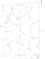
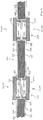
FIG. 3 depicts a cross-sectional view of the insulated core ofFIG. 2A , with the barrier film ofFIG. 2B disposed about the insulated core, and with the pair of pucks ofFIG. 1 disposed within the through bore of the insulated core; -
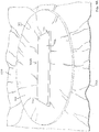
FIG. 4A depicts a perspective view of the insulated core ofFIG. 2A , with the barrier film ofFIG. 2B disposed about the insulated core, with the pair of pucks ofFIG. 1 disposed within the through bore of the insulated core, with the insulated core having been exposed to a vacuum, and with the barrier film having been heat-sealed about the insulated core; -
FIG. 4B depicts a perspective view of the insulated core ofFIG. 2A after being subjected to a vacuum and having the barrier film ofFIG. 2B heat-sealed about the insulated core, with the pair of pucks ofFIG. 1 removed from the through bore of the insulated core; -
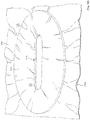
FIG. 4C depicts a perspective view of the insulated core ofFIG. 2A after being subjected to a vacuum and after having the barrier film ofFIG. 2B heat-sealed about the insulated core, with an excess of barrier film having been removed; -
FIG. 5 depicts a perspective view of one of a pair of circle-shaped pucks; -
FIG. 6 depicts a perspective view of one of a pair of trapezoid-shaped pucks; -
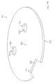
FIG. 7A depicts a perspective view of an insulated core having a pair of circle-shaped through bores and a trapezoid-shaped relief; -
FIG. 7B depicts a perspective view of the insulated core ofFIG. 7A with barrier film disposed about the insulated core; -
FIG. 7C depicts a perspective view of the insulated core ofFIG. 7A , with the barrier film ofFIG. 7B disposed about the insulated core, and with the pairs of pucks ofFIGS. 5 and 6 disposed within the through bores and relief of the insulated core; -
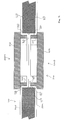
FIG. 8 depicts a cross-sectional view of the insulated core ofFIG. 7A , with the barrier film ofFIG. 7B disposed about the insulated core, and with the pairs of pucks ofFIGS. 5 and 6 disposed within the through bores and relief of the insulated core; -
FIG. 9 depicts another cross-sectional view of the insulated core ofFIG. 7A , with the barrier film ofFIG. 7B disposed about the insulated core, and with the pairs of pucks ofFIGS. 5 and 6 disposed within the through bores and relief of the insulated core; -
FIG. 10A depicts a perspective view of the insulated core ofFIG. 7A , with the barrier film ofFIG. 7B disposed about the insulated core, with the pairs of pucks ofFIGS. 5 and 6 disposed within the through bores and relief of the insulated core, with the insulated core having been exposed to a vacuum, and with the barrier film having been heat-sealed about the insulated core; -
FIG. 10B depicts a perspective view of the insulated core ofFIG. 7A after being subjected to a vacuum and after having the barrier film ofFIG. 7B heat-sealed about the insulated core, with the pairs pucks ofFIGS. 5 and 6 removed from the through bores and relief of the insulated core; and -
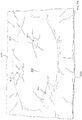
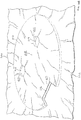
FIG. 10C depicts a perspective view of the insulated core ofFIG. 7A after being subjected to a vacuum and after having the barrier film ofFIG. 7B heat-sealed about the insulated core, with an excess of barrier film having been removed. - The drawings are not intended to be limiting in any way, and it is contemplated that various examples of the technology may be carried out in a variety of other ways, including those not necessarily depicted in the drawings. The accompanying drawings incorporated in and forming a part of the specification illustrate several aspects of the present technology, and together with the description serve to explain the principles of the technology; it being understood, however, that this technology is not limited to the precise arrangements shown.
- The following description of certain examples of the technology should not be used to limit its scope. Other examples, features, aspects and advantages of the technology will become apparent to those skilled in the art from the following description. As will be realized, the technology described herein is capable of other different and obvious aspects, all without departing from the technology. Accordingly, the drawings and descriptions should be regarded as illustrative in nature and not restrictive.
- It is further understood that any one or more of the teachings, expressions, examples, etc. described herein may be combined with any one or more of the other teachings, expressions, examples, etc. that are described herein. The following-described teachings, expressions, examples, etc. should therefore not be viewed in isolation relative to each other. Various suitable ways in which the teachings herein may be combined will be readily apparent to those of ordinary skill in the art in view of the teachings herein. Such modifications and variations are intended to be included within the scope of the claims.
- At least some of the devices and/or methods discussed below may be used to manufacture VIPs to be used in containers constructed in accordance with, or such VIPs discussed below may themselves be constructed and/or operable in accordance with, at least some of the teachings of
U.S. Pat. No. 7,913,511 ;U.S. Pat. No. 5,950,450 ;U.S. Pat. No. 5,943,876 ;U.S. Pat. No. 5,483,799 ;U.S. Pat. No. 5,603,220 ;U.S. Pat. No. 5,187,947 ;U.S. Pat. No. 6,860,115 ; and/orU.S. Pat. Pub. No. 2004/0226309 . It should be understood that the methods discussed below may used to manufacture VIPs to be used in, or such VIPs discussed below may themselves be constructed and/or operable in accordance with VIPs of the CSafe® RKN containers, the CSafe SVS containers, the CSafe AcuTemp AX27L containers, the CSafe AcuTemp AX56L containers, the CSafe AcuTemp Courier containers, the CSafe AcuTemp PX1L containers, or any other the CSafe packing container(s). Furthermore, the VIPs discussed below may have various structural and functional similarities with those taught in any of the other references that are cited herein. - An improved method of manufacturing VIPs includes the following steps. First, providing an insulated core having one or more through bores, cutouts, and/or reliefs (hereinafter generally referred to as "openings"). The insulated core may comprise microporous open cell silica aerogel, precipitated silica, fumed silica, glass fiber mats, ceramic fiber mats, and/or open-cell foam, but may comprise any other heat resistant insulating material. As will be understood from the discussion below, the insulated core and the openings formed therein may comprise any shape. A pair of barrier films are disposed about a top surface and a bottom surface of the insulated core to completely envelop the insulated core, including the opening formed therein, between the barrier films. Barrier films for use in VIPs are well-known in the art. The barrier films may comprise a multi-laminate oxygen and water vapor barrier film, but may comprise any other appropriate barrier material.
- With barrier films disposed about the insulated core, a first puck is positioned within the opening of the insulated core from a top side of the insulated core, and a second puck is positioned within the opening of the insulated core from a bottom side of the insulated core to thereby capture the barrier films between the pair of pucks. The pucks may comprise any material having sufficient rigidity, weight, and thermal resistance to withstand pressure, movement, and/or heat from "evacuating" and heat sealing the insulated core. As will be understood from the discussion below, it may be desirable to provide pucks with magnetic properties such that the pucks are attracted toward one another. The pucks may comprise a shape substantially similar to the shape of the opening of the insulated core, additionally or alternatively, the pucks may comprise protrusions having a shape substantially similar to the shape of the opening of the insulated core such that insertion of the pucks within the opening may compress the barrier films between the pair of pucks, between the pair of pucks and an interior surface of the opening, and/or between the pair of pucks and the top surface and the bottom surface of the insulated core. Compression of the barrier films in this manner is configured to minimize wrinkles and/or creases within the barrier films in these compressed areas.
- At this point, the insulated core is subjected to a vacuum to "evacuate" the insulated core of any gases within any void spaces of the insulated core to thereby reduce potential heat transfer across the insulated core. As the insulated core is subjected to a vacuum, the barrier films are heat sealed around the perimeter of the insulated core to thereby fluidly seal the insulated core in the evacuated state. This evacuation and/or heat sealing may cause wrinkles and/or creases in barrier films particularly around any opening, however, as discussed above, the pair of pucks are configured to minimize wrinkles and/or creases in the barrier films within the above discussed opening. The pucks are then removed from the opening, and the barrier film within the opening is heat sealed. Finally, excess material of the barrier films is then removed to thereby define a substantially wrinkle and/or crease free seal extending inwardly from the interior surface the opening.
-
FIGS. 1-4C illustrate an exemplary puck (100) and method of using puck (100) to manufacture VIPs to avoid wrinkling and/or creasing of a barrier film used to enclose an insulated core.FIG. 1 shows a puck (100) having a base (102) and an oblong-shaped protrusion (104) extending from a top surface (103) of base (102). Base (102) comprises a plurality of through bores (106). Although puck (100) of the present example comprises an oblong-shaped protrusion (104), it will be appreciated from the discussion below that puck (100) may comprise a protrusion having any other required shape (square, rectangular, triangular, etc.). -
FIGS. 2A-4C show the steps required to manufacture a VIP (130) using puck (100).FIG. 2A shows a circular-shaped insulated core (110) having an oblong-shaped through bore (112). Although insulated core (110) of the present example is circular-shaped, it should be understood that insulated core (110) may comprise any other required shape (square, rectangular, triangular, etc.). Also, although insulated core (110) of the present example comprises an oblong-shaped through bore (112), it will be appreciated from the discussion below that through bore (112) may comprise any other required shape (square, rectangular, triangular, etc.). As shown inFIG. 2B , a pair of barrier films (120, 122) are disposed adjacent to a top surface (114) and a bottom surface (116) of insulated core (110). - As shown in
FIGS. 2C and3 , with barrier films (120, 122) disposed adjacent to top surface (114) and bottom surface (116) of insulated core (110), a first puck (100A), constructed according to the above discussion regarding puck (100) but referred to as first puck (100A) for the sake of clarity, is positioned downwardly within through bore (112) such that top surface (103) of base (102) of first puck (100A) rests on or close to top surface (114) of insulated core (110) with barrier film (120) disposed there between. At the same time, a second puck (100B), constructed according to the above discussion regarding puck (100) but referred to as second puck (100B) for the sake of clarity, is positioned upwardly within through bore (112) such that bottom surface (116) of insulated core (110) rests on or close to top surface (103) of base (102) of second puck (100B) with barrier film (122) disposed there between. As shown inFIG. 3 , oblong-shaped protrusion (104) is sized such that with first puck (100A) and second puck (100B) disposed within through bore (112), barrier films (120, 122) are compressed between a top surface (107) of oblong-shaped protrusions (104) of pucks (100A, 100B). It should be appreciated that with barrier films (120, 122) compressed between top surfaces (107) of oblong-shaped protrusions (104) of pucks (100A, 100B), wrinkles and/or creases in barrier films (120, 122) will be minimized within this compressed area. - As shown in
FIG. 3 , oblong-shaped protrusions (104) of pucks (100A, 100B), and in general puck (100), may further be sized such that with pucks (100A, 100B) disposed within through bore (112) of insulated core (110), an exterior surface (105) of oblong-shaped protrusions (104) rests on or close to an interior surface (113) of through bore (112). Thus, with first puck (100A) and second puck (100B) disposed within through bore (112), exterior surfaces (105) of oblong-shaped protrusions (104) may compress barrier films (120, 122) between exterior surface (105) of oblong-shaped protrusions (104) and interior surface (113) of through bore (112) to thereby minimize wrinkles and/or creases in barrier films (120, 122) within this compressed area. - Also as shown in
FIG. 3 , oblong-shaped protrusions (104) of pucks (100A, 100B), and in general puck (100), may further be sized such that with pucks (100A, 100B) disposed within through bore (112) of insulated core (110), top surfaces (103) of bases (102) of pucks (100A, 100B) rest on or close to top surface (114) of insulated core (110) and bottom surface (116) of insulated core (110) respectively. Thus, with first puck (100A) and second puck (100B) disposed within through bore (112), top surfaces (103) of bases (102) of pucks (100A, 100B) may compress barrier films (120, 122) between top surfaces (103) of bases (102) and top surface (114) of insulated core (110) and bottom surface (116) of insulated core (110) to thereby minimize wrinkles and/or creases in barrier films (120, 122) within these compressed areas. - At this point, and as shown in
FIG. 4A , insulated core (110) is subjected to a vacuum to evacuate insulated core (110) of gases within any void spaces of insulated core (110) to thereby reduce heat transfer across insulated core (110). As insulated core (110) is subjected to a vacuum, barrier films (120, 122) are heat sealed to thereby fluidly seal insulated core (110) in the evacuated state. This evacuation and heat sealing may cause wrinkles and/or creases in barrier films (120, 122), however, as discussed above, pucks (100A, 100B) are configured to minimize wrinkles and/or creases in barrier films (120, 122) within the above discussed compressed areas. Pucks (100A, 100B) are then removed from through bore (112) as shown inFIG. 4B , and barrier films (120, 122) within through bore (112) are heat sealed to thereby form a fluid seal within through bore (112). Finally, excess material of barrier films (120, 122) is then removed to thereby define a seal (124) extending inwardly from interior surface (113) of through bore (112) and a seal (126) extending outwardly from insulated core (110) as shown inFIG. 4C . -
FIGS. 5-10C illustrate a pair of exemplary alternative pucks (200, 300) and a method of using pucks (200, 300) to manufacture VIPs to avoid wrinkling and/or creasing of a barrier film used to enclose an insulated core.FIG. 5 shows a puck (200) having a base (202) and a circular-shaped protrusion (204) extending from a top surface (203) of base (202). Base (202) comprises a plurality of through bores (206). Although puck (200) of the present example comprises a circular-shaped protrusion (204), it will be appreciated from the discussion below that puck (200) may comprise a protrusion having any other required shape (square, rectangular, triangular, etc.).FIG. 6 shows a puck (300) having a base (302) and a partial trapezoid-shaped protrusion (304) extending from a top surface (303) of base (302). Base (302) comprises a plurality of through bores (306). Although puck (300) of the present example comprises a trapezoid-shaped protrusion (304), it will be appreciated from the discussion below that puck (300) may comprise a protrusion having any other required shape (square, rectangular, triangular, etc.). -
FIGS. 7A-10C show the steps required to manufacture a VIP (230) using pucks (200, 300).FIG. 7A shows a circular-shaped insulated core (210) having a pair of circular-shaped through bores (212, 214). Although insulated core (210) of the present example is circular-shaped, it should be understood that insulated core (210) may comprise any other required shape (square, rectangular, triangular, etc.). Also, although insulated core (210) of the present example comprises a pair of circular-shaped through bores (212, 214), it will be appreciated from the discussion below that through bores (212, 214) may comprise any other required shape (square, rectangular, triangular, etc.). Circular-shaped insulated core (210) further comprises a trapezoid-shaped relief (216). Although insulated core (210) of the present example comprises a trapezoid-shaped relief (216), it will be appreciated from the discussion below that relief (216) may comprise any other required shape (square, rectangular, triangular, etc.). As shown inFIG. 7B , a pair of barrier films (220, 222) are disposed adjacent to a top surface (218) and a bottom surface (219) of insulated core (210). - As shown in
FIGS. 7C and8 , with barrier films (220, 222) disposed adjacent to top surface (218) and bottom surface (219) of insulated core (210), a first puck (200A), constructed according to the above discussion regarding puck (200) but referred to as first puck (200A) for the sake of clarity, is positioned downwardly within through bore (212) such that top surface (203) of base (202) of first puck (200A) rests on or close to top surface (218) of insulated core (210) with barrier film (220) disposed there between. A second puck (200B), constructed according to the above discussion regarding puck (200) but referred to as second puck (200B) for the sake of clarity, is positioned upwardly within through bore (212) such that bottom surface (219) of insulated core (210) rests no or close to top surface (203) of base (202) of second puck (200B) with barrier film (222) disposed there between. At the same time, a third puck (200C), constructed according to the above discussion regarding puck (200) but referred to as third puck (200C) for the sake of clarity, is positioned downwardly within through bore (214) such that top surface (203) of base (202) of third puck (200C) rests on or close to top surface (218) of insulated core (210) with barrier film (220) disposed there between. A fourth puck (200D), constructed according to the above discussion regarding puck (200) but referred to as fourth puck (200D) for the sake of clarity, is positioned upwardly within through bore (214) such that bottom surface (219) of insulated core (210) rests on or close to top surface (203) of base (202) of fourth puck (200D) with barrier film (222) disposed there between. - As shown in
FIG. 8 , circular-shaped protrusion (204) is sized such that with first puck (200A) and second puck (200B) disposed within through bore (212), and with third puck (200C) and fourth puck (200D) disposed within through bore (214), barrier films (220, 222) are compressed between top surfaces (207) of circular-shaped protrusions (204) of pucks (200A, 200B, 200C, 200D). It should be appreciated that with barrier films (220, 222) compressed between top surfaces (207) of circular-shaped protrusions (204) of pucks (200A, 200B, 200C, 200D), wrinkles and/or creases in barrier films (220, 222) will be minimized within this compressed area. - As shown in
FIG. 8 , circular-shaped protrusions (204) of pucks (200A, 200B, 200C, 200D), and in general puck (200), may further be sized such that with pucks (200A, 200B, 200C, 200D) disposed within through bores (212, 214) of insulated core (210), an exterior surface (204) of circular-shaped protrusions (204) rests on or close to an interior surface (213) of through bore (212) and an interior surface (215) of through bore (214). Thus, with first puck (200A) and second puck (200B) disposed within through bore (212), and with third puck (200C) and fourth puck (200D) disposed within through bore (214), exterior surfaces (205) of circular-shaped protrusions (204) may compress barrier films (220, 222) between exterior surface (205) of circular-shaped protrusions (204) and interior surfaces (213, 215) of through bores (212, 214) to thereby minimize wrinkles and/or creases in barrier films (120, 122) within this compressed area. - Also as shown in
FIG. 8 , circular-shaped protrusions (204) of pucks (200A, 200B, 200C, 200D), and in general puck (200), may further be sized such that with pucks (200A, 200B, 200C, 200D) disposed within through bores (212, 214) of insulated core (210), top surfaces (203) of bases (202) of pucks (200A, 200B, 200C, 200D) rest on or close to top surface (218) of insulated core (210) and bottom surface (219) of insulated core (210) respectively. Thus, with first puck (200A) and second puck (200B) disposed within through bore (212), and with third puck (200C) and fourth puck (200D) disposed within through bore (214), top surfaces (203) of bases (202) of pucks (200A, 200B, 200C, 200D) may compress barrier films (220, 222) between top surfaces (203) of bases (202) and top surface (218) of insulated core (210) and bottom surface (219) of insulated core (210) to thereby minimize wrinkles and/or creases in barrier films (220, 222) within these compressed areas. - As shown in
FIGS. 7C and9 , with barrier films (220, 222) disposed adjacent to top surface (218) and bottom surface (219) of insulated core (210), a first puck (300A), constructed according to the above discussion regarding puck (300) but referred to as first puck (300A) for the sake of clarity, is positioned downwardly within relief (216) such that top surface (303) of base (303) of first puck (300A) rests on or close to top surface (218) of insulated core (210) with barrier film (220) disposed there between. At the same time, a second puck (300B), constructed according to the above discussion regarding puck (300) but referred to as second puck (300B) for the sake of clarity, is positioned upwardly within relief (216) such that bottom surface (219) of insulated core (210) rests on or close to top surface (303) of base (302) of second puck (300B) with barrier film (222) disposed there between. As shown inFIG. 9 , trapezoid-shaped protrusion (304) is sized such that with first puck (300A) and second puck (300B) disposed within relief (216), barrier films (220, 222) are compressed between a top surface (307) of trapezoid-shaped protrusions (304) of pucks (300A, 300B). It should be appreciated that with barrier films (220, 222) compressed between top surfaces (307) of trapezoid-shaped protrusions (304) of pucks (300A, 300B), wrinkles and/or creases in barrier films (220, 222) will be minimized within this compressed area. - As shown in
FIG. 9 , trapezoid-shaped protrusions (304) of pucks (300A, 300B), and in general puck (300), may further be sized such that with pucks (300A, 300B) disposed within relief (216) of insulated core (210), an exterior surface (305) of trapezoid-shaped protrusions (304) rests on or close to an interior surface (217) of relief (216). Thus, with first puck (300A) and second puck (300B) disposed within relief (216), exterior surfaces (305) of trapezoid-shaped protrusions (304) may compress barrier films (220, 222) between exterior surface (305) of trapezoid-shaped protrusions (304) and interior surface (217) of relief (216) to thereby minimize wrinkles and/or creases in barrier films (220, 222) within this compressed area. - Also as shown in
FIG. 9 , trapezoid-shaped protrusions (304) of pucks (300A, 300B), and in general puck (300), may further be sized such that with pucks (300A, 300B) disposed within relief (216) of insulated core (210), top surfaces (303) of bases (302) of pucks (300A, 300B) rest on or close to top surface (218) of insulated core (210) and bottom surface (219) of insulated core (210) respectively. Thus, with first puck (300A) and second puck (300B) disposed within relief (216), top surfaces (303) of bases (302) of pucks (300A, 300B) may compress barrier films (220, 222) between top surfaces (303) of bases (302) and top surface (218) of insulated core (210) and bottom surface (219) of insulated core (210) to thereby minimize wrinkles and/or creases in barrier films (220, 222) within these compressed areas. - At this point, and as shown in
FIG. 10A , insulated core (210) is subjected to a vacuum to evacuate insulated core (210) of gases within any void spaces of insulated core (210) to thereby reduce heat transfer across insulated core (210). As insulated core (210) is subjected to a vacuum, barrier films (220, 222) are heat sealed to thereby fluidly seal insulated core (210) in the evacuated state. This evacuation and heat sealing may cause wrinkles and/or creases in barrier films (220, 222); however, as discussed above, pucks (200A, 200B, 200C, 200D, 300A, 300B) are configured to minimize wrinkles and/or creases in barrier films (220, 222) within the above discussed compressed areas. Pucks (200A, 200B, 200C, 200D, 300A, 300B) are then removed from through bores (212, 214) and relief (216) as shown inFIG. 10B , and barrier films (220, 222) within through bores (212, 214) and relief (216) are heat sealed to thereby form a fluid seal within through bores (212, 214) and relief (216). Finally, excess material of barrier films (220, 222) is then removed to thereby define a seal (224, 225) extending inwardly from interior surfaces (213, 215) of through bores (212, 214) and a seal (226) extending inwardly from interior surface (217) of relief (216) and outwardly from insulated core (210) as shown inFIG. 10C . - It should be understood that although the embodiments of pucks (100, 200, 300) discussed above were discussed as being used in pairs, it should be understood that in certain versions of VIPs (130, 230) it may be desirable to use pucks (100, 200, 300) singularly. For instance, although VIPs (130, 230) discussed above are described as comprising through bores (112, 212, 214) and/or relief (216) that pass completely through insulate cores (110, 210), it should be appreciated that a relief (not shown) may be formed in top surfaces (114, 218) and/or bottom surfaces (116, 219) of insulated cores (110, 210) that passes only partially through insulated cores (110, 210). A single puck (100, 200, 300) may then be positioned within this relief to thereby compress barrier film against a bottom surface and/or interior side surfaces of the relief to thereby minimize wrinkles and/or creases in the barrier film within this relief.
- Furthermore, protrusions (104, 204, 304) of pucks (100, 200, 300) may be sufficiently thick to pass completely through through bores (112, 212, 214) and/or relief (216) such that barrier film may be compressed between top surfaces (107, 207, 307) of protrusions (104, 204, 304) and a surface upon which insulated cores (110, 210) rest such that a single puck (100, 200, 300) may be used.
- Having shown and described various embodiments of the present invention, further adaptations of the systems described herein may be accomplished by appropriate modifications by one of ordinary skill in the art without departing from the scope of the present invention. Several of such potential modifications have been mentioned, and others will be apparent to those skilled in the art. For instance, the examples, embodiments, geometries, materials, dimensions, ratios, steps, and the like discussed above are illustrative and are not required. Accordingly, the scope of the present invention should be considered in terms of the following claims and is understood not to be limited to the details of structure and operation shown and described in the specification and drawings.
Claims (8)
- An apparatus for minimizing wrinkles and/or creases in barrier film of a vacuum insulated panel, the apparatus comprising:(a) a first puck (100A), wherein the first puck (100A) comprises:(i) a base (102), wherein the base (102) of the first puck comprises a top surface (103) and a bottom surface, and(ii) a protrusion (104), wherein the protrusion (104) of the first puck (100A) extends from the top surface (103) of the base (102) of the first puck (100A), wherein the protrusion (104) of the first puck (100A) comprises a top surface (107) and an exterior surface (105), wherein the exterior surface (105) of the protrusion (104) of the first puck (100A) defines a first shape; and(b) a second puck (100B), wherein the second puck (100B) comprises:(i) a base (102), wherein the base (102) of the second puck (100B) comprises a top surface (103) and a bottom surface, and(ii) a protrusion (104), wherein the protrusion (104) of the second puck (100B) extends from the top surface (103) of the base (102) of the second puck (100B), wherein the protrusion (104) of the second puck (100B) comprises a top surface (107) and an exterior surface (105), wherein the exterior surface (105) of the protrusion (104) of the second puck (100B) defines a second shape;
characterized in that
the first puck (100A) and the second puck (100B) are provided with magnetic properties such that the first puck (100a) and the second puck (100B) are attracted toward one another. - The apparatus of claim 1, wherein the first shape and the second shape comprise the same shape.
- The apparatus of claim 1, wherein the protrusion of the first puck and the protrusion of the second puck each define an interior void.
- The apparatus of claim 1, wherein the top surface of the base of the first puck and the top surface of the base of the second puck are configured to compress the at least one barrier film between the top surfaces and at least one other surface.
- The apparatus of claim 1, wherein the exterior surface of the protrusion of the first puck and the exterior surface of the protrusion of the second puck are configured to compress the at least one barrier film between the exterior surfaces and at least one other surface.
- The apparatus of claim 1, wherein the first shape and the second shape comprise an oblong.
- The apparatus of claim 1, wherein the first shape and the second shape comprise a circle.
- The apparatus of claim 1, wherein the first shape and the second shape comprise a partial trapezoid.
Applications Claiming Priority (2)
| Application Number | Priority Date | Filing Date | Title |
|---|---|---|---|
| US201361763537P | 2013-02-12 | 2013-02-12 | |
| EP14154915.4A EP2764999B1 (en) | 2013-02-12 | 2014-02-12 | Wrinkle free geometric opening in a vacuum insulated panel |
Related Parent Applications (2)
| Application Number | Title | Priority Date | Filing Date |
|---|---|---|---|
| EP14154915.4A Division EP2764999B1 (en) | 2013-02-12 | 2014-02-12 | Wrinkle free geometric opening in a vacuum insulated panel |
| EP14154915.4A Division-Into EP2764999B1 (en) | 2013-02-12 | 2014-02-12 | Wrinkle free geometric opening in a vacuum insulated panel |
Publications (2)
| Publication Number | Publication Date |
|---|---|
| EP3287278A1 EP3287278A1 (en) | 2018-02-28 |
| EP3287278B1 true EP3287278B1 (en) | 2020-04-08 |
Family
ID=50097597
Family Applications (2)
| Application Number | Title | Priority Date | Filing Date |
|---|---|---|---|
| EP17193528.1A Active EP3287278B1 (en) | 2013-02-12 | 2014-02-12 | Wrinkle free geometric opening in a vacuum insulated panel |
| EP14154915.4A Active EP2764999B1 (en) | 2013-02-12 | 2014-02-12 | Wrinkle free geometric opening in a vacuum insulated panel |
Family Applications After (1)
| Application Number | Title | Priority Date | Filing Date |
|---|---|---|---|
| EP14154915.4A Active EP2764999B1 (en) | 2013-02-12 | 2014-02-12 | Wrinkle free geometric opening in a vacuum insulated panel |
Country Status (2)
| Country | Link |
|---|---|
| US (3) | US9733006B2 (en) |
| EP (2) | EP3287278B1 (en) |
Families Citing this family (15)
| Publication number | Priority date | Publication date | Assignee | Title |
|---|---|---|---|---|
| US8986483B2 (en) | 2012-04-02 | 2015-03-24 | Whirlpool Corporation | Method of making a folded vacuum insulated structure |
| US9221210B2 (en) | 2012-04-11 | 2015-12-29 | Whirlpool Corporation | Method to create vacuum insulated cabinets for refrigerators |
| US9599392B2 (en) * | 2014-02-24 | 2017-03-21 | Whirlpool Corporation | Folding approach to create a 3D vacuum insulated door from 2D flat vacuum insulation panels |
| JP6207756B2 (en) * | 2014-09-09 | 2017-10-04 | 三菱電機株式会社 | Vacuum heat insulating material, manufacturing method of vacuum heat insulating material, installation structure of vacuum heat insulating material, and hot water storage tank equipped with vacuum heat insulating material |
| US10161669B2 (en) | 2015-03-05 | 2018-12-25 | Whirlpool Corporation | Attachment arrangement for vacuum insulated door |
| JP6735075B2 (en) * | 2015-08-28 | 2020-08-05 | シャープ株式会社 | refrigerator |
| US10422569B2 (en) | 2015-12-21 | 2019-09-24 | Whirlpool Corporation | Vacuum insulated door construction |
| US10018406B2 (en) | 2015-12-28 | 2018-07-10 | Whirlpool Corporation | Multi-layer gas barrier materials for vacuum insulated structure |
| US10807298B2 (en) | 2015-12-29 | 2020-10-20 | Whirlpool Corporation | Molded gas barrier parts for vacuum insulated structure |
| US11247369B2 (en) | 2015-12-30 | 2022-02-15 | Whirlpool Corporation | Method of fabricating 3D vacuum insulated refrigerator structure having core material |
| CN108779950A (en) * | 2016-03-16 | 2018-11-09 | 利勃海尔-家用电器利恩茨有限责任公司 | Cooling and/or freezing equipment |
| US11009284B2 (en) | 2016-04-15 | 2021-05-18 | Whirlpool Corporation | Vacuum insulated refrigerator structure with three dimensional characteristics |
| DE202018106306U1 (en) | 2018-11-06 | 2018-11-13 | Va-Q-Tec Ag | Temperable container with vacuum insulation elements |
| US10907891B2 (en) | 2019-02-18 | 2021-02-02 | Whirlpool Corporation | Trim breaker for a structural cabinet that incorporates a structural glass contact surface |
| WO2021046491A1 (en) | 2019-09-05 | 2021-03-11 | Cold Chain Technologies, Llc | Shipping system for temperature-sensitive materials |
Family Cites Families (12)
| Publication number | Priority date | Publication date | Assignee | Title |
|---|---|---|---|---|
| US5187947A (en) | 1991-10-16 | 1993-02-23 | Doskocil Companies Incorporated | Wheel type freezer and method for rapid, low temperature freezing |
| US5483799A (en) | 1994-04-29 | 1996-01-16 | Dalto; Michael | Temperature regulated specimen transporter |
| US5603220A (en) | 1995-09-11 | 1997-02-18 | Cool Med L.L.C. | Electronically controlled container for storing temperature sensitive material |
| US5950450A (en) | 1996-06-12 | 1999-09-14 | Vacupanel, Inc. | Containment system for transporting and storing temperature-sensitive materials |
| US6881358B1 (en) * | 1999-07-06 | 2005-04-19 | Mems Optical Inc. | Mold apparatus and method |
| SE515742C2 (en) | 2000-02-11 | 2001-10-01 | Envirotainer Engineering Aktie | Air freight container, cooling unit for an air freight container and manufacturing process for an air freight container |
| US20040074208A1 (en) * | 2000-05-30 | 2004-04-22 | Advantek, Inc. | Vacuum insulation panels and method for making same |
| JP2004011861A (en) * | 2002-06-11 | 2004-01-15 | Matsushita Refrig Co Ltd | Vacuum heat insulating material, refrigerator, heat/cold insulating vessel, and electric kettle |
| US20040226309A1 (en) | 2003-02-17 | 2004-11-18 | Broussard Kenneth W. | Temperature controlled, pallet-sized shipping container |
| JP4576195B2 (en) * | 2004-10-12 | 2010-11-04 | 日立アプライアンス株式会社 | Vacuum heat insulating material, refrigerator using vacuum heat insulating material, and manufacturing method of vacuum heat insulating material. |
| JP2006118639A (en) * | 2004-10-22 | 2006-05-11 | Matsushita Electric Ind Co Ltd | Vacuum insulation, refrigerator, thermal insulation container and electric water heater |
| US7913511B2 (en) | 2005-06-08 | 2011-03-29 | Doubleday Acquisitions, Llc | Cargo container for transporting temperature sensitive items |
-
2014
- 2014-02-12 US US14/178,335 patent/US9733006B2/en active Active
- 2014-02-12 EP EP17193528.1A patent/EP3287278B1/en active Active
- 2014-02-12 EP EP14154915.4A patent/EP2764999B1/en active Active
-
2017
- 2017-07-10 US US15/645,373 patent/US10203143B2/en active Active
- 2017-07-21 US US15/656,124 patent/US10234188B2/en active Active
Non-Patent Citations (1)
| Title |
|---|
| None * |
Also Published As
| Publication number | Publication date |
|---|---|
| EP3287278A1 (en) | 2018-02-28 |
| US9733006B2 (en) | 2017-08-15 |
| EP2764999A2 (en) | 2014-08-13 |
| US10203143B2 (en) | 2019-02-12 |
| US20140311667A1 (en) | 2014-10-23 |
| US20170307279A1 (en) | 2017-10-26 |
| US10234188B2 (en) | 2019-03-19 |
| US20170321949A1 (en) | 2017-11-09 |
| EP2764999B1 (en) | 2017-11-29 |
| EP2764999A3 (en) | 2014-11-12 |
Similar Documents
| Publication | Publication Date | Title |
|---|---|---|
| US10234188B2 (en) | Wrinkle free geometric opening in a vacuum insulated panel | |
| US9400133B2 (en) | Vacuum insulation material and heat insulation housing using the same | |
| CN104870881B (en) | Vacuum heat insulating material, heat insulating box having same, and manufacturing method of vacuum heat insulating material | |
| EP1291300A2 (en) | Multi-layer core for vacuum insulation panel and insulated container including a vacuum insulation panel | |
| CN108368963A (en) | Vacuum heat insulator, the manufacturing method with its heat insulation device and vacuum heat insulator | |
| JP2011102622A (en) | Insulating container | |
| JP5571610B2 (en) | Vacuum insulation material manufacturing method, vacuum insulation material and refrigerator equipped with the same | |
| JP6266162B2 (en) | Insulating body, vacuum heat insulating material, and method of manufacturing vacuum heat insulating material | |
| JP2015169372A (en) | Heat insulation container, and method of manufacturing heat insulation container | |
| US20170096284A1 (en) | Vacuum heat insulating body, and heat insulating container and heat insulating wall employing same | |
| EP4160075B1 (en) | Vacuum insulation material, and thermally insulating container and thermally insulating wall using same | |
| CN103998355B (en) | Vacuum insulation of integrated refrigerated containers | |
| AU2018412205B2 (en) | Vacuum heat insulating material and heat insulating box | |
| CN206347259U (en) | Vacuum heat insulator, heat insulating container and heat insulating wall using same | |
| CN108332002A (en) | Vacuum heat insulation materials, the manufacturing method of vacuum heat insulation materials and refrigerator | |
| CN206449358U (en) | Vacuum heat insulator, heat insulating container and heat insulating wall using the same | |
| JP6225324B2 (en) | Heat insulation box | |
| EP3284995A1 (en) | Vacuum heat insulator, and heat-insulating container and heat-insulating wall using same | |
| JP6609420B2 (en) | Vacuum insulation material and equipment using the same | |
| JP2013194761A (en) | Vacuum insulating material and heat insulation box body |
Legal Events
| Date | Code | Title | Description |
|---|---|---|---|
| PUAI | Public reference made under article 153(3) epc to a published international application that has entered the european phase |
Free format text: ORIGINAL CODE: 0009012 |
|
| STAA | Information on the status of an ep patent application or granted ep patent |
Free format text: STATUS: THE APPLICATION HAS BEEN PUBLISHED |
|
| AC | Divisional application: reference to earlier application |
Ref document number: 2764999 Country of ref document: EP Kind code of ref document: P |
|
| AK | Designated contracting states |
Kind code of ref document: A1 Designated state(s): AL AT BE BG CH CY CZ DE DK EE ES FI FR GB GR HR HU IE IS IT LI LT LU LV MC MK MT NL NO PL PT RO RS SE SI SK SM TR |
|
| STAA | Information on the status of an ep patent application or granted ep patent |
Free format text: STATUS: REQUEST FOR EXAMINATION WAS MADE |
|
| 17P | Request for examination filed |
Effective date: 20180828 |
|
| RBV | Designated contracting states (corrected) |
Designated state(s): AL AT BE BG CH CY CZ DE DK EE ES FI FR GB GR HR HU IE IS IT LI LT LU LV MC MK MT NL NO PL PT RO RS SE SI SK SM TR |
|
| STAA | Information on the status of an ep patent application or granted ep patent |
Free format text: STATUS: EXAMINATION IS IN PROGRESS |
|
| 17Q | First examination report despatched |
Effective date: 20181130 |
|
| RIC1 | Information provided on ipc code assigned before grant |
Ipc: E04B 1/80 20060101ALN20190710BHEP Ipc: F16L 59/06 20060101ALN20190710BHEP Ipc: B65D 81/38 20060101ALN20190710BHEP Ipc: B32B 37/18 20060101AFI20190710BHEP |
|
| GRAP | Despatch of communication of intention to grant a patent |
Free format text: ORIGINAL CODE: EPIDOSNIGR1 |
|
| STAA | Information on the status of an ep patent application or granted ep patent |
Free format text: STATUS: GRANT OF PATENT IS INTENDED |
|
| RIC1 | Information provided on ipc code assigned before grant |
Ipc: B65D 81/38 20060101ALN20191104BHEP Ipc: E04B 1/80 20060101ALN20191104BHEP Ipc: F16L 59/06 20060101ALN20191104BHEP Ipc: B32B 37/18 20060101AFI20191104BHEP |
|
| INTG | Intention to grant announced |
Effective date: 20191125 |
|
| GRAS | Grant fee paid |
Free format text: ORIGINAL CODE: EPIDOSNIGR3 |
|
| GRAA | (expected) grant |
Free format text: ORIGINAL CODE: 0009210 |
|
| STAA | Information on the status of an ep patent application or granted ep patent |
Free format text: STATUS: THE PATENT HAS BEEN GRANTED |
|
| AC | Divisional application: reference to earlier application |
Ref document number: 2764999 Country of ref document: EP Kind code of ref document: P |
|
| AK | Designated contracting states |
Kind code of ref document: B1 Designated state(s): AL AT BE BG CH CY CZ DE DK EE ES FI FR GB GR HR HU IE IS IT LI LT LU LV MC MK MT NL NO PL PT RO RS SE SI SK SM TR |
|
| REG | Reference to a national code |
Ref country code: AT Ref legal event code: REF Ref document number: 1253824 Country of ref document: AT Kind code of ref document: T Effective date: 20200415 Ref country code: CH Ref legal event code: EP |
|
| REG | Reference to a national code |
Ref country code: DE Ref legal event code: R096 Ref document number: 602014063685 Country of ref document: DE |
|
| REG | Reference to a national code |
Ref country code: IE Ref legal event code: FG4D |
|
| REG | Reference to a national code |
Ref country code: SE Ref legal event code: TRGR |
|
| REG | Reference to a national code |
Ref country code: NL Ref legal event code: MP Effective date: 20200408 |
|
| REG | Reference to a national code |
Ref country code: LT Ref legal event code: MG4D |
|
| PG25 | Lapsed in a contracting state [announced via postgrant information from national office to epo] |
Ref country code: LT Free format text: LAPSE BECAUSE OF FAILURE TO SUBMIT A TRANSLATION OF THE DESCRIPTION OR TO PAY THE FEE WITHIN THE PRESCRIBED TIME-LIMIT Effective date: 20200408 Ref country code: NL Free format text: LAPSE BECAUSE OF FAILURE TO SUBMIT A TRANSLATION OF THE DESCRIPTION OR TO PAY THE FEE WITHIN THE PRESCRIBED TIME-LIMIT Effective date: 20200408 Ref country code: NO Free format text: LAPSE BECAUSE OF FAILURE TO SUBMIT A TRANSLATION OF THE DESCRIPTION OR TO PAY THE FEE WITHIN THE PRESCRIBED TIME-LIMIT Effective date: 20200708 Ref country code: IS Free format text: LAPSE BECAUSE OF FAILURE TO SUBMIT A TRANSLATION OF THE DESCRIPTION OR TO PAY THE FEE WITHIN THE PRESCRIBED TIME-LIMIT Effective date: 20200808 Ref country code: GR Free format text: LAPSE BECAUSE OF FAILURE TO SUBMIT A TRANSLATION OF THE DESCRIPTION OR TO PAY THE FEE WITHIN THE PRESCRIBED TIME-LIMIT Effective date: 20200709 Ref country code: FI Free format text: LAPSE BECAUSE OF FAILURE TO SUBMIT A TRANSLATION OF THE DESCRIPTION OR TO PAY THE FEE WITHIN THE PRESCRIBED TIME-LIMIT Effective date: 20200408 Ref country code: PT Free format text: LAPSE BECAUSE OF FAILURE TO SUBMIT A TRANSLATION OF THE DESCRIPTION OR TO PAY THE FEE WITHIN THE PRESCRIBED TIME-LIMIT Effective date: 20200817 |
|
| REG | Reference to a national code |
Ref country code: AT Ref legal event code: MK05 Ref document number: 1253824 Country of ref document: AT Kind code of ref document: T Effective date: 20200408 |
|
| PG25 | Lapsed in a contracting state [announced via postgrant information from national office to epo] |
Ref country code: LV Free format text: LAPSE BECAUSE OF FAILURE TO SUBMIT A TRANSLATION OF THE DESCRIPTION OR TO PAY THE FEE WITHIN THE PRESCRIBED TIME-LIMIT Effective date: 20200408 Ref country code: HR Free format text: LAPSE BECAUSE OF FAILURE TO SUBMIT A TRANSLATION OF THE DESCRIPTION OR TO PAY THE FEE WITHIN THE PRESCRIBED TIME-LIMIT Effective date: 20200408 Ref country code: RS Free format text: LAPSE BECAUSE OF FAILURE TO SUBMIT A TRANSLATION OF THE DESCRIPTION OR TO PAY THE FEE WITHIN THE PRESCRIBED TIME-LIMIT Effective date: 20200408 Ref country code: BG Free format text: LAPSE BECAUSE OF FAILURE TO SUBMIT A TRANSLATION OF THE DESCRIPTION OR TO PAY THE FEE WITHIN THE PRESCRIBED TIME-LIMIT Effective date: 20200708 |
|
| PG25 | Lapsed in a contracting state [announced via postgrant information from national office to epo] |
Ref country code: AL Free format text: LAPSE BECAUSE OF FAILURE TO SUBMIT A TRANSLATION OF THE DESCRIPTION OR TO PAY THE FEE WITHIN THE PRESCRIBED TIME-LIMIT Effective date: 20200408 |
|
| REG | Reference to a national code |
Ref country code: DE Ref legal event code: R097 Ref document number: 602014063685 Country of ref document: DE |
|
| PG25 | Lapsed in a contracting state [announced via postgrant information from national office to epo] |
Ref country code: RO Free format text: LAPSE BECAUSE OF FAILURE TO SUBMIT A TRANSLATION OF THE DESCRIPTION OR TO PAY THE FEE WITHIN THE PRESCRIBED TIME-LIMIT Effective date: 20200408 Ref country code: CZ Free format text: LAPSE BECAUSE OF FAILURE TO SUBMIT A TRANSLATION OF THE DESCRIPTION OR TO PAY THE FEE WITHIN THE PRESCRIBED TIME-LIMIT Effective date: 20200408 Ref country code: EE Free format text: LAPSE BECAUSE OF FAILURE TO SUBMIT A TRANSLATION OF THE DESCRIPTION OR TO PAY THE FEE WITHIN THE PRESCRIBED TIME-LIMIT Effective date: 20200408 Ref country code: SM Free format text: LAPSE BECAUSE OF FAILURE TO SUBMIT A TRANSLATION OF THE DESCRIPTION OR TO PAY THE FEE WITHIN THE PRESCRIBED TIME-LIMIT Effective date: 20200408 Ref country code: IT Free format text: LAPSE BECAUSE OF FAILURE TO SUBMIT A TRANSLATION OF THE DESCRIPTION OR TO PAY THE FEE WITHIN THE PRESCRIBED TIME-LIMIT Effective date: 20200408 Ref country code: DK Free format text: LAPSE BECAUSE OF FAILURE TO SUBMIT A TRANSLATION OF THE DESCRIPTION OR TO PAY THE FEE WITHIN THE PRESCRIBED TIME-LIMIT Effective date: 20200408 Ref country code: ES Free format text: LAPSE BECAUSE OF FAILURE TO SUBMIT A TRANSLATION OF THE DESCRIPTION OR TO PAY THE FEE WITHIN THE PRESCRIBED TIME-LIMIT Effective date: 20200408 Ref country code: AT Free format text: LAPSE BECAUSE OF FAILURE TO SUBMIT A TRANSLATION OF THE DESCRIPTION OR TO PAY THE FEE WITHIN THE PRESCRIBED TIME-LIMIT Effective date: 20200408 |
|
| PLBE | No opposition filed within time limit |
Free format text: ORIGINAL CODE: 0009261 |
|
| STAA | Information on the status of an ep patent application or granted ep patent |
Free format text: STATUS: NO OPPOSITION FILED WITHIN TIME LIMIT |
|
| PG25 | Lapsed in a contracting state [announced via postgrant information from national office to epo] |
Ref country code: SK Free format text: LAPSE BECAUSE OF FAILURE TO SUBMIT A TRANSLATION OF THE DESCRIPTION OR TO PAY THE FEE WITHIN THE PRESCRIBED TIME-LIMIT Effective date: 20200408 Ref country code: PL Free format text: LAPSE BECAUSE OF FAILURE TO SUBMIT A TRANSLATION OF THE DESCRIPTION OR TO PAY THE FEE WITHIN THE PRESCRIBED TIME-LIMIT Effective date: 20200408 |
|
| 26N | No opposition filed |
Effective date: 20210112 |
|
| PG25 | Lapsed in a contracting state [announced via postgrant information from national office to epo] |
Ref country code: SI Free format text: LAPSE BECAUSE OF FAILURE TO SUBMIT A TRANSLATION OF THE DESCRIPTION OR TO PAY THE FEE WITHIN THE PRESCRIBED TIME-LIMIT Effective date: 20200408 |
|
| PG25 | Lapsed in a contracting state [announced via postgrant information from national office to epo] |
Ref country code: MC Free format text: LAPSE BECAUSE OF FAILURE TO SUBMIT A TRANSLATION OF THE DESCRIPTION OR TO PAY THE FEE WITHIN THE PRESCRIBED TIME-LIMIT Effective date: 20200408 |
|
| REG | Reference to a national code |
Ref country code: BE Ref legal event code: MM Effective date: 20210228 |
|
| PG25 | Lapsed in a contracting state [announced via postgrant information from national office to epo] |
Ref country code: CH Free format text: LAPSE BECAUSE OF NON-PAYMENT OF DUE FEES Effective date: 20210228 Ref country code: LU Free format text: LAPSE BECAUSE OF NON-PAYMENT OF DUE FEES Effective date: 20210212 Ref country code: LI Free format text: LAPSE BECAUSE OF NON-PAYMENT OF DUE FEES Effective date: 20210228 |
|
| PG25 | Lapsed in a contracting state [announced via postgrant information from national office to epo] |
Ref country code: IE Free format text: LAPSE BECAUSE OF NON-PAYMENT OF DUE FEES Effective date: 20210212 |
|
| PG25 | Lapsed in a contracting state [announced via postgrant information from national office to epo] |
Ref country code: BE Free format text: LAPSE BECAUSE OF NON-PAYMENT OF DUE FEES Effective date: 20210228 |
|
| PG25 | Lapsed in a contracting state [announced via postgrant information from national office to epo] |
Ref country code: CY Free format text: LAPSE BECAUSE OF FAILURE TO SUBMIT A TRANSLATION OF THE DESCRIPTION OR TO PAY THE FEE WITHIN THE PRESCRIBED TIME-LIMIT Effective date: 20200408 |
|
| PG25 | Lapsed in a contracting state [announced via postgrant information from national office to epo] |
Ref country code: HU Free format text: LAPSE BECAUSE OF FAILURE TO SUBMIT A TRANSLATION OF THE DESCRIPTION OR TO PAY THE FEE WITHIN THE PRESCRIBED TIME-LIMIT; INVALID AB INITIO Effective date: 20140212 |
|
| PG25 | Lapsed in a contracting state [announced via postgrant information from national office to epo] |
Ref country code: MK Free format text: LAPSE BECAUSE OF FAILURE TO SUBMIT A TRANSLATION OF THE DESCRIPTION OR TO PAY THE FEE WITHIN THE PRESCRIBED TIME-LIMIT Effective date: 20200408 |
|
| PG25 | Lapsed in a contracting state [announced via postgrant information from national office to epo] |
Ref country code: MT Free format text: LAPSE BECAUSE OF FAILURE TO SUBMIT A TRANSLATION OF THE DESCRIPTION OR TO PAY THE FEE WITHIN THE PRESCRIBED TIME-LIMIT Effective date: 20200408 |
|
| PGFP | Annual fee paid to national office [announced via postgrant information from national office to epo] |
Ref country code: DE Payment date: 20250227 Year of fee payment: 12 |
|
| PGFP | Annual fee paid to national office [announced via postgrant information from national office to epo] |
Ref country code: SE Payment date: 20250227 Year of fee payment: 12 |
|
| PGFP | Annual fee paid to national office [announced via postgrant information from national office to epo] |
Ref country code: FR Payment date: 20250225 Year of fee payment: 12 |
|
| PGFP | Annual fee paid to national office [announced via postgrant information from national office to epo] |
Ref country code: GB Payment date: 20250227 Year of fee payment: 12 |
|
| PG25 | Lapsed in a contracting state [announced via postgrant information from national office to epo] |
Ref country code: TR Free format text: LAPSE BECAUSE OF FAILURE TO SUBMIT A TRANSLATION OF THE DESCRIPTION OR TO PAY THE FEE WITHIN THE PRESCRIBED TIME-LIMIT Effective date: 20200408 |