EP3287207A1 - Method of forming a tubular member - Google Patents
Method of forming a tubular member Download PDFInfo
- Publication number
- EP3287207A1 EP3287207A1 EP17190824.7A EP17190824A EP3287207A1 EP 3287207 A1 EP3287207 A1 EP 3287207A1 EP 17190824 A EP17190824 A EP 17190824A EP 3287207 A1 EP3287207 A1 EP 3287207A1
- Authority
- EP
- European Patent Office
- Prior art keywords
- forming
- rollers
- segment
- pair
- roll
- Prior art date
- Legal status (The legal status is an assumption and is not a legal conclusion. Google has not performed a legal analysis and makes no representation as to the accuracy of the status listed.)
- Withdrawn
Links
Images

Classifications
-
- B—PERFORMING OPERATIONS; TRANSPORTING
- B21—MECHANICAL METAL-WORKING WITHOUT ESSENTIALLY REMOVING MATERIAL; PUNCHING METAL
- B21D—WORKING OR PROCESSING OF SHEET METAL OR METAL TUBES, RODS OR PROFILES WITHOUT ESSENTIALLY REMOVING MATERIAL; PUNCHING METAL
- B21D53/00—Making other particular articles
- B21D53/16—Making other particular articles rings, e.g. barrel hoops
-
- B—PERFORMING OPERATIONS; TRANSPORTING
- B21—MECHANICAL METAL-WORKING WITHOUT ESSENTIALLY REMOVING MATERIAL; PUNCHING METAL
- B21D—WORKING OR PROCESSING OF SHEET METAL OR METAL TUBES, RODS OR PROFILES WITHOUT ESSENTIALLY REMOVING MATERIAL; PUNCHING METAL
- B21D5/00—Bending sheet metal along straight lines, e.g. to form simple curves
- B21D5/004—Bending sheet metal along straight lines, e.g. to form simple curves with program control
-
- B—PERFORMING OPERATIONS; TRANSPORTING
- B21—MECHANICAL METAL-WORKING WITHOUT ESSENTIALLY REMOVING MATERIAL; PUNCHING METAL
- B21D—WORKING OR PROCESSING OF SHEET METAL OR METAL TUBES, RODS OR PROFILES WITHOUT ESSENTIALLY REMOVING MATERIAL; PUNCHING METAL
- B21D5/00—Bending sheet metal along straight lines, e.g. to form simple curves
- B21D5/06—Bending sheet metal along straight lines, e.g. to form simple curves by drawing procedure making use of dies or forming-rollers, e.g. making profiles
- B21D5/10—Bending sheet metal along straight lines, e.g. to form simple curves by drawing procedure making use of dies or forming-rollers, e.g. making profiles for making tubes
- B21D5/12—Bending sheet metal along straight lines, e.g. to form simple curves by drawing procedure making use of dies or forming-rollers, e.g. making profiles for making tubes making use of forming-rollers
-
- B—PERFORMING OPERATIONS; TRANSPORTING
- B23—MACHINE TOOLS; METAL-WORKING NOT OTHERWISE PROVIDED FOR
- B23K—SOLDERING OR UNSOLDERING; WELDING; CLADDING OR PLATING BY SOLDERING OR WELDING; CUTTING BY APPLYING HEAT LOCALLY, e.g. FLAME CUTTING; WORKING BY LASER BEAM
- B23K26/00—Working by laser beam, e.g. welding, cutting or boring
- B23K26/20—Bonding
- B23K26/21—Bonding by welding
- B23K26/24—Seam welding
- B23K26/28—Seam welding of curved planar seams
- B23K26/282—Seam welding of curved planar seams of tube sections
-
- B—PERFORMING OPERATIONS; TRANSPORTING
- B23—MACHINE TOOLS; METAL-WORKING NOT OTHERWISE PROVIDED FOR
- B23K—SOLDERING OR UNSOLDERING; WELDING; CLADDING OR PLATING BY SOLDERING OR WELDING; CUTTING BY APPLYING HEAT LOCALLY, e.g. FLAME CUTTING; WORKING BY LASER BEAM
- B23K31/00—Processes relevant to this subclass, specially adapted for particular articles or purposes, but not covered by any single one of main groups B23K1/00 - B23K28/00
-
- B—PERFORMING OPERATIONS; TRANSPORTING
- B23—MACHINE TOOLS; METAL-WORKING NOT OTHERWISE PROVIDED FOR
- B23K—SOLDERING OR UNSOLDERING; WELDING; CLADDING OR PLATING BY SOLDERING OR WELDING; CUTTING BY APPLYING HEAT LOCALLY, e.g. FLAME CUTTING; WORKING BY LASER BEAM
- B23K31/00—Processes relevant to this subclass, specially adapted for particular articles or purposes, but not covered by any single one of main groups B23K1/00 - B23K28/00
- B23K31/02—Processes relevant to this subclass, specially adapted for particular articles or purposes, but not covered by any single one of main groups B23K1/00 - B23K28/00 relating to soldering or welding
- B23K31/027—Making tubes by soldering or welding
-
- G—PHYSICS
- G01—MEASURING; TESTING
- G01B—MEASURING LENGTH, THICKNESS OR SIMILAR LINEAR DIMENSIONS; MEASURING ANGLES; MEASURING AREAS; MEASURING IRREGULARITIES OF SURFACES OR CONTOURS
- G01B5/00—Measuring arrangements characterised by the use of mechanical techniques
- G01B5/02—Measuring arrangements characterised by the use of mechanical techniques for measuring length, width or thickness
- G01B5/06—Measuring arrangements characterised by the use of mechanical techniques for measuring length, width or thickness for measuring thickness
- G01B5/068—Measuring arrangements characterised by the use of mechanical techniques for measuring length, width or thickness for measuring thickness of objects while moving
-
- B—PERFORMING OPERATIONS; TRANSPORTING
- B23—MACHINE TOOLS; METAL-WORKING NOT OTHERWISE PROVIDED FOR
- B23K—SOLDERING OR UNSOLDERING; WELDING; CLADDING OR PLATING BY SOLDERING OR WELDING; CUTTING BY APPLYING HEAT LOCALLY, e.g. FLAME CUTTING; WORKING BY LASER BEAM
- B23K2103/00—Materials to be soldered, welded or cut
- B23K2103/02—Iron or ferrous alloys
- B23K2103/04—Steel or steel alloys
Definitions
- a method for roll-forming a tubular member includes providing a roll-forming machine having a pair of rollers and a forming roller adjacent the pair of rollers. Further, cutting a strip of sheet metal to form a segment having free leading and trailing ends extending between a predetermined length; feeding the segment between the pair rollers; calculating the thickness of the segment via feedback from the pair of rollers; automatically adjusting the position of the forming roller in response to the determined thickness of the segment; advancing the segment between the pair of rollers and against the forming roller to form an annulus; and forming a weld joint between the free ends.
Landscapes
- Engineering & Computer Science (AREA)
- Mechanical Engineering (AREA)
- Physics & Mathematics (AREA)
- Optics & Photonics (AREA)
- General Physics & Mathematics (AREA)
- Plasma & Fusion (AREA)
- Bending Of Plates, Rods, And Pipes (AREA)
Abstract
Description
- This invention relates generally to methods of forming tubular members, and more particularly to methods of rolling and welding tubular members.
- It is well known to form metal tubular members from flat sheet material by rolling a fixed length of the sheet material into a tubular form and then welding abutting ends of the rolled sheet to one another to formed a length-wise extending welded seam. However, in forming rolled tubular members, challenges remain in being able to form the tubular member having tightly controlled inner or outer diameter tolerances. Further, challenges remain in being able to form the tubular member having a purely cylindrical shape. Typically, a flat surface is formed immediately adjacent the welded seam, resulting from a small segment of the flat sheet material not being curled. Further yet, challenges remain in forming tightly controlled diameter tolerances due to inherent variation in the actual sheet material thickness due to thickness tolerances of the sheet material. Accordingly, the inner and/or outer diameter of formed with one sheet material thickness is generally different from the inner and/or outer diameter of another sheet material thickness. When these tolerances are critical to the performance of the tubular member and components associate therewith, the useful life of the tubular member and/or components can be reduced.
- A method of forming a tubular member from a generally flat piece of metal sheet material in accordance with invention overcomes the challenges discussed above, as well as others, which will be readily apparent to those possessing ordinary skill in the art of forming tubular members from metal sheet material.
- In accordance with one aspect of the invention, a method for roll-forming a tubular member is provided. The method includes providing a roll-forming machine having a pair of rollers and a forming roller adjacent the pair of rollers. Further, cutting a strip of sheet metal to form a segment having free leading and trailing ends extending between a predetermined length; feeding the segment between the pair rollers; calculating the thickness of the segment via feedback from the pair of rollers; automatically adjusting the position of the forming roller in response to the determined thickness of the segment; advancing the segment between the pair of rollers and against the forming roller to form an annulus; and forming a weld joint between the free ends.
- In accordance with another aspect of the invention, the method further includes blanking the sheet metal and forming the leading end of the segment having a predetermined radius of curvature corresponding to the radius of curvature of the annulus.
- In accordance with another aspect of the invention, the method further includes moving the forming roller to compensate for the thickness of the segment to provide the annulus with at least one of a predetermined inner diameter and/or outer diameter.
- In accordance with another aspect of the invention, a further method for roll-forming a tubular member is provided. The method includes providing a roll-forming machine having a pair of rollers and a forming roller adjacent the pair of rollers. Further, cutting a strip of sheet metal to form a segment having free leading and trailing ends extending between a predetermined length, wherein the cutting is performed by blanking the sheet metal and forming the leading end of the segment having a predetermined radius of curvature. Then, feeding and advancing the segment between the pair of rollers and against the forming roller to form an annulus and forming a weld joint between the free ends.
- These and other aspects, features and advantages of the present invention will become more readily appreciated when considered in connection with the following detailed description of presently preferred embodiments and best mode, appended claims and accompanying drawings, in which:
-
Figure 1 is a perspective view of a tubular member constructed in accordance with one aspect of the invention; -
Figure 2 is a cross-sectional view of the tubular member ofFigure 1 ; -
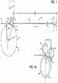
Figure 3 is a schematic side view of a segment of sheet metal being cut to length; -
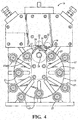
Figure 4 is a schematic front view of a rolling apparatus constructed in accordance with one aspect of the invention; and -
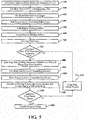
Figure 5 is a process flow chart of a process for forming a tubular member in accordance with one aspect of the invention. - Referring in more detail to the drawings,
Figure 1 illustrates atubular member 10, represented as an automatic transmission clutch apply ring, by way of example and without limitation, constructed in accordance with one presently preferred embodiment of the invention. The tubular member, referred to hereafter simply as annulus orring 10, is constructed from sheetmetal strip material 12, such as from steel, which is commonly supplied in coiled form. The steps used to form thering 10 illustrated inFigures 1 and 2 , by way of example, are shown in a process flow chart ofFigure 5 , which include the following steps: cuttingmetal sheet material 12 to a predetermined width to form an elongate strip of the material and optionally coiling thesheet material 100, and then, if coiled, uncoiling thecut strip material 12 and straightening thestrip material 200. Further, the straightenedstrip material 12 is processed in acutting operation 300 to form segments 14 having a predetermined length (I) sufficient to form the ring diameter desired. Then, the cut segments 14 are formed in arolling operation 400 by a servo-controlled roll-forming machine 16 (Figure 4 ) that produces the annular shape of thering 10. Further, thering 10 is pushed, such as via a hydraulic cylinder, for example, from theroll forming machine 16 to awelding station 500. Then, thering 10 is clamped in thewelding station 600 whereuponopposite ends ring 10 are welded to one another in awelding operation 700, such as via a laser welding operation, by way of example and without limitation. Then, the weld joint is check using feedback from aweld monitoring system 750 to verify that the weld joint meets specification. If the weld joint is flawed, thering 10 is then sent to scrap 775. However, if the weld joint meets specification, then thering 10 is ejected from the welding station, such as via a hydraulic cylinder, for example, and transferred to a sizing and flange spin-formingmachine 800. Further operations can then optionally be performed, depending on the intended application of thering 10, such as shown in steps 800-1400. For example, thering 10 can be ejected from the welding station and transferred to a sizing and flange spin-formingmachine 800, such as via a hydraulic cylinder, for example. Then, asizing process 900 can be performed on thering 10 to bring the ring to the precise size desired, such as via a hydraulic expanding mandrel. Further, thering 10 can be further processed via a spin-formingprocess 1000 to form a flange or flanges on outer edges of thering 10, such as via a servo-controlled spin device, for example. Then, thering 10 can be transferred to apiercing process 1100 and then notches and/or openings can be formed in a wall of thering 10, as desired. The processedring 10 is then inspected via asuitable ring gauge 1150, whereupon thering 10 is sent to scrap 1175 if failing inspection, or sent to finished product if passing inspection. Optionally, thering 10 can be further processed in a plating operation, if desired for the intended application. - The roll-forming
machine 16 has a pair ofrollers roller 26 adjacent the pair ofrollers machine 16 has a plurality ofrollers 27 separate from the pair ofrollers roller 26. The pair of rollers are provided as afeed roller 22 and apinch roller 24. Thefeed roller 22 is driven about afixed axle 28, while thepinch roller 24 rotates about anaxle 30 in response to engagement with the advancingstrip material 12. Theaxle 30 supporting thepinch roller 24 is movable toward and away from thefeed roller axle 28. In the roll-formingprocess 400, with the segment 14 ofstrip material 12 advanced to or slightly beyond atangent point 32 on thefeed roller 22, thepinch roller 24 is moved toward thefeed roller 22 into abutment with thestrip material 12 to a predetermined pressure. The pressure is determined via an electronic feedback loop, wherein the pressure and the distance of movement of thepinch roller 24 are used to automatically calculate the thickness (t) of the segment 14. Then, prior to forming thering 10, the formingroller 26 and the plurality ofrollers 27 are automatically moved along radially extending slots to a calculated radial position in response the calculated thickness (t) that results in forming the ring with a precise diameter (2 X R) desired. As such, any variability of the ring diameter that would otherwise result from thickness tolerances of the strip material are automatically accounted and adjusted for. The segment 14 is then advanced to abut atangent point 33 on the formingroller 26 and into abutment with the plurality ofrollers 27 to form the ring having a predetermined radius of curvature (R), whereupon theends welding process 700, whereupon further processing, e.g., spin forming, sizing, piercing, machining, and plating, for example, are then performed. - As shown in
Figure 3 , to facilitate forming thering 10 having a purely cylindrical wall, without any flat sections, the cutting operation forms aradiused end portion 34 of the segments 14 with a predetermined radius of curvature (r) via a cutting blade 36. Theradiused end portion 34 extends from thefree end 18 over a distance (d) equal to or slightly greater than a distance (D) between thetangent points feed roller 22 and forming roller 26 (Figures 4 and4A ). The predetermined radius of curvature (r) is provided having the same or substantially the same radius of curvature (R) as theannulus 10. As such, theend portion 34, which would tend to remain flat or substantially flat if not pre-curled upon forming thering 10, takes on a continuously curved radius of curvature r along with the remain portion of the segment 14, thereby providing thering 10 with a continuous radius of curvature R about its entire circumference. - The cutting blade 36 used in the blanking process has a leading
cutting edge 38 and a trailing cutting edge 40, with a radiused surface 42 extending therebetween. The radiused surface 42 has a radius r', which corresponds to (r + t), to produce theradiused end portion 34. To facilitate forming theradiused end portion 34, a mandrel 44 with an outercylindrical surface 46 with a radius r", being equal to or substantially equal to r, is used in combination with the cutting blade 36. The mandrel 44 underlies theend portion 34 of the segment 14 during blanking, such that as the cutting blade 36 blanks thestrip material 12, thestrip material 12 bends around theouter surface 46 of the mandrel 44. - Upon blanking the segment 14, the segment 14 is further processed as discussed above and as shown in the process flow chart of
Figure 5 . - Many modifications and variations of the present invention are possible in light of the above teachings. It is, therefore, to be understood that the invention may be practiced otherwise than as specifically described, and that the scope of the invention is defined by any ultimately allowed claims.
Claims (6)
- A method for roll-forming a tubular member, comprising:providing a roll-forming machine having a pair of rollers and a forming roller adjacent the pair of rollers;cutting a strip of sheet metal to form a segment having free leading and trailing ends extending between a predetermined length;feeding the segment between the pair rollers;advancing the segment between the pair of rollers and against the forming roller to form an annulus;forming a weld joint between the free ends; andperforming the cutting by a blanking the sheet metal and forming the leading end of the segment having a predetermined radius of curvature.
- The method of claim 1, further including forming the predetermined radius of curvature having substantially the same radius of curvature as the annulus.
- The method of claim 1, further including forming the predetermined radius extending over a distance substantially equal to the distance between tangent points of the pair of rollers and forming roller against which the segment abuts.
- The method of claim 1, further including calculating the thickness of the segment via feedback from the pair of rollers and automatically adjusting the position of the forming roller in response to the determined thickness.
- The method of claim 4, further including pinching the segment between the pair of rollers to a predetermined pressure.
- The method of claim 4, further including providing the roll-forming machine having a plurality of rollers separate from the pair of rollers and forming roller and automatically adjusting the position of the plurality of rollers in response to the determined thickness of the segment.
Applications Claiming Priority (2)
| Application Number | Priority Date | Filing Date | Title |
|---|---|---|---|
| US13/176,835 US9452464B2 (en) | 2011-07-06 | 2011-07-06 | Method of forming a tubular member |
| EP12737964.2A EP2729266B1 (en) | 2011-07-06 | 2012-07-03 | Method of forming a tubular member |
Related Parent Applications (1)
| Application Number | Title | Priority Date | Filing Date |
|---|---|---|---|
| EP12737964.2A Division EP2729266B1 (en) | 2011-07-06 | 2012-07-03 | Method of forming a tubular member |
Publications (1)
| Publication Number | Publication Date |
|---|---|
| EP3287207A1 true EP3287207A1 (en) | 2018-02-28 |
Family
ID=46548840
Family Applications (2)
| Application Number | Title | Priority Date | Filing Date |
|---|---|---|---|
| EP17190824.7A Withdrawn EP3287207A1 (en) | 2011-07-06 | 2012-07-03 | Method of forming a tubular member |
| EP12737964.2A Not-in-force EP2729266B1 (en) | 2011-07-06 | 2012-07-03 | Method of forming a tubular member |
Family Applications After (1)
| Application Number | Title | Priority Date | Filing Date |
|---|---|---|---|
| EP12737964.2A Not-in-force EP2729266B1 (en) | 2011-07-06 | 2012-07-03 | Method of forming a tubular member |
Country Status (3)
| Country | Link |
|---|---|
| US (2) | US9452464B2 (en) |
| EP (2) | EP3287207A1 (en) |
| WO (1) | WO2013006597A2 (en) |
Cited By (1)
| Publication number | Priority date | Publication date | Assignee | Title |
|---|---|---|---|---|
| US12233452B2 (en) | 2022-01-14 | 2025-02-25 | Rolls-Royce Plc | System and method for contouring ring component |
Families Citing this family (3)
| Publication number | Priority date | Publication date | Assignee | Title |
|---|---|---|---|---|
| JP6486695B2 (en) * | 2015-01-14 | 2019-03-20 | 浜松ホトニクス株式会社 | Bolometer type THz detector |
| US11219933B2 (en) * | 2017-11-10 | 2022-01-11 | Promau S.R.L. | Apparatus and method for support and controlled advancement of a metal sheet in a bending machine for obtaining cylindrical or truncated cone structures |
| CN110814108B (en) * | 2019-11-28 | 2020-11-10 | 磐安锐力五金有限公司 | A sheet metal rolling device |
Citations (4)
| Publication number | Priority date | Publication date | Assignee | Title |
|---|---|---|---|---|
| US4304114A (en) * | 1978-04-19 | 1981-12-08 | F. J. Littell Machine Company | Process of rolling automobile rims |
| US4549422A (en) * | 1983-04-29 | 1985-10-29 | Harrow Donald A | Cup and roll machine |
| US4706488A (en) * | 1984-05-16 | 1987-11-17 | Kaiser Steel Corporation | Method of roll forming cylindrical pipe |
| US7213431B1 (en) * | 2006-02-01 | 2007-05-08 | Evergreat Intl Co., Ltd. | Method of manufacturing an aluminum alloy wheel |
Family Cites Families (49)
| Publication number | Priority date | Publication date | Assignee | Title |
|---|---|---|---|---|
| US735936A (en) * | 1901-11-01 | 1903-08-11 | George G Blakey | Manufacture of tubular articles. |
| US928220A (en) * | 1908-08-21 | 1909-07-13 | Philadelphia Pipe Bending Company | Pipe-coiling machine. |
| US1043832A (en) | 1910-02-19 | 1912-11-12 | Fiber Barrel Machinery And Mfg Company | Machine for forming metal hoops. |
| US1507838A (en) | 1922-12-23 | 1924-09-09 | Krump Nic | Bending machine for angle irons |
| US2854743A (en) | 1955-02-21 | 1958-10-07 | Kelsey Hayes Co | Method of displacing and removing flash from a welded joint |
| US3129496A (en) | 1959-12-08 | 1964-04-21 | Darwin S Cox | Method of producing improved vehicle wheels |
| US3129505A (en) | 1961-05-09 | 1964-04-21 | Darwin S Cox | Process of manufacturing one piece brake drum shells |
| US3729124A (en) | 1971-04-05 | 1973-04-24 | Allegheny Ludlum Ind Inc | Apparatus for reducing the weld build-up on seam welded tubing |
| US3738149A (en) * | 1971-10-01 | 1973-06-12 | B Archer | Pipe forming apparatus and method |
| DE2253025C3 (en) * | 1972-10-28 | 1979-10-25 | Hoesch Maschinenfabrik Deutschland Ag, 4600 Dortmund | Device for the production of screw sutures |
| US4058997A (en) * | 1974-11-13 | 1977-11-22 | Emil Siegwart | Apparatus for manufacturing tubes |
| US3934324A (en) | 1975-02-14 | 1976-01-27 | Grotnes Machine Works, Inc. | Method and apparatus for forming automotive wheel rim blanks |
| US4010831A (en) * | 1975-11-21 | 1977-03-08 | General Motors Corporation | Transmission friction plate and device |
| JPS52142260A (en) * | 1976-05-24 | 1977-11-28 | Hitachi Ltd | Winding machine |
| US4082935A (en) | 1976-07-19 | 1978-04-04 | Torin Corporation | Apparatus and method for making wheel rim blanks and the like |
| US4249406A (en) * | 1978-09-05 | 1981-02-10 | Anderson Frohman C | Line pipe forming apparatus and method |
| DE3037614A1 (en) | 1980-10-04 | 1982-06-03 | Th. Kieserling & Albrecht Gmbh & Co, 5650 Solingen | SYSTEM FOR THE PRODUCTION OF WHEEL RIMS |
| JPS5775297A (en) | 1980-10-28 | 1982-05-11 | Topy Ind Ltd | Production of wheel rim |
| US4616495A (en) * | 1982-05-27 | 1986-10-14 | Rib Loc Hong Kong Limited | Helically-formed pipe winding machine |
| JPS59223116A (en) | 1983-06-03 | 1984-12-14 | Hitachi Ltd | Manufacturing equipment of electric welded tube |
| US4633698A (en) | 1983-12-21 | 1987-01-06 | Hans Oetiker | Method for preforming a substantially flat blank of an open clamp |
| US4634038A (en) | 1984-06-15 | 1987-01-06 | Caprioglio Luigi | Apparatus for the manufacture of ring members |
| JPS6178518A (en) * | 1984-09-21 | 1986-04-22 | Sumitomo Metal Mining Co Ltd | Roll adjustment device of roll forming machine |
| CH669130A5 (en) * | 1985-06-11 | 1989-02-28 | Elpatronic Ag | METHOD AND DEVICE FOR ROUNDING SHEETS, ESPECIALLY FOR CAN BODIES. |
| JPS629734A (en) | 1985-07-08 | 1987-01-17 | Toyota Motor Corp | Forming method for odd-shaped ring parts |
| DE227870T1 (en) * | 1985-12-30 | 1987-11-05 | Societe Nouvelle Des Ateliers Et Chantiers Du Havre, Le Havre | MACHINE FOR BENDING SHEETS WITH AUTOMATIC CONTROL. |
| CH669921A5 (en) | 1986-04-22 | 1989-04-28 | Elpatronic Ag | |
| JPH01138021A (en) * | 1987-11-24 | 1989-05-30 | Mitsubishi Electric Corp | Bending equipment for band steel |
| ATE120389T1 (en) * | 1990-09-28 | 1995-04-15 | Promau Srl | PROGRAMMABLE SHEET METAL BENDING MACHINE. |
| FR2673863B1 (en) | 1991-03-14 | 1995-05-19 | Snecma | PROCESS AND TOOLS FOR MANUFACTURING AN ANNULAR PART IN SHEET. |
| FR2687336B1 (en) | 1992-02-14 | 1996-05-15 | Jammes Ind Sa | AUTOMATED PRODUCTION LINE FOR WELDED ROLLED RODS. |
| JPH07185671A (en) | 1993-12-27 | 1995-07-25 | Daido Kikai Seisakusho:Kk | Roll bender |
| JPH07314050A (en) | 1994-05-30 | 1995-12-05 | Kuwahara Seisakusho:Kk | Roll forming method |
| US5609055A (en) * | 1995-03-20 | 1997-03-11 | Spiral-Helix, Inc. | Method and apparatus for cutting and notching a hollow pipe |
| DE19708488A1 (en) | 1997-03-03 | 1998-09-10 | Betr Forsch Inst Angew Forsch | Device for straightening metal strips |
| TW404856B (en) | 1997-03-28 | 2000-09-11 | Kawasaki Steel Co | Smoothing device on steel pipe seams and its manufacturing method |
| JPH1138021A (en) | 1997-07-18 | 1999-02-12 | Hitachi Constr Mach Co Ltd | Scanning probe microscope and approach mechanism thereof |
| US6588648B1 (en) | 1998-03-03 | 2003-07-08 | Elpatronic Ag | Method and device for transferring a hollow-profile blank |
| DE19820357C1 (en) | 1998-05-07 | 1999-10-07 | Roland Man Druckmasch | Method of welding seam in printer cylinder shell |
| TW449509B (en) | 1998-11-04 | 2001-08-11 | Kawasaki Steel Co | Bending rolls, and pipe formed thereby |
| JP3479503B2 (en) | 2000-08-29 | 2003-12-15 | 株式会社ミハル | Bent product, bending method and bending device used for the same |
| JP2003001329A (en) * | 2001-06-22 | 2003-01-07 | Fuji Industrial Co Ltd | Device for roll forming of cylindrical body having many parallel blades |
| JP2003311466A (en) | 2002-04-16 | 2003-11-05 | Honda Motor Co Ltd | Manufacturing method of annular body |
| US7124609B1 (en) * | 2002-09-04 | 2006-10-24 | Jeffrey Allen Hermanson | Spin forming of HVAC duct reducers |
| JP3904529B2 (en) * | 2003-03-31 | 2007-04-11 | 株式会社栗本鐵工所 | Pipe forming method and apparatus |
| US7131305B2 (en) | 2003-10-17 | 2006-11-07 | Delphi Technologies, Inc. | Method and apparatus for lean spin forming |
| US6990841B2 (en) | 2003-10-17 | 2006-01-31 | Delphi Technologies, Inc. | Method and apparatus for lean spin forming transition portions having various shapes |
| NL1026796C2 (en) | 2004-08-06 | 2006-02-07 | Fontijne Grotnes B V | Method and device for manufacturing a rim ring by means of cold deformation. |
| JP6174819B2 (en) * | 2013-09-30 | 2017-08-02 | エルジー・ケム・リミテッド | Heterocyclic compound and organic light emitting device using the same |
-
2011
- 2011-07-06 US US13/176,835 patent/US9452464B2/en not_active Expired - Fee Related
-
2012
- 2012-07-03 EP EP17190824.7A patent/EP3287207A1/en not_active Withdrawn
- 2012-07-03 EP EP12737964.2A patent/EP2729266B1/en not_active Not-in-force
- 2012-07-03 WO PCT/US2012/045351 patent/WO2013006597A2/en not_active Ceased
-
2016
- 2016-09-26 US US15/275,731 patent/US20170100765A1/en not_active Abandoned
Patent Citations (4)
| Publication number | Priority date | Publication date | Assignee | Title |
|---|---|---|---|---|
| US4304114A (en) * | 1978-04-19 | 1981-12-08 | F. J. Littell Machine Company | Process of rolling automobile rims |
| US4549422A (en) * | 1983-04-29 | 1985-10-29 | Harrow Donald A | Cup and roll machine |
| US4706488A (en) * | 1984-05-16 | 1987-11-17 | Kaiser Steel Corporation | Method of roll forming cylindrical pipe |
| US7213431B1 (en) * | 2006-02-01 | 2007-05-08 | Evergreat Intl Co., Ltd. | Method of manufacturing an aluminum alloy wheel |
Cited By (1)
| Publication number | Priority date | Publication date | Assignee | Title |
|---|---|---|---|---|
| US12233452B2 (en) | 2022-01-14 | 2025-02-25 | Rolls-Royce Plc | System and method for contouring ring component |
Also Published As
| Publication number | Publication date |
|---|---|
| US20130008218A1 (en) | 2013-01-10 |
| WO2013006597A3 (en) | 2013-04-25 |
| US20170100765A1 (en) | 2017-04-13 |
| WO2013006597A2 (en) | 2013-01-10 |
| EP2729266A2 (en) | 2014-05-14 |
| EP2729266B1 (en) | 2017-09-20 |
| US9452464B2 (en) | 2016-09-27 |
Similar Documents
| Publication | Publication Date | Title |
|---|---|---|
| US9452459B2 (en) | Method for manufacturing shaped steel the cross-sectional shape of which changes in the longitudinal direction, and roll forming device | |
| EP2531312B1 (en) | Unified rolling and bending process for roller bearing cages | |
| US9878360B2 (en) | Method of producing shaped steel changing in cross-sectional shape in longitudinal direction and roll forming apparatus for same | |
| US20170100765A1 (en) | Method of forming a tubular member | |
| EP3006128B1 (en) | Method of manufacturing a welded steel pipe | |
| US7918380B1 (en) | Method and apparatus for manufacturing welded tapered tubes | |
| KR101605888B1 (en) | Apparatus and method for manufacturing outer circumference ring | |
| US9782812B2 (en) | Method and apparatus for cutting openings in sidewall of spiral pipe | |
| US3540395A (en) | Method of slitting a continuous strip of metal and article formed therefrom | |
| US7107682B2 (en) | Method for manufacturing tubes and profiles | |
| EP3549689B1 (en) | Strip profiling line comprising a cutting device | |
| JP5893716B1 (en) | Separator apparatus, coil product manufacturing apparatus and manufacturing method | |
| JP2024507062A (en) | Method and system for forming tubular or frustoconical segments | |
| JP2019177395A (en) | Bending method and device of end of steel plate, manufacturing method of steel pipe, and equipment | |
| US20160136703A1 (en) | Method for producing annular parts and use of said method | |
| JP6913657B2 (en) | Multi-winding tube molding device and multi-winding tube molding method | |
| KR101526342B1 (en) | Manufacturing method and manufacturing equipment for small diameter metal tube | |
| US10035179B2 (en) | Apparatus and method for the continuous and progressive shaping of metal strips to give a profile with longitudinally varying cross section | |
| CN106470773B (en) | Method and apparatus for manufacturing tubular insulating elements of sheet metal | |
| JPH05277559A (en) | Correcting method for welded metallic tube | |
| JP2006192448A (en) | Method for manufacturing flat ring member | |
| JP2002210504A (en) | Ring rolling rolling method and apparatus | |
| KR20160116095A (en) | Roll forming method and apparatus for machining parts | |
| CN210936513U (en) | Guiding device for welded steel pipe | |
| TW201515728A (en) | Manufacturing method for section steel of variable cross-sectional shapes in longitudinal direction, and roll forming device |
Legal Events
| Date | Code | Title | Description |
|---|---|---|---|
| PUAI | Public reference made under article 153(3) epc to a published international application that has entered the european phase |
Free format text: ORIGINAL CODE: 0009012 |
|
| STAA | Information on the status of an ep patent application or granted ep patent |
Free format text: STATUS: THE APPLICATION HAS BEEN PUBLISHED |
|
| AC | Divisional application: reference to earlier application |
Ref document number: 2729266 Country of ref document: EP Kind code of ref document: P |
|
| AK | Designated contracting states |
Kind code of ref document: A1 Designated state(s): AL AT BE BG CH CY CZ DE DK EE ES FI FR GB GR HR HU IE IS IT LI LT LU LV MC MK MT NL NO PL PT RO RS SE SI SK SM TR |
|
| STAA | Information on the status of an ep patent application or granted ep patent |
Free format text: STATUS: REQUEST FOR EXAMINATION WAS MADE |
|
| 17P | Request for examination filed |
Effective date: 20180411 |
|
| RBV | Designated contracting states (corrected) |
Designated state(s): AL AT BE BG CH CY CZ DE DK EE ES FI FR GB GR HR HU IE IS IT LI LT LU LV MC MK MT NL NO PL PT RO RS SE SI SK SM TR |
|
| STAA | Information on the status of an ep patent application or granted ep patent |
Free format text: STATUS: THE APPLICATION IS DEEMED TO BE WITHDRAWN |
|
| 18D | Application deemed to be withdrawn |
Effective date: 20200201 |