EP3287093A1 - Medizinisches instrumentarium und verfahren - Google Patents
Medizinisches instrumentarium und verfahren Download PDFInfo
- Publication number
- EP3287093A1 EP3287093A1 EP17187063.7A EP17187063A EP3287093A1 EP 3287093 A1 EP3287093 A1 EP 3287093A1 EP 17187063 A EP17187063 A EP 17187063A EP 3287093 A1 EP3287093 A1 EP 3287093A1
- Authority
- EP
- European Patent Office
- Prior art keywords
- article
- marking device
- shape
- navigation system
- data processing
- Prior art date
- Legal status (The legal status is an assumption and is not a legal conclusion. Google has not performed a legal analysis and makes no representation as to the accuracy of the status listed.)
- Granted
Links
Images


Classifications
-
- A—HUMAN NECESSITIES
- A61—MEDICAL OR VETERINARY SCIENCE; HYGIENE
- A61B—DIAGNOSIS; SURGERY; IDENTIFICATION
- A61B17/00—Surgical instruments, devices or methods
- A61B17/56—Surgical instruments or methods for treatment of bones or joints; Devices specially adapted therefor
- A61B17/58—Surgical instruments or methods for treatment of bones or joints; Devices specially adapted therefor for osteosynthesis, e.g. bone plates, screws or setting implements
- A61B17/68—Internal fixation devices, including fasteners and spinal fixators, even if a part thereof projects from the skin
- A61B17/70—Spinal positioners or stabilisers, e.g. stabilisers comprising fluid filler in an implant
- A61B17/7074—Tools specially adapted for spinal fixation operations other than for bone removal or filler handling
- A61B17/7083—Tools for guidance or insertion of tethers, rod-to-anchor connectors, rod-to-rod connectors, or longitudinal elements
-
- A—HUMAN NECESSITIES
- A61—MEDICAL OR VETERINARY SCIENCE; HYGIENE
- A61B—DIAGNOSIS; SURGERY; IDENTIFICATION
- A61B17/00—Surgical instruments, devices or methods
- A61B17/56—Surgical instruments or methods for treatment of bones or joints; Devices specially adapted therefor
- A61B17/58—Surgical instruments or methods for treatment of bones or joints; Devices specially adapted therefor for osteosynthesis, e.g. bone plates, screws or setting implements
- A61B17/68—Internal fixation devices, including fasteners and spinal fixators, even if a part thereof projects from the skin
- A61B17/84—Fasteners therefor or fasteners being internal fixation devices
-
- A—HUMAN NECESSITIES
- A61—MEDICAL OR VETERINARY SCIENCE; HYGIENE
- A61B—DIAGNOSIS; SURGERY; IDENTIFICATION
- A61B17/00—Surgical instruments, devices or methods
- A61B17/56—Surgical instruments or methods for treatment of bones or joints; Devices specially adapted therefor
- A61B17/58—Surgical instruments or methods for treatment of bones or joints; Devices specially adapted therefor for osteosynthesis, e.g. bone plates, screws or setting implements
- A61B17/88—Osteosynthesis instruments; Methods or means for implanting or extracting internal or external fixation devices
- A61B17/8863—Apparatus for shaping or cutting osteosynthesis equipment by medical personnel
-
- A—HUMAN NECESSITIES
- A61—MEDICAL OR VETERINARY SCIENCE; HYGIENE
- A61B—DIAGNOSIS; SURGERY; IDENTIFICATION
- A61B34/00—Computer-aided surgery; Manipulators or robots specially adapted for use in surgery
- A61B34/20—Surgical navigation systems; Devices for tracking or guiding surgical instruments, e.g. for frameless stereotaxis
-
- A—HUMAN NECESSITIES
- A61—MEDICAL OR VETERINARY SCIENCE; HYGIENE
- A61F—FILTERS IMPLANTABLE INTO BLOOD VESSELS; PROSTHESES; DEVICES PROVIDING PATENCY TO, OR PREVENTING COLLAPSING OF, TUBULAR STRUCTURES OF THE BODY, e.g. STENTS; ORTHOPAEDIC, NURSING OR CONTRACEPTIVE DEVICES; FOMENTATION; TREATMENT OR PROTECTION OF EYES OR EARS; BANDAGES, DRESSINGS OR ABSORBENT PADS; FIRST-AID KITS
- A61F2/00—Filters implantable into blood vessels; Prostheses, i.e. artificial substitutes or replacements for parts of the body; Appliances for connecting them with the body; Devices providing patency to, or preventing collapsing of, tubular structures of the body, e.g. stents
- A61F2/02—Prostheses implantable into the body
- A61F2/30—Joints
- A61F2/44—Joints for the spine, e.g. vertebrae, spinal discs
- A61F2/4455—Joints for the spine, e.g. vertebrae, spinal discs for the fusion of spinal bodies, e.g. intervertebral fusion of adjacent spinal bodies, e.g. fusion cages
-
- A—HUMAN NECESSITIES
- A61—MEDICAL OR VETERINARY SCIENCE; HYGIENE
- A61B—DIAGNOSIS; SURGERY; IDENTIFICATION
- A61B34/00—Computer-aided surgery; Manipulators or robots specially adapted for use in surgery
- A61B34/20—Surgical navigation systems; Devices for tracking or guiding surgical instruments, e.g. for frameless stereotaxis
- A61B2034/2046—Tracking techniques
- A61B2034/2055—Optical tracking systems
-
- A—HUMAN NECESSITIES
- A61—MEDICAL OR VETERINARY SCIENCE; HYGIENE
- A61B—DIAGNOSIS; SURGERY; IDENTIFICATION
- A61B34/00—Computer-aided surgery; Manipulators or robots specially adapted for use in surgery
- A61B34/20—Surgical navigation systems; Devices for tracking or guiding surgical instruments, e.g. for frameless stereotaxis
- A61B2034/2046—Tracking techniques
- A61B2034/2055—Optical tracking systems
- A61B2034/2057—Details of tracking cameras
-
- A—HUMAN NECESSITIES
- A61—MEDICAL OR VETERINARY SCIENCE; HYGIENE
- A61B—DIAGNOSIS; SURGERY; IDENTIFICATION
- A61B90/00—Instruments, implements or accessories specially adapted for surgery or diagnosis and not covered by any of the groups A61B1/00 - A61B50/00, e.g. for luxation treatment or for protecting wound edges
- A61B90/30—Devices for illuminating a surgical field, the devices having an interrelation with other surgical devices or with a surgical procedure
- A61B2090/309—Devices for illuminating a surgical field, the devices having an interrelation with other surgical devices or with a surgical procedure using white LEDs
-
- A—HUMAN NECESSITIES
- A61—MEDICAL OR VETERINARY SCIENCE; HYGIENE
- A61B—DIAGNOSIS; SURGERY; IDENTIFICATION
- A61B90/00—Instruments, implements or accessories specially adapted for surgery or diagnosis and not covered by any of the groups A61B1/00 - A61B50/00, e.g. for luxation treatment or for protecting wound edges
- A61B90/36—Image-producing devices or illumination devices not otherwise provided for
- A61B90/37—Surgical systems with images on a monitor during operation
- A61B2090/372—Details of monitor hardware
-
- A—HUMAN NECESSITIES
- A61—MEDICAL OR VETERINARY SCIENCE; HYGIENE
- A61B—DIAGNOSIS; SURGERY; IDENTIFICATION
- A61B90/00—Instruments, implements or accessories specially adapted for surgery or diagnosis and not covered by any of the groups A61B1/00 - A61B50/00, e.g. for luxation treatment or for protecting wound edges
- A61B90/39—Markers, e.g. radio-opaque or breast lesions markers
- A61B2090/3983—Reference marker arrangements for use with image guided surgery
-
- A—HUMAN NECESSITIES
- A61—MEDICAL OR VETERINARY SCIENCE; HYGIENE
- A61B—DIAGNOSIS; SURGERY; IDENTIFICATION
- A61B90/00—Instruments, implements or accessories specially adapted for surgery or diagnosis and not covered by any of the groups A61B1/00 - A61B50/00, e.g. for luxation treatment or for protecting wound edges
- A61B90/39—Markers, e.g. radio-opaque or breast lesions markers
- A61B2090/3991—Markers, e.g. radio-opaque or breast lesions markers having specific anchoring means to fixate the marker to the tissue, e.g. hooks
-
- A—HUMAN NECESSITIES
- A61—MEDICAL OR VETERINARY SCIENCE; HYGIENE
- A61B—DIAGNOSIS; SURGERY; IDENTIFICATION
- A61B90/00—Instruments, implements or accessories specially adapted for surgery or diagnosis and not covered by any of the groups A61B1/00 - A61B50/00, e.g. for luxation treatment or for protecting wound edges
- A61B90/50—Supports for surgical instruments, e.g. articulated arms
- A61B2090/502—Headgear, e.g. helmet, spectacles
Definitions
- the invention relates to a medical instrument.
- the invention relates to a method for determining the shape of a medical article.
- the medical-technical article can be designed in many different ways in terms of form and function.
- the medical device article is an implant.
- An example of an article in the form of an implant is a stabilizing element of a medical fixation system.
- the medical device article may be a surgical instrument.
- the present invention is described in particular using the example of an implant and especially a stabilizing element, but is not limited thereto.
- Stabilizing elements are used in particular as components of surgical fixation systems.
- a fixation system for example, bones or bone pieces can be fixed relative to one another;
- a typical field of application is spinal surgery, in which vertebral bodies are to be secured against movement relative to one another.
- Anchoring elements for example bone screws, are anchored in the vertebral bodies and connected to one another by means of the stabilizing element, for example a rod.
- Such a fixation system is for example in the DE 10 2010 016 448 A1 described.
- the stabilizing element In order to undertake an intervention of the least possible invasiveness, it is desirable to determine whether the stabilizing element is suitable for connecting the anchoring elements together in such a way that the desired fixation is achieved. If necessary, the shape of the stabilizing element can be changed or a stabilizing element selected from a plurality of available stabilizing elements of different shape. Preferably, the determination, the change in shape and / or the selection takes place before the implantation of the stabilizing element.
- the object of the present invention is to provide a set of instruments and a method with which the shape of a medical-technical article can be determined in a simple manner.
- a medical instrumentation with a navigation system having a camera having an optical detection unit and coupled to this data processing unit, with a medical device article and a marking device which held directly or indirectly on the article and in a defined spatial arrangement to this is positioned, or which marker of the article comprises or is formed, wherein the navigation system, the position and orientation of the marking is determined, wherein by means of the detection unit at least one shot of the marking and the article can be created and the position and shape of the article from the data processing unit can be determined on the basis of a recording.
- a marking device with respect to position and orientation and accordingly change of position and orientation change can be detected.
- the position and orientation can be determined relative to the detection unit, wherein the marking device in turn defines a reference coordinate system.
- the navigation system has an optical detection unit with at least one camera, with which recordings of the medical article, in any case at least a portion thereof, including the marking device arranged thereon can be created.
- the position and the shape of the article can be determined from in particular exactly one image taken by the data processing unit.
- image processing algorithms can be stored in the data processing unit, which analyze the one image of the at least one camera and determine the three-dimensional shape of the article with sufficient accuracy on the basis of the position and / or orientation information on the basis of the marking device.
- the determination of the position of the article can be determined in the reference coordinate system on the basis of the defined spatial relationship of the marking device to the article.
- the instrumentation according to the invention makes it possible in particular to determine the shape of the article without it having to be spatially fixed for this purpose.
- the expenditure on equipment to determine the shape of the article can be kept low. This also facilitates the handling of the instruments.
- information about the article which is used by the data processing unit in determining the shape of the article is stored in a storage unit.
- information about dimensions of the article may be stored in the memory unit, for example its length, width or diameter.
- a plurality of recordings of the marking device and the article or at least a portion thereof can be created, which are preferably created under different orientation. This gives the possibility to determine the shape of the article even more reliable.
- the receptacles are preferably received at an angle and in particular transversely to the longitudinal direction of the article while aligning an optical axis of the at least one camera. Between two shots, the camera is preferably rotated by 90 ° with respect to the longitudinal extent of the article.
- the detection unit comprises exactly one camera in order to simplify the structural design of the navigation system.
- the provision of a stereo camera is not required.
- the navigation system is a handheld integrated navigation system.
- integrated means in particular that the detection unit and the data processing unit are arranged in a common housing.
- a display unit of the navigation system is preferably arranged.
- the handheld integrated navigation system is a smartphone or a tablet computer.
- a data processing program can be executively stored with the Data of the detection unit can be analyzed by the data processing unit and the shape of the article can be determined.
- the navigation system may be or include data goggles.
- the data glasses can be worn in the manner of glasses or spectacle frame. It is not necessary that lenses are available, ground or unpolished (glass or plastic). Sufficient, for example, a frame for resting or resting on the ears and the nose on which the optical detection unit with the camera, a display unit and preferably the data processing unit are held. The storage unit and / or a lighting unit can also be held on the frame.
- a battery may be provided for power supply.
- the navigation system comprises a display unit coupled to the data processing unit, on which the recordings of the article can be displayed or provided and / or instructions for a user to perform the recordings and / or a representation of the article, determined on the basis of the recordings.
- the navigation system can have a lighting unit with which light, in particular visible light, can be emitted in the direction of the marking device.
- the lighting unit comprises, for example, at least one LED light source and is preferably comprised by the integrated, handheld navigation system.
- the medical article may be a surgical instrument or the medical article may be an implant.
- the implant may be an implant remaining in the body, or a trial implant used only intermittently, which may also be considered a tool of the instrument.
- the instrumentation can have an implantation tool for the implant on which this and the marking device are held.
- the implantation tool is, for example, hand-guided and allows implanting the implant preferably percutaneously and minimally invasively.
- the marking device is arranged in a defined spatial arrangement relative to the implant via the implantation tool.
- the marking device can be detachably connectable to the implantation tool.
- the present embodiment makes it possible to determine the shape of the designed as an implant article. At the same time, the possibility is given of following the implant via the implantation tool with the marking device held thereon during the implantation. Especially with percutaneous implantation, the handling of the article is considerably simplified.
- the implant is in an advantageous embodiment of the instrumentation a stabilizing element of a surgical fixation system.
- fixation systems and stabilizing elements have already been described.
- the stabilizing element may in particular be a rod.
- the instrumentation preferably has a deformation device with which the shape of the stabilization element can be changed.
- the deforming device is, for example, a bending device for bending a rod, as the stabilizing element is designed.
- an operator of the data processing unit can be provided with an information unit of the navigation system, for example on a display unit, deformation information for handling the deformation device in order to bring the stabilization element into a predeterminable form starting from the determined shape.
- the data processing unit can compare whether the determined shape of the stabilization element coincides with a required, desired shape.
- the required shape can be determined, for example, by determining the relative positions of anchoring elements of the fixation system with the proviso that the anchoring elements are to be connected to the stabilizing element. If the shape determined on the basis of the images deviates from the required shape, the stabilizing element can be deformed with the deformation device. For this purpose, the operator of the display unit deformation information can be provided and thereby the handling of the instrumentation can be considerably simplified.
- the navigation system can transmit deformation information to the deformation device via a communication interface in order to bring the stabilization element into a predefinable form, starting from the determined shape.
- the deformation device can preferably bring the stabilization element into the predefinable, required form without the intervention of the operator on the basis of the deformation information supplied to it.
- the shape of the stabilization element is detected in situ and / or is preferably changed in situ by means of the deformation device.
- the shape of the stabilizing element detected ex-situ and / or ex-situ by means of the deformation device is changed.
- the article may be a surgical instrument.
- the surgical instrument may be a screwing instrument or a striking instrument.
- the instrument can accordingly be a navigated screwing instrument or a navigated impaction instrument.
- the instrumentation is given the opportunity to determine any deformations of the screwing instrument (for example, an ovality) or the impaction instrument.
- the shape of the Instrument determined on the basis of a recording, can be compared with an example read from a memory unit form of the instrument and thereby a deformation can be determined. When using the instrument such deformations can be compensated. The user can be informed about the deformation of the instrument, for example on a display unit of the instrument and adjust the handling of the instrument accordingly.
- the article comprises or forms marking elements of the marking device, for example, the marking elements are designed as preferably reflective points or lines on the article.
- the marking device can be fixed or fixable on the article directly or indirectly.
- the marking device is integrally connected to the article, for example molded or welded to this.
- a predetermined breaking point is provided for separating the marking device from the article. After determining the shape of the article, the marking device can be separated from it.
- An article designed as an implant and, in particular, a stabilizing element can subsequently be implanted, for example.
- a plurality of marking devices are held directly or indirectly on the article and positioned or formed in a defined spatial arrangement relative to the article, wherein the plurality of images, each of which captures a marking device and a section of the article Position and shape of the portion of the article from the data processing unit can be determined.
- a plurality of such marking devices are held on or formed by the article.
- a respective marking device can with a respective section of the article and from the position and shape of the section of the article are determined based on the one shot. This can preferably be carried out in-situ, but also an ex-situ detection and determination of the shape of the respective sections is possible.
- the present invention also relates to a method.
- the object stated in the introduction is achieved by a method according to the invention for determining the shape of a medical article using an instrument of the aforementioned type, wherein at least one image of the marking device and the article is created by means of the detection unit and the position and shape of the article by the data processing unit is determined by a recording.
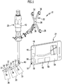
- FIG. 1 shows a perspective view of an occupied with the reference numeral 10 advantageous embodiment of a medical instrumentation.
- the instrumentation 10 comprises a medical-technical article 12.
- the article 12 is an implant 14, namely in the form of a stabilization element 16 of a surgical fixation system.
- the stabilizing element 16 is designed as a rod 18 having a longitudinal extent.
- the instrumentation 10 further includes an implantation tool 20 for the stabilization element 16.
- the instrumentation 10 comprises a medical marking device 22 and a medical navigation system 24.
- the instrumentation 10 comprises a in FIG. 2 Deformation device 26 shown in side view for deforming the stabilizing element 16 and a further medical marking device 28 arranged thereon.
- the fixation system serves to fix in FIG. 1 schematically illustrated vertebral bodies 30 against movement relative to each other.
- the fixation system anchoring elements 32 in the form of bone screws 34 which are fixed to the vertebral bodies 30.
- the stabilizing element 16 is fixed to the bone screws 34.
- the rod-shaped stabilizing element 16 the bone screws 34 are rigidly connected to each other.
- the rod 18 has a desired, defined shape.
- the marking device 22 is designed here as a so-called rigid body.
- the marking device 22 comprises a plurality of marking elements 36.
- the marking elements 36 are held on a common holder 38.
- the marking elements 36 are designed to be retroreflective, in particular for visible light.
- the marking device 22 is held indirectly on the rod 18 in the instrumentation 10 in a defined spatial arrangement.
- the implantation tool 20 serves for this purpose.
- the rod 18 is held, for example, at a distal end 40 of the implantation tool 20 and occupies a defined spatial arrangement relative thereto.
- the marking device 22 is likewise held in a defined spatial arrangement on the implantation tool 20, for example on or near a grip element 42 of the implantation tool 20.
- the spatial position and orientation of the rod 18 relative to the position and orientation of the marker 22 is known. If the marking device 22 is tracked by means of the navigation system 24, it is also possible to deduce the position and orientation of the rod 18.
- the marking device 22 defines a reference coordinate system.
- the navigation system 24 is configured here as a handheld, integrated navigation system.
- this is a smartphone 44 or tablet computer.
- “Integrated” is present in particular to be understood in such a way that the components of the navigation system 24 are arranged in a common housing 46 of the navigation system 24.
- the navigation system 24 has a data processing unit 48 arranged in the housing 46.
- an optical detection unit 52 having a camera 50 is arranged in the housing 46. Conveniently, exactly one digital camera 50 is provided.
- a reference unit is also arranged in the housing 46, configured as a display unit 54.
- the display unit 54 is in particular a touchscreen.
- the navigation system 24 comprises a lighting unit 56 arranged in the housing 46, which comprises in particular an LED light source.
- a lighting unit 56 arranged in the housing 46, which comprises in particular an LED light source.
- visible light can be emitted in the direction of the marking device 22 with the illumination unit 56, and light reflected by its marking elements 36 can be received by the camera 50.
- the data processing unit 48 comprises, for example, a microprocessor or is designed as such, on which an application program of the navigation system 24 can be executed.
- the application program includes in particular algorithms for image processing.
- the instrumentation 10 may further comprise a memory unit 58, which is preferably arranged in the housing 46 of the navigation system 24.
- Information about the article 12 can be stored in the storage unit 58, for example its type and in particular its dimensions such as length, width, curvature or diameter.
- instrumentation 10 can be determined with the navigation system 24, the shape of the rod 18 in a simple manner.
- the operator with the camera 50 as in FIG. 1 (Without operator) shown schematically, record the marker 22 and the rod 18 create.
- the data processing unit 48 is programmed to determine the position and in particular the shape of the rod 18 on the basis of a photograph produced by the camera 50. This is in particular possible because due to the known spatial arrangement of the marking device 22 to the rod 18 by location and orientation of the marking device 22 relative to the camera 50, as explained above, also on the position and orientation of the rod 18 can be closed.
- the algorithms for image processing stored in the navigation system 24 analyze the image of the camera 50.
- information about the article 12 stored in the storage unit 58 may be used to analyze the image. This gives, for example, the opportunity to identify the article 12 as a bar 18 and thereby determine its shape in a simpler manner.
- the operator can be provided with indications on the display unit 54 that and how, in particular in which orientation, the at least one image is to be created. It is favorable if, in the case of an article 12 having a longitudinal extension, such as the rod 18, an optical axis of the camera 50 is aligned approximately transversely to the longitudinal extent of the article 12.
- the operator creates by means of the camera 50 two or more images of the marking device 22 and the rod 18 in preferably different orientation. This allows the data processing unit 48 to determine the shape and position of the rod 18 even more reliably. With more than two shots, it is advantageous if the shots and the respective orientation of the navigation system 24 relative to the marking device 22 and the rod 18 are different from each other in pairs.
- FIG. 1 shown schematically.
- the instrumentation 10 makes it possible to determine the shape and position of the rod 18 preoperatively, ex-situ or advantageously also in-situ.
- the data processing unit 48 can determine whether the rod 18 has the required shape, and in particular curvature, to allow the bone screws 34 to be connected together as intended. If this is the case, the rod 18 can be implanted with the implantation tool 20.
- the marking device 22 is fixed on the implantation tool 20.
- the rod 18 can be tracked during implantation. Since the shape and position of the rod 18 in the reference coordinate system are known, the user can be guided on the display unit 54 with instructions for guiding the implantation tool 20. It is assumed that the position of the bone screws 34 in the reference coordinate system defined by the marking device 22 is known. For example, one of the bone screws 34 is provided with a marker not shown in the drawing and the position of the other bone screws 34 known relative to this marker. As a result, the rod 18 can be tracked during insertion relative to the bone screws 34.
- FIG. 2 shows a deforming means 26 to change the shape of the rod 18.
- the deformation device 26 is configured as a bending device 62, in particular as a hand-held and manually operated bending pliers.
- the bending device 62 has, for example, branches 64 which can be pivoted relative to one another. At a distal end 66 of the branches 64 may be investment elements 68 can be arranged for application to the rod 18. By manual operation, the rod 18 can be bent.
- a further marking device 28 is preferably arranged.
- the marking device 28 can be tracked by the navigation system 24 in the same way as the marking device 22 and corresponds in its function to it.
- the rod 18 can be converted by bending with the bending device 62 in the desired shape.
- the data processing unit 48 it is possible, for example, for the data processing unit 48 to provide to the display unit 54 instructions for the operator as to how the bending device 62 is to be actuated.
- the bending of the rod 18 can be done in particular in situ. It is advantageous if the bending device 62 is tracked by the navigation system 24 via the marking device 28. This gives the possibility to guide the operator in particular in-situ for bending the rod 18. Starting points of the abutment elements 68 on the rod 18, the bending plane and the bending radius can be checked and verified by following the bending device 62 relative to the rod 18. If necessary, instructions for the operator to reposition the bender 62 on the rod 18 may be provided to the display unit 54.
- a mechanical deformation device can also be used.
- FIG. 3 shows in one of the FIG. 1 Similarly, a reference numeral 70 occupied second advantageous embodiment of an instrument according to the invention.
- the achievable with the instrumentation 10 advantages can also be achieved with the instrument 70. To avoid repetition, reference may be made to the above statements.
- the deformation device 26 may be part of the instrumentation 70.
- the rod 18 is designed to be longer in relation to the embodiment of the instrumentation 10.
- the instrumentation 70 has a further marking device 72 which, like the marking device 22, can be tracked by the navigation system 24 and corresponds to it in its function.
- the marking device 72 can be releasably fixed to the rod 18 at different positions, for example by jamming.
- the FIG. 3 schematically shows a determination of the marking device 72 in the region of a distal end portion of the rod 18th
- the marking device 72 is positioned in this way in a defined spatial arrangement to the rod 18.
- a portion of the rod 18 is detected with the marker 72.
- the position and the shape of this section of the rod 18 can be determined from the data processing unit 48 on the basis of a respective image.
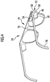
- FIG. 4 shows a different compared to the smartphone 44 embodiment of a navigation system 24, namely in the form of a data glasses 74th Die Data goggles 74 may be used instead of or in addition to the smartphone 44 in an instrumentation according to the invention, ie in particular the instruments 10 and / or 70.
- the data glasses 74 can be worn by an operator, not shown in the drawing in the manner of a conventional glasses, lying on the ears and on the nose. It may be provided that spectacle lenses are used on the spectacle frame 76, but this is not absolutely necessary.
- the data capture unit 52, the data processing unit 48, the storage unit 58 and the display unit 54 are held on the data glasses. As with the smartphone 44, the operator can be shown image contents on the image display of the display unit 54.
- the lighting unit 56 is held on the eyeglass frame 76.
- a battery 78 may be further held on the eyeglass frame 76.
Landscapes
- Health & Medical Sciences (AREA)
- Orthopedic Medicine & Surgery (AREA)
- Life Sciences & Earth Sciences (AREA)
- Surgery (AREA)
- Engineering & Computer Science (AREA)
- Neurology (AREA)
- Biomedical Technology (AREA)
- General Health & Medical Sciences (AREA)
- Veterinary Medicine (AREA)
- Heart & Thoracic Surgery (AREA)
- Public Health (AREA)
- Animal Behavior & Ethology (AREA)
- Nuclear Medicine, Radiotherapy & Molecular Imaging (AREA)
- Medical Informatics (AREA)
- Molecular Biology (AREA)
- Robotics (AREA)
- Vascular Medicine (AREA)
- Transplantation (AREA)
- Oral & Maxillofacial Surgery (AREA)
- Cardiology (AREA)
- Surgical Instruments (AREA)
- Prostheses (AREA)
Abstract
Description
- Die Erfindung betrifft ein medizinisches Instrumentarium.
- Außerdem betrifft die Erfindung ein Verfahren zum Ermitteln der Form eines medizintechnischen Artikels.
- Der medizintechnische Artikel kann hinsichtlich Form und Funktion auf unterschiedlichste Weise ausgestaltet sein. Beispielsweise ist der medizintechnische Artikel ein Implantat. Ein Beispiel für einen Artikel in Gestalt eines Implantates ist ein Stabilisierungselement eines medizinischen Fixationssystems. Bei einer andersartigen Ausführungsform kann der medizintechnische Artikel ein chirurgisches Instrument sein.
- Die Erfindung wird vorliegend insbesondere am Beispiel eines Implantates und speziell eines Stabilisierungselementes beschrieben, ist jedoch nicht hierauf beschränkt.
- Stabilisierungselemente kommen insbesondere als Bestandteile von chirurgischen Fixationssystemen zum Einsatz. Mittels eines derartigen Fixationssystemes lassen sich beispielsweise Knochen oder Knochenstücke relativ zueinander fixieren; ein typisches Anwendungsgebiet ist die Wirbelsäulenchirurgie, bei der Wirbelkörper gegen Bewegung relativ zueinander gesichert werden sollen. Dabei werden in den Wirbelkörpern Verankerungselemente, beispielsweise Knochenschrauben, verankert und mittels des Stabilisierungselementes, beispielsweise eines Stabes, miteinander verbunden. Ein derartiges Fixationssystem ist beispielsweise in der
DE 10 2010 016 448 A1 beschrieben. - Um einen Eingriff möglichst geringer Invasivität vorzunehmen ist es wünschenswert festzustellen, ob das Stabilisierungselement dazu geeignet ist, die Verankerungselemente so miteinander zu verbinden, dass die gewünschte Fixation erzielt wird. Erforderlichenfalls kann die Form des Stabilisierungselementes geändert oder ein Stabilisierungselement aus einer Mehrzahl von zur Verfügung stehenden Stabilisierungselementen unterschiedlicher Form ausgewählt werden. Vorzugsweise erfolgt die Feststellung, die Formänderung und/oder die Auswahl vor der Implantation des Stabilisierungselementes.
- In der nicht-vorveröffentlichten Patentanmeldung
DE 10 2015 102 776 ist beschrieben, wie die Form eines Stabilisierungselementes anhand von Aufnahmen ermittelbar ist, die mittels eines Navigationssystems erstellt und von einer Datenverarbeitungseinheit verarbeitet werden. In derDE 103 14 882 A1 , derUS 2005/0262911 A1 und derUS 8,549,888 B2 sind jeweils Vorrichtungen beschrieben, mit denen die Form chirurgischer Stabilisierungselemente verändert werden kann. - Aufgabe der vorliegenden Erfindung ist es, ein Instrumentarium und ein Verfahren bereitzustellen, mit dem die Form eines medizintechnischen Artikels auf einfache Weise ermittelt werden kann.
- Diese Aufgabe wird erfindungsgemäß gelöst durch ein medizinisches Instrumentarium mit einem Navigationssystem, das eine eine Kamera aufweisende optische Erfassungseinheit aufweist und eine mit dieser gekoppelte Datenverarbeitungseinheit, mit einem medizintechnischen Artikel sowie einer Markiereinrichtung, welche direkt oder indirekt am Artikel gehalten und in definierter räumlicher Anordnung zu diesem positioniert ist, oder welche Markiereinrichtung vom Artikel umfasst oder gebildet ist, wobei mit dem Navigationssystem die Lage und Orientierung der Markiereinrichtung ermittelbar ist, wobei mittels der Erfassungseinheit mindestens eine Aufnahme der Markiereinrichtung und des Artikels erstellbar ist und die Position und Form des Artikels von der Datenverarbeitungseinheit anhand einer Aufnahme ermittelbar ist.
- In die vorliegende Erfindung fließt der Gedanke mit ein, dass mittels eines medizinischen Navigationssystems eine Markiereinrichtung hinsichtlich Lage und Orientierung und dementsprechend Lageänderung und Orientierungsänderung erfasst werden kann. Die Lage und Orientierung kann dabei relativ zur Erfassungseinheit festgestellt werden, wobei die Markiereinrichtung ihrerseits ein Referenzkoordinatensystem definiert. Das Navigationssystem weist eine optische Erfassungseinheit mit mindestens einer Kamera auf, mit der Aufnahmen des medizintechnischen Artikels, jedenfalls zumindest eines Abschnittes davon, einschließlich der daran angeordneten Markiereinrichtung erstellt werden können. Die Position und die Form des Artikels kann aus insbesondere genau einer Aufnahme von der Datenverarbeitungseinheit ermittelt werden. Hierzu können in der Datenverarbeitungseinheit Bildverarbeitungsalgorithmen ausführbar hinterlegt sein, die die eine Aufnahme der mindestens einen Kamera analysieren und anhand der Lage- und/oder Orientierungsinformation aufgrund der Markiereinrichtung die dreidimensionale Gestalt des Artikels in hinreichender Genauigkeit bestimmen. Die Bestimmung der Position des Artikels kann im Referenzkoordinatensystem aufgrund der definierten räumlichen Beziehung der Markiereinrichtung zum Artikel festgestellt werden.
- Das erfindungsgemäße Instrumentarium erlaubt es insbesondere, die Form des Artikels zu ermitteln, ohne dass dieser zu diesem Zweck räumlich fixiert sein muss. Der apparative Aufwand, um die Form des Artikels zu ermitteln, kann dadurch gering gehalten werden. Dies erleichtert auch die Handhabung des Instrumentariums.
- Günstigerweise sind in einer Speichereinheit Informationen über den Artikel gespeichert, die von der Datenverarbeitungseinheit bei der Ermittlung der Form des Artikels herangezogen werden. In der Speichereinheit können beispielsweise Informationen über Abmessungen des Artikels hinterlegt sein, zum Beispiel dessen Länge, Breite oder Durchmesser. Durch Vergleich von Abmessungen, die in Bezug auf unterschiedliche Artikel in der Speichereinheit hinterlegt sind, mit anhand von der einen Aufnahme ermittelten abgeschätzten Abmessungen gibt dies auch die Möglichkeit, den Artikel zu identifizieren und die Form anhand der in der Speichereinheit hinterlegten Informationen zu rekonstruieren.
- Es kann vorgesehen sein, dass eine Mehrzahl von Aufnahmen der Markiereinrichtung und des Artikels oder zumindest eines Abschnittes davon erstellbar ist, die vorzugsweise unter unterschiedlicher Orientierung erstellt werden. Dies gibt die Möglichkeit, die Form des Artikels noch zuverlässiger zu bestimmen.
- Günstig ist es, wenn aufeinanderfolgend mehr als zwei Aufnahmen des Artikels und der Markiereinrichtung erstellbar sind, anhand derer die Form des Artikels ermittelbar ist, wobei die Orientierungen und Aufnahmen paarweise voneinander unterschiedlich sind. Dadurch lässt sich die Form des Artikels noch genauer ermitteln.
- Weist der Artikel eine Längserstreckung auf, beispielsweise bei stabförmiger Ausgestaltung, werden die Aufnahmen bevorzugt unter Ausrichtung einer optischen Achse der mindestens einen Kamera im Winkel und insbesondere quer zur Längsrichtung des Artikels aufgenommen. Zwischen zwei Aufnahmen wird die Kamera bevorzugt um 90° bezüglich der Längserstreckung des Artikels gedreht.
- Vorteilhafterweise umfasst die Erfassungseinheit genau eine Kamera, um die konstruktive Ausgestaltung des Navigationssystems zu vereinfachen. Das Vorsehen einer Stereokamera ist nicht erforderlich.
- Für eine konstruktiv einfache Ausgestaltung und eine kostengünstige Fertigung des Instrumentariums ist es günstig, wenn das Navigationssystem ein handhaltbares integriertes Navigationssystem ist. Unter "integriert" wird vorliegend insbesondere verstanden, dass die Erfassungseinheit und die Datenverarbeitungseinheit in einem gemeinsamen Gehäuse angeordnet sind. In dem Gehäuse ist vorzugsweise eine Anzeigeeinheit des Navigationssystems angeordnet.
- Beispielsweise ist das handhaltbare integrierte Navigationssystem ein Smartphone oder ein Tablet-Computer. Auf dem Smartphone oder Tabletcomputer kann ein Datenverarbeitungsprogramm ausführbar gespeichert sein, mit dem Daten der Erfassungseinheit von der Datenverarbeitungseinheit analysiert und die Form des Artikels ermittelt werden können.
- Bei einer vorteilhaften Ausführungsform kann das Navigationssystem eine Datenbrille sein oder umfassen. Die Datenbrille kann nach Art einer Brille oder eines Brillengestells getragen werden. Nicht erforderlich ist, dass Brillengläser, geschliffen oder ungeschliffen (Glas oder Kunststoff) vorhanden sind. Ausreichend ist beispielsweise ein Gestell zum An- oder Aufliegen an den Ohren und der Nase, an dem die optische Erfassungseinheit mit der Kamera, eine Anzeigeeinheit und vorzugsweise die Datenverarbeitungseinheit gehalten sind. Die Speichereinheit und/oder eine Beleuchtungseinheit kann ebenfalls an dem Gestell gehalten sein. An der Datenbrille kann eine Batterie zur Energieversorgung vorgesehen sein.
- Von Vorteil ist es, wenn das Navigationssystem eine mit der Datenverarbeitungseinheit gekoppelte Anzeigeeinheit umfasst, an der die Aufnahmen des Artikels darstellbar oder bereitstellbar sind und/oder Hinweise für einen Benutzer, die Aufnahmen durchzuführen und/oder eine Darstellung des Artikels, ermittelt anhand der Aufnahmen.
- Das Navigationssystem kann eine Beleuchtungseinheit aufweisen, mit der Licht, insbesondere sichtbares Licht, in Richtung auf die Markiereinrichtung emittierbar ist. Die Beleuchtungseinheit umfasst zum Beispiel mindestens eine LED-Lichtquelle und wird vorzugsweise von dem integrierten, handhaltbaren Navigationssystem umfasst.
- Der medizintechnische Artikel kann ein chirurgisches Instrument sein, oder der medizintechnische Artikel kann ein Implantat sein.
- Bei dem Implantat kann es sich um ein im Körper verbleibendes Implantat handeln oder um ein nur vorübergehend verwendetes Probeimplantat, das auch als Werkzeug des Instrumentariums angesehen werden kann.
- Das Instrumentarium kann ein Implantationswerkzeug für das Implantat aufweisen, an dem dieses und die Markiereinrichtung gehalten sind. Das Implantationswerkzeug ist beispielsweise handgeführt und erlaubt es, das Implantat bevorzugt perkutan und minimalinvasiv zu implantieren. Über das Implantationswerkzeug ist die Markiereinrichtung in definierter räumlicher Anordnung zum Implantat angeordnet. Die Markiereinrichtung kann mit dem Implantationswerkzeug lösbar verbindbar sein. Vorliegende Ausführungsform erlaubt es, die Form des als Implantat ausgestalteten Artikels zu ermitteln. Zugleich ist die Möglichkeit gegeben, das Implantat über das Implantationswerkzeug mit der daran gehaltenen Markiereinrichtung bei der Implantation zu verfolgen. Besonders bei perkutaner Implantation wird dadurch die Handhabung des Artikels erheblich vereinfacht.
- Das Implantat ist bei einer vorteilhaften Ausführungsform des Instrumentariums ein Stabilisierungselement eines chirurgischen Fixationssystems. Auf derartige Fixationssysteme und Stabilisierungselemente wurde bereits eingangs eingegangen.
- Das Stabilisierungselement kann insbesondere ein Stab sein.
- Vorzugsweise weist das Instrumentarium eine Verformungseinrichtung auf, mit der die Form des Stabilisierungselementes veränderbar ist.
- Die Verformungseinrichtung ist zum Beispiel eine Biegeeinrichtung zum Biegen eines Stabes, als der das Stabilisierungselement ausgestaltet ist.
- Günstig ist es, wenn einer Bedienperson von der Datenverarbeitungseinheit an einer Hinweiseinheit des Navigationssystems, beispielsweise an einer Anzeigeeinheit, Formänderungsinformationen zur Handhabung der Verformungseinrichtung bereitstellbar sind, um das Stabilisierungselement ausgehend von der ermittelten Form in eine vorgebbare Form zu bringen. Beispielsweise kann die Datenverarbeitungseinheit vergleichen, ob die ermittelte Form des Stabilisierungselementes mit einer erforderlichen, gewünschten Form übereinstimmt.
- Die erforderliche Form kann zum Beispiel ermittelt werden, indem die Relativpositionen von Verankerungselementen des Fixationssystems festgestellt werden mit der Maßgabe, dass die Verankerungselemente mit dem Stabilisierungselement zu verbinden sind. Weicht die anhand der Aufnahmen ermittelte Form von der erforderlichen Form ab, kann das Stabilisierungselement mit der Verformungseinrichtung verformt werden. Zu diesem Zweck können der Bedienperson an der Anzeigeeinheit Formänderungsinformationen bereitgestellt werden und dadurch die Handhabung des Instrumentariums erheblich vereinfacht werden.
- In entsprechender Weise ist es günstig, wenn vom Navigationssystem über eine Kommunikationsschnittstelle Formänderungsinformationen an die Verformungseinrichtung übertragbar sind, um das Stabilisierungselement ausgehend von der ermittelten Form in eine vorgebbare Form zu bringen. Die Verformungseinrichtung kann das Stabilisierungselement vorzugsweise ohne Zutun der Bedienperson anhand der ihr zugeführten Formänderungsinformationen in die vorgebbare, erforderliche Form bringen.
- Insbesondere ist denkbar, dass die Form des Stabilisierungselementes in-situ erfasst und/oder bevorzugt in-situ mittels der Verformungseinrichtung verändert wird. Alternativ kann vorgesehen sein, dass die Form vom Stabilisierungselement ex-situ erfasst und/oder ex-situ mittels der Verformungseinrichtung verändert wird.
- Wie erwähnt, kann der Artikel ein chirurgisches Instrument sein.
- Bei einer vorteilhaften Ausführungsform des Instrumentariums kann das chirurgische Instrument ein Schraubinstrument oder ein Einschlaginstrument sein. Unter Einsatz der Markiereinrichtung kann es sich bei dem Instrument dementsprechend um ein navigiertes Schraubinstrument oder ein navigiertes Einschlaginstrument handeln. Mittels des Instrumentariums ist die Möglichkeit gegeben, etwaige Verformungen des Schraubinstrumentes (beispielsweise eine Unrundheit) oder des Einschlaginstrumentes festzustellen. Die Form des Instrumentes, ermittelt anhand der einen Aufnahme, kann mit einer beispielsweise aus einer Speichereinheit gelesenen Form des Instrumentes verglichen und dadurch eine Verformung ermittelt werden. Beim Einsatz des Instrumentes können derartige Verformungen kompensiert werden. Der Benutzer kann über die Verformung des Instrumentes beispielsweise an einer Anzeigeeinheit des Instrumentariums informiert werden und die Handhabung des Instrumentes entsprechend anpassen.
- Es kann vorgesehen sein, dass der Artikel Markierelemente der Markiereinrichtung umfasst oder bildet, beispielsweise sind die Markierelemente ausgestaltet als bevorzugt reflektierende Punkte oder Linien am Artikel.
- Die Markiereinrichtung kann am Artikel mittelbar oder unmittelbar lösbar festgelegt oder festlegbar sein.
- Bei einer vorteilhaften Ausführungsform des Instrumentariums ist die Markiereinrichtung einstückig mit dem Artikel verbunden, beispielsweise an diesen angeformt oder angeschweißt.
- Günstigerweise ist eine Sollbruchstelle vorgesehen zum Trennen der Markiereinrichtung vom Artikel. Nach Ermitteln der Form des Artikels kann die Markiereinrichtung von diesem getrennt werden. Ein als Implantat und speziell Stabilisierungselement ausgestalteter Artikel kann beispielsweise anschließend implantiert werden.
- Es kann vorgesehen sein, dass eine Mehrzahl von Markiereinrichtungen direkt oder indirekt am Artikel gehalten und in definierter räumlicher Anordnung zu diesem positioniert oder von diesem umfasst oder gebildet ist, wobei anhand von mehreren Aufnahmen, die jeweils eine Markiereinrichtung und einen Abschnitt des Artikels erfassen, die Position und Form des Abschnitts des Artikels von der Datenverarbeitungseinheit ermittelbar ist. Beispielsweise ist eine Mehrzahl derartiger Markiereinrichtungen am Artikel gehalten oder von diesem gebildet. Eine jeweilige Markiereinrichtung kann mit einem jeweiligen Abschnitt des Artikels erfasst und daraus die Position und die Form des Abschnittes des Artikels anhand der einen Aufnahme ermittelt werden. Dies kann vorzugsweise in-situ durchgeführt werden, jedoch ist auch eine ex-situ Erfassung und Ermittlung der Form der jeweiligen Abschnitte möglich.
- Wie bereits erwähnt, betrifft die vorliegende Erfindung auch ein Verfahren. Die eingangs gestellte Aufgabe wird durch ein erfindungsgemäßes Verfahren zum Ermitteln der Form eines medizintechnischen Artikels unter Einsatz eines Instrumentariums der vorstehend genannten Art gelöst, wobei mittels der Erfassungseinheit mindestens eine Aufnahme der Markiereinrichtung und des Artikels erstellt wird und die Position und Form des Artikels von der Datenverarbeitungseinheit anhand einer Aufnahme ermittelt wird.
- Die Vorteile, die bereits im Zusammenhang mit der Erläuterung des erfindungsgemäßen Instrumentariums erwähnt wurden, können unter Ausübung des Verfahrens ebenfalls erzielt werden. Diesbezüglich kann auf die voranstehenden Ausführungen verwiesen werden.
- Vorteilhafte Ausführungsbeispiele des erfindungsgemäßen Verfahrens ergeben sich durch vorteilhafte Ausführungsformen des erfindungsgemäßen Instrumentariums.
- Die nachfolgende Beschreibung bevorzugter Ausführungsformen der Erfindung dient im Zusammenhang mit der Zeichnung der näheren Erläuterung der Erfindung. Es werden vorteilhafte Ausführungsformen eines erfindungsgemäßen Instrumentariums beschrieben, mit denen das erfindungsgemäße Verfahren durchführbar ist. Es zeigen:
- Figur 1:
- eine schematische perspektivische Teildarstellung eines erfindungsgemäßen Instrumentariums;
- Figur 2:
- eine Verformungseinrichtung des Instrumentariums aus
Figur 1 ; - Figur 3:
- eine schematische perspektivische Teildarstellung (mit Ausnahme einer Verformungseinrichtung) einer weiteren Ausführungsform des erfindungsgemäßen Instrumentariums; und
- Figur 4:
- eine schematische perspektivische Darstellung eines Navigationssystems eines erfindungsgemäßen Instrumentariums.
-
Figur 1 zeigt in perspektivischer Darstellung eine mit dem Bezugszeichen 10 belegte vorteilhafte Ausführungsform eines medizinischen Instrumentariums. Das Instrumentarium 10 umfasst einen medizintechnischen Artikel 12. Vorliegend handelt es sich bei dem Artikel 12 um ein Implantat 14, nämlich in Gestalt eines Stabilisierungselementes 16 eines chirurgischen Fixationssystems. Das Stabilisierungselement 16 ist als eine Längserstreckung aufweisender Stab 18 ausgestaltet. - Das Instrumentarium 10 umfasst ferner ein Implantationswerkzeug 20 für das Stabilisierungselement 16. Außerdem umfasst das Instrumentarium 10 eine medizinische Markiereinrichtung 22 und ein medizintechnisches Navigationssystem 24.
- Ferner umfasst das Instrumentarium 10 eine in
Figur 2 in Seitenansicht dargestellte Verformungseinrichtung 26 zum Verformen des Stabilisierungselementes 16 und eine daran angeordnete weitere medizinische Markiereinrichtung 28. - Das Fixationssystem dient zur Fixierung von in
Figur 1 schematisch dargestellten Wirbelkörpern 30 gegen Bewegung relativ zueinander. Zu diesem Zweck weist das Fixationssystem Verankerungselemente 32 auf in Gestalt von Knochenschrauben 34, die an den Wirbelkörpern 30 fixiert sind. In Anwendung des Fixationssystems wird das Stabilisierungselement 16 an den Knochenschrauben 34 fixiert. Über das stabförmige Stabilisierungselement 16 sind die Knochenschrauben 34 starr miteinander verbindbar. - Um die erforderliche Relativposition der Knochenschrauben 34 und damit der Wirbelkörper 30 sicherzustellen, ist es in der Praxis von Bedeutung, dass der Stab 18 eine gewünschte, definierte Form aufweist. Außerdem ist es von Bedeutung, dass die Position des Stabes 18 im Hinblick auf die Führung des Implantationswerkzeuges 20 bekannt ist. Die Position und die Form des Stabes 18 werden anhand des Navigationssystems 24 wie nachfolgend erläutert ermittelt.
- Die Markiereinrichtung 22 ist vorliegend als sogenannter Rigid Body ausgestaltet. Die Markiereinrichtung 22 umfasst eine Mehrzahl von Markierelementen 36. Die Markierelemente 36 sind an einer gemeinsamen Halterung 38 gehalten. Vorzugsweise sind die Markierelemente 36 retroreflektierend für insbesondere sichtbares Licht ausgebildet.
- Die Markiereinrichtung 22 ist beim Instrumentarium 10 in definierter räumlicher Anordnung mittelbar am Stab 18 gehalten. Zu diesem Zweck dient das Implantationswerkzeug 20. Der Stab 18 ist beispielsweise an einem distalen Ende 40 des Implantationswerkzeugs 20 gehalten und nimmt relativ zu diesem eine definierte räumliche Anordnung ein. Die Markiereinrichtung 22 ist ebenfalls in definierter räumlicher Anordnung am Implantationswerkzeug 20 gehalten, beispielsweise an oder nahe einem Griffelement 42 des Implantationswerkzeugs 20.
- Aus diesem Grund ist die räumliche Lage und Orientierung des Stabes 18 relativ zur Lage und Orientierung der Markiereinrichtung 22 bekannt. Wird die Markiereinrichtung 22 mittels des Navigationssystems 24 verfolgt, kann dadurch auch auf die Lage und die Orientierung des Stabes 18 geschlossen werden. Die Markiereinrichtung 22 definiert ein Referenzkoordinatensystem.
- Zur erleichterten Handhabung und zur einfachen Ausgestaltung des Instrumentariums 10 ist das Navigationssystem 24 vorliegend als handhaltbares, integriertes Navigationssystem ausgestaltet. Beispielsweise handelt es sich dabei um ein(en) Smartphone 44 oder Tablet-Computer. "Integriert" ist vorliegend insbesondere dahingehend aufzufassen, dass die Komponenten des Navigationssystems 24 in einem gemeinsamen Gehäuse 46 des Navigationssystems 24 angeordnet sind. Beispielsweise weist das Navigationssystem 24 eine im Gehäuse 46 angeordnete Datenverarbeitungseinheit 48 auf.
- Ferner ist eine eine Kamera 50 aufweisende optische Erfassungseinheit 52 im Gehäuse 46 angeordnet. Günstigerweise ist genau eine digitale Kamera 50 vorgesehen. Im Gehäuse 46 ist außerdem eine Hinweiseinheit angeordnet, ausgestaltet als Anzeigeeinheit 54. Die Anzeigeeinheit 54 ist insbesondere ein Touchscreen.
- Ferner umfasst das Navigationssystem 24 eine im Gehäuse 46 angeordnete Beleuchtungseinheit 56, die insbesondere eine LED-Lichtquelle umfasst. Mit der Beleuchtungseinheit 56 kann insbesondere sichtbares Licht in Richtung der Markiereinrichtung 22 emittiert werden, und von deren Markierelementen 36 reflektiertes Licht kann von der Kamera 50 empfangen werden.
- Die Datenverarbeitungseinheit 48 umfasst zum Beispiel einen Mikroprozessor oder ist als solcher ausgestaltet, auf dem ein Anwendungsprogramm des Navigationssystems 24 ausgeführt werden kann. Das Anwendungsprogramm umfasst insbesondere Algorithmen für die Bildverarbeitung.
- Das Instrumentarium 10 kann ferner eine Speichereinheit 58 umfassen, die vorzugsweise im Gehäuse 46 des Navigationssystems 24 angeordnet ist. In der Speichereinheit 58 können Informationen über den Artikel 12 gespeichert sein, beispielsweise dessen Typ und insbesondere dessen Abmessungen wie Länge, Breite, Krümmung oder Durchmesser.
- Beim Instrumentarium 10 kann mit dem Navigationssystem 24 die Form des Stabes 18 auf einfache Weise ermittelt werden. Zu diesem Zweck kann die Bedienperson mit der Kamera 50, wie in
Figur 1 (ohne Bedienperson) schematisch dargestellt, Aufnahmen der Markiereinrichtung 22 und des Stabes 18 erstellen. - Die Datenverarbeitungseinheit 48 ist so programmiert, dass sie anhand einer Aufnahme, die von der Kamera 50 erstellt wird, die Position und insbesondere die Form des Stabes 18 ermittelt. Dies ist insbesondere dadurch möglich, dass aufgrund der bekannten räumlichen Anordnung der Markiereinrichtung 22 zum Stab 18 durch Lage und Orientierung der Markiereinrichtung 22 relativ zur Kamera 50, wie vorstehend erläutert, auch auf die Lage und Orientierung des Stabes 18 geschlossen werden kann. Die Algorithmen für die Bildverarbeitung, die im Navigationssystem 24 hinterlegt sind, analysieren die Aufnahme der Kamera 50.
- Ergänzend können Informationen über den Artikel 12, die in der Speichereinheit 58 gespeichert sind, zur Analyse der Aufnahme herangezogen werden. Dies gibt beispielsweise die Möglichkeit, den Artikel 12 als Stab 18 zu identifizieren und dadurch dessen Form auf einfachere Weise festzustellen.
- Vorzugsweise können der Bedienperson an der Anzeigeeinheit 54 Hinweise bereitgestellt werden, dass und wie, insbesondere in welcher Orientierung, die mindestens eine Aufnahme zu erstellen ist. Dabei ist es günstig, wenn bei einem eine Längserstreckung aufweisenden Artikel 12, wie dem Stab 18, eine optische Achse der Kamera 50 ungefähr quer zur Längserstreckung des Artikels 12 ausgerichtet ist.
- Denkbar ist auch, dass die Bedienperson mittels der Kamera 50 zwei oder mehr Aufnahmen der Markiereinrichtung 22 und des Stabes 18 in vorzugsweise unterschiedlicher Orientierung erstellt. Dies erlaubt es der Datenverarbeitungseinheit 48, die Form und Position des Stabes 18 noch zuverlässiger zu ermitteln. Bei mehr als zwei Aufnahmen ist es von Vorteil, wenn die Aufnahmen und die jeweilige Orientierung des Navigationssystems 24 relativ zur Markiereinrichtung 22 und zum Stab 18 paarweise voneinander unterschiedlich sind.
- An der Anzeigeeinheit 54 können die Aufnahmen selbst oder eine Darstellung des Stabes 18, ermittelt anhand der einen oder mehreren Aufnahmen, dargestellt werden. Dies ist in
Figur 1 schematisch gezeigt. - Das Instrumentarium 10 erlaubt es insbesondere, die Form und Position des Stabes 18 präoperativ, ex-situ oder vorteilhafterweise auch in-situ zu ermitteln.
- Ist die Form des Stabes 18 ermittelt, kann die Datenverarbeitungseinheit 48 feststellen, ob der Stab 18 die erforderliche Form und insbesondere Krümmung aufweist, damit die Knochenschrauben 34 wie vorgesehen miteinander verbunden werden können. Ist dies der Fall, kann der Stab 18 mit dem Implantationswerkzeug 20 implantiert werden.
- Als besonders vorteilhaft erweist es sich dabei, dass die Markiereinrichtung 22 am Implantationswerkzeug 20 festgelegt ist. Unter Verfolgung der Markiereinrichtung 22 mit dem Navigationssystem 24 kann der Stab 18 bei der Implantation getrackt werden. Da die Form und die Position des Stabes 18 im Referenzkoordinatensystem bekannt sind, kann der Benutzer an der Anzeigeeinheit 54 mit Hinweisen zum Führen des Implantationswerkzeuges 20 angeleitet werden. Dabei wird davon ausgegangen, dass die Lage der Knochenschrauben 34 in dem durch die Markiereinrichtung 22 definierten Referenzkoordinatensystem bekannt ist. Beispielsweise ist eine der Knochenschrauben 34 mit einer in der Zeichnung nicht dargestellten Markiereinrichtung versehen und die Position der anderen Knochenschrauben 34 relativ zu dieser Markiereinrichtung bekannt. Dadurch kann der Stab 18 beim Einsetzen relativ zu den Knochenschrauben 34 getrackt werden.
-
Figur 2 zeigt eine Verformungseinrichtung 26, um die Form des Stabes 18 zu verändern. Die Verformungseinrichtung 26 ist ausgestaltet als Biegeeinrichtung 62, insbesondere als handhaltbare und handbetätigbare Biegezange. Die Biegeeinrichtung 62 weist beispielsweise relativ zueinander verschwenkbare Branchen 64 auf. An einem distalen Ende 66 der Branchen 64 können Anlageelemente 68 angeordnet sein zum Anlegen am Stab 18. Durch Handbetätigung kann der Stab 18 gebogen werden. - An der Biegeeinrichtung 62 ist vorzugsweise eine weitere Markiereinrichtung 28 angeordnet. Die Markiereinrichtung 28 kann entsprechend wie die Markiereinrichtung 22 vom Navigationssystem 24 verfolgt werden und stimmt in seiner Funktion mit dieser überein.
- Wenn die Form des Stabes 18, die anhand der einen Aufnahme ermittelt worden ist, nicht mit der erforderlichen Form übereinstimmt, kann der Stab 18 durch Biegen mit der Biegeeinrichtung 62 in die gewünschte Form überführt werden. Zu diesem Zweck ist es zum Beispiel möglich, dass die Datenverarbeitungseinheit 48 an der Anzeigeeinheit 54 Hinweise für die Bedienperson bereitstellt, wie die Biegeeinrichtung 62 zu betätigen ist.
- Das Biegen des Stabes 18 kann insbesondere in-situ erfolgen. Von Vorteil ist es, wenn die Biegeeinrichtung 62 dabei über die Markiereinrichtung 28 vom Navigationssystem 24 verfolgt wird. Dies gibt die Möglichkeit, die Bedienperson insbesondere in-situ zum Biegen des Stabes 18 anzuleiten. Ansatzpunkte der Anlageelemente 68 am Stab 18, die Biegeebene und der Biegeradius können durch Verfolgen der Biegeeinrichtung 62 relativ zum Stab 18 überprüft und verifiziert werden. Erforderlichenfalls können an der Anzeigeeinheit 54 Hinweise für die Bedienperson bereitgestellt werden, die Biegeeinrichtung 62 am Stab 18 zu repositionieren.
- Anstelle der handbetätigten Verformungseinrichtung 26 kann, wie bereits erwähnt, auch eine maschinelle Verformungseinrichtung zum Einsatz kommen.
- Die
Figur 3 zeigt in einer derFigur 1 ähnlichen Weise eine mit dem Bezugszeichen 70 belegte zweite vorteilhafte Ausführungsform eines erfindungsgemäßen Instrumentariums. Die mit dem Instrumentarium 10 erzielbaren Vorteile können mit dem Instrumentarium 70 ebenfalls erzielt werden. Zur Vermeidung von Wiederholungen kann auf voranstehende Ausführungen verwiesen werden. Die Verformungseinrichtung 26 kann Bestandteil des Instrumentariums 70 sein. - Für gleiche oder gleichwirkende Merkmale und Bauteile der Instrumentarien 70 und 10 werden identische Bezugszeichen benutzt.
- Beim Instrumentarium 70 ist der Stab 18 im Verhältnis zum Ausführungsbeispiel des Instrumentariums 10 länger ausgestaltet.
- Außerdem weist das Instrumentarium 70 eine weitere Markiereinrichtung 72 auf, die entsprechend wie die Markiereinrichtung 22 vom Navigationssystem 24 verfolgt werden kann und mit dieser in seiner Funktion übereinstimmt. Die Markiereinrichtung 72 kann am Stab 18 an unterschiedlichen Positionen lösbar festgelegt werden, beispielsweise durch Verklemmung. Die
Figur 3 zeigt schematisch eine Festlegung der Markiereinrichtung 72 im Bereich eines distalen Endabschnittes des Stabes 18. - Die Markiereinrichtung 72 ist auf diese Weise in definierter räumlicher Anordnung zum Stab 18 positioniert.
- Mit der Kamera 50 können mehrere Aufnahmen erstellt werden, die jeweils mindestens eine Markiereinrichtung 22, 72 und einen Abschnitt des Stabes 18 erfassen. Beispielsweise wird ein Abschnitt des Stabes 18 mit der Markiereinrichtung 72 erfasst. Die Position und die Form dieses Abschnittes des Stabes 18 kann anhand einer jeweiligen Aufnahme von der Datenverarbeitungseinheit 48 ermittelt werden.
- Dies gibt die Möglichkeit, die Form des Stabes 18 sukzessive durch mehrere Aufnahmen zu erfassen, wobei eine Referenzierung der Position des Stabes 18 insgesamt zusammen anhand der Markiereinrichtung 22 erfolgen kann.
-
Figur 4 zeigt eine im Vergleich zum Smartphone 44 andersartige Ausgestaltung eines Navigationssystems 24, nämlich in Gestalt einer Datenbrille 74. Die Datenbrille 74 kann statt oder ergänzend zu dem Smartphone 44 bei einem erfindungsgemäßen Instrumentarium zum Einsatz kommen, d. h. insbesondere den Instrumentarien 10 und/oder 70. - Die Datenbrille 74 kann von einer in der Zeichnung nicht dargestellten Bedienperson nach Art einer üblichen Brille getragen werden, aufliegend auf den Ohren und auf der Nase. Es kann vorgesehen sein, dass Brillengläser am Brillengestell 76 eingesetzt sind, dies ist jedoch nicht zwingend erforderlich.
- An der Datenbrille ist die die Kamera 50 aufweisende Erfassungseinheit 52 gehalten, die Datenverarbeitungseinheit 48, die Speichereinheit 58 sowie die Anzeigeeinheit 54. Entsprechend wie beim Smartphone 44 können der Bedienperson Bildinhalte an der Bildanzeige der Anzeigeeinheit 54 dargestellt werden.
- Auch die Beleuchtungseinheit 56 ist am Brillengestell 76 gehalten. Zur Energieversorgung kann am Brillengestell 76 ferner eine Batterie 78 gehalten sein.
-
- 10
- Instrumentarium
- 12
- Artikel
- 14
- Implantat
- 16
- Stabilisierungselement
- 18
- Stab
- 20
- Implantationswerkzeug
- 22
- Markiereinrichtung
- 24
- Navigationssystem
- 26
- Verformungseinrichtung
- 28
- Markiereinrichtung
- 30
- Wirbelkörper
- 32
- Verankerungselement
- 34
- Knochenschraube
- 36
- Markierelement
- 38
- Halterung
- 40
- distales Ende
- 42
- Griffelement
- 44
- Smartphone
- 46
- Gehäuse
- 48
- Datenverarbeitungseinheit
- 50
- Kamera
- 52
- Erfassungseinheit
- 54
- Anzeigeeinheit
- 56
- Beleuchtungseinheit
- 58
- Speichereinheit
- 62
- Biegeeinrichtung
- 64
- Branche
- 66
- distales Ende
- 68
- Anlageelement
- 70
- Instrumentarium
- 72
- Markiereinrichtung
- 74
- Datenbrille
- 76
- Brillengestell
- 78
- Batterie
Claims (15)
- Medizinisches Instrumentarium mit einem Navigationssystem (24), das eine eine Kamera (50) aufweisende optische Erfassungseinheit (52) aufweist und eine mit dieser gekoppelte Datenverarbeitungseinheit (48), mit einem medizintechnischen Artikel (12) sowie einer Markiereinrichtung (22), welche direkt oder indirekt am Artikel (12) gehalten und in definierter räumlicher Anordnung zu diesem positioniert ist, oder welche Markiereinrichtung vom Artikel (12) umfasst oder gebildet ist, wobei mit dem Navigationssystem (24) die Lage und Orientierung der Markiereinrichtung (22) ermittelbar ist, wobei mittels der Erfassungseinheit (52) mindestens eine Aufnahme der Markiereinrichtung (22) und des Artikels (12) erstellbar ist und die Position und Form des Artikels (12) von der Datenverarbeitungseinheit (48) anhand einer Aufnahme ermittelbar ist.
- Instrumentarium nach Anspruch 1, dadurch gekennzeichnet, dass in einer Speichereinheit (58) Informationen über den Artikel (12) gespeichert sind, die von der Datenverarbeitungseinheit (48) bei der Ermittlung der Form des Artikels (12) herangezogen werden.
- Instrumentarium nach Anspruch 1 oder 2, dadurch gekennzeichnet, dass das Navigationssystem (24) ein handhaltbares integriertes Navigationssystem ist.
- Instrumentarium nach einem der voranstehenden Ansprüche, dadurch gekennzeichnet, dass das Navigationssystem (24) ein Smartphone (44) oder ein Tablet-Computer ist, oder dass das Navigationssystem (24) eine Datenbrille (74) ist oder umfasst.
- Instrumentarium nach einem der voranstehenden Ansprüche, dadurch gekennzeichnet, dass das Navigationssystem (24) eine mit der Datenverarbeitungseinheit (48) gekoppelte Anzeigeeinheit (54) umfasst, an der die Aufnahmen des Artikels (12) darstellbar sind und/oder Hinweise für eine Bedienperson, die Aufnahmen durchzuführen und/oder eine Darstellung des Artikels (12), ermittelt anhand der Aufnahmen.
- Instrumentarium nach einem der voranstehenden Ansprüche, dadurch gekennzeichnet, dass der Artikel (12) ein chirurgisches Instrument oder dass der Artikel ein Implantat (14) ist, insbesondere dass das Instrumentarium ein Implantationswerkzeug (20) für das Implantat (14) aufweist, an dem dieses und die Markiereinrichtung (22) gehalten sind.
- Instrumentarium nach Anspruch 6, dadurch gekennzeichnet, dass das Implantat (14) ein Stabilisierungselement (16) eines chirurgischen Fixationssystems ist, vorzugsweise dass das Stabilisierungselement (16) ein Stab (18) ist.
- Instrumentarium nach Anspruch 7, dadurch gekennzeichnet, dass das Instrumentarium (10; 70) eine Verformungseinrichtung (26) aufweist, mit der die Form des Stabilisierungselementes (16) veränderbar ist.
- Instrumentarium nach Anspruch 8, dadurch gekennzeichnet, dass die Verformungseinrichtung (26) eine Biegeeinrichtung (62) zum Biegen eines Stabes (18) ist, als der das Stabilisierungselement (16) ausgestaltet ist.
- Instrumentarium nach Anspruch 6, dadurch gekennzeichnet, dass das chirurgische Instrument ein Schraubinstrument oder ein Einschlaginstrument ist.
- Instrumentarium nach einem der voranstehenden Ansprüche, dadurch gekennzeichnet, dass der Artikel (12) Markierelemente der Markiereinrichtung umfasst oder bildet, beispielsweise ausgestaltet als Punkte oder Linien am Artikel.
- Instrumentarium nach einem der voranstehenden Ansprüche, dadurch gekennzeichnet, dass die Markiereinrichtung (22) am Artikel (12) lösbar festgelegt oder festlegbar ist.
- Instrumentarium nach einem der voranstehenden Ansprüche, dadurch gekennzeichnet, dass die Markiereinrichtung einstückig mit dem Artikel verbunden ist, vorzugsweise dass eine Sollbruchstelle vorgesehen ist zum Trennen der Markiereinrichtung vom Artikel.
- Instrumentarium nach einem der voranstehenden Ansprüche, dadurch gekennzeichnet, dass eine Mehrzahl von Markiereinrichtungen (22, 72) direkt oder indirekt am Artikel (12) gehalten und in definierter räumlicher Anordnung zu diesem positioniert oder von diesem umfasst oder gebildet ist, wobei anhand von mehreren Aufnahmen, die jeweils mindestens eine Markiereinrichtung (22, 72) und einen Abschnitt des Artikels (12) erfassen, die Position und Form des Abschnittes des Artikels (12) von der Datenverarbeitungseinheit (48) ermittelbar ist.
- Verfahren zum Ermitteln der Form eines medizintechnischen Artikels unter Einsatz eines Instrumentariums nach einem der voranstehenden Ansprüche, wobei mittels der Erfassungseinheit mindestens eine Aufnahme der Markiereinrichtung und des Artikels erstellt wird und die Position und Form des Artikels von der Datenverarbeitungseinheit anhand einer Aufnahme ermittelt wird.
Applications Claiming Priority (1)
| Application Number | Priority Date | Filing Date | Title |
|---|---|---|---|
| DE102016115605.1A DE102016115605A1 (de) | 2016-08-23 | 2016-08-23 | Medizinisches Instrumentarium und Verfahren |
Publications (2)
| Publication Number | Publication Date |
|---|---|
| EP3287093A1 true EP3287093A1 (de) | 2018-02-28 |
| EP3287093B1 EP3287093B1 (de) | 2023-09-27 |
Family
ID=59702544
Family Applications (1)
| Application Number | Title | Priority Date | Filing Date |
|---|---|---|---|
| EP17187063.7A Active EP3287093B1 (de) | 2016-08-23 | 2017-08-21 | Medizinisches instrumentarium und verfahren |
Country Status (3)
| Country | Link |
|---|---|
| US (1) | US10980578B2 (de) |
| EP (1) | EP3287093B1 (de) |
| DE (1) | DE102016115605A1 (de) |
Cited By (1)
| Publication number | Priority date | Publication date | Assignee | Title |
|---|---|---|---|---|
| WO2020221710A1 (de) | 2019-04-30 | 2020-11-05 | Aesculap Ag | Medizintechnisches biegesystem |
Families Citing this family (11)
| Publication number | Priority date | Publication date | Assignee | Title |
|---|---|---|---|---|
| US10449006B2 (en) * | 2017-04-05 | 2019-10-22 | Warsaw Orthopedic, Inc. | Surgical instrument and method |
| US10779893B2 (en) * | 2018-10-18 | 2020-09-22 | Warsaw Orthopedic, Inc. | Spinal implant system and method |
| US10799300B2 (en) * | 2018-10-18 | 2020-10-13 | Warsaw Orthopedic, Inc. | Spinal implant system and method |
| FR3088188A1 (fr) * | 2018-11-12 | 2020-05-15 | Pixee Medical | Dispositif de coupe pour la pose d'une prothese de genou |
| USD904606S1 (en) * | 2019-02-07 | 2020-12-08 | Aesculap Ag | Surgical hammer |
| US11337761B2 (en) | 2019-02-07 | 2022-05-24 | Stryker European Operations Limited | Surgical systems and methods for facilitating tissue treatment |
| WO2020186075A1 (en) | 2019-03-12 | 2020-09-17 | Micro C, LLC | Method of fluoroscopic surgical registration |
| TWI715290B (zh) * | 2019-11-14 | 2021-01-01 | 財團法人金屬工業研究發展中心 | 手術器械的校正裝置 |
| WO2022246209A1 (en) * | 2021-05-21 | 2022-11-24 | True Digital Surgery | Bayonet registration tool/probe |
| CN113893035A (zh) * | 2021-10-27 | 2022-01-07 | 杭州柳叶刀机器人有限公司 | 一种关节置换手术导航系统及计算机可读存储介质 |
| US12290297B2 (en) * | 2022-05-03 | 2025-05-06 | Globus Medical, Inc. | Systems and methods for three dimensional reconstruction of a bent rod used in surgery |
Citations (7)
| Publication number | Priority date | Publication date | Assignee | Title |
|---|---|---|---|---|
| DE10314882A1 (de) * | 2003-04-01 | 2004-10-14 | Anders, Peter, Prof. Dr.-Ing. | Verfahren zum Biegen eines chirurgischen Instrumentariums, insbesondere eines Stabes |
| EP1667067A1 (de) * | 2004-11-15 | 2006-06-07 | BrainLAB AG | Verfahren und Vorrichtung zum Kalibrieren eines medizinischen Instrumentes |
| EP1719472A1 (de) * | 2005-05-04 | 2006-11-08 | BrainLAB AG | Vorrichtungen und Verfahren zur automatischen Verifikation, Kalibrierung und Vermessung von Instrumenten für computer-assistierte Chirurgie |
| DE102005026654A1 (de) * | 2005-06-09 | 2006-12-14 | Ife Industrielle Forschung Und Entwicklung Gmbh | Vorrichtung und Verfahren zur berührungslosen Vermessung der Geometrie, Raumposition und Raumorientierung von Körpern |
| EP2910206A1 (de) * | 2014-02-25 | 2015-08-26 | Aesculap Ag | Medizinisches Instrumentarium |
| WO2016134911A1 (de) * | 2015-02-26 | 2016-09-01 | Aesculap Ag | Medizinisches instrumentarium und verfahren |
| WO2016134904A1 (de) * | 2015-02-26 | 2016-09-01 | Aesculap Ag | Medizinisches instrumentarium |
Family Cites Families (40)
| Publication number | Priority date | Publication date | Assignee | Title |
|---|---|---|---|---|
| GB9325698D0 (en) | 1993-12-15 | 1994-02-16 | Richardson James B | Patient-operated orthopedic device |
| US6226548B1 (en) | 1997-09-24 | 2001-05-01 | Surgical Navigation Technologies, Inc. | Percutaneous registration apparatus and method for use in computer-assisted surgical navigation |
| GB0003252D0 (en) | 2000-02-11 | 2000-04-05 | Btg Int Ltd | Method for image registration |
| DE10045375C2 (de) | 2000-09-14 | 2002-10-24 | Aesculap Ag & Co Kg | Medizinisches Instrument |
| EP1281365B1 (de) | 2001-08-03 | 2006-03-29 | BrainLAB AG | Befestigungsvorrichtung |
| DE10141976B4 (de) | 2001-08-28 | 2010-01-14 | Smith & Nephew Orthopaedics Ag | Passiver Signalgeber eines optischen Koordinatenerfassungssystems |
| ATE291384T1 (de) | 2002-10-25 | 2005-04-15 | Brainlab Ag | Vorrichtung und verfahren zum kalibrieren eines elements |
| DE50202334D1 (de) | 2002-10-25 | 2005-03-31 | Brainlab Ag | Vorrichtung zum Positionieren eines Elements, zum Beispiel in der Wirbelsäule |
| DE102004008870A1 (de) | 2003-03-31 | 2004-10-14 | Anders, Peter, Prof. Dr.-Ing. | Verfahren zum Biegen eines Werkstückes, insbesondere eines Stabes oder Rohres |
| US7835778B2 (en) | 2003-10-16 | 2010-11-16 | Medtronic Navigation, Inc. | Method and apparatus for surgical navigation of a multiple piece construct for implantation |
| US20050262911A1 (en) | 2004-02-06 | 2005-12-01 | Harry Dankowicz | Computer-aided three-dimensional bending of spinal rod implants, other surgical implants and other articles, systems for three-dimensional shaping, and apparatuses therefor |
| US7561733B2 (en) | 2004-11-15 | 2009-07-14 | BrainLAG AG | Patient registration with video image assistance |
| EP1657678B1 (de) | 2004-11-15 | 2007-09-12 | BrainLAB AG | Videobildunterstützte Patientenregistrierung |
| US7809184B2 (en) | 2005-05-04 | 2010-10-05 | Brainlab Ag | Devices and methods for automatically verifying, calibrating and surveying instruments for computer-assisted surgery |
| DE112006001514A5 (de) | 2005-06-09 | 2008-06-05 | Ife Industrielle Forschung Und Entwicklung Gmbh | Vorrichtung und Verfahren zum berührungslosen Ermitteln und Vermessen einer Raumposition und/oder einer Raumorientierung von Körpern, Verfahren zum Kalibrieren und zum Prüfen von insbesondere medizinischen Werkzeugen sowie Muster auf oder Strukturen an insbesondere medizinischen Werkzeugen |
| US7922731B2 (en) * | 2006-12-22 | 2011-04-12 | Aesculap Ag | Surgical instrument and osteosynthesis device |
| US8549888B2 (en) | 2008-04-04 | 2013-10-08 | Nuvasive, Inc. | System and device for designing and forming a surgical implant |
| US7957831B2 (en) | 2008-04-04 | 2011-06-07 | Isaacs Robert E | System and device for designing and forming a surgical implant |
| DE102008022254A1 (de) | 2008-05-06 | 2009-11-12 | Bernhard Hauri | Marker für ein Navigationssystem |
| EP2455038B1 (de) | 2008-10-21 | 2015-04-01 | Brainlab AG | Integration von chirurgischem Instrument und Anzeigevorrichtung zur Unterstützung der bildgeführten Chirurgie |
| EP2467080B1 (de) | 2009-08-20 | 2018-04-04 | Brainlab AG | Integrierte chirurgische vorrichtung in form einer kombination aus einem instrument, ortungssystem und navigationssysem |
| DE102010016448A1 (de) | 2010-04-14 | 2011-10-20 | Aesculap Ag | Orthopädisches Fixationssystem und Zielvorrichtung für ein derartiges Fixationssystem |
| US8298242B2 (en) | 2010-04-30 | 2012-10-30 | Warsaw Orthopedic, Inc. | Systems, devices and methods for bending an elongate member |
| US8607603B2 (en) | 2010-04-30 | 2013-12-17 | Warsaw Orthopedic, Inc. | Systems, devices and methods for multi-dimensional bending of an elongate member |
| GB201021675D0 (en) | 2010-12-20 | 2011-02-02 | Taylor Nicola J | Orthopaedic navigation system |
| EP2720634B1 (de) * | 2011-06-15 | 2023-05-03 | Brainlab AG | Vorrichtung zur bestimmung der mechanischen achse eines knochens |
| WO2013052187A2 (en) | 2011-06-27 | 2013-04-11 | Board Of Regents Of The University Of Nebraska | On-board tool tracking system and methods of computer assisted surgery |
| WO2013085982A2 (en) | 2011-12-05 | 2013-06-13 | Dignity Health | Surgical rod bending system and method |
| US8888821B2 (en) | 2012-04-05 | 2014-11-18 | Warsaw Orthopedic, Inc. | Spinal implant measuring system and method |
| EP2844180A4 (de) | 2012-05-02 | 2015-10-21 | Stryker Global Technology Ct | Tragbare verfolgungssysteme und vorrichtungen zum ausrichten von implantatsystemen während einer operation |
| US20150133945A1 (en) | 2012-05-02 | 2015-05-14 | Stryker Global Technology Center | Handheld tracking system and devices for aligning implant systems during surgery |
| WO2013188960A1 (en) | 2012-06-20 | 2013-12-27 | Avenir Medical Inc. | Computer-assisted joint replacement surgery and patient-specific jig systems |
| US9872715B2 (en) | 2012-12-05 | 2018-01-23 | Dignity Health | Surgical rod bending system and method |
| US9414859B2 (en) * | 2013-04-19 | 2016-08-16 | Warsaw Orthopedic, Inc. | Surgical rod measuring system and method |
| DE102014108129A1 (de) | 2014-06-10 | 2015-12-17 | Aesculap Ag | Medizinisches Instrumentarium, Verwendung eines medizinischen Navigationssystems und Verfahren |
| US10405908B2 (en) | 2014-12-18 | 2019-09-10 | Warsaw Orthopedic, Inc. | Apparatus and method for forming support device for effecting orthopedic stabilization |
| US10695099B2 (en) | 2015-02-13 | 2020-06-30 | Nuvasive, Inc. | Systems and methods for planning, performing, and assessing spinal correction during surgery |
| WO2016139638A1 (en) | 2015-03-05 | 2016-09-09 | Atracsys Sàrl | Redundant reciprocal tracking system |
| US10390884B2 (en) | 2015-06-30 | 2019-08-27 | DePuy Synthes Products, Inc. | Methods and templates for shaping patient-specific anatomical-fixation implants |
| WO2017037113A1 (en) | 2015-08-31 | 2017-03-09 | KB Medical SA | Robotic surgical systems for spinal rod bending |
-
2016
- 2016-08-23 DE DE102016115605.1A patent/DE102016115605A1/de not_active Withdrawn
-
2017
- 2017-08-17 US US15/679,418 patent/US10980578B2/en active Active
- 2017-08-21 EP EP17187063.7A patent/EP3287093B1/de active Active
Patent Citations (7)
| Publication number | Priority date | Publication date | Assignee | Title |
|---|---|---|---|---|
| DE10314882A1 (de) * | 2003-04-01 | 2004-10-14 | Anders, Peter, Prof. Dr.-Ing. | Verfahren zum Biegen eines chirurgischen Instrumentariums, insbesondere eines Stabes |
| EP1667067A1 (de) * | 2004-11-15 | 2006-06-07 | BrainLAB AG | Verfahren und Vorrichtung zum Kalibrieren eines medizinischen Instrumentes |
| EP1719472A1 (de) * | 2005-05-04 | 2006-11-08 | BrainLAB AG | Vorrichtungen und Verfahren zur automatischen Verifikation, Kalibrierung und Vermessung von Instrumenten für computer-assistierte Chirurgie |
| DE102005026654A1 (de) * | 2005-06-09 | 2006-12-14 | Ife Industrielle Forschung Und Entwicklung Gmbh | Vorrichtung und Verfahren zur berührungslosen Vermessung der Geometrie, Raumposition und Raumorientierung von Körpern |
| EP2910206A1 (de) * | 2014-02-25 | 2015-08-26 | Aesculap Ag | Medizinisches Instrumentarium |
| WO2016134911A1 (de) * | 2015-02-26 | 2016-09-01 | Aesculap Ag | Medizinisches instrumentarium und verfahren |
| WO2016134904A1 (de) * | 2015-02-26 | 2016-09-01 | Aesculap Ag | Medizinisches instrumentarium |
Cited By (2)
| Publication number | Priority date | Publication date | Assignee | Title |
|---|---|---|---|---|
| WO2020221710A1 (de) | 2019-04-30 | 2020-11-05 | Aesculap Ag | Medizintechnisches biegesystem |
| US12186027B2 (en) | 2019-04-30 | 2025-01-07 | Aesculap Ag | Medical bending system |
Also Published As
| Publication number | Publication date |
|---|---|
| DE102016115605A1 (de) | 2018-03-01 |
| US10980578B2 (en) | 2021-04-20 |
| US20180055546A1 (en) | 2018-03-01 |
| EP3287093B1 (de) | 2023-09-27 |
Similar Documents
| Publication | Publication Date | Title |
|---|---|---|
| EP3287093B1 (de) | Medizinisches instrumentarium und verfahren | |
| EP3261564B1 (de) | Medizinisches instrumentarium und verfahren | |
| EP2910206B1 (de) | Medizinisches Instrumentarium | |
| DE102004058725B4 (de) | Adapter für chirurgische Navigationsverfolgungsgeräte | |
| EP1952779B1 (de) | Medizintechnische Instrumenten-Identifizierung | |
| EP2103270B1 (de) | System für navigations-unterstützte Schulteroperationen zur Positionierung navigierter Behandlungsgeräte bezüglich eines Knochens | |
| EP3261570B1 (de) | Medizinisches instrumentarium | |
| EP0677278A1 (de) | Stereotaktischer Adapter sowie Verfahren zu dessen Betrieb | |
| EP0871407B1 (de) | Vorrichtung zur ansteuerung körperlicher strukturen | |
| WO1999026548A1 (de) | Vorrichtung zur simulation von unter der haut positionierten implantaten | |
| EP2135575A1 (de) | Instrumentenausrichtungsverfahren mit freier Referenz | |
| DE102010016448A1 (de) | Orthopädisches Fixationssystem und Zielvorrichtung für ein derartiges Fixationssystem | |
| EP1413257B1 (de) | Vorrichtung zum Positionieren eines Elements, zum Beispiel in der Wirbelsäule | |
| DE102019111177A1 (de) | Medizintechnisches Biegesystem | |
| DE10151398B4 (de) | Vorrichtung zur Adaption chirurgischer Instrumente als Zeigereinrichtung | |
| DE102011007512B4 (de) | Vorrichtung zum Setzen eines Bohrlochs für Verriegelungselemente eines Marknagels | |
| DE102005047895B4 (de) | Verfahren und Einrichtung zur Bestimmung der Lage eines Gegenstandes | |
| DE10005880B4 (de) | Vorrichtung zum Einbringen von Schrauben in einen Wirbel | |
| DE102011086720B4 (de) | Vorrichtung zur chirurgischen Bearbeitung einer anatomischen Struktur | |
| EP3459478B1 (de) | Medizintechnische verformungseinrichtung, verformungssystem und verfahren zum verformen eines artikels | |
| WO1998014121A1 (de) | Vorrichtung zum auffinden von verriegelungsbohrungen bei implantaten | |
| WO2005000129A1 (de) | Verfahren und vorrichtung zur orientierung eines bearbeitungswerkzeuges | |
| DE202010005202U1 (de) | Orthopädisches Fixationssystem und Zielvorrichtung für ein derartiges Fixationssystem | |
| DE102014107315A1 (de) | Medizinisches Instrumentarium und Verfahren zum Betreiben eines medizinischen Instrumentariums | |
| DE102013205500A1 (de) | Vorrichtung und Verfahren zum Setzen eines Bohrlochs für ein Verriegelungselement eines Marknagels |
Legal Events
| Date | Code | Title | Description |
|---|---|---|---|
| PUAI | Public reference made under article 153(3) epc to a published international application that has entered the european phase |
Free format text: ORIGINAL CODE: 0009012 |
|
| STAA | Information on the status of an ep patent application or granted ep patent |
Free format text: STATUS: THE APPLICATION HAS BEEN PUBLISHED |
|
| AK | Designated contracting states |
Kind code of ref document: A1 Designated state(s): AL AT BE BG CH CY CZ DE DK EE ES FI FR GB GR HR HU IE IS IT LI LT LU LV MC MK MT NL NO PL PT RO RS SE SI SK SM TR |
|
| AX | Request for extension of the european patent |
Extension state: BA ME |
|
| STAA | Information on the status of an ep patent application or granted ep patent |
Free format text: STATUS: REQUEST FOR EXAMINATION WAS MADE |
|
| 17P | Request for examination filed |
Effective date: 20180823 |
|
| RBV | Designated contracting states (corrected) |
Designated state(s): AL AT BE BG CH CY CZ DE DK EE ES FI FR GB GR HR HU IE IS IT LI LT LU LV MC MK MT NL NO PL PT RO RS SE SI SK SM TR |
|
| STAA | Information on the status of an ep patent application or granted ep patent |
Free format text: STATUS: EXAMINATION IS IN PROGRESS |
|
| 17Q | First examination report despatched |
Effective date: 20200814 |
|
| GRAP | Despatch of communication of intention to grant a patent |
Free format text: ORIGINAL CODE: EPIDOSNIGR1 |
|
| STAA | Information on the status of an ep patent application or granted ep patent |
Free format text: STATUS: GRANT OF PATENT IS INTENDED |
|
| RIC1 | Information provided on ipc code assigned before grant |
Ipc: A61B 90/30 20160101ALN20230321BHEP Ipc: A61B 90/50 20160101ALN20230321BHEP Ipc: A61B 17/88 20060101ALN20230321BHEP Ipc: A61B 90/00 20160101ALN20230321BHEP Ipc: A61B 34/20 20160101ALN20230321BHEP Ipc: A61B 34/10 20160101ALN20230321BHEP Ipc: A61B 17/70 20060101ALI20230321BHEP Ipc: A61B 34/00 20160101AFI20230321BHEP |
|
| INTG | Intention to grant announced |
Effective date: 20230413 |
|
| GRAS | Grant fee paid |
Free format text: ORIGINAL CODE: EPIDOSNIGR3 |
|
| GRAA | (expected) grant |
Free format text: ORIGINAL CODE: 0009210 |
|
| STAA | Information on the status of an ep patent application or granted ep patent |
Free format text: STATUS: THE PATENT HAS BEEN GRANTED |
|
| AK | Designated contracting states |
Kind code of ref document: B1 Designated state(s): AL AT BE BG CH CY CZ DE DK EE ES FI FR GB GR HR HU IE IS IT LI LT LU LV MC MK MT NL NO PL PT RO RS SE SI SK SM TR |
|
| REG | Reference to a national code |
Ref country code: GB Ref legal event code: FG4D Free format text: NOT ENGLISH |
|
| REG | Reference to a national code |
Ref country code: CH Ref legal event code: EP |
|
| REG | Reference to a national code |
Ref country code: DE Ref legal event code: R096 Ref document number: 502017015416 Country of ref document: DE |
|
| REG | Reference to a national code |
Ref country code: IE Ref legal event code: FG4D Free format text: LANGUAGE OF EP DOCUMENT: GERMAN |
|
| P01 | Opt-out of the competence of the unified patent court (upc) registered |
Effective date: 20231012 |
|
| REG | Reference to a national code |
Ref country code: LT Ref legal event code: MG9D |
|
| PG25 | Lapsed in a contracting state [announced via postgrant information from national office to epo] |
Ref country code: GR Free format text: LAPSE BECAUSE OF FAILURE TO SUBMIT A TRANSLATION OF THE DESCRIPTION OR TO PAY THE FEE WITHIN THE PRESCRIBED TIME-LIMIT Effective date: 20231228 |
|
| PG25 | Lapsed in a contracting state [announced via postgrant information from national office to epo] |
Ref country code: SE Free format text: LAPSE BECAUSE OF FAILURE TO SUBMIT A TRANSLATION OF THE DESCRIPTION OR TO PAY THE FEE WITHIN THE PRESCRIBED TIME-LIMIT Effective date: 20230927 Ref country code: RS Free format text: LAPSE BECAUSE OF FAILURE TO SUBMIT A TRANSLATION OF THE DESCRIPTION OR TO PAY THE FEE WITHIN THE PRESCRIBED TIME-LIMIT Effective date: 20230927 Ref country code: NO Free format text: LAPSE BECAUSE OF FAILURE TO SUBMIT A TRANSLATION OF THE DESCRIPTION OR TO PAY THE FEE WITHIN THE PRESCRIBED TIME-LIMIT Effective date: 20231227 Ref country code: LV Free format text: LAPSE BECAUSE OF FAILURE TO SUBMIT A TRANSLATION OF THE DESCRIPTION OR TO PAY THE FEE WITHIN THE PRESCRIBED TIME-LIMIT Effective date: 20230927 Ref country code: LT Free format text: LAPSE BECAUSE OF FAILURE TO SUBMIT A TRANSLATION OF THE DESCRIPTION OR TO PAY THE FEE WITHIN THE PRESCRIBED TIME-LIMIT Effective date: 20230927 Ref country code: HR Free format text: LAPSE BECAUSE OF FAILURE TO SUBMIT A TRANSLATION OF THE DESCRIPTION OR TO PAY THE FEE WITHIN THE PRESCRIBED TIME-LIMIT Effective date: 20230927 Ref country code: GR Free format text: LAPSE BECAUSE OF FAILURE TO SUBMIT A TRANSLATION OF THE DESCRIPTION OR TO PAY THE FEE WITHIN THE PRESCRIBED TIME-LIMIT Effective date: 20231228 Ref country code: FI Free format text: LAPSE BECAUSE OF FAILURE TO SUBMIT A TRANSLATION OF THE DESCRIPTION OR TO PAY THE FEE WITHIN THE PRESCRIBED TIME-LIMIT Effective date: 20230927 |
|
| REG | Reference to a national code |
Ref country code: NL Ref legal event code: MP Effective date: 20230927 |
|
| PG25 | Lapsed in a contracting state [announced via postgrant information from national office to epo] |
Ref country code: NL Free format text: LAPSE BECAUSE OF FAILURE TO SUBMIT A TRANSLATION OF THE DESCRIPTION OR TO PAY THE FEE WITHIN THE PRESCRIBED TIME-LIMIT Effective date: 20230927 |
|
| PG25 | Lapsed in a contracting state [announced via postgrant information from national office to epo] |
Ref country code: IS Free format text: LAPSE BECAUSE OF FAILURE TO SUBMIT A TRANSLATION OF THE DESCRIPTION OR TO PAY THE FEE WITHIN THE PRESCRIBED TIME-LIMIT Effective date: 20240127 |
|
| PG25 | Lapsed in a contracting state [announced via postgrant information from national office to epo] |
Ref country code: ES Free format text: LAPSE BECAUSE OF FAILURE TO SUBMIT A TRANSLATION OF THE DESCRIPTION OR TO PAY THE FEE WITHIN THE PRESCRIBED TIME-LIMIT Effective date: 20230927 |
|
| PG25 | Lapsed in a contracting state [announced via postgrant information from national office to epo] |
Ref country code: SM Free format text: LAPSE BECAUSE OF FAILURE TO SUBMIT A TRANSLATION OF THE DESCRIPTION OR TO PAY THE FEE WITHIN THE PRESCRIBED TIME-LIMIT Effective date: 20230927 Ref country code: RO Free format text: LAPSE BECAUSE OF FAILURE TO SUBMIT A TRANSLATION OF THE DESCRIPTION OR TO PAY THE FEE WITHIN THE PRESCRIBED TIME-LIMIT Effective date: 20230927 Ref country code: IS Free format text: LAPSE BECAUSE OF FAILURE TO SUBMIT A TRANSLATION OF THE DESCRIPTION OR TO PAY THE FEE WITHIN THE PRESCRIBED TIME-LIMIT Effective date: 20240127 Ref country code: ES Free format text: LAPSE BECAUSE OF FAILURE TO SUBMIT A TRANSLATION OF THE DESCRIPTION OR TO PAY THE FEE WITHIN THE PRESCRIBED TIME-LIMIT Effective date: 20230927 Ref country code: EE Free format text: LAPSE BECAUSE OF FAILURE TO SUBMIT A TRANSLATION OF THE DESCRIPTION OR TO PAY THE FEE WITHIN THE PRESCRIBED TIME-LIMIT Effective date: 20230927 Ref country code: CZ Free format text: LAPSE BECAUSE OF FAILURE TO SUBMIT A TRANSLATION OF THE DESCRIPTION OR TO PAY THE FEE WITHIN THE PRESCRIBED TIME-LIMIT Effective date: 20230927 Ref country code: SK Free format text: LAPSE BECAUSE OF FAILURE TO SUBMIT A TRANSLATION OF THE DESCRIPTION OR TO PAY THE FEE WITHIN THE PRESCRIBED TIME-LIMIT Effective date: 20230927 Ref country code: PT Free format text: LAPSE BECAUSE OF FAILURE TO SUBMIT A TRANSLATION OF THE DESCRIPTION OR TO PAY THE FEE WITHIN THE PRESCRIBED TIME-LIMIT Effective date: 20240129 |
|
| PG25 | Lapsed in a contracting state [announced via postgrant information from national office to epo] |
Ref country code: PL Free format text: LAPSE BECAUSE OF FAILURE TO SUBMIT A TRANSLATION OF THE DESCRIPTION OR TO PAY THE FEE WITHIN THE PRESCRIBED TIME-LIMIT Effective date: 20230927 Ref country code: IT Free format text: LAPSE BECAUSE OF FAILURE TO SUBMIT A TRANSLATION OF THE DESCRIPTION OR TO PAY THE FEE WITHIN THE PRESCRIBED TIME-LIMIT Effective date: 20230927 |
|
| REG | Reference to a national code |
Ref country code: DE Ref legal event code: R097 Ref document number: 502017015416 Country of ref document: DE |
|
| PG25 | Lapsed in a contracting state [announced via postgrant information from national office to epo] |
Ref country code: DK Free format text: LAPSE BECAUSE OF FAILURE TO SUBMIT A TRANSLATION OF THE DESCRIPTION OR TO PAY THE FEE WITHIN THE PRESCRIBED TIME-LIMIT Effective date: 20230927 |
|
| PG25 | Lapsed in a contracting state [announced via postgrant information from national office to epo] |
Ref country code: DK Free format text: LAPSE BECAUSE OF FAILURE TO SUBMIT A TRANSLATION OF THE DESCRIPTION OR TO PAY THE FEE WITHIN THE PRESCRIBED TIME-LIMIT Effective date: 20230927 |
|
| PLBE | No opposition filed within time limit |
Free format text: ORIGINAL CODE: 0009261 |
|
| STAA | Information on the status of an ep patent application or granted ep patent |
Free format text: STATUS: NO OPPOSITION FILED WITHIN TIME LIMIT |
|
| 26N | No opposition filed |
Effective date: 20240628 |
|
| PG25 | Lapsed in a contracting state [announced via postgrant information from national office to epo] |
Ref country code: SI Free format text: LAPSE BECAUSE OF FAILURE TO SUBMIT A TRANSLATION OF THE DESCRIPTION OR TO PAY THE FEE WITHIN THE PRESCRIBED TIME-LIMIT Effective date: 20230927 |
|
| PG25 | Lapsed in a contracting state [announced via postgrant information from national office to epo] |
Ref country code: SI Free format text: LAPSE BECAUSE OF FAILURE TO SUBMIT A TRANSLATION OF THE DESCRIPTION OR TO PAY THE FEE WITHIN THE PRESCRIBED TIME-LIMIT Effective date: 20230927 |
|
| PG25 | Lapsed in a contracting state [announced via postgrant information from national office to epo] |
Ref country code: BG Free format text: LAPSE BECAUSE OF FAILURE TO SUBMIT A TRANSLATION OF THE DESCRIPTION OR TO PAY THE FEE WITHIN THE PRESCRIBED TIME-LIMIT Effective date: 20230927 |
|
| PG25 | Lapsed in a contracting state [announced via postgrant information from national office to epo] |
Ref country code: BG Free format text: LAPSE BECAUSE OF FAILURE TO SUBMIT A TRANSLATION OF THE DESCRIPTION OR TO PAY THE FEE WITHIN THE PRESCRIBED TIME-LIMIT Effective date: 20230927 |
|
| REG | Reference to a national code |
Ref country code: CH Ref legal event code: PL |
|
| PG25 | Lapsed in a contracting state [announced via postgrant information from national office to epo] |
Ref country code: LU Free format text: LAPSE BECAUSE OF NON-PAYMENT OF DUE FEES Effective date: 20240821 |
|
| PG25 | Lapsed in a contracting state [announced via postgrant information from national office to epo] |
Ref country code: MC Free format text: LAPSE BECAUSE OF FAILURE TO SUBMIT A TRANSLATION OF THE DESCRIPTION OR TO PAY THE FEE WITHIN THE PRESCRIBED TIME-LIMIT Effective date: 20230927 Ref country code: CH Free format text: LAPSE BECAUSE OF NON-PAYMENT OF DUE FEES Effective date: 20240831 |
|
| REG | Reference to a national code |
Ref country code: BE Ref legal event code: MM Effective date: 20240831 |
|
| PG25 | Lapsed in a contracting state [announced via postgrant information from national office to epo] |
Ref country code: BE Free format text: LAPSE BECAUSE OF NON-PAYMENT OF DUE FEES Effective date: 20240831 |
|
| PGFP | Annual fee paid to national office [announced via postgrant information from national office to epo] |
Ref country code: DE Payment date: 20250819 Year of fee payment: 9 |
|
| REG | Reference to a national code |
Ref country code: AT Ref legal event code: MM01 Ref document number: 1614644 Country of ref document: AT Kind code of ref document: T Effective date: 20240821 |
|
| PGFP | Annual fee paid to national office [announced via postgrant information from national office to epo] |
Ref country code: GB Payment date: 20250822 Year of fee payment: 9 |
|
| PG25 | Lapsed in a contracting state [announced via postgrant information from national office to epo] |
Ref country code: AT Free format text: LAPSE BECAUSE OF NON-PAYMENT OF DUE FEES Effective date: 20240821 |
|
| PGFP | Annual fee paid to national office [announced via postgrant information from national office to epo] |
Ref country code: FR Payment date: 20250821 Year of fee payment: 9 |
|
| PGFP | Annual fee paid to national office [announced via postgrant information from national office to epo] |
Ref country code: IE Payment date: 20250821 Year of fee payment: 9 |
|
| PG25 | Lapsed in a contracting state [announced via postgrant information from national office to epo] |
Ref country code: CY Free format text: LAPSE BECAUSE OF FAILURE TO SUBMIT A TRANSLATION OF THE DESCRIPTION OR TO PAY THE FEE WITHIN THE PRESCRIBED TIME-LIMIT; INVALID AB INITIO Effective date: 20170821 |
|
| PG25 | Lapsed in a contracting state [announced via postgrant information from national office to epo] |
Ref country code: HU Free format text: LAPSE BECAUSE OF FAILURE TO SUBMIT A TRANSLATION OF THE DESCRIPTION OR TO PAY THE FEE WITHIN THE PRESCRIBED TIME-LIMIT; INVALID AB INITIO Effective date: 20170821 |