EP3287071A1 - Biomedical electrode and wearable electrode - Google Patents
Biomedical electrode and wearable electrode Download PDFInfo
- Publication number
- EP3287071A1 EP3287071A1 EP16821489.8A EP16821489A EP3287071A1 EP 3287071 A1 EP3287071 A1 EP 3287071A1 EP 16821489 A EP16821489 A EP 16821489A EP 3287071 A1 EP3287071 A1 EP 3287071A1
- Authority
- EP
- European Patent Office
- Prior art keywords
- electrode
- biomedical
- conductive
- button
- section
- Prior art date
- Legal status (The legal status is an assumption and is not a legal conclusion. Google has not performed a legal analysis and makes no representation as to the accuracy of the status listed.)
- Granted
Links
- 239000000835 fiber Substances 0.000 claims description 48
- 229920001940 conductive polymer Polymers 0.000 claims description 24
- 239000011230 binding agent Substances 0.000 claims description 12
- 239000011248 coating agent Substances 0.000 claims description 10
- 238000000576 coating method Methods 0.000 claims description 10
- 239000002904 solvent Substances 0.000 claims description 6
- 239000007788 liquid Substances 0.000 claims description 5
- 239000006185 dispersion Substances 0.000 claims description 3
- 239000000203 mixture Substances 0.000 claims description 3
- 229920000172 poly(styrenesulfonic acid) Polymers 0.000 claims description 3
- 229940005642 polystyrene sulfonic acid Drugs 0.000 claims description 3
- 239000004744 fabric Substances 0.000 description 29
- 229920005989 resin Polymers 0.000 description 23
- 239000011347 resin Substances 0.000 description 23
- -1 polyethylene terephthalate Polymers 0.000 description 21
- 230000003014 reinforcing effect Effects 0.000 description 11
- 238000002156 mixing Methods 0.000 description 9
- 238000000034 method Methods 0.000 description 8
- 229920000642 polymer Polymers 0.000 description 8
- 238000005406 washing Methods 0.000 description 8
- 239000002121 nanofiber Substances 0.000 description 7
- 230000007423 decrease Effects 0.000 description 6
- 239000003906 humectant Substances 0.000 description 6
- 230000033001 locomotion Effects 0.000 description 6
- 239000000463 material Substances 0.000 description 6
- 238000005259 measurement Methods 0.000 description 5
- 239000004642 Polyimide Substances 0.000 description 4
- 239000002131 composite material Substances 0.000 description 4
- 239000012528 membrane Substances 0.000 description 4
- 229920001721 polyimide Polymers 0.000 description 4
- XLYOFNOQVPJJNP-UHFFFAOYSA-N water Substances O XLYOFNOQVPJJNP-UHFFFAOYSA-N 0.000 description 4
- 229920000178 Acrylic resin Polymers 0.000 description 3
- 239000004925 Acrylic resin Substances 0.000 description 3
- LFQSCWFLJHTTHZ-UHFFFAOYSA-N Ethanol Chemical compound CCO LFQSCWFLJHTTHZ-UHFFFAOYSA-N 0.000 description 3
- LYCAIKOWRPUZTN-UHFFFAOYSA-N Ethylene glycol Chemical compound OCCO LYCAIKOWRPUZTN-UHFFFAOYSA-N 0.000 description 3
- PEDCQBHIVMGVHV-UHFFFAOYSA-N Glycerine Chemical compound OCC(O)CO PEDCQBHIVMGVHV-UHFFFAOYSA-N 0.000 description 3
- 238000001035 drying Methods 0.000 description 3
- 150000002500 ions Chemical class 0.000 description 3
- 238000010030 laminating Methods 0.000 description 3
- 229920002647 polyamide Polymers 0.000 description 3
- 229920000728 polyester Polymers 0.000 description 3
- 229920005749 polyurethane resin Polymers 0.000 description 3
- 238000012545 processing Methods 0.000 description 3
- 229920002994 synthetic fiber Polymers 0.000 description 3
- 239000012209 synthetic fiber Substances 0.000 description 3
- PAYRUJLWNCNPSJ-UHFFFAOYSA-N Aniline Chemical compound NC1=CC=CC=C1 PAYRUJLWNCNPSJ-UHFFFAOYSA-N 0.000 description 2
- 239000004952 Polyamide Substances 0.000 description 2
- KAESVJOAVNADME-UHFFFAOYSA-N Pyrrole Chemical compound C=1C=CNC=1 KAESVJOAVNADME-UHFFFAOYSA-N 0.000 description 2
- YTPLMLYBLZKORZ-UHFFFAOYSA-N Thiophene Chemical compound C=1C=CSC=1 YTPLMLYBLZKORZ-UHFFFAOYSA-N 0.000 description 2
- 230000004308 accommodation Effects 0.000 description 2
- 239000000853 adhesive Substances 0.000 description 2
- 230000001070 adhesive effect Effects 0.000 description 2
- 230000000712 assembly Effects 0.000 description 2
- 238000000429 assembly Methods 0.000 description 2
- 229920001577 copolymer Polymers 0.000 description 2
- 230000003247 decreasing effect Effects 0.000 description 2
- 238000001514 detection method Methods 0.000 description 2
- 238000010586 diagram Methods 0.000 description 2
- 230000000694 effects Effects 0.000 description 2
- 239000003822 epoxy resin Substances 0.000 description 2
- LNEPOXFFQSENCJ-UHFFFAOYSA-N haloperidol Chemical compound C1CC(O)(C=2C=CC(Cl)=CC=2)CCN1CCCC(=O)C1=CC=C(F)C=C1 LNEPOXFFQSENCJ-UHFFFAOYSA-N 0.000 description 2
- 230000007774 longterm Effects 0.000 description 2
- 238000004519 manufacturing process Methods 0.000 description 2
- 229910052751 metal Inorganic materials 0.000 description 2
- 239000002184 metal Substances 0.000 description 2
- 150000002739 metals Chemical class 0.000 description 2
- 239000004745 nonwoven fabric Substances 0.000 description 2
- 229920001707 polybutylene terephthalate Polymers 0.000 description 2
- 229920000647 polyepoxide Polymers 0.000 description 2
- 229920000139 polyethylene terephthalate Polymers 0.000 description 2
- 239000005020 polyethylene terephthalate Substances 0.000 description 2
- 229920001296 polysiloxane Polymers 0.000 description 2
- 229920001343 polytetrafluoroethylene Polymers 0.000 description 2
- 239000004810 polytetrafluoroethylene Substances 0.000 description 2
- 229920002635 polyurethane Polymers 0.000 description 2
- 239000004814 polyurethane Substances 0.000 description 2
- 229910001220 stainless steel Inorganic materials 0.000 description 2
- 239000010935 stainless steel Substances 0.000 description 2
- 239000002759 woven fabric Substances 0.000 description 2
- WWUZIQQURGPMPG-UHFFFAOYSA-N (-)-D-erythro-Sphingosine Natural products CCCCCCCCCCCCCC=CC(O)C(N)CO WWUZIQQURGPMPG-UHFFFAOYSA-N 0.000 description 1
- LYTMVABTDYMBQK-UHFFFAOYSA-N 2-benzothiophene Chemical compound C1=CC=CC2=CSC=C21 LYTMVABTDYMBQK-UHFFFAOYSA-N 0.000 description 1
- QTBSBXVTEAMEQO-UHFFFAOYSA-M Acetate Chemical compound CC([O-])=O QTBSBXVTEAMEQO-UHFFFAOYSA-M 0.000 description 1
- FBPFZTCFMRRESA-FSIIMWSLSA-N D-Glucitol Natural products OC[C@H](O)[C@H](O)[C@@H](O)[C@H](O)CO FBPFZTCFMRRESA-FSIIMWSLSA-N 0.000 description 1
- FBPFZTCFMRRESA-JGWLITMVSA-N D-glucitol Chemical compound OC[C@H](O)[C@@H](O)[C@H](O)[C@H](O)CO FBPFZTCFMRRESA-JGWLITMVSA-N 0.000 description 1
- 229920000877 Melamine resin Polymers 0.000 description 1
- 229920001410 Microfiber Polymers 0.000 description 1
- 229920001407 Modal (textile) Polymers 0.000 description 1
- 229910002651 NO3 Inorganic materials 0.000 description 1
- 239000004677 Nylon Substances 0.000 description 1
- 229920000571 Nylon 11 Polymers 0.000 description 1
- 229920000299 Nylon 12 Polymers 0.000 description 1
- 229920002292 Nylon 6 Polymers 0.000 description 1
- 229920002302 Nylon 6,6 Polymers 0.000 description 1
- CTQNGGLPUBDAKN-UHFFFAOYSA-N O-Xylene Chemical compound CC1=CC=CC=C1C CTQNGGLPUBDAKN-UHFFFAOYSA-N 0.000 description 1
- 239000002033 PVDF binder Substances 0.000 description 1
- 239000004962 Polyamide-imide Substances 0.000 description 1
- 239000004698 Polyethylene Substances 0.000 description 1
- 239000002202 Polyethylene glycol Substances 0.000 description 1
- 239000004743 Polypropylene Substances 0.000 description 1
- 229920002396 Polyurea Polymers 0.000 description 1
- 239000004372 Polyvinyl alcohol Substances 0.000 description 1
- 229920000297 Rayon Polymers 0.000 description 1
- QAOWNCQODCNURD-UHFFFAOYSA-L Sulfate Chemical compound [O-]S([O-])(=O)=O QAOWNCQODCNURD-UHFFFAOYSA-L 0.000 description 1
- GWEVSGVZZGPLCZ-UHFFFAOYSA-N Titan oxide Chemical compound O=[Ti]=O GWEVSGVZZGPLCZ-UHFFFAOYSA-N 0.000 description 1
- BZHJMEDXRYGGRV-UHFFFAOYSA-N Vinyl chloride Chemical compound ClC=C BZHJMEDXRYGGRV-UHFFFAOYSA-N 0.000 description 1
- 230000009471 action Effects 0.000 description 1
- 230000006978 adaptation Effects 0.000 description 1
- 239000000654 additive Substances 0.000 description 1
- HSFWRNGVRCDJHI-UHFFFAOYSA-N alpha-acetylene Natural products C#C HSFWRNGVRCDJHI-UHFFFAOYSA-N 0.000 description 1
- 239000007864 aqueous solution Substances 0.000 description 1
- 239000004760 aramid Substances 0.000 description 1
- 229920003235 aromatic polyamide Polymers 0.000 description 1
- 230000008901 benefit Effects 0.000 description 1
- 230000037237 body shape Effects 0.000 description 1
- 125000002843 carboxylic acid group Chemical group 0.000 description 1
- 238000004891 communication Methods 0.000 description 1
- 238000013461 design Methods 0.000 description 1
- 238000011161 development Methods 0.000 description 1
- 230000018109 developmental process Effects 0.000 description 1
- 238000009792 diffusion process Methods 0.000 description 1
- 239000002019 doping agent Substances 0.000 description 1
- 229920001971 elastomer Polymers 0.000 description 1
- 239000000806 elastomer Substances 0.000 description 1
- 238000001523 electrospinning Methods 0.000 description 1
- 238000004945 emulsification Methods 0.000 description 1
- 125000002534 ethynyl group Chemical group [H]C#C* 0.000 description 1
- 230000002431 foraging effect Effects 0.000 description 1
- 125000000524 functional group Chemical group 0.000 description 1
- 230000036541 health Effects 0.000 description 1
- ZMZDMBWJUHKJPS-UHFFFAOYSA-N hydrogen thiocyanate Natural products SC#N ZMZDMBWJUHKJPS-UHFFFAOYSA-N 0.000 description 1
- 230000001771 impaired effect Effects 0.000 description 1
- 230000006872 improvement Effects 0.000 description 1
- 238000009434 installation Methods 0.000 description 1
- 230000007794 irritation Effects 0.000 description 1
- 238000002844 melting Methods 0.000 description 1
- 230000008018 melting Effects 0.000 description 1
- 239000003658 microfiber Substances 0.000 description 1
- 239000012982 microporous membrane Substances 0.000 description 1
- 238000003801 milling Methods 0.000 description 1
- 239000011259 mixed solution Substances 0.000 description 1
- 239000012046 mixed solvent Substances 0.000 description 1
- 230000003020 moisturizing effect Effects 0.000 description 1
- 229920001778 nylon Polymers 0.000 description 1
- 239000003960 organic solvent Substances 0.000 description 1
- VLTRZXGMWDSKGL-UHFFFAOYSA-M perchlorate Chemical compound [O-]Cl(=O)(=O)=O VLTRZXGMWDSKGL-UHFFFAOYSA-M 0.000 description 1
- 230000035699 permeability Effects 0.000 description 1
- 239000005011 phenolic resin Substances 0.000 description 1
- 125000000843 phenylene group Chemical group C1(=C(C=CC=C1)*)* 0.000 description 1
- NBIIXXVUZAFLBC-UHFFFAOYSA-K phosphate Chemical compound [O-]P([O-])([O-])=O NBIIXXVUZAFLBC-UHFFFAOYSA-K 0.000 description 1
- WTJKGGKOPKCXLL-RRHRGVEJSA-N phosphatidylcholine Chemical compound CCCCCCCCCCCCCCCC(=O)OC[C@H](COP([O-])(=O)OCC[N+](C)(C)C)OC(=O)CCCCCCCC=CCCCCCCCC WTJKGGKOPKCXLL-RRHRGVEJSA-N 0.000 description 1
- 239000002504 physiological saline solution Substances 0.000 description 1
- 229920002493 poly(chlorotrifluoroethylene) Polymers 0.000 description 1
- 229920003207 poly(ethylene-2,6-naphthalate) Polymers 0.000 description 1
- 229920002037 poly(vinyl butyral) polymer Polymers 0.000 description 1
- 229920000058 polyacrylate Polymers 0.000 description 1
- 229920002239 polyacrylonitrile Polymers 0.000 description 1
- 229920002312 polyamide-imide Polymers 0.000 description 1
- 239000005023 polychlorotrifluoroethylene (PCTFE) polymer Substances 0.000 description 1
- 229920001225 polyester resin Polymers 0.000 description 1
- 239000004645 polyester resin Substances 0.000 description 1
- 229920000570 polyether Polymers 0.000 description 1
- 229920000573 polyethylene Polymers 0.000 description 1
- 229920001223 polyethylene glycol Polymers 0.000 description 1
- 239000011112 polyethylene naphthalate Substances 0.000 description 1
- 229920006254 polymer film Polymers 0.000 description 1
- 229920001155 polypropylene Polymers 0.000 description 1
- 229920001451 polypropylene glycol Polymers 0.000 description 1
- 229920000123 polythiophene Polymers 0.000 description 1
- 229920002215 polytrimethylene terephthalate Polymers 0.000 description 1
- 229920002689 polyvinyl acetate Polymers 0.000 description 1
- 239000011118 polyvinyl acetate Substances 0.000 description 1
- 229920002451 polyvinyl alcohol Polymers 0.000 description 1
- 229920000915 polyvinyl chloride Polymers 0.000 description 1
- 239000004800 polyvinyl chloride Substances 0.000 description 1
- 229920001289 polyvinyl ether Polymers 0.000 description 1
- 229920002620 polyvinyl fluoride Polymers 0.000 description 1
- 229920002981 polyvinylidene fluoride Polymers 0.000 description 1
- 230000008569 process Effects 0.000 description 1
- 238000004080 punching Methods 0.000 description 1
- 239000002964 rayon Substances 0.000 description 1
- 230000002787 reinforcement Effects 0.000 description 1
- 238000012827 research and development Methods 0.000 description 1
- 230000002441 reversible effect Effects 0.000 description 1
- 230000001932 seasonal effect Effects 0.000 description 1
- 238000009958 sewing Methods 0.000 description 1
- 239000000600 sorbitol Substances 0.000 description 1
- WWUZIQQURGPMPG-KRWOKUGFSA-N sphingosine Chemical compound CCCCCCCCCCCCC\C=C\[C@@H](O)[C@@H](N)CO WWUZIQQURGPMPG-KRWOKUGFSA-N 0.000 description 1
- 238000009987 spinning Methods 0.000 description 1
- 239000000126 substance Substances 0.000 description 1
- 125000000542 sulfonic acid group Chemical group 0.000 description 1
- 210000004243 sweat Anatomy 0.000 description 1
- 229920002803 thermoplastic polyurethane Polymers 0.000 description 1
- 229920005992 thermoplastic resin Polymers 0.000 description 1
- 229920001187 thermosetting polymer Polymers 0.000 description 1
- 229930192474 thiophene Natural products 0.000 description 1
- OGIDPMRJRNCKJF-UHFFFAOYSA-N titanium oxide Inorganic materials [Ti]=O OGIDPMRJRNCKJF-UHFFFAOYSA-N 0.000 description 1
- ILJSQTXMGCGYMG-UHFFFAOYSA-N triacetic acid Chemical compound CC(=O)CC(=O)CC(O)=O ILJSQTXMGCGYMG-UHFFFAOYSA-N 0.000 description 1
- 125000000391 vinyl group Chemical group [H]C([*])=C([H])[H] 0.000 description 1
- 229920002554 vinyl polymer Polymers 0.000 description 1
- 239000008096 xylene Substances 0.000 description 1
Images


Classifications
-
- A—HUMAN NECESSITIES
- A61—MEDICAL OR VETERINARY SCIENCE; HYGIENE
- A61B—DIAGNOSIS; SURGERY; IDENTIFICATION
- A61B5/00—Measuring for diagnostic purposes; Identification of persons
- A61B5/24—Detecting, measuring or recording bioelectric or biomagnetic signals of the body or parts thereof
- A61B5/25—Bioelectric electrodes therefor
- A61B5/271—Arrangements of electrodes with cords, cables or leads, e.g. single leads or patient cord assemblies
- A61B5/273—Connection of cords, cables or leads to electrodes
- A61B5/274—Connection of cords, cables or leads to electrodes using snap or button fasteners
-
- A—HUMAN NECESSITIES
- A61—MEDICAL OR VETERINARY SCIENCE; HYGIENE
- A61B—DIAGNOSIS; SURGERY; IDENTIFICATION
- A61B5/00—Measuring for diagnostic purposes; Identification of persons
- A61B5/24—Detecting, measuring or recording bioelectric or biomagnetic signals of the body or parts thereof
- A61B5/25—Bioelectric electrodes therefor
- A61B5/279—Bioelectric electrodes therefor specially adapted for particular uses
- A61B5/291—Bioelectric electrodes therefor specially adapted for particular uses for electroencephalography [EEG]
-
- A—HUMAN NECESSITIES
- A61—MEDICAL OR VETERINARY SCIENCE; HYGIENE
- A61B—DIAGNOSIS; SURGERY; IDENTIFICATION
- A61B5/00—Measuring for diagnostic purposes; Identification of persons
- A61B5/68—Arrangements of detecting, measuring or recording means, e.g. sensors, in relation to patient
- A61B5/6801—Arrangements of detecting, measuring or recording means, e.g. sensors, in relation to patient specially adapted to be attached to or worn on the body surface
- A61B5/6802—Sensor mounted on worn items
- A61B5/6804—Garments; Clothes
-
- A—HUMAN NECESSITIES
- A61—MEDICAL OR VETERINARY SCIENCE; HYGIENE
- A61L—METHODS OR APPARATUS FOR STERILISING MATERIALS OR OBJECTS IN GENERAL; DISINFECTION, STERILISATION OR DEODORISATION OF AIR; CHEMICAL ASPECTS OF BANDAGES, DRESSINGS, ABSORBENT PADS OR SURGICAL ARTICLES; MATERIALS FOR BANDAGES, DRESSINGS, ABSORBENT PADS OR SURGICAL ARTICLES
- A61L31/00—Materials for other surgical articles, e.g. stents, stent-grafts, shunts, surgical drapes, guide wires, materials for adhesion prevention, occluding devices, surgical gloves, tissue fixation devices
- A61L31/04—Macromolecular materials
- A61L31/06—Macromolecular materials obtained otherwise than by reactions only involving carbon-to-carbon unsaturated bonds
-
- C—CHEMISTRY; METALLURGY
- C08—ORGANIC MACROMOLECULAR COMPOUNDS; THEIR PREPARATION OR CHEMICAL WORKING-UP; COMPOSITIONS BASED THEREON
- C08J—WORKING-UP; GENERAL PROCESSES OF COMPOUNDING; AFTER-TREATMENT NOT COVERED BY SUBCLASSES C08B, C08C, C08F, C08G or C08H
- C08J5/00—Manufacture of articles or shaped materials containing macromolecular substances
- C08J5/04—Reinforcing macromolecular compounds with loose or coherent fibrous material
-
- A—HUMAN NECESSITIES
- A61—MEDICAL OR VETERINARY SCIENCE; HYGIENE
- A61B—DIAGNOSIS; SURGERY; IDENTIFICATION
- A61B2562/00—Details of sensors; Constructional details of sensor housings or probes; Accessories for sensors
- A61B2562/02—Details of sensors specially adapted for in-vivo measurements
- A61B2562/0209—Special features of electrodes classified in A61B5/24, A61B5/25, A61B5/283, A61B5/291, A61B5/296, A61B5/053
-
- C—CHEMISTRY; METALLURGY
- C08—ORGANIC MACROMOLECULAR COMPOUNDS; THEIR PREPARATION OR CHEMICAL WORKING-UP; COMPOSITIONS BASED THEREON
- C08J—WORKING-UP; GENERAL PROCESSES OF COMPOUNDING; AFTER-TREATMENT NOT COVERED BY SUBCLASSES C08B, C08C, C08F, C08G or C08H
- C08J2365/00—Characterised by the use of macromolecular compounds obtained by reactions forming a carbon-to-carbon link in the main chain; Derivatives of such polymers
Definitions
- the present invention relates to a biomedical electrode and a wearable electrode.
- biomedical electrodes are attached to undergarment type garments worn by users (living bodies) and biological signals emitted by the users are acquired have been actively underway as effective tools of medical care health systems for aging populations.
- an object constituted of biomedical electrodes and garments is referred to as a wearable electrode.
- Wearable electrodes require variations in undergarment according to sex, body shape, seasonal adaptations, size development, age, and the like.
- the number of pharmacist certification numbers increases for the various variations, and procedures become complicated due to the various variations, that is, it becomes difficult to approve, manufacture, and manage wearable electrodes as medical instruments. For this reason, the various requirements or the like need to be dealt with using as few wearable electrode variations as possible.
- Electrodes and wirings are determined by medical standards (for example, refer to Non-Patent Document 1).
- Non-Patent Document 1 ANSI/AAMI EC12:2000 (R2010), "Disposable ECG electrodes"
- the present invention was made in view of the above-described circumstances, and an objective thereof is to provide a biomedical electrode capable of transmitting a biological signal and being easily attached to and detached from a garment and a wearable electrode including such a biomedical electrode.
- An aspect of the present invention is a biomedical electrode which is detachably attached to a garment, in which the biomedical electrode includes: an electrode coming into contact with a living body clothed in the garment to acquire a biological signal emitted by the living body; and a locked section which is conductive and electrically connected to the electrode, the locked section being detachably locked to a locking section which is conductive and provided in the garment, wherein the locked section is electrically connected to the locking section when locked to the locking section.
- the biomedical electrode includes: a coating member configured to cover the locked section.
- the locked section may be embedded in the electrode.
- the locked section may be a button.
- the button may be typically a male button or a female button of a dot button.
- An aspect of the present invention is a wearable electrode including: the biomedical electrode according to any one of the aspects; and the garment, wherein the electrode is formed of a conductive fiber structure which is a fiber structure impregnated with a conductive polymer.
- the conductive fiber structure may be obtained by impregnating the fiber structure with a conductive polymer by applying a liquid dispersion, which is obtained by dispersing the conductive polymer and a binder in a solvent, to the fiber structure.
- the conductive polymer may include: a mixture of poly3,4-ethylenedioxythiophene and polystyrene sulfonic acid.
- a biomedical electrode and a wearable electrode capable of transmitting a biological signal and being easily attached to and detached from a garment can be provided.
- a wearable electrode 1 includes a biomedical electrode 10 having a male button (a locked section; a button) 11 and an undergarment (a garment) 30 having a female button (a locking section) 31 which is detachably locked to the male button 11.
- a dot button (a snap button) 21 is constituted of the male button 11 and the female button 31.
- Fig. 1 illustrates a state in which a standing user (a living body) P is clothed in the wearable electrode 1.
- Fig. 2 an outer member 33 which will be described below is not illustrated and a reinforcing fabric 36, a part of which is cut along a break line M, is illustrated.
- the biomedical electrode 10 will be described below.
- the biomedical electrode 10 includes an electrode 13 formed in a flat plate shape, a waterproof layer 14 stacked on the electrode 13, and the above-described male button 11 fixed to the electrode 13 and a waterproof layer 14.
- a cover 19 which will be described below is indicated by an alternate long and two short dashed line.
- the electrode 13 is formed of a conductive fiber structure obtained by impregnating a fiber structure as foundation cloth serving as cloth which is a base thereof with conductive polymers.
- Examples of a form of the fiber structure used for the electrode 13 include woven fabrics, knitted fabrics, and nonwoven fabrics.
- a base weight of the fiber structure (a unit weight of the foundation cloth) is preferably 50 g/m 2 or more and 300 g/m 2 or less.
- the base weight is less than 50 g/m 2 , the amount of the impregnated conductive resin decreases and thus washing durability cannot be obtained.
- the base weight is more than 300 g/m 2 , the wearability is worse.
- the base weight is more preferably 60 g/m 2 or more and 250 g/m 2 or less.
- the thickness of the fiber structure is preferably 0.2 mm or more and 2.0 mm or less.
- the thickness is more preferably 0.3 mm or more and 1.5 mm or less.
- the fiber structure is preferably a woven fabric, a knitted fabric, or a nonwoven fabric, and more preferably a knitted fabric having higher flexibility.
- a member for reinforcement may be disposed on a back side of the electrode 13.
- tissues and manufacturing methods of fiber structures represented by knitted fabrics are not particularly limited, but a shape of the electrode 13 is preferably a shape which retains moisture such as sweat and double knits can be preferably used as the knitted fabric.
- examples of such tissues include double raschel tissues, cardboard tissues, reversible tissues, smooth tissues, milling tissues, fleeced tissues, and the like, but the present invention is not limited thereto.
- Woven or knitted fabrics used for the electrode 13 of the present invention preferably include multifilament yarns composed of a plurality of monofilaments in view of supporting of a conductive resin in a fiber structure and high conductivity. Fineness of the multifilament yarns is not particularly limited, but the fineness thereof is preferably 30 dtex to 400 dtex in view of taking advantage of characteristics of the fiber structure.
- the mixing ratio of multifilament yarns in the woven or knitted fabric is not particularly limited as long as the mixing ratio does not affect performance of the fiber structure, but the mixing ratio thereof is preferably a higher mixing ratio in view of conductivity and durability and more preferably 50% or more and 100% or less.
- Examples of materials of the multifilament yarn used for the woven or knitted fabric include polyester synthetic fibers such as polyethylene terephthalate, polytrimethylene terephthalate, and polybutylene terephthalate, and polyamide-based synthetic fibers such as nylon, and the like, but the present invention is not limited thereto. Furthermore, materials obtained by blending additives such as titanium oxide into the woven or knitted fabric may be used and fibers modified with polymers used to give functionality such as hygroscopicity improvement may also be used.
- cross-sectional shapes of unit monofilaments constituting multifilaments are not limited, and yarns with various different cross-sectional shapes represented by circular shapes, triangular shapes, octagonal shapes, flat shapes, and Y shapes can also be used.
- non-elastic yarns core sheaths or side-by-side type composite yarns composed of polymers with different viscosities can also be used. False twisted yarns obtained by performing false twisting on raw yarns may also be used.
- Synthetic fibers of polyacrylonitrile, polypropylene, and the like, regenerated fibers of rayon, polynosic, cupra, and the like, semisynthetic fibers of acetate, triacetate, and the like, and natural fibers represented by silk can be used.
- the fiber structure according to the present invention preferably includes multifilaments composed of monofilaments with filament diameters of 0.2 dtex or less in view of supporting of conductive resins on fiber surfaces and in voids between fibers.
- the mixing ratio of the monofilament multifilaments of 0.2 dtex or less in the fiber structure is not particularly limited as long as the mixing ratio does not affect performance of the fiber structure, but the mixing ratio is preferably a high mixing ratio in view of conductivity and durability and more preferably 50% or more and 100% or less.
- Microfibers with filament diameters of 5 ⁇ m or less used for artificial leathers, outer materials, or the like are preferably used, and nanofibers with filament diameters of 10 nm or more and 1000 nm or less that have been used in recent years for the purpose of preventing slipping of linings of sports clothes, brassieres, golf gloves, and the like are more preferably used.
- Fiber structures including nanofiber staple yarn assemblies prepared from "Nanoalloy (registered trademark)" fibers, monofilament yarn assemblies prepared using an electrospinning method and the like, and nanofibers prepared using a known method can be appropriately used for nanofibers, but fiber structures including multifilament yarns of nanofibers are more desirable.
- the multifilament yarns of the nanofibers can be prepared using a known composite spinning method or the like.
- nanofiber multifilament yarns in which variations in filament diameters are small, obtained by performing sea component removal treatment on composite fibers using a composite spinneret disclosed in Japanese Examined Patent Application, First Publication No. 2013-185283 can be effectively used, but the present invention is not limited thereto.
- the sea component removal treatment refers to a process of melting sea components of fibers and leaving island components.
- conductive polymers containing a mixture of poly3,4-ethylenedioxythiophene and polystyrene sulfonic acid can be appropriately used.
- examples of the conductive polymers include pyrrole-based, thiophene-based, isothianaphthene-based, phenylene-based, acetylene-based, and aniline-based conductive polymers, copolymers thereof, or the like.
- examples of dopants of the conductive polymers may be at least one type of ion of polymer ions such as halide ions, perchlorate ions, tetrafluoroborate ions, hexafluoroarsenate ions, sulfate ions, nitrate ions, thiocyanate ions, phosphate ions, trifluoroacetate ions, tosylate ions, alkylsulfonate ions, and polyacrylate ions.
- polymer ions such as halide ions, perchlorate ions, tetrafluoroborate ions, hexafluoroarsenate ions, sulfate ions, nitrate ions, thiocyanate ions, phosphate ions, trifluoroacetate ions, tosylate ions, alkylsulfonate ions, and polyacrylate ions.
- the electrode 13 having the fiber structure according to the present invention has low irritation and high safety when in contact with skin.
- a signal cannot be satisfactorily obtained due to drying of skin or the like, it is desirable to apply a small amount of physiological saline or humectant to the fiber structure.
- the humectant include glycerol, sorbitol, polyethylene glycol, polyethylene glycol-polypropylene glycol copolymers, ethylene glycol, sphingosine, phosphatidylcholine, and the like, and one of these may be independently used or two or more of these may be used in combination.
- the electrode 13 is obtained by impregnating the fiber structure with a conductive polymer by applying a liquid dispersion, which is obtained by dispersing the above-described conductive polymer and a binder in a solvent, to the above-described fiber structure.
- the type of solvent is not particularly limited and is appropriately selected in accordance with types and purposes of conductive polymers or binders.
- the conductive polymer is used with a binder to increase scratch resistance or a surface hardness of a coating film containing conductive polymer and improve adhesion to a base material. Furthermore, with use of the binder, it becomes easy to support the conductive polymer on a fiber structure and thus increase in surface resistance after an electrode member has been subjected to repeated washing can also be minimized.
- a binder may be a thermosetting resin or a thermoplastic resin.
- the binder include: polyesters such as polyethylene terephthalate, polybutylene terephthalate, and polyethylene naphthalate; polyimides; polyamide imides; polyamides such as polyamide 6, polyamide 6,6, polyamide 12, and polyamide 11; fluororesins such as polyvinylidene fluoride, polyvinyl fluoride, polytetrafluoroethylene, ethylene tetrafluoroethylene copolymers, and polychlorotrifluoroethylene; vinyl resins such as polyvinyl alcohol, polyvinyl ether, polyvinyl butyral, polyvinyl acetate, and polyvinyl chloride; epoxy resins; xylene resins; aramid resins; polyimide silicones; polyurethanes; polyureas; melamine resins; phenol resins; polyethers; acrylic resins; copolymers thereof, and the like.
- Such a binder may be dissolved in an organic solvent, may be subject to a reaction with a functional group such as a sulfonic acid group or a carboxylic acid group to form an aqueous solution, and may be dispersed in water through emulsification or the like.
- a functional group such as a sulfonic acid group or a carboxylic acid group
- binder resins one or more of polyurethanes, polyester, acrylic resins, polyamide, polyimide, epoxy resins, and polyimide silicones are desirable because these binder resins can be easily mixed in.
- the solvent to be used is not limited as long as the solvent can stably disperse a conductive polymer and a binder, but water or a mixed solution of water and alcohol can be appropriately used.
- a polythiophene-based conductive polymer such as PEDOT-PSS
- the size or a shape of the electrode 13 is not particularly limited as long as a biological signal can be detected and vertical and horizontal lengths are preferably 2 cm or more and 20 cm or less.
- vertical and horizontal lengths of the electrode 13 are less than 2 cm, since an area of the electrode 13 is too small, the electrode 13 is also easily deviated and easily picks up noise when garments move during exercise or the like.
- the vertical and horizontal lengths thereof exceed 20 cm, since it is not the size required for actual signal detection and the area of the electrode 13 is too large, an interval between neighboring electrodes is small, which easily causes trouble such as short-circuiting.
- the vertical and horizontal lengths thereof are more preferably 2.5 cm or more and 18 cm or less.
- an electrode having a square shape of about 4 cm x about 4 cm and a shape with rounded corners is more preferably used.
- the waterproof layer 14 is a layer through which liquid moisture does not pass.
- the waterproof layer 14 mentioned herein is not necessarily required and is preferably stacked on one surface of a fiber structure containing a conductive substance as a resin layer. It is desirable to stack a resin layer on a back surface side of a surface coming into contact with a skin side of a fiber structure used for the electrode 13 in consideration of applications to a living body electrode. When a biological signal is detected, it is difficult to detect the biological signal stably when the electrode 13 dries.
- one surface of the electrode 13 is covered with a resin layer so that drying thereof can be prevented and thus conductivity can be stably obtained.
- one surface of the electrode 13 is covered with a resin layer so that falling-off of a conductive resin during washing can be reduced and thus washing durability can be significantly improved.
- the type and the shape of a polymer constituting the resin layer are not particularly limited as long as the polymer is a polymer through which a liquid does not pass, and for example, a method of laminating a polymer film of acryl, vinyl chloride, or the like, a method of coating acrylic resins or urethane resins, and the like can be provided.
- a polymer layer is not particularly limited, when it is necessary to moderately control a feeling of stickiness in the skin, the polymer layer is preferably a waterproof moisture-permeable layer.
- waterproof moisture-permeable layer examples include forms obtained by stacking polytetrafluoroethylene (PTFE) porous membranes, non-porous membranes made of hydrophilic elastomers such as hydrophilic polyester resins and polyurethane resins, polyurethane resin microporous membranes, or the like, known membranes, films, stacked articles, resins or the like using a coating or laminating method, but the present invention is not limited thereto.
- the waterproof layer 14 is preferably bonded in a stacked manner by laminating a polyurethane resin microporous membrane with elasticity in view of followability to a fiber structure which is a base material.
- microporosity may be formed in a fiber structure obtained by stacking a resin layer on one surface thereof using a punching machine or a sewing machine.
- the male button 11 has a known constitution and includes a post 16 and a stud 17 as illustrated in the enlarged diagram in Fig. 1 .
- the post 16 and the stud 17 are formed of metals which are conductive such as stainless steel.
- the post 16 is disposed on the electrode 13 side and the stud 17 is disposed on the waterproof layer 14 side.
- a part of the post 16 is embedded in the electrode 13 and a part of the stud 17 is embedded in the waterproof layer 14. For this reason, a step formed by the electrode 13 and the post 16 and a step formed by the waterproof layer 14 and the stud 17 decrease.
- a head section 16a of the post 16 protrudes to the outside via the stud 17.
- the post 16 and the stud 17 are electrically connected to each other.
- the male button 11 is provided on center portions of the electrode 13 and the waterproof layer 14, but installation positions of the male button 11 is not particularly limited.
- the male button 11 is electrically connected to the electrode 13.
- the male button 11 is mechanically connected to the undergarment 30 and the biomedical electrode 10, supports a center portion of the biomedical electrode 10 at one point, and electrically connects the biomedical electrode 10 to a measuring device (a processing device) D via a female button 31.
- the post 16 of the male button 11 is preferably covered with the cover (a coating member) 19.
- the cover 19 is not particularly limited as long as the post 16 does not come into direct contact with the user P, but seam tapes or the like which are usually used for clothes can be used. Note that, although it is assumed that the coating member is the cover 19, the coating member may be a coating or the like configured to cover an outer surface of the post 16 in contact with the user P.
- the undergarment 30 includes the outer member 33, a backing member 34 connected to the outer member 33, and a wiring section 35 provided in the backing member 34.
- the outer member 33 and the backing member 34 can be formed desired fabrics or the like.
- a slit 34a extending in a vertical direction is formed in the backing member 34.
- the slit 34a passes through the backing member 34 in a thickness direction.
- a length L of the slit 34a in the vertical direction is preferably shorter than a length of a short side of the biomedical electrode 10. For example, when the biomedical electrode 10 is a 4 cm square, the length thereof is less than 4 cm (refer to Fig. 2 ).
- the width of the slit 34a is not particularly limited as long as the head section 16a of the post 16 is movable along the slit 34a, but a width of the slit 34a is preferably about an outer circumference of the head section 16a.
- the slit 34a is preferably formed in a position facing a chest P1 of the user P when the user P is clothed in the wearable electrode 1.
- the reinforcing fabric 36 may be provided between the backing member 34 and the outer member 33.
- the reinforcing fabric 36 is formed in a rectangular shape using a desired fabrics or the like.
- the reinforcing fabric 36 is disposed to cover the slit 34a of the backing member 34.
- the backing member 34 and the reinforcing fabric 36 are connected, for example, by a pair of stitches 37 formed by stitching the backing member 34 and the reinforcing fabric 36 using threads.
- the stitches 37 extend in a vertical direction.
- the backing member 34, the slit 34a, the reinforcing fabric 36, and the pair of stitches 37 configured in this way constitute tubular structure 38.
- connection section 40 such as stitches provided above the reinforcing fabric 36.
- the biomedical electrode 10 is attached to the backing member 34 via the slit 34a. It is assumed that a part which is closest to the slit 34a in a part to which the backing member 34 and the outer member 33 are connected is the connection section 40.
- the connection section 40 is away from the slit 34a of the backing member 34 and the separated distance is preferably 1 cm or more. This is because movement of the outer member 33 is not easily transferred to the biomedical electrode 10 via the connection section 40 as will be described below.
- An annular loop section 41 may be attached to a part above the reinforcing fabric 36 in the backing member 34.
- the wiring section 35 includes a support plate 44 disposed in the tubular structure 38, the female button 31, which have been described above, fixed to a center portion of the support plate 44, and a connection wiring 45 having a first end portion connected to the female button 31.
- the support plate 44 is formed in a rectangular shape using a desired resinous plate material, fabric, or the like.
- the support plate 44 preferably has certain rigidity to be able to easily move in the tubular structure 38.
- a width of the support plate 44 is shorter than a distance between the pair of stitches 37.
- the support plate 44 is vertically movable in the tubular structure 38 using the pair of stitches 37 as guides.
- the position of the support plate 44 in a vertical direction is maintained by a frictional force occurring between the support plate 44 and the backing member 34 and the reinforcing fabric 36.
- the female button 31 is of a known constitution provided in the undergarment 30 and includes a head 47 and a socket 48.
- the head 47 and the socket 48 are formed of metals which are conductive such as stainless steel.
- the head 47 is disposed on the reinforcing fabric 36 side and the socket 48 is disposed on the backing member 34 side.
- the head 47 and the socket 48 are electrically connected to each other.
- the head section 16a of the male button 11 via the slit 34a of the backing member 34 can be locked to the female button 31.
- the female button 31 and the male button 11 of the biomedical electrode 10 disposed to sandwich the slit 34a are locked to each other to be integrated and vertically move along the slit 34a.
- the position of the biomedical electrode 10 in the vertical direction with respect to the chest P1 is optimized and a biological signal can be measured.
- connection wiring 45 a well-known wiring such as a so-called flexible wiring in which the wiring is soft can be appropriately selected and used. Discomfort of the user P experiencing due to a local load applied to the chest P1 can be suppressed using the flexible wiring.
- connection wiring 45 A core wire (not shown) of the connection wiring 45 is electrically connected to the female button 31.
- the connection wiring 45 is drawn upward from the female button 31, passes through the loop section 41, and then is routed downward. A second end portion of the connection wiring 45 is connected to the measuring device D.
- the measuring device D has a known constitution capable of processing an electric biological signal emitted by the user P.
- the measuring device D is held in an accommodation section 33a such as a pocket provided in the outer member 33.
- the measuring device D may be held in an accommodation section provided in the backing member 34, a waist bag attached to the user P, or the like.
- a wearable electrode 1 is constituted by locking the male button 11 of the washed biomedical electrode 10 to the female button 31 of the undergarment 30.
- the female button 31 and the male button 11 are electrically connected to each other.
- the electrode 13 of the biomedical electrode 10 comes into contact with the skin of the chest P1 of the user P. Since the electrode 13 is easily deformed, the electrode 13 is easily deformed in accordance with a shape of the chest P1 and a biological signal emitted by the user P is easily acquired by the electrode 13.
- the male button 11 does not come into direct contact with the chest P1 and thus the user P is less likely to feel uncomfortable against the biomedical electrode 10 in contact with the chest P1.
- the chest P1 Since moisture passes through the waterproof layer 14 when the waterproof layer 14 is set to be a waterproof moisture-permeable layer, the chest P1 is not easily warmed up.
- the sticking effect of the biomedical electrode 10 to skin due to wettability and viscosity thereof is stabilized when the following four conditions are satisfied. Firstly, the biomedical electrode 10 is brought into contact with skin in parallel (flat). Secondly, the biomedical electrode 10 is supported at a center portion of the biomedical electrode 10 and is pressed toward skin. Thirdly, the biomedical electrode 10 is not deviated (not shifted) on skin. Fourthly, humectants is not let be lost (by dry diffusion or the like).
- Examples of factors causing failure or interruption of measurement due to the loss of the above-described four conditions include a force (horizontal and vertical forces) of peeling off the biomedical electrode 10 from a skin surface, skin deformation due to movement of a body, and loss of humectants (due to drying or the like).
- the force of peeling off the biomedical electrode 10 and the skin deformation due to the movement of the body lead to poor contact between skin and the biomedical electrode 10.
- Loss of humectants leads to an increase in contact resistance. Particularly, measurement is impaired due to large movement of his or her body, the connection wiring 45 of the biomedical electrode 10, and pulling by an undergarment in the related art in many cases.
- the user P appropriately moves the biomedical electrode 10 in a vertical direction according to necessity to adjust a position of the biomedical electrode 10.
- a biological signal acquired by the electrode 13 of the biomedical electrode 10 is transmitted to the measuring device D via the male button 11, the female button 31, and the connection wiring 45 which are electrically connected to each other.
- the measuring device D When the measuring device D starts up, measurement of biological signals of electrodcardiographic waveforms or the like is started.
- the user P performs an operation such as walking while measuring an electrocardiogram.
- the outer member 33 of the undergarment 30 moves along with the user P's motion in some cases. Since the connection section 40 is away from the slit 34a of the backing member 34, movement of the outer member 33 is hardly transferred to the slit 34a of the backing member 34 via the connection section 40. For this reason, a state in which the electrode 13 of the biomedical electrode 10 comes into contact with the chest P1 of the user P is maintained.
- connection wiring 45 serving as a part near the measuring device D When the connection wiring 45 serving as a part near the measuring device D is pulled, a force acting on the connection wiring 45 is received by the loop section 41 and then transmitted to the female button 31. Thus, a force pulling the connection wiring 45 is suppressed from being directly transmitted to the female button 31.
- the biomedical electrode 10 can be easily attached to and detached from the undergarment 30 due to the male button 11 and the female button 31. Furthermore, a biological signal acquired by the electrode 13 in contact with the user P can be transmitted to the female button 31 via the male button 11.
- the center portion of the biomedical electrode 10 is supported by the female button 31 on the undergarment 30 side.
- the dot button 21 can press the biomedical electrode 10 toward skin while maintaining electrical contact to the biomedical electrode 10 and thus can keep a state in which the electrode 13 of the biomedical electrode 10 is attached to the skin.
- the biomedical electrode 10 includes the cover 19 so that the user P is less likely to feel uncomfortable and discomfort against the biomedical electrode 10 in contact with the chest P1.
- the biomedical electrode 10 reduces a local load applied to the user P's body so that the user P has almost no uncomfortable during wearing and thus long-term measurement can be performed.
- a part of the male button 11 is embedded in the electrode 13 so that a step formed by the electrode 13 and the male button 11 decreases. Therefore, the user P in contact with the electrode 13 is less likely to feel uncomfortable.
- the electrode 13 is formed of a conductive fiber structure which is a fiber structure obtained by impregnating conductive polymers. For this reason, the electrode 13 is easily deformed in accordance with the shape of the chest P1 so that the electrode 13 can reliably acquire a biological signal from the chest P1.
- a locked section is the male button 11 and a locking section is the female button 31.
- a locked section is a female button and a locking section is a male button.
- a locking section and a locked section corresponds to the dot button 21.
- a locking section and a locked section may be other connection structures, buttons, or the like such as a snap fit as long as the locking section and the locked section which is conductive and are easily attached and detached.
- the measuring device D configured to display an electrocardiogram is electrically connected to the female button 31 via the connection wiring 45.
- a device connected to the female button 31 is not limited thereto and may be, for example, a device capable of performing processing such as detection and display of a biological signal and a device configured to transmit a biological signal to an external device through wireless communication or the like.
- a biomedical electrode and a wearable electrode capable of transmitting a biological signal and being easily attached to and detached from a garment can be provided.
Abstract
Description
- The present invention relates to a biomedical electrode and a wearable electrode.
- Priority is claimed on Japanese Patent Application No.
2015-137286, filed July 8, 2015 - Research and development of systems in which biomedical electrodes are attached to undergarment type garments worn by users (living bodies) and biological signals emitted by the users are acquired have been actively underway as effective tools of medical care health systems for aging populations. Hereinafter, an object constituted of biomedical electrodes and garments is referred to as a wearable electrode.
- Wearable electrodes require variations in undergarment according to sex, body shape, seasonal adaptations, size development, age, and the like. However, the number of pharmacist certification numbers increases for the various variations, and procedures become complicated due to the various variations, that is, it becomes difficult to approve, manufacture, and manage wearable electrodes as medical instruments. For this reason, the various requirements or the like need to be dealt with using as few wearable electrode variations as possible.
- Also, in biomedical electrodes for medical applications, electrodes and wirings are determined by medical standards (for example, refer to Non-Patent Document 1).
- [Non-Patent Document 1]
ANSI/AAMI EC12:2000 (R2010), "Disposable ECG electrodes" - However, in the case of single-use (disposable) biomedical electrodes, it is necessary to have a structure in which a biomedical electrode is able to be replaced when washing a garment. In this case, there have been problems with regard to a garment and a biomedical electrode being able to be easily attached to and detached from each other.
- The present invention was made in view of the above-described circumstances, and an objective thereof is to provide a biomedical electrode capable of transmitting a biological signal and being easily attached to and detached from a garment and a wearable electrode including such a biomedical electrode.
- An aspect of the present invention is a biomedical electrode which is detachably attached to a garment, in which the biomedical electrode includes: an electrode coming into contact with a living body clothed in the garment to acquire a biological signal emitted by the living body; and a locked section which is conductive and electrically connected to the electrode, the locked section being detachably locked to a locking section which is conductive and provided in the garment, wherein the locked section is electrically connected to the locking section when locked to the locking section.
- As a preferred example, the biomedical electrode includes: a coating member configured to cover the locked section.
- Also, at least a part of the locked section may be embedded in the electrode.
- As a typical example, the locked section may be a button.
- In this case, the button may be typically a male button or a female button of a dot button.
- An aspect of the present invention is a wearable electrode including: the biomedical electrode according to any one of the aspects; and the garment, wherein the electrode is formed of a conductive fiber structure which is a fiber structure impregnated with a conductive polymer.
- As a preferred example, the conductive fiber structure may be obtained by impregnating the fiber structure with a conductive polymer by applying a liquid dispersion, which is obtained by dispersing the conductive polymer and a binder in a solvent, to the fiber structure.
- As a typical example, the conductive polymer may include: a mixture of poly3,4-ethylenedioxythiophene and polystyrene sulfonic acid.
- According to the present invention, a biomedical electrode and a wearable electrode capable of transmitting a biological signal and being easily attached to and detached from a garment can be provided.
-
-
Fig. 1 is a vertical cross-sectional view with respect to a front surface of a wearable electrode according to an embodiment of the present invention. -
Fig. 2 is a diagram viewed in a direction indicated by an arrow A1 inFig. 1 . -
Fig. 3 is a cross-sectional view of a biomedical electrode of the wearable electrode. -
Fig. 4 is a plan view of a main part of the biomedical electrode. -
Fig. 5 is a bottom view of the main part of the biomedical electrode. -
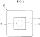
Fig. 6 is a bottom view of the biomedical electrode. - An embodiment of a wearable electrode according to the present invention will be described below with reference to
Figs. 1 to 6 . - As shown in
Figs. 1 and2 , awearable electrode 1 according to the embodiment includes abiomedical electrode 10 having a male button (a locked section; a button) 11 and an undergarment (a garment) 30 having a female button (a locking section) 31 which is detachably locked to themale button 11. Note that a dot button (a snap button) 21 is constituted of themale button 11 and thefemale button 31. -
Fig. 1 illustrates a state in which a standing user (a living body) P is clothed in thewearable electrode 1. InFig. 2 , anouter member 33 which will be described below is not illustrated and a reinforcingfabric 36, a part of which is cut along a break line M, is illustrated. - First, the
biomedical electrode 10 will be described below. - As shown in
Figs. 3 to 5 , thebiomedical electrode 10 according to the embodiment includes anelectrode 13 formed in a flat plate shape, awaterproof layer 14 stacked on theelectrode 13, and the above-describedmale button 11 fixed to theelectrode 13 and awaterproof layer 14. Note that, inFig. 5 , acover 19 which will be described below is indicated by an alternate long and two short dashed line. - The
electrode 13 is formed of a conductive fiber structure obtained by impregnating a fiber structure as foundation cloth serving as cloth which is a base thereof with conductive polymers. - Examples of a form of the fiber structure used for the
electrode 13 include woven fabrics, knitted fabrics, and nonwoven fabrics. When the amount of conductive resins (conductive polymers) to be impregnated into the fiber structure is insufficient, since washing durability in repeated use is not obtained, a base weight of the fiber structure (a unit weight of the foundation cloth) is preferably 50 g/m2 or more and 300 g/m2 or less. When the base weight is less than 50 g/m2, the amount of the impregnated conductive resin decreases and thus washing durability cannot be obtained. When the base weight is more than 300 g/m2, the wearability is worse. The base weight is more preferably 60 g/m2 or more and 250 g/m2 or less. - The thickness of the fiber structure is preferably 0.2 mm or more and 2.0 mm or less. When the thickness is less than 0.2 mm, since the cloth is too thin, a substantial based weight decreases and thus the amount of the impregnated conductive resin decreases. When the thickness exceeds 2.0 mm, since the cloth is too thick, the wearability is worse. The thickness is more preferably 0.3 mm or more and 1.5 mm or less.
- Also, in order to continuously obtain good electrocardiographic waveforms, it is necessary to bring the
electrode 13 into contact with skin and maintain an attached state. Since cloth constituting a fiber structure needs to have flexibility in order for theelectrode 13 to be continuously attached to skin, the fiber structure is preferably a woven fabric, a knitted fabric, or a nonwoven fabric, and more preferably a knitted fabric having higher flexibility. Here, when theelectrode 13 is broken or moves during wear because theelectrode 13 itself is too flexible, a member for reinforcement may be disposed on a back side of theelectrode 13. - In addition, tissues and manufacturing methods of fiber structures represented by knitted fabrics are not particularly limited, but a shape of the
electrode 13 is preferably a shape which retains moisture such as sweat and double knits can be preferably used as the knitted fabric. Examples of such tissues include double raschel tissues, cardboard tissues, reversible tissues, smooth tissues, milling tissues, fleeced tissues, and the like, but the present invention is not limited thereto. - Woven or knitted fabrics used for the
electrode 13 of the present invention preferably include multifilament yarns composed of a plurality of monofilaments in view of supporting of a conductive resin in a fiber structure and high conductivity. Fineness of the multifilament yarns is not particularly limited, but the fineness thereof is preferably 30 dtex to 400 dtex in view of taking advantage of characteristics of the fiber structure. The mixing ratio of multifilament yarns in the woven or knitted fabric is not particularly limited as long as the mixing ratio does not affect performance of the fiber structure, but the mixing ratio thereof is preferably a higher mixing ratio in view of conductivity and durability and more preferably 50% or more and 100% or less. - Examples of materials of the multifilament yarn used for the woven or knitted fabric include polyester synthetic fibers such as polyethylene terephthalate, polytrimethylene terephthalate, and polybutylene terephthalate, and polyamide-based synthetic fibers such as nylon, and the like, but the present invention is not limited thereto. Furthermore, materials obtained by blending additives such as titanium oxide into the woven or knitted fabric may be used and fibers modified with polymers used to give functionality such as hygroscopicity improvement may also be used.
- Also, cross-sectional shapes of unit monofilaments constituting multifilaments are not limited, and yarns with various different cross-sectional shapes represented by circular shapes, triangular shapes, octagonal shapes, flat shapes, and Y shapes can also be used. As non-elastic yarns, core sheaths or side-by-side type composite yarns composed of polymers with different viscosities can also be used. False twisted yarns obtained by performing false twisting on raw yarns may also be used. Synthetic fibers of polyacrylonitrile, polypropylene, and the like, regenerated fibers of rayon, polynosic, cupra, and the like, semisynthetic fibers of acetate, triacetate, and the like, and natural fibers represented by silk can be used.
- The fiber structure according to the present invention preferably includes multifilaments composed of monofilaments with filament diameters of 0.2 dtex or less in view of supporting of conductive resins on fiber surfaces and in voids between fibers. The mixing ratio of the monofilament multifilaments of 0.2 dtex or less in the fiber structure is not particularly limited as long as the mixing ratio does not affect performance of the fiber structure, but the mixing ratio is preferably a high mixing ratio in view of conductivity and durability and more preferably 50% or more and 100% or less.
- In addition, as the number of monofilaments increases, voids formed by a plurality of monofilaments, that is, the sizes of portions carrying conductive resins, decrease, so that performance of supporting conductive resins in a fiber structure increases and excellent high conductivity and washing durability can be obtained because continuity of conductive resins is maintained even when the sizes of portions carrying conductive resins are decreased by decreasing filament diameters.
- Microfibers with filament diameters of 5 µm or less used for artificial leathers, outer materials, or the like are preferably used, and nanofibers with filament diameters of 10 nm or more and 1000 nm or less that have been used in recent years for the purpose of preventing slipping of linings of sports clothes, brassieres, golf gloves, and the like are more preferably used.
- Fiber structures including nanofiber staple yarn assemblies prepared from "Nanoalloy (registered trademark)" fibers, monofilament yarn assemblies prepared using an electrospinning method and the like, and nanofibers prepared using a known method can be appropriately used for nanofibers, but fiber structures including multifilament yarns of nanofibers are more desirable.
- The multifilament yarns of the nanofibers can be prepared using a known composite spinning method or the like.
- For example, nanofiber multifilament yarns, in which variations in filament diameters are small, obtained by performing sea component removal treatment on composite fibers using a composite spinneret disclosed in Japanese Examined Patent Application, First Publication No.
2013-185283 - As the conductive polymer, conductive polymers containing a mixture of poly3,4-ethylenedioxythiophene and polystyrene sulfonic acid (PEDOT-PSS) can be appropriately used.
- Besides this, examples of the conductive polymers include pyrrole-based, thiophene-based, isothianaphthene-based, phenylene-based, acetylene-based, and aniline-based conductive polymers, copolymers thereof, or the like. In addition, examples of dopants of the conductive polymers may be at least one type of ion of polymer ions such as halide ions, perchlorate ions, tetrafluoroborate ions, hexafluoroarsenate ions, sulfate ions, nitrate ions, thiocyanate ions, phosphate ions, trifluoroacetate ions, tosylate ions, alkylsulfonate ions, and polyacrylate ions.
- The
electrode 13 having the fiber structure according to the present invention has low irritation and high safety when in contact with skin. When a signal cannot be satisfactorily obtained due to drying of skin or the like, it is desirable to apply a small amount of physiological saline or humectant to the fiber structure. Examples of the humectant include glycerol, sorbitol, polyethylene glycol, polyethylene glycol-polypropylene glycol copolymers, ethylene glycol, sphingosine, phosphatidylcholine, and the like, and one of these may be independently used or two or more of these may be used in combination. - By moisturizing the
electrode 13 as described above, when theelectrode 13 comes into contact with skin of a user P, an adhesive force occurs due to wettability of the humectant. - More specifically, the
electrode 13 is obtained by impregnating the fiber structure with a conductive polymer by applying a liquid dispersion, which is obtained by dispersing the above-described conductive polymer and a binder in a solvent, to the above-described fiber structure. - The type of solvent is not particularly limited and is appropriately selected in accordance with types and purposes of conductive polymers or binders.
- The conductive polymer is used with a binder to increase scratch resistance or a surface hardness of a coating film containing conductive polymer and improve adhesion to a base material. Furthermore, with use of the binder, it becomes easy to support the conductive polymer on a fiber structure and thus increase in surface resistance after an electrode member has been subjected to repeated washing can also be minimized.
- A binder may be a thermosetting resin or a thermoplastic resin. Examples of the binder include: polyesters such as polyethylene terephthalate, polybutylene terephthalate, and polyethylene naphthalate; polyimides; polyamide imides; polyamides such as polyamide 6, polyamide 6,6, polyamide 12, and
polyamide 11; fluororesins such as polyvinylidene fluoride, polyvinyl fluoride, polytetrafluoroethylene, ethylene tetrafluoroethylene copolymers, and polychlorotrifluoroethylene; vinyl resins such as polyvinyl alcohol, polyvinyl ether, polyvinyl butyral, polyvinyl acetate, and polyvinyl chloride; epoxy resins; xylene resins; aramid resins; polyimide silicones; polyurethanes; polyureas; melamine resins; phenol resins; polyethers; acrylic resins; copolymers thereof, and the like. - Such a binder may be dissolved in an organic solvent, may be subject to a reaction with a functional group such as a sulfonic acid group or a carboxylic acid group to form an aqueous solution, and may be dispersed in water through emulsification or the like.
- Among binder resins, one or more of polyurethanes, polyester, acrylic resins, polyamide, polyimide, epoxy resins, and polyimide silicones are desirable because these binder resins can be easily mixed in. The solvent to be used is not limited as long as the solvent can stably disperse a conductive polymer and a binder, but water or a mixed solution of water and alcohol can be appropriately used. When a polythiophene-based conductive polymer such as PEDOT-PSS is used, it is desirable to use a mixed solvent of water and ethanol.
- The size or a shape of the
electrode 13 is not particularly limited as long as a biological signal can be detected and vertical and horizontal lengths are preferably 2 cm or more and 20 cm or less. When the vertical and horizontal lengths of theelectrode 13 are less than 2 cm, since an area of theelectrode 13 is too small, theelectrode 13 is also easily deviated and easily picks up noise when garments move during exercise or the like. When the vertical and horizontal lengths thereof exceed 20 cm, since it is not the size required for actual signal detection and the area of theelectrode 13 is too large, an interval between neighboring electrodes is small, which easily causes trouble such as short-circuiting. - The vertical and horizontal lengths thereof are more preferably 2.5 cm or more and 18 cm or less. As shown in
Fig. 6 , for example, an electrode having a square shape of about 4 cm x about 4 cm and a shape with rounded corners is more preferably used. - The
waterproof layer 14 is a layer through which liquid moisture does not pass. - The
waterproof layer 14 mentioned herein is not necessarily required and is preferably stacked on one surface of a fiber structure containing a conductive substance as a resin layer. It is desirable to stack a resin layer on a back surface side of a surface coming into contact with a skin side of a fiber structure used for theelectrode 13 in consideration of applications to a living body electrode. When a biological signal is detected, it is difficult to detect the biological signal stably when theelectrode 13 dries. - Therefore, because it is necessary to maintain the
electrode 13 in a wet state to some extent, one surface of theelectrode 13 is covered with a resin layer so that drying thereof can be prevented and thus conductivity can be stably obtained. In addition, one surface of theelectrode 13 is covered with a resin layer so that falling-off of a conductive resin during washing can be reduced and thus washing durability can be significantly improved. - The type and the shape of a polymer constituting the resin layer are not particularly limited as long as the polymer is a polymer through which a liquid does not pass, and for example, a method of laminating a polymer film of acryl, vinyl chloride, or the like, a method of coating acrylic resins or urethane resins, and the like can be provided. Although a polymer layer is not particularly limited, when it is necessary to moderately control a feeling of stickiness in the skin, the polymer layer is preferably a waterproof moisture-permeable layer.
- Examples of the waterproof moisture-permeable layer include forms obtained by stacking polytetrafluoroethylene (PTFE) porous membranes, non-porous membranes made of hydrophilic elastomers such as hydrophilic polyester resins and polyurethane resins, polyurethane resin microporous membranes, or the like, known membranes, films, stacked articles, resins or the like using a coating or laminating method, but the present invention is not limited thereto. The
waterproof layer 14 is preferably bonded in a stacked manner by laminating a polyurethane resin microporous membrane with elasticity in view of followability to a fiber structure which is a base material. In addition, in order to improve moisture permeability, microporosity may be formed in a fiber structure obtained by stacking a resin layer on one surface thereof using a punching machine or a sewing machine. - The
male button 11 has a known constitution and includes apost 16 and astud 17 as illustrated in the enlarged diagram inFig. 1 . Thepost 16 and thestud 17 are formed of metals which are conductive such as stainless steel. Thepost 16 is disposed on theelectrode 13 side and thestud 17 is disposed on thewaterproof layer 14 side. A part of thepost 16 is embedded in theelectrode 13 and a part of thestud 17 is embedded in thewaterproof layer 14. For this reason, a step formed by theelectrode 13 and thepost 16 and a step formed by thewaterproof layer 14 and thestud 17 decrease. - A
head section 16a of thepost 16 protrudes to the outside via thestud 17. Thepost 16 and thestud 17 are electrically connected to each other. Themale button 11 is provided on center portions of theelectrode 13 and thewaterproof layer 14, but installation positions of themale button 11 is not particularly limited. Themale button 11 is electrically connected to theelectrode 13. - The
male button 11 is mechanically connected to theundergarment 30 and thebiomedical electrode 10, supports a center portion of thebiomedical electrode 10 at one point, and electrically connects thebiomedical electrode 10 to a measuring device (a processing device) D via afemale button 31. - The
post 16 of themale button 11 is preferably covered with the cover (a coating member) 19. - The
cover 19 is not particularly limited as long as thepost 16 does not come into direct contact with the user P, but seam tapes or the like which are usually used for clothes can be used. Note that, although it is assumed that the coating member is thecover 19, the coating member may be a coating or the like configured to cover an outer surface of thepost 16 in contact with the user P. - As shown in
Figs. 1 and2 , theundergarment 30 includes theouter member 33, a backingmember 34 connected to theouter member 33, and awiring section 35 provided in the backingmember 34. Theouter member 33 and the backingmember 34 can be formed desired fabrics or the like. Aslit 34a extending in a vertical direction is formed in the backingmember 34. Theslit 34a passes through the backingmember 34 in a thickness direction. A length L of theslit 34a in the vertical direction is preferably shorter than a length of a short side of thebiomedical electrode 10. For example, when thebiomedical electrode 10 is a 4 cm square, the length thereof is less than 4 cm (refer toFig. 2 ). The width of theslit 34a is not particularly limited as long as thehead section 16a of thepost 16 is movable along theslit 34a, but a width of theslit 34a is preferably about an outer circumference of thehead section 16a. - The
slit 34a is preferably formed in a position facing a chest P1 of the user P when the user P is clothed in thewearable electrode 1. - The reinforcing
fabric 36 may be provided between the backingmember 34 and theouter member 33. For example, the reinforcingfabric 36 is formed in a rectangular shape using a desired fabrics or the like. The reinforcingfabric 36 is disposed to cover theslit 34a of the backingmember 34. The backingmember 34 and the reinforcingfabric 36 are connected, for example, by a pair ofstitches 37 formed by stitching the backingmember 34 and the reinforcingfabric 36 using threads. Thestitches 37 extend in a vertical direction. The backingmember 34, theslit 34a, the reinforcingfabric 36, and the pair ofstitches 37 configured in this way constitutetubular structure 38. - The
outer member 33 and the backingmember 34 are connected to aconnection section 40 such as stitches provided above the reinforcingfabric 36. As will be described below, thebiomedical electrode 10 is attached to the backingmember 34 via theslit 34a. It is assumed that a part which is closest to theslit 34a in a part to which thebacking member 34 and theouter member 33 are connected is theconnection section 40. Theconnection section 40 is away from theslit 34a of the backingmember 34 and the separated distance is preferably 1 cm or more. This is because movement of theouter member 33 is not easily transferred to thebiomedical electrode 10 via theconnection section 40 as will be described below. - An
annular loop section 41 may be attached to a part above the reinforcingfabric 36 in the backingmember 34. - The
wiring section 35 includes asupport plate 44 disposed in thetubular structure 38, thefemale button 31, which have been described above, fixed to a center portion of thesupport plate 44, and aconnection wiring 45 having a first end portion connected to thefemale button 31. - The
support plate 44 is formed in a rectangular shape using a desired resinous plate material, fabric, or the like. Thesupport plate 44 preferably has certain rigidity to be able to easily move in thetubular structure 38. A width of thesupport plate 44 is shorter than a distance between the pair of stitches 37. Thesupport plate 44 is vertically movable in thetubular structure 38 using the pair ofstitches 37 as guides. - The position of the
support plate 44 in a vertical direction is maintained by a frictional force occurring between thesupport plate 44 and the backingmember 34 and the reinforcingfabric 36. - The
female button 31 is of a known constitution provided in theundergarment 30 and includes ahead 47 and asocket 48. Thehead 47 and thesocket 48 are formed of metals which are conductive such as stainless steel. Thehead 47 is disposed on the reinforcingfabric 36 side and thesocket 48 is disposed on the backingmember 34 side. Thehead 47 and thesocket 48 are electrically connected to each other. - The
head section 16a of themale button 11 via theslit 34a of the backingmember 34 can be locked to thefemale button 31. Thefemale button 31 and themale button 11 of thebiomedical electrode 10 disposed to sandwich theslit 34a are locked to each other to be integrated and vertically move along theslit 34a. Thus, the position of thebiomedical electrode 10 in the vertical direction with respect to the chest P1 is optimized and a biological signal can be measured. - When the
male button 11 and thefemale button 31 are locked to each other, themale button 11 and thefemale button 31 are electrically connected together. - As the
connection wiring 45, a well-known wiring such as a so-called flexible wiring in which the wiring is soft can be appropriately selected and used. Discomfort of the user P experiencing due to a local load applied to the chest P1 can be suppressed using the flexible wiring. - A core wire (not shown) of the
connection wiring 45 is electrically connected to thefemale button 31. Theconnection wiring 45 is drawn upward from thefemale button 31, passes through theloop section 41, and then is routed downward. A second end portion of theconnection wiring 45 is connected to the measuring device D. - The measuring device D has a known constitution capable of processing an electric biological signal emitted by the user P.
- For example, the measuring device D is held in an
accommodation section 33a such as a pocket provided in theouter member 33. The measuring device D may be held in an accommodation section provided in the backingmember 34, a waist bag attached to the user P, or the like. - An action of the
wearable electrode 1 configured as described above will be described below. - The user P performs washing or the like of the
undergarment 30 obtained by removing thebiomedical electrode 10. Awearable electrode 1 is constituted by locking themale button 11 of the washedbiomedical electrode 10 to thefemale button 31 of theundergarment 30. - At this time, the
female button 31 and themale button 11 are electrically connected to each other. - When the user P is clothed in the
undergarment 30 of thewearable electrode 1, theelectrode 13 of thebiomedical electrode 10 comes into contact with the skin of the chest P1 of the user P. Since theelectrode 13 is easily deformed, theelectrode 13 is easily deformed in accordance with a shape of the chest P1 and a biological signal emitted by the user P is easily acquired by theelectrode 13. - Since the
cover 19 is provided on thebiomedical electrode 10, themale button 11 does not come into direct contact with the chest P1 and thus the user P is less likely to feel uncomfortable against thebiomedical electrode 10 in contact with the chest P1. - Since moisture passes through the
waterproof layer 14 when thewaterproof layer 14 is set to be a waterproof moisture-permeable layer, the chest P1 is not easily warmed up. - The sticking effect of the
biomedical electrode 10 to skin due to wettability and viscosity thereof is stabilized when the following four conditions are satisfied. Firstly, thebiomedical electrode 10 is brought into contact with skin in parallel (flat). Secondly, thebiomedical electrode 10 is supported at a center portion of thebiomedical electrode 10 and is pressed toward skin. Thirdly, thebiomedical electrode 10 is not deviated (not shifted) on skin. Fourthly, humectants is not let be lost (by dry diffusion or the like). - Examples of factors causing failure or interruption of measurement due to the loss of the above-described four conditions include a force (horizontal and vertical forces) of peeling off the
biomedical electrode 10 from a skin surface, skin deformation due to movement of a body, and loss of humectants (due to drying or the like). The force of peeling off thebiomedical electrode 10 and the skin deformation due to the movement of the body lead to poor contact between skin and thebiomedical electrode 10. Loss of humectants leads to an increase in contact resistance. Particularly, measurement is impaired due to large movement of his or her body, theconnection wiring 45 of thebiomedical electrode 10, and pulling by an undergarment in the related art in many cases. - The user P appropriately moves the
biomedical electrode 10 in a vertical direction according to necessity to adjust a position of thebiomedical electrode 10. - A biological signal acquired by the
electrode 13 of thebiomedical electrode 10 is transmitted to the measuring device D via themale button 11, thefemale button 31, and theconnection wiring 45 which are electrically connected to each other. - When the measuring device D starts up, measurement of biological signals of electrodcardiographic waveforms or the like is started. The user P performs an operation such as walking while measuring an electrocardiogram.
- The
outer member 33 of theundergarment 30 moves along with the user P's motion in some cases. Since theconnection section 40 is away from theslit 34a of the backingmember 34, movement of theouter member 33 is hardly transferred to theslit 34a of the backingmember 34 via theconnection section 40. For this reason, a state in which theelectrode 13 of thebiomedical electrode 10 comes into contact with the chest P1 of the user P is maintained. - When the
connection wiring 45 serving as a part near the measuring device D is pulled, a force acting on theconnection wiring 45 is received by theloop section 41 and then transmitted to thefemale button 31. Thus, a force pulling theconnection wiring 45 is suppressed from being directly transmitted to thefemale button 31. - As described above, according to the
biomedical electrode 10 and thewearable electrode 1 of the embodiment, thebiomedical electrode 10 can be easily attached to and detached from theundergarment 30 due to themale button 11 and thefemale button 31. Furthermore, a biological signal acquired by theelectrode 13 in contact with the user P can be transmitted to thefemale button 31 via themale button 11. - The center portion of the
biomedical electrode 10 is supported by thefemale button 31 on theundergarment 30 side. Thedot button 21 can press thebiomedical electrode 10 toward skin while maintaining electrical contact to thebiomedical electrode 10 and thus can keep a state in which theelectrode 13 of thebiomedical electrode 10 is attached to the skin. - Also, since a stable contact state to skin can be maintained as long as an adhesive force between the
electrode 13 and the chest P1 is not lost, long-term measurement of a biological signal is possible. - The
biomedical electrode 10 includes thecover 19 so that the user P is less likely to feel uncomfortable and discomfort against thebiomedical electrode 10 in contact with the chest P1. Thebiomedical electrode 10 reduces a local load applied to the user P's body so that the user P has almost no uncomfortable during wearing and thus long-term measurement can be performed. A part of themale button 11 is embedded in theelectrode 13 so that a step formed by theelectrode 13 and themale button 11 decreases. Therefore, the user P in contact with theelectrode 13 is less likely to feel uncomfortable. Theelectrode 13 is formed of a conductive fiber structure which is a fiber structure obtained by impregnating conductive polymers. For this reason, theelectrode 13 is easily deformed in accordance with the shape of the chest P1 so that theelectrode 13 can reliably acquire a biological signal from the chest P1. - Although the embodiment of the present invention has been described in detail above with reference to the drawings, a specific constitution is not limited to such an embodiment and also includes a design or the like within the scope which does not depart from the gist of the present invention.
- For example, in the embodiment, it is assumed that a locked section is the
male button 11 and a locking section is thefemale button 31. However, it may be assumed that a locked section is a female button and a locking section is a male button. - It is assumed that a locking section and a locked section corresponds to the
dot button 21. However, a locking section and a locked section may be other connection structures, buttons, or the like such as a snap fit as long as the locking section and the locked section which is conductive and are easily attached and detached. - In the embodiment, it is assumed that the measuring device D configured to display an electrocardiogram is electrically connected to the
female button 31 via theconnection wiring 45. However, a device connected to thefemale button 31 is not limited thereto and may be, for example, a device capable of performing processing such as detection and display of a biological signal and a device configured to transmit a biological signal to an external device through wireless communication or the like. - According to the present invention, a biomedical electrode and a wearable electrode capable of transmitting a biological signal and being easily attached to and detached from a garment can be provided.
-
- 1
- Wearable electrode
- 10
- Biomedical electrode
- 11
- Male button (locked section)
- 13
- Electrode
- 19
- Cover (coating member)
- 21
- Dot button
- 30
- Undergarment (garment)
- 31
- Female button (locking section)
Claims (8)
- A biomedical electrode which is detachably attached to a garment, the biomedical electrode comprising:an electrode coming into contact with a living body clothed in the garment to acquire a biological signal emitted by the living body; anda locked section which is conductive and electrically connected to the electrode, the locked section being detachably locked to a locking section which is conductive and provided in the garment, wherein the locked section is electrically connected to the locking section when locked to the locking section.
- The biomedical electrode according to claim 1, comprising a coating member configured to cover the locked section.
- The biomedical electrode according to claim 1, wherein at least a part of the locked section is embedded in the electrode.
- The biomedical electrode according to claim 1, wherein the locked section is a button.
- The biomedical electrode according to claim 4, wherein the button is a male button or a female button of a dot button.
- A wearable electrode comprising:the biomedical electrode according to any one of claims 1 to 5; andthe garment,wherein the electrode is formed of a conductive fiber structure which is a fiber structure impregnated with a conductive polymer.
- The wearable electrode according to claim 6, wherein the conductive fiber structure is obtained by impregnating the fiber structure with a conductive polymer by applying a liquid dispersion, which is obtained by dispersing the conductive polymer and a binder in a solvent, to the fiber structure.
- The wearable electrode according to claim 6, wherein the conductive polymer includes a mixture of poly3,4-ethylenedioxythiophene and polystyrene sulfonic acid.
Applications Claiming Priority (2)
| Application Number | Priority Date | Filing Date | Title |
|---|---|---|---|
| JP2015137286 | 2015-07-08 | ||
| PCT/JP2016/070280 WO2017007021A1 (en) | 2015-07-08 | 2016-07-08 | Biomedical electrode and wearable electrode |
Publications (3)
| Publication Number | Publication Date |
|---|---|
| EP3287071A1 true EP3287071A1 (en) | 2018-02-28 |
| EP3287071A4 EP3287071A4 (en) | 2018-11-21 |
| EP3287071B1 EP3287071B1 (en) | 2020-11-25 |
Family
ID=57685656
Family Applications (1)
| Application Number | Title | Priority Date | Filing Date |
|---|---|---|---|
| EP16821489.8A Active EP3287071B1 (en) | 2015-07-08 | 2016-07-08 | Biomedical electrode and wearable electrode |
Country Status (5)
| Country | Link |
|---|---|
| US (1) | US10772524B2 (en) |
| EP (1) | EP3287071B1 (en) |
| JP (2) | JPWO2017007021A1 (en) |
| CN (1) | CN107708542B (en) |
| WO (1) | WO2017007021A1 (en) |
Families Citing this family (12)
| Publication number | Priority date | Publication date | Assignee | Title |
|---|---|---|---|---|
| WO2018180629A1 (en) * | 2017-03-30 | 2018-10-04 | 東レ株式会社 | Antenna, wireless communication device, biometric signal measurement device, and garment |
| EP3407228B1 (en) | 2017-05-26 | 2024-03-27 | Nokia Technologies Oy | Wearable sensors for inputting a command |
| JP6934380B2 (en) * | 2017-09-26 | 2021-09-15 | 倉敷紡績株式会社 | Clothes for acquiring biological signals |
| CN107669259A (en) * | 2017-09-27 | 2018-02-09 | 联想(北京)有限公司 | A kind of electrocardio clothing |
| JP7031319B2 (en) * | 2018-01-15 | 2022-03-08 | 東洋紡株式会社 | clothing |
| JP2019126562A (en) * | 2018-01-25 | 2019-08-01 | 日本電信電話株式会社 | Wearable device |
| JP6948272B2 (en) * | 2018-01-30 | 2021-10-13 | 信越ポリマー株式会社 | Method of manufacturing conductive fabric |
| JP6966389B2 (en) * | 2018-07-12 | 2021-11-17 | 信越化学工業株式会社 | Bioelectrode composition, bioelectrode, and method for manufacturing bioelectrode |
| JP6966396B2 (en) * | 2018-08-23 | 2021-11-17 | 信越化学工業株式会社 | Bioelectrode composition, bioelectrode, and method for manufacturing bioelectrode |
| CN110584620A (en) * | 2019-09-09 | 2019-12-20 | 深圳创达云睿智能科技有限公司 | Wearable device |
| US11380212B2 (en) | 2020-05-21 | 2022-07-05 | Setcan Corporation | Garment supported electrode |
| CN115109365A (en) * | 2022-06-10 | 2022-09-27 | 重庆大学 | Double-network PEDOT flexible conductive polymer and preparation method thereof |
Family Cites Families (22)
| Publication number | Priority date | Publication date | Assignee | Title |
|---|---|---|---|---|
| CA1111503A (en) * | 1977-04-02 | 1981-10-27 | Isoji Sakurada | Biomedical electrode |
| US5157058A (en) * | 1987-01-05 | 1992-10-20 | Tetratec Corporation | Microporous waterproof and moisture vapor permeable structures, processes of manufacture and useful articles thereof |
| JPH03234871A (en) * | 1990-02-07 | 1991-10-18 | Achilles Corp | Electrically conductive woven fabric and its preparation |
| JPH0647012A (en) | 1992-07-30 | 1994-02-22 | Kanai Hiroyuki | Bioelectrode |
| JP3618155B2 (en) | 1995-11-06 | 2005-02-09 | コーリンメディカルテクノロジー株式会社 | Pressure band for blood pressure measurement |
| US6970731B1 (en) | 1998-09-21 | 2005-11-29 | Georgia Tech Research Corp. | Fabric-based sensor for monitoring vital signs |
| JP3711236B2 (en) * | 2000-11-24 | 2005-11-02 | フクダ電子株式会社 | Bioelectric signal induction sensor and bioelectric signal recording system |
| GB0130608D0 (en) | 2001-12-21 | 2002-02-06 | Psimedica Ltd | Medical fibres and fabrics |
| JP3104124U (en) | 2004-03-19 | 2004-09-02 | 京都医療技術開発株式会社 | Low frequency treatment device |
| KR100734986B1 (en) * | 2005-09-23 | 2007-07-06 | 한국전자통신연구원 | Garment for physiological signal measurement |
| US8527028B2 (en) | 2007-05-16 | 2013-09-03 | Medicomp, Inc. | Harness with sensors |
| JP5434356B2 (en) | 2009-08-17 | 2014-03-05 | 日本電気株式会社 | Biological electrode |
| US8475371B2 (en) | 2009-09-01 | 2013-07-02 | Adidas Ag | Physiological monitoring garment |
| CN101845753B (en) | 2010-05-14 | 2012-06-06 | 苏州新纶超净技术有限公司 | Anti-static/conductive fabric and manufacture method thereof |
| RU2570283C2 (en) | 2010-11-17 | 2015-12-10 | Смарт Солюшнз Текнолоджиз, С.Л. | Sensor for receiving physiological signals |
| US10153065B2 (en) | 2011-11-17 | 2018-12-11 | Nippon Telegraph And Telephone Corporation | Conductive polymer fibers, method and device for producing conductive polymer fibers, biological electrode, device for measuring biological signals, implantable electrode, and device for measuring biological signals |
| WO2013075270A1 (en) | 2011-11-25 | 2013-05-30 | Yang Chang-Ming | Object, method, and system for detecting heartbeat or whether or not electrodes are in proper contact |
| JP5984645B2 (en) * | 2012-11-30 | 2016-09-06 | 日本電信電話株式会社 | Pressure sensor and pressure sensor device |
| JP6271856B2 (en) * | 2013-04-17 | 2018-01-31 | 帝人株式会社 | Fabric manufacturing method and textile manufacturing method |
| JP6073745B2 (en) | 2013-05-23 | 2017-02-01 | 日本電信電話株式会社 | Bioelectrode and clothing |
| CN103462602B (en) | 2013-09-30 | 2015-07-08 | 东华大学 | Preparation method of spinning electrode used for testing electrocardiosignal |
| JP6073776B2 (en) * | 2013-11-28 | 2017-02-01 | 日本電信電話株式会社 | Bioelectric signal monitor clothing |
-
2016
- 2016-07-08 CN CN201680037044.9A patent/CN107708542B/en active Active
- 2016-07-08 EP EP16821489.8A patent/EP3287071B1/en active Active
- 2016-07-08 WO PCT/JP2016/070280 patent/WO2017007021A1/en active Application Filing
- 2016-07-08 JP JP2017527512A patent/JPWO2017007021A1/en active Pending
- 2016-07-08 US US15/577,512 patent/US10772524B2/en active Active
-
2019
- 2019-10-01 JP JP2019181672A patent/JP6856724B2/en active Active
Also Published As
| Publication number | Publication date |
|---|---|
| EP3287071B1 (en) | 2020-11-25 |
| CN107708542A (en) | 2018-02-16 |
| JP6856724B2 (en) | 2021-04-07 |
| WO2017007021A1 (en) | 2017-01-12 |
| JP2020062393A (en) | 2020-04-23 |
| US10772524B2 (en) | 2020-09-15 |
| CN107708542B (en) | 2021-01-15 |
| US20180146873A1 (en) | 2018-05-31 |
| JPWO2017007021A1 (en) | 2018-03-29 |
| EP3287071A4 (en) | 2018-11-21 |
Similar Documents
| Publication | Publication Date | Title |
|---|---|---|
| EP3287071B1 (en) | Biomedical electrode and wearable electrode | |
| EP3298960B1 (en) | Wearable electrode | |
| JP6704949B2 (en) | Biological signal detection clothing | |
| JP7079199B2 (en) | Biological signal detection clothing | |
| CN105939659A (en) | Electrode member and device | |
| US10835141B2 (en) | Wearable electrode |
Legal Events
| Date | Code | Title | Description |
|---|---|---|---|
| STAA | Information on the status of an ep patent application or granted ep patent |
Free format text: STATUS: THE INTERNATIONAL PUBLICATION HAS BEEN MADE |
|
| PUAI | Public reference made under article 153(3) epc to a published international application that has entered the european phase |
Free format text: ORIGINAL CODE: 0009012 |
|
| STAA | Information on the status of an ep patent application or granted ep patent |
Free format text: STATUS: REQUEST FOR EXAMINATION WAS MADE |
|
| 17P | Request for examination filed |
Effective date: 20171124 |
|
| AK | Designated contracting states |
Kind code of ref document: A1 Designated state(s): AL AT BE BG CH CY CZ DE DK EE ES FI FR GB GR HR HU IE IS IT LI LT LU LV MC MK MT NL NO PL PT RO RS SE SI SK SM TR |
|
| AX | Request for extension of the european patent |
Extension state: BA ME |
|
| DAV | Request for validation of the european patent (deleted) | ||
| DAX | Request for extension of the european patent (deleted) | ||
| A4 | Supplementary search report drawn up and despatched |
Effective date: 20181024 |
|
| RIC1 | Information provided on ipc code assigned before grant |
Ipc: A61B 5/0478 20060101ALI20181018BHEP Ipc: A61B 5/0408 20060101AFI20181018BHEP |
|
| STAA | Information on the status of an ep patent application or granted ep patent |
Free format text: STATUS: EXAMINATION IS IN PROGRESS |
|
| 17Q | First examination report despatched |
Effective date: 20190715 |
|
| GRAP | Despatch of communication of intention to grant a patent |
Free format text: ORIGINAL CODE: EPIDOSNIGR1 |
|
| STAA | Information on the status of an ep patent application or granted ep patent |
Free format text: STATUS: GRANT OF PATENT IS INTENDED |
|
| INTG | Intention to grant announced |
Effective date: 20200625 |
|
| GRAS | Grant fee paid |
Free format text: ORIGINAL CODE: EPIDOSNIGR3 |
|
| GRAA | (expected) grant |
Free format text: ORIGINAL CODE: 0009210 |
|
| STAA | Information on the status of an ep patent application or granted ep patent |
Free format text: STATUS: THE PATENT HAS BEEN GRANTED |
|
| AK | Designated contracting states |
Kind code of ref document: B1 Designated state(s): AL AT BE BG CH CY CZ DE DK EE ES FI FR GB GR HR HU IE IS IT LI LT LU LV MC MK MT NL NO PL PT RO RS SE SI SK SM TR |
|
| REG | Reference to a national code |
Ref country code: GB Ref legal event code: FG4D |
|
| REG | Reference to a national code |
Ref country code: DE Ref legal event code: R079 Ref document number: 602016048723 Country of ref document: DE Free format text: PREVIOUS MAIN CLASS: A61B0005040800 Ipc: A61B0005280000 |
|
| REG | Reference to a national code |
Ref country code: CH Ref legal event code: EP |
|
| REG | Reference to a national code |
Ref country code: AT Ref legal event code: REF Ref document number: 1337337 Country of ref document: AT Kind code of ref document: T Effective date: 20201215 |
|
| REG | Reference to a national code |
Ref country code: DE Ref legal event code: R096 Ref document number: 602016048723 Country of ref document: DE |
|
| REG | Reference to a national code |
Ref country code: IE Ref legal event code: FG4D |
|
| REG | Reference to a national code |
Ref country code: AT Ref legal event code: MK05 Ref document number: 1337337 Country of ref document: AT Kind code of ref document: T Effective date: 20201125 |
|
| REG | Reference to a national code |
Ref country code: NL Ref legal event code: MP Effective date: 20201125 |
|
| PG25 | Lapsed in a contracting state [announced via postgrant information from national office to epo] |
Ref country code: FI Free format text: LAPSE BECAUSE OF FAILURE TO SUBMIT A TRANSLATION OF THE DESCRIPTION OR TO PAY THE FEE WITHIN THE PRESCRIBED TIME-LIMIT Effective date: 20201125 Ref country code: GR Free format text: LAPSE BECAUSE OF FAILURE TO SUBMIT A TRANSLATION OF THE DESCRIPTION OR TO PAY THE FEE WITHIN THE PRESCRIBED TIME-LIMIT Effective date: 20210226 Ref country code: PT Free format text: LAPSE BECAUSE OF FAILURE TO SUBMIT A TRANSLATION OF THE DESCRIPTION OR TO PAY THE FEE WITHIN THE PRESCRIBED TIME-LIMIT Effective date: 20210325 Ref country code: RS Free format text: LAPSE BECAUSE OF FAILURE TO SUBMIT A TRANSLATION OF THE DESCRIPTION OR TO PAY THE FEE WITHIN THE PRESCRIBED TIME-LIMIT Effective date: 20201125 Ref country code: NO Free format text: LAPSE BECAUSE OF FAILURE TO SUBMIT A TRANSLATION OF THE DESCRIPTION OR TO PAY THE FEE WITHIN THE PRESCRIBED TIME-LIMIT Effective date: 20210225 |
|
| PG25 | Lapsed in a contracting state [announced via postgrant information from national office to epo] |
Ref country code: AT Free format text: LAPSE BECAUSE OF FAILURE TO SUBMIT A TRANSLATION OF THE DESCRIPTION OR TO PAY THE FEE WITHIN THE PRESCRIBED TIME-LIMIT Effective date: 20201125 Ref country code: IS Free format text: LAPSE BECAUSE OF FAILURE TO SUBMIT A TRANSLATION OF THE DESCRIPTION OR TO PAY THE FEE WITHIN THE PRESCRIBED TIME-LIMIT Effective date: 20210325 Ref country code: PL Free format text: LAPSE BECAUSE OF FAILURE TO SUBMIT A TRANSLATION OF THE DESCRIPTION OR TO PAY THE FEE WITHIN THE PRESCRIBED TIME-LIMIT Effective date: 20201125 Ref country code: LV Free format text: LAPSE BECAUSE OF FAILURE TO SUBMIT A TRANSLATION OF THE DESCRIPTION OR TO PAY THE FEE WITHIN THE PRESCRIBED TIME-LIMIT Effective date: 20201125 Ref country code: BG Free format text: LAPSE BECAUSE OF FAILURE TO SUBMIT A TRANSLATION OF THE DESCRIPTION OR TO PAY THE FEE WITHIN THE PRESCRIBED TIME-LIMIT Effective date: 20210225 Ref country code: SE Free format text: LAPSE BECAUSE OF FAILURE TO SUBMIT A TRANSLATION OF THE DESCRIPTION OR TO PAY THE FEE WITHIN THE PRESCRIBED TIME-LIMIT Effective date: 20201125 |
|
| REG | Reference to a national code |
Ref country code: LT Ref legal event code: MG9D |
|
| PG25 | Lapsed in a contracting state [announced via postgrant information from national office to epo] |
Ref country code: HR Free format text: LAPSE BECAUSE OF FAILURE TO SUBMIT A TRANSLATION OF THE DESCRIPTION OR TO PAY THE FEE WITHIN THE PRESCRIBED TIME-LIMIT Effective date: 20201125 |
|
| PG25 | Lapsed in a contracting state [announced via postgrant information from national office to epo] |
Ref country code: LT Free format text: LAPSE BECAUSE OF FAILURE TO SUBMIT A TRANSLATION OF THE DESCRIPTION OR TO PAY THE FEE WITHIN THE PRESCRIBED TIME-LIMIT Effective date: 20201125 Ref country code: SM Free format text: LAPSE BECAUSE OF FAILURE TO SUBMIT A TRANSLATION OF THE DESCRIPTION OR TO PAY THE FEE WITHIN THE PRESCRIBED TIME-LIMIT Effective date: 20201125 Ref country code: CZ Free format text: LAPSE BECAUSE OF FAILURE TO SUBMIT A TRANSLATION OF THE DESCRIPTION OR TO PAY THE FEE WITHIN THE PRESCRIBED TIME-LIMIT Effective date: 20201125 Ref country code: EE Free format text: LAPSE BECAUSE OF FAILURE TO SUBMIT A TRANSLATION OF THE DESCRIPTION OR TO PAY THE FEE WITHIN THE PRESCRIBED TIME-LIMIT Effective date: 20201125 Ref country code: RO Free format text: LAPSE BECAUSE OF FAILURE TO SUBMIT A TRANSLATION OF THE DESCRIPTION OR TO PAY THE FEE WITHIN THE PRESCRIBED TIME-LIMIT Effective date: 20201125 Ref country code: SK Free format text: LAPSE BECAUSE OF FAILURE TO SUBMIT A TRANSLATION OF THE DESCRIPTION OR TO PAY THE FEE WITHIN THE PRESCRIBED TIME-LIMIT Effective date: 20201125 |
|
| REG | Reference to a national code |
Ref country code: DE Ref legal event code: R097 Ref document number: 602016048723 Country of ref document: DE |
|
| PG25 | Lapsed in a contracting state [announced via postgrant information from national office to epo] |
Ref country code: DK Free format text: LAPSE BECAUSE OF FAILURE TO SUBMIT A TRANSLATION OF THE DESCRIPTION OR TO PAY THE FEE WITHIN THE PRESCRIBED TIME-LIMIT Effective date: 20201125 |
|
| PLBE | No opposition filed within time limit |
Free format text: ORIGINAL CODE: 0009261 |
|
| STAA | Information on the status of an ep patent application or granted ep patent |
Free format text: STATUS: NO OPPOSITION FILED WITHIN TIME LIMIT |
|
| PG25 | Lapsed in a contracting state [announced via postgrant information from national office to epo] |
Ref country code: AL Free format text: LAPSE BECAUSE OF FAILURE TO SUBMIT A TRANSLATION OF THE DESCRIPTION OR TO PAY THE FEE WITHIN THE PRESCRIBED TIME-LIMIT Effective date: 20201125 Ref country code: NL Free format text: LAPSE BECAUSE OF FAILURE TO SUBMIT A TRANSLATION OF THE DESCRIPTION OR TO PAY THE FEE WITHIN THE PRESCRIBED TIME-LIMIT Effective date: 20201125 |
|
| 26N | No opposition filed |
Effective date: 20210826 |
|
| PG25 | Lapsed in a contracting state [announced via postgrant information from national office to epo] |
Ref country code: SI Free format text: LAPSE BECAUSE OF FAILURE TO SUBMIT A TRANSLATION OF THE DESCRIPTION OR TO PAY THE FEE WITHIN THE PRESCRIBED TIME-LIMIT Effective date: 20201125 |
|
| PG25 | Lapsed in a contracting state [announced via postgrant information from national office to epo] |
Ref country code: ES Free format text: LAPSE BECAUSE OF FAILURE TO SUBMIT A TRANSLATION OF THE DESCRIPTION OR TO PAY THE FEE WITHIN THE PRESCRIBED TIME-LIMIT Effective date: 20201125 |
|
| REG | Reference to a national code |
Ref country code: CH Ref legal event code: PL |
|
| PG25 | Lapsed in a contracting state [announced via postgrant information from national office to epo] |
Ref country code: MC Free format text: LAPSE BECAUSE OF FAILURE TO SUBMIT A TRANSLATION OF THE DESCRIPTION OR TO PAY THE FEE WITHIN THE PRESCRIBED TIME-LIMIT Effective date: 20201125 |
|
| REG | Reference to a national code |
Ref country code: BE Ref legal event code: MM Effective date: 20210731 |
|
| PG25 | Lapsed in a contracting state [announced via postgrant information from national office to epo] |
Ref country code: LI Free format text: LAPSE BECAUSE OF NON-PAYMENT OF DUE FEES Effective date: 20210731 Ref country code: CH Free format text: LAPSE BECAUSE OF NON-PAYMENT OF DUE FEES Effective date: 20210731 |
|
| PG25 | Lapsed in a contracting state [announced via postgrant information from national office to epo] |
Ref country code: IS Free format text: LAPSE BECAUSE OF FAILURE TO SUBMIT A TRANSLATION OF THE DESCRIPTION OR TO PAY THE FEE WITHIN THE PRESCRIBED TIME-LIMIT Effective date: 20210325 Ref country code: LU Free format text: LAPSE BECAUSE OF NON-PAYMENT OF DUE FEES Effective date: 20210708 |
|
| PG25 | Lapsed in a contracting state [announced via postgrant information from national office to epo] |
Ref country code: IE Free format text: LAPSE BECAUSE OF NON-PAYMENT OF DUE FEES Effective date: 20210708 Ref country code: BE Free format text: LAPSE BECAUSE OF NON-PAYMENT OF DUE FEES Effective date: 20210731 |
|
| PG25 | Lapsed in a contracting state [announced via postgrant information from national office to epo] |
Ref country code: HU Free format text: LAPSE BECAUSE OF FAILURE TO SUBMIT A TRANSLATION OF THE DESCRIPTION OR TO PAY THE FEE WITHIN THE PRESCRIBED TIME-LIMIT; INVALID AB INITIO Effective date: 20160708 |
|
| PG25 | Lapsed in a contracting state [announced via postgrant information from national office to epo] |
Ref country code: CY Free format text: LAPSE BECAUSE OF FAILURE TO SUBMIT A TRANSLATION OF THE DESCRIPTION OR TO PAY THE FEE WITHIN THE PRESCRIBED TIME-LIMIT Effective date: 20201125 |
|
| PGFP | Annual fee paid to national office [announced via postgrant information from national office to epo] |
Ref country code: IT Payment date: 20230724 Year of fee payment: 8 Ref country code: GB Payment date: 20230721 Year of fee payment: 8 |
|
| PGFP | Annual fee paid to national office [announced via postgrant information from national office to epo] |
Ref country code: FR Payment date: 20230726 Year of fee payment: 8 Ref country code: DE Payment date: 20230719 Year of fee payment: 8 |