JP5984645B2 - Pressure sensor and pressure sensor device - Google Patents
Pressure sensor and pressure sensor device Download PDFInfo
- Publication number
- JP5984645B2 JP5984645B2 JP2012262468A JP2012262468A JP5984645B2 JP 5984645 B2 JP5984645 B2 JP 5984645B2 JP 2012262468 A JP2012262468 A JP 2012262468A JP 2012262468 A JP2012262468 A JP 2012262468A JP 5984645 B2 JP5984645 B2 JP 5984645B2
- Authority
- JP
- Japan
- Prior art keywords
- conductive
- pressure
- conductor
- cloth
- fabric
- Prior art date
- Legal status (The legal status is an assumption and is not a legal conclusion. Google has not performed a legal analysis and makes no representation as to the accuracy of the status listed.)
- Active
Links
Images


Description
本発明は、導電性高分子及びバインダー樹脂を用いた導電体、前記導電体の製造方法、前記導電体を用いた感圧センサー、前記感圧センサーを備えた感圧センサー装置、前記導電体を用いた生体電極、及び前記生体電極を備えた生体信号測定装置に関する。 The present invention relates to a conductor using a conductive polymer and a binder resin, a method for producing the conductor, a pressure sensor using the conductor, a pressure sensor device including the pressure sensor, and the conductor. The present invention relates to a bioelectrode used and a biosignal measurement apparatus including the bioelectrode.
高齢化社会において心電図モニタリングなどの生体信号を長期間に亘り継続的に測定するニーズが高まっている。また、医療機関や介護施設において、長期間臥床している患者の褥瘡(床ずれ)の予防と早期発見は大きな課題となっており、その解決策の一つとして感圧センサーの導入が検討されている。感圧センサーは医療目的だけでなく、健康スポーツ分野における機能性ウエアの機能としても注目されている。例えば、ランニングやジャンプの着地時の衝撃を測定する感圧センサーのニーズが高まっている。更に、ITCの分野では、入力装置としてタッチパッドやカーソルを操作するためのインターフェースの改善が求められている。これらのニーズに応えるためには、センサーの物理特性だけでなく、装着感などを含めたインターフェースの高い質が要求される。例えば、下着、手袋、靴下等の肌に直接触れる衣類にセンサーを設置したとしても違和感がないような、柔軟な繊維状又は布状のセンサーの実現が期待されている。 In an aging society, there is an increasing need to continuously measure biological signals such as electrocardiogram monitoring over a long period of time. In addition, prevention and early detection of pressure ulcers (bed slippage) in patients who have been bedridden for a long time in medical institutions and nursing homes are a major issue, and the introduction of pressure sensors is being considered as one of the solutions. Yes. Pressure sensors are attracting attention not only for medical purposes but also as functional wear functions in the field of health sports. For example, there is a growing need for pressure sensitive sensors that measure the impact of landings when running or jumping. Further, in the ITC field, improvement of an interface for operating a touch pad or a cursor as an input device is required. In order to meet these needs, not only the physical characteristics of the sensor but also the high quality of the interface including the feeling of wearing is required. For example, it is expected to realize a flexible fiber or cloth sensor that does not feel uncomfortable even if the sensor is installed on clothing such as underwear, gloves, and socks.
既存の感圧センサーとしては、ひずみゲージ式の圧力トランスデューサーが一般的である。これは本体であるフレキシブル基板の変形を電気的に計測するデバイスであり、基本的な形状は平板状(パネル)である。剛性を有する平板状であるために手足や指先に設置する際の形状の適合性に課題がある。すなわち、皮膚や衣服のカーブに合わせた形状にすることが難しく、設置面とデバイスとのズレが生じ、装着に違和感がある。この解決策として、各種の高分子ポリマーを使用したフレキシブルセンサーや、導電性ゴムを用いたシート状センサーが提案されている。しかし、これらの従来のセンサーは通気性に乏しく、疎水性であり、発汗による蒸れなどの課題がある。 As an existing pressure sensor, a strain gauge type pressure transducer is generally used. This is a device for electrically measuring deformation of a flexible substrate as a main body, and its basic shape is a flat plate (panel). Since it is a flat plate having rigidity, there is a problem in conformity of the shape when it is installed on a limb or fingertip. That is, it is difficult to obtain a shape that matches the curve of the skin or clothes, and there is a difference between the installation surface and the device, making it uncomfortable to wear. As a solution to this problem, flexible sensors using various polymer polymers and sheet sensors using conductive rubber have been proposed. However, these conventional sensors have poor breathability, are hydrophobic, and have problems such as stuffiness due to sweating.
近年、導電性繊維を用いたシート状センサーが提案され、ベッド等に人が横たわる際に加わる圧力を測定する技術として、実用化が検討されている。特許文献1には、導電性繊維が絶縁性材料に被覆された糸を用い、当該糸の織物によって構成されたシート状センサーが開示されている。このセンサーでは、織物を構成する縦糸と横糸の交差部分の圧力変化を、縦糸と横糸の間で形成されるコンデンサの静電容量の変化として検出する。この際、交差部分が極めて多数であるために、検出回路が複雑化し、回路の調整を要する点が課題である。また、織物を構成する糸自体の構造が、金属繊維を芯として、その周囲に綿やポリエステル繊維を巻き付けた複雑な構造であるという課題がある。
In recent years, a sheet-like sensor using conductive fibers has been proposed, and its practical application has been studied as a technique for measuring the pressure applied when a person lies on a bed or the like.
本発明は、上記事情に鑑みてなされたものであり、感圧センサーや生体電極の部材として利用可能であり、構造が単純で製造が容易な導電体、前記導電体の製造方法、前記導電体を用いた感圧センサー及び生体電極、前記感圧センサーを備えた感圧センサー装置、並びに前記生体電極を備えた生体信号測定装置の提供を課題とする。 The present invention has been made in view of the above circumstances, and can be used as a member of a pressure-sensitive sensor or a bioelectrode, has a simple structure and can be easily manufactured, a method for manufacturing the conductor, and the conductor It is an object of the present invention to provide a pressure-sensitive sensor and a biological electrode using a pressure sensor, a pressure-sensitive sensor device including the pressure-sensitive sensor, and a biological signal measuring device including the biological electrode.
本発明の発明者らは、PEDOT-PSSを代表とする導電性高分子からなる繊維(糸)が高い親水性及び柔軟性を有する一方、発汗する皮膚等に接触した場合、当該繊維が構造的に崩壊する問題について研究を重ねた結果、本発明を完成させた。本発明は以下の解決手段を提供する。 The inventors of the present invention have a high hydrophilicity and flexibility of a fiber (thread) made of a conductive polymer typified by PEDOT-PSS. On the other hand, when the fiber comes into contact with sweating skin, the fiber is structurally As a result of repeated research on the problem of collapse, the present invention was completed. The present invention provides the following solutions.
(1) 導電性高分子及びバインダー樹脂を含有する混合物が、繊維又は布地にコーティングされていることを特徴とする導電体は、下記(2)の感圧センサーに用いられる。 (1) A conductor comprising a mixture containing a conductive polymer and a binder resin coated on a fiber or fabric is used for a pressure sensitive sensor of the following (2) .
前記(1)に記載の導電体によれば、導電性高分子が、固化(硬化)したバインダー樹脂(重合体)に練りこまれた状態で、繊維又は布地にコーティングされているため、発汗する皮膚等の湿潤環境においても、導電体の構造的な崩壊が起こり難く、長期間に渡り高い導電性を維持することができる。また、繊維又は布地が本来的に有する柔軟性を活かして、柔軟な導電体を形成することができる。導電性高分子がバインダー樹脂に練り込まれた状態であるにも関わらず、導電性高分子の導電性は、実用上問題なく使用できる程に高く、劣化することが殆どない。このため、前記導電体を生体電極や感圧センサーに適用した場合、固化したバインダー樹脂に含まれる導電性高分子が、生体の微弱な電気信号を検出できる又は圧力変化による微弱な電気信号の変化を伝達できるため、高感度及び高精度の信号の送受信を外部装置と生体電極又は感圧センサーとの間で行うことができる。更に、固化したバインダー樹脂により前記導電体の機械的強度が高められているため、前記生体電極および感圧センサーが装着された状態において、前記導電体が外力により破損し難く、耐久性に優れる。 According to the conductor described in (1) above, the conductive polymer is kneaded in the solidified (cured) binder resin (polymer) and coated on the fiber or fabric, so sweating occurs. Even in a moist environment such as the skin, the structural breakdown of the conductor hardly occurs, and high conductivity can be maintained for a long period of time. Moreover, a flexible conductor can be formed by taking advantage of the inherent flexibility of the fiber or fabric. Despite the state in which the conductive polymer is kneaded into the binder resin, the conductivity of the conductive polymer is so high that it can be used practically without any problem, and hardly deteriorates. For this reason, when the conductor is applied to a biological electrode or a pressure sensor, the conductive polymer contained in the solidified binder resin can detect a weak electrical signal of the living body or change of the weak electrical signal due to a pressure change. Therefore, high-sensitivity and high-accuracy signals can be transmitted and received between the external device and the biological electrode or pressure sensor. Furthermore, since the mechanical strength of the conductor is enhanced by the solidified binder resin, the conductor is not easily damaged by an external force and excellent in durability when the bioelectrode and the pressure sensor are attached.
(2) 前記(1)に記載の導電体を用いたことを特徴とする生体電極を関連発明として例示することができる。 (2) A bioelectrode characterized by using the conductor according to (1) can be exemplified as a related invention .
前記(1)の導電体を生体電極の作製に使用することができる。前記生体電極によれば、均質な導電性を示す繊維状(糸状)又は布状の導電体を生体表面に設置することにより、導電体に含まれる導電性高分子が生体内の微弱な電気信号を検出することができる。更に、導電体を構成するバインダー樹脂により機械的強度、耐化学性、耐水性、耐摩耗性、耐剥離性、耐熱性等の耐久性が向上しているため、発汗する皮膚等の湿潤環境においても、長期間に亘り安定して機能する。また、導電体を構成する繊維又は布地が有する本来の柔軟性、通気性又は吸水性を維持することも可能であるため、生体電極の装着性が格段に向上している。本発明の生体電極は、導電体の構造が単純であるため、低コストで容易に生産することができる。 The conductor (1) can be used for producing a bioelectrode. According to prior Symbol bioelectrode, by a fibrous (filamentous) or cloth-like conductor showing a uniform conductivity is placed on the living body surface, the conductive polymer contained in the conductive body weak electrical in vivo A signal can be detected. Furthermore, the binder resin constituting the conductor has improved durability such as mechanical strength, chemical resistance, water resistance, abrasion resistance, peel resistance, heat resistance, etc., in a moist environment such as sweating skin. Also function stably over a long period of time. In addition, since it is possible to maintain the original flexibility, air permeability, and water absorption of the fibers or fabrics constituting the conductor, the bioelectrode mounting property is remarkably improved. Since the bioelectrode of the present invention has a simple conductor structure, it can be easily produced at low cost.
(3) 前記(1)に記載の導電体、すなわち親水性を有する導電性高分子及びバインダー樹脂を含有する混合物が、繊維又は布地にコーティングされている導電体、によって構成された布体と、前記布体の導電面の両面に当接するように並べて配置された、親水性を有する導電性高分子でコーティングされた繊維からなる複数の導電性の線状部材と、を備え、前記導電面の表面において略平行に並べて配置された複数の前記部材が、前記導電面の裏面において略平行に並べて配置された複数の前記部材に対して、略直交するように配置されていることを特徴とする感圧センサー。 (3) The conductor according to the above (1), that is, a cloth body constituted by a conductor in which a mixture containing a hydrophilic conductive polymer and a binder resin is coated on a fiber or cloth; the side by side so as to contact both sides of the conductive surface of the fabric body is arranged, comprising a plurality of conductive linear member made of a fiber coated with a conductive polymer having a hydrophilic, wherein the conductive surface The plurality of members arranged in parallel on the front surface of the conductive surface are arranged so as to be substantially orthogonal to the plurality of members arranged in parallel on the back surface of the conductive surface. Pressure sensor to be used.
前記(3)に記載の感圧センサーによれば、センサーに加わる圧力を、親水性を有する導電性高分子及びバインダー樹脂を含有する混合物が、繊維又は布地にコーティングされている均質な導電性を示す布体(布状の導電体)で吸収し、その変形に伴う電気特性の変化を布体の両面に配置した親水性を有する導電性高分子でコーティングされた繊維からなる複数の導電性の線状部材から導出して計測するため、従来の感圧センサーよりも安定した感圧特性を呈するとともに、布体を構成する布地本来の柔軟性、通気性又は吸水性を維持することも可能であるため、感圧センサーの装着性が従来の平板状の感圧センサーよりも格段に向上している。また、前記布体の抵抗値(容量)は、布体(布状の導電体)にコーティングされた前記混合物に含まれる導電性高分子の量により調節が可能であり、単純な周辺回路により機能する電気特性を与えることができる。例えば、一般的なマイコンチップに搭載されているAD変換機へ直結することによって本発明の感圧センサーを機能させることができる。本発明の感圧センサーは、特に布体の構造が単純であるため、低コストで容易に生産することができる。また、布体を生体電極として機能させることも可能であり、本発明の感圧センサーが生体電極としての機能を兼ね備えることができる。 According to the pressure-sensitive sensor as described in (3) above, the pressure applied to the sensor is controlled so that the mixture containing the hydrophilic conductive polymer and the binder resin is coated on the fiber or fabric. A plurality of conductive fibers composed of fibers coated with a hydrophilic conductive polymer that is absorbed on the cloth body (cloth-like conductor) shown in FIG. to measure derives from the linear member, together with the exhibit conventional pressure sensitive stable pressure sensitive properties than the sensor, the original flexibility fabric constituting the fabric body, also possible to maintain the breathability or water absorption Therefore, the mounting property of the pressure-sensitive sensor is remarkably improved as compared with the conventional flat plate-shaped pressure-sensitive sensor. Further, the resistance value (capacitance) of the cloth body can be adjusted by the amount of the conductive polymer contained in the mixture coated on the cloth body (cloth-like conductor), and functions by a simple peripheral circuit. Can give the electrical characteristics. For example, the pressure-sensitive sensor of the present invention can be made to function by being directly connected to an AD converter mounted on a general microcomputer chip. Since the structure of the cloth body is particularly simple, the pressure sensitive sensor of the present invention can be easily produced at low cost. The cloth body can also function as a biological electrode, and the pressure-sensitive sensor of the present invention can also function as a biological electrode.
(4) 前記(3)に記載の感圧センサーと、該感圧センサーに接続され、該感圧センサーと信号の送受信を行う外部装置と、が備えられたことを特徴とする感圧センサー装置。 (4) A pressure- sensitive sensor device comprising: the pressure-sensitive sensor according to (3); and an external device that is connected to the pressure-sensitive sensor and transmits and receives signals to and from the pressure-sensitive sensor. .
前記(4)に記載の感圧センサー装置が備える感圧センサーは、耐久性に優れた導電体を有し、安定した感圧特性を呈するため、感圧センサーとこれに接続した外部装置との間で、信号の送受信を長期間に亘り安定して高感度且つ高精度に行うことができる。更に、感圧センサーの装着性が向上しているため、外部装置を小型化することにより、ウェアラブル型の感圧センサー装置を実現することができる。 The pressure-sensitive sensor included in the pressure-sensitive sensor device according to the above (4) includes a conductor having excellent durability and exhibits stable pressure-sensitive characteristics. Therefore, the pressure-sensitive sensor includes an external device connected to the pressure-sensitive sensor. In the meantime, transmission and reception of signals can be stably performed with high sensitivity and high accuracy over a long period of time. Further, since the mounting property of the pressure sensor is improved, a wearable pressure sensor device can be realized by downsizing the external device.
(5) 導電性高分子と、バインダー樹脂又は前記バインダー樹脂を構成する重合性化合物の少なくとも何れか一方と、が含まれる樹脂組成物を繊維又は布地に付着させ、前記樹脂組成物を固化又は重合させることにより、前記繊維又は布地をコーティングすることを特徴とする導電体の製造方法を関連発明として例示することができる。 (5) A resin composition containing a conductive polymer and at least one of a binder resin or a polymerizable compound constituting the binder resin is attached to a fiber or fabric, and the resin composition is solidified or polymerized. By making it, the manufacturing method of the conductor characterized by coating the said fiber or fabric can be illustrated as a related invention .
前記(5)に記載の導電体の製造方法によれば、強度に優れた単純な構造の導電体を製造することができる。バインダー樹脂又は前記バインダー樹脂を構成する重合性化合物の種類を目的に合わせて選択することにより、機械的強度、耐化学性、耐水性、耐摩耗性、耐剥離性、耐熱性等の耐久性に優れた導電体を容易に製造できる。 According to the method for producing a conductor described in (5) above, a conductor having a simple structure excellent in strength can be produced. By selecting the binder resin or the type of polymerizable compound constituting the binder resin according to the purpose, the durability such as mechanical strength, chemical resistance, water resistance, abrasion resistance, peel resistance, heat resistance, etc. An excellent conductor can be easily manufactured.
(6) 導電性高分子とバインダー樹脂を含有する混合物が、熱転写シートの表面にコーティングされていることを特徴とする導電体を関連発明として例示することができる。 (6) A conductor characterized in that a mixture containing a conductive polymer and a binder resin is coated on the surface of a thermal transfer sheet can be exemplified as a related invention .
前記(6)に記載の導電体によれば、導電性高分子が、固化(硬化)したバインダー樹脂(重合体)に練り込まれた状態で、熱転写シートの表面にコーティングされているため、当該導電体をアイロン等の加熱器具により加熱することによって、当該バインダー樹脂に練り込まれた導電性高分子を熱転写シートとともに基材に転写することができる。転写された導電体の導電面はバインダー樹脂及び熱転写シートで補強されているため、発汗する皮膚等の湿潤環境においても、導電体の構造的な崩壊が起こり難く、長期間に亘り高い導電性を維持することができる。また、転写する対象の基材が布地である場合、当該布地が本来的に有する柔軟性を活かして、柔軟な導電体を形成することができる。導電性高分子が、固化したバインダー樹脂に練り込まれた状態であるにも関わらず、導電性高分子の導電性は、実用上問題なく使用できる程に高く、劣化することが殆どない。このため、前記導電体を生体電極に適用した場合、固化したバインダー樹脂に含まれる導電性高分子が、生体の微弱な電気信号を検出できるため、高感度及び高精度の信号の送受信を外部装置と生体電極との間で行うことができる。更に、固化したバインダー樹脂により前記導電体の機械的強度が高められているため、前記生体電極が装着された状態において、前記導電体が外力により破損し難く、耐久性に優れる。 According to the conductor described in (6), the conductive polymer is coated on the surface of the thermal transfer sheet in a state of being kneaded in the solidified (cured) binder resin (polymer). By heating the conductor with a heating tool such as an iron, the conductive polymer kneaded in the binder resin can be transferred to the substrate together with the thermal transfer sheet. Since the conductive surface of the transferred conductor is reinforced with a binder resin and a thermal transfer sheet, even in a moist environment such as sweating skin, the conductor is unlikely to collapse structurally and has high conductivity over a long period of time. Can be maintained. Moreover, when the base material to be transferred is a fabric, a flexible conductor can be formed by utilizing the inherent flexibility of the fabric. Despite the state in which the conductive polymer is kneaded into the solidified binder resin, the conductivity of the conductive polymer is so high that it can be used practically without any deterioration. For this reason, when the conductor is applied to a biological electrode, the conductive polymer contained in the solidified binder resin can detect a weak electrical signal of the living body. And between the bioelectrode and the bioelectrode. Furthermore, since the mechanical strength of the conductor is enhanced by the solidified binder resin, the conductor is not easily damaged by an external force in the state where the bioelectrode is attached, and the durability is excellent.
(7) 前記(6)に記載の導電体のコーティングされた表面が露出するように、前記導電体が基材に熱転写されていることを特徴とする生体電極を関連発明として例示することができる。 (7) A bioelectrode in which the conductor is thermally transferred to a substrate so that the surface coated with the conductor according to (6) is exposed can be exemplified as a related invention. .
前記(7)に記載の生体電極によれば、均質な導電性を示す外側に露出したコーティング面を生体表面に設置することにより、コーティング面に含まれる導電性高分子が生体の微弱な電気信号を検出することができる。さらに、コーティング面を構成するバインダー樹脂により機械的強度、耐化学性、耐水性、耐摩耗性、耐剥離性、耐熱性等の耐久性が向上しているため、発汗する皮膚等の湿潤環境においても、長期間に亘り安定して機能する。また、導電体が熱転写された基材が布地である場合、その布地が有する本来の柔軟性、通気性又は吸水性を維持することも可能であるため、生体電極の装着性が格段に向上している。本発明の生体電極は、導電体の構造が単純であるため、低コストで容易に生産することができる。 According to the biological electrode as described in (7) above, the conductive polymer contained in the coating surface is a weak electrical signal of the living body by installing the coating surface exposed to the outside showing uniform conductivity on the biological surface. Can be detected. In addition, the binder resin that forms the coating surface has improved durability such as mechanical strength, chemical resistance, water resistance, abrasion resistance, peel resistance, and heat resistance. Also function stably over a long period of time. In addition, when the substrate on which the conductor has been thermally transferred is a fabric, it is possible to maintain the inherent flexibility, breathability, or water absorption of the fabric, so that the wearability of the bioelectrode is significantly improved. ing. Since the bioelectrode of the present invention has a simple conductor structure, it can be easily produced at low cost.
(8) 前記(2)又は(7)に記載の生体電極が備えられたことを特徴とする生体信号測定装置を関連発明として例示することができる。
(8) A biological signal measuring device including the biological electrode according to (2) or (7) can be exemplified as a related invention .
前記(8)に記載の生体信号測定装置が備える生体電極は、耐久性に優れた導電体(導電面)を有し、微弱な生体信号を生体表面から検出できるため、生体電極とこれに接続した外部装置との間で、信号の送受信を長期間に亘り安定して高感度且つ高精度に行うことができる。更に、生体電極の装着性が向上しているため、外部装置を小型化することにより、ウェアラブル型の生体信号測定装置を実現することができる。 The biological electrode provided in the biological signal measuring device according to (8) above has a conductive body (conductive surface) with excellent durability and can detect weak biological signals from the biological surface. Thus, it is possible to stably transmit and receive signals to and from the external device over a long period of time with high sensitivity and high accuracy. Furthermore, since the wearability of the bioelectrode is improved, a wearable biosignal measuring device can be realized by downsizing the external device.
本発明の導電体によれば、耐久性に優れた導電性繊維(糸)及び導電性布(導電性の布体)を提供できる。 According to the conductor of the present invention, it is possible to provide conductive fibers (threads) and conductive cloths (conductive cloth bodies) excellent in durability.
本発明の生体電極は、発汗する皮膚等の湿潤環境においても、長期間に亘り安定して機能する。また、生体電極の装着性が格段に向上している。更に、生体電極を構成する導電体の構造が単純であるため、低コストで容易に生体電極を生産することができる。 The bioelectrode of the present invention functions stably over a long period even in a moist environment such as sweating skin. In addition, the wearability of the bioelectrode is remarkably improved. Furthermore, since the structure of the conductor constituting the bioelectrode is simple, the bioelectrode can be easily produced at low cost.
本発明の感圧センサーは、布状の導電体(布体)の変形に伴う電気特性の変化を、当該布体の両面に配置した親水性を有する導電性高分子でコーティングされた繊維からなる複数の導電性の線状部材によって構成される電極から導出して計測するため、安定した感圧特性を呈するとともに、単純な周辺回路で作動可能である。また、感圧センサーの装着性が格段に向上している。更に、生体電極としての機能を兼ね備えることができる。
The pressure-sensitive sensor of the present invention comprises a fiber coated with a hydrophilic conductive polymer disposed on both sides of a change in electrical characteristics accompanying deformation of a cloth-like conductor (cloth body). to measure derives from electrodes constituted by a plurality of conductive linear member, together with the exhibit a stable pressure-sensitive characteristics, it is operable with a simple peripheral circuit. In addition, the wearability of the pressure sensor is greatly improved. Furthermore, it can have a function as a bioelectrode.
本発明の導電体の製造方法によれば、バインダー樹脂に練り込まれた導電性高分子を含む混合物を、任意の基材に対して、任意の形態(パターン)で付着させることにより、導電体を容易に製造することができる。また、基材を構成する繊維又は布地が本来的に有する柔軟性・通気性・吸水性等の特性を維持した状態で、当該導電体を製造できる。更に、製造方法が容易であるため、当該導電体を低コストで容易に生産することができる。 According to the method for producing a conductor of the present invention, a mixture containing a conductive polymer kneaded in a binder resin is adhered to an arbitrary base material in an arbitrary form (pattern). Can be easily manufactured. Moreover, the said conductor can be manufactured in the state which maintained the characteristics, such as a softness | flexibility, air permeability, and water absorption which the fiber or fabric which comprises a base material originally has. Furthermore, since the manufacturing method is easy, the conductor can be easily produced at low cost.
本発明の感圧センサー装置によれば、感圧センサー装置に備えられた感圧センサーの装着性が向上しているため、外部の接続装置を小型化することにより、ウェアラブル型の感圧センサー装置を実現することができる。
本発明の生体信号測定装置によれば、生体信号測定装置に備えられた生体電極の装着性が向上しているため、外部の接続装置を小型化することにより、ウェアラブル型の生体信号測定装置を実現することができる。
According to the pressure-sensitive sensor device of the present invention, the wearability of the pressure-sensitive sensor provided in the pressure-sensitive sensor device is improved. Therefore, the wearable pressure-sensitive sensor device is reduced by downsizing the external connection device. Can be realized.
According to the biological signal measuring device of the present invention, the wearability of the biological electrode provided in the biological signal measuring device is improved. Therefore, the wearable biological signal measuring device is reduced by downsizing the external connection device. Can be realized.
以下、本発明の実施形態について図面を参照して説明するが、本発明はかかる実施形態に限定されない。 Hereinafter, embodiments of the present invention will be described with reference to the drawings, but the present invention is not limited to such embodiments.
《導電体》
<第一実施形態>
本発明の第一実施形態の導電体は、導電性高分子及びバインダー樹脂を含有する混合物が、繊維又は布地にコーティングされてなる。
"conductor"
<First embodiment>
The conductor according to the first embodiment of the present invention is formed by coating a fiber or fabric with a mixture containing a conductive polymer and a binder resin.
前記導電性高分子の種類は特に制限されず、従来公知の導電性高分子が適用可能である。例えば、導電性及び親水性に優れるPEDOT-PSS、PEDOT-S等が挙げられる。親水性に優れる導電性高分子を用いることにより、本発明の導電体の導電部位の親水性を高めることができる。親水性が高い導電部位を有する導電体は、皮膚に対する親和性が高いため、後述する生体電極及び感圧センサーの用途に適する。 The kind in particular of said conductive polymer is not restrict | limited, A conventionally well-known conductive polymer is applicable. For example, PEDOT-PSS, PEDOT-S etc. which are excellent in electroconductivity and hydrophilicity are mentioned. By using a conductive polymer having excellent hydrophilicity, the hydrophilicity of the conductive portion of the conductor of the present invention can be increased. A conductor having a highly hydrophilic conductive site has a high affinity for the skin, and thus is suitable for use in bioelectrodes and pressure sensors described later.
PEDOT-PSSは、モノマーである3,4−エチレンジオキシチオフェンが、ポリ(4−スチレンスルホン酸)の存在下で重合して得られる導電性ポリマーである。PSSはPEDOTに負電荷を付与するドーパントとして機能する。導電性高分子の導電性を高める観点から、導電性高分子にはドーパントが含有されていることが好ましい。 PEDOT-PSS is a conductive polymer obtained by polymerizing 3,4-ethylenedioxythiophene as a monomer in the presence of poly (4-styrenesulfonic acid). PSS functions as a dopant that imparts a negative charge to PEDOT. From the viewpoint of increasing the conductivity of the conductive polymer, the conductive polymer preferably contains a dopant.
PEDOT-PSSが単独で固化された導電体は、PEDOT-PSSが有する高い吸水性により、発汗する皮膚等の比較的湿潤な環境においてゲル化し、機械的強度が極端に低下する。このため、棒状又は板状に加工したPEDOT-PSSからなる導電体を単独で皮膚面に設置して、長期間に亘り使用することは困難である。 A conductor obtained by solidifying PEDOT-PSS alone gels in a relatively wet environment such as sweating skin due to the high water absorption of PEDOT-PSS, and the mechanical strength is extremely reduced. For this reason, it is difficult to install a conductor made of PEDOT-PSS processed into a rod shape or a plate shape alone on the skin surface and use it for a long period of time.
第一実施形態の導電体は、導電性高分子と、接着性材料であるバインダー樹脂及び/又はバインダー樹脂のモノマーと、必要に応じて添加する溶剤とを混合した樹脂組成物を、繊維又は布地からなる基材に、塗布、印刷、浸漬、噴霧、滴下等することにより付着させ、更に、乾燥、加温、加熱等により固化又は重合させた導電体である。この導電体において、固化した樹脂組成物(混合物)に含まれる導電性高分子はバインダー樹脂に練り込まれて固化され、更に基材によって支持されているため、耐久性に優れる。 The conductor of the first embodiment is a fiber or fabric obtained by mixing a resin composition in which a conductive polymer, a binder resin as an adhesive material and / or a monomer of the binder resin, and a solvent to be added as necessary are mixed. It is a conductor that is attached to a base material made by coating, printing, dipping, spraying, dropping, or the like, and further solidified or polymerized by drying, heating, heating, or the like. In this conductor, the conductive polymer contained in the solidified resin composition (mixture) is kneaded into the binder resin, solidified, and further supported by the base material, which is excellent in durability.
前記バインダー樹脂の種類は特に制限されず、導電性高分子の導電性を失活させることなく、繊維又は布地に導電性高分子を接着(結着)させることが可能なバインダー樹脂であれば、従来公知のバインダー樹脂が適用可能である。
また、1種のバインダー樹脂を単独で用いてもよいし、2種以上を組み合わせて併用してもよい。2種以上を組み合わせることにより、バインダー樹脂の硬化性、接着性(粘着性)、取り扱い易さ(塗布等の作業性)を高められる場合がある。
The type of the binder resin is not particularly limited as long as it is a binder resin capable of adhering (binding) the conductive polymer to the fiber or the fabric without deactivating the conductivity of the conductive polymer. Conventionally known binder resins can be applied.
One kind of binder resin may be used alone, or two or more kinds may be used in combination. By combining two or more kinds, the curability, adhesiveness (tackiness), and ease of handling (workability such as coating) of the binder resin may be improved.
前記バインダー樹脂としては、例えば、熱可塑性樹脂、熱硬化性樹脂、光硬化性樹脂などが用いられ、例えばナフィオン、ポリカーボネート、ポリアクリロニトリル、ポリエチレン、ポリプロピレン、ポリブテン、ポリエーテル、ポリエステル、ポリスチレン、ポリ-p-キシレン、ポリ酢酸ビニル、ポリアクリレート、ポリメタクリレート、ポリ塩化ビニル、ポリ塩化ビニリデン、ポリビニルエーテル、ポリビニルケトン、ポリアミド、ブタジエン系樹脂、フッ素系樹脂などの熱可塑性エラストマーを含む熱可塑性樹脂、ポリウレタン系樹脂、尿素樹脂、メラミン樹脂、変性シリコーン樹脂、フタル酸樹脂、フェノール樹脂、フラン樹脂、アニリン樹脂、不飽和ポリエステル樹脂、キシレン・ホルムアルデヒド樹脂、エポキシ樹脂などの熱硬化性樹脂、エポキシアクリレート系、アクリルエポキシカチオン重合系、感光性ポリイミドなどの光硬化性樹脂などが挙げられる。
これらのうち、上記各種ビニル樹脂、ナフィオン、ポリアミド、ポリエチレン、ポリプロピレン、フタル酸樹脂、変性シリコーン樹脂、アクリル系樹脂が好ましい。
Examples of the binder resin include thermoplastic resins, thermosetting resins, and photocurable resins. For example, Nafion, polycarbonate, polyacrylonitrile, polyethylene, polypropylene, polybutene, polyether, polyester, polystyrene, poly-p -Thermoplastic resins including thermoplastic elastomers such as xylene, polyvinyl acetate, polyacrylate, polymethacrylate, polyvinyl chloride, polyvinylidene chloride, polyvinyl ether, polyvinyl ketone, polyamide, butadiene resin, fluorine resin, polyurethane resin , Urea resin, melamine resin, modified silicone resin, phthalic acid resin, phenol resin, furan resin, aniline resin, unsaturated polyester resin, xylene / formaldehyde resin, epoxy resin, etc. RESIN, epoxy acrylate, acrylic epoxy cationic polymerization, and the like photocurable resin such as photosensitive polyimide.
Of these, the various vinyl resins, Nafion, polyamide, polyethylene, polypropylene, phthalic acid resin, modified silicone resin, and acrylic resin are preferable.
特にアクリル系樹脂は基材(繊維)との接着性が高く、基材から剥がれ落ちにくいことからバインダー樹脂として最も好ましい。さらにアクリル系樹脂は粘着性の調節が容易であり、加工性が高く、添加剤による柔軟性の付与や、接着及び硬化作業が比較的容易であるため、導電性高分子を基材の表面や繊維間にバインドする用途に特に適している。
一方、ポリビニルアルコール(以下PVA)は、バインダー樹脂として必ずしも良い材料とはいえない。PVAはアクリル系樹脂と比較して接着力が低く、剥離が生じやすいために適さない。また剥離を軽減する目的でPVAのアセタール化や架橋剤による硬化処理を加えた場合、PVAのポリマーとしての強度は向上するものの、付着された基材(繊維)が硬くなり、柔軟性や触感が悪化する。このため、皮膚と直接接触させて使用するために柔軟性が要求される生体電極の素材としてPVAをバインダー樹脂として用いることは適さない。
In particular, an acrylic resin is most preferable as a binder resin because it has high adhesion to a substrate (fiber) and is not easily peeled off from the substrate. Furthermore, the acrylic resin is easy to adjust the tackiness, has high processability, and imparts flexibility with additives, and is relatively easy to bond and cure. It is particularly suitable for applications that bind between fibers.
On the other hand, polyvinyl alcohol (hereinafter PVA) is not necessarily a good material for the binder resin. PVA is not suitable because it has a lower adhesive force than acrylic resins and easily peels. Also, when PVA acetalization or curing treatment with a cross-linking agent is added to reduce peeling, the strength of the PVA polymer will be improved, but the adhered substrate (fiber) will become harder, giving it flexibility and tactile sensation. Getting worse. For this reason, it is not suitable to use PVA as a binder resin as a bioelectrode material that requires flexibility in direct contact with the skin.
第一実施形態の導電体を製造する際にバインダー樹脂の前駆体である未重合のモノマーを前記樹脂組成物に含有させる場合、重合後(固化後)の前記混合物には、未重合のモノマーが残存していてもよい。なお、前記樹脂組成物中のモノマーは、基材へ付着された後に、加熱(熱硬化)、光照射(光硬化)、重合促進剤の添加等により、積極的に重合されてもよいし、乾燥、加温、空気との接触等により、穏やかに自発的に重合されてもよい。 When an unpolymerized monomer that is a precursor of a binder resin is contained in the resin composition when the conductor according to the first embodiment is manufactured, an unpolymerized monomer is present in the mixture after polymerization (after solidification). It may remain. The monomer in the resin composition may be positively polymerized by being attached to the substrate and then heated (thermosetting), light irradiation (photocuring), addition of a polymerization accelerator, etc. It may be polymerized gently and spontaneously by drying, heating, contact with air, or the like.
第一実施形態の導電体を製造する際、予め重合した樹脂(ポリマー)を前記バインダー樹脂として前記樹脂組成物に含有させてもよい。 When manufacturing the conductor of the first embodiment, a resin (polymer) polymerized in advance may be contained in the resin composition as the binder resin.
前記バインダー樹脂の好ましい具体例として、次に例示するモノマーが重合した重合体が挙げられる。アクリルモノマーとしては、例えば、(メタ)アクリル酸、メチル(メタ)アクリレート、エチル(メタ)アクリレート、n-ブチル(メタ)アクリレート、t-ブチル(メタ)アクリレート、イソブチル(メタ)アクリレート、ヘキシル(メタ)アクリレート、オクチル(メタ)アクリレート、シクロヘキシル(メタ)アクリレート、テトラヒドロフルフリル(メタ)アクリレート、2-ヒドロキシメチル(メタ)アクリレート、2-ヒドロキシエチル(メタ)アクリレート、2-ヒドロキシプロピル(メタ)アクリレート、2-エチルヘキシル(メタ)アクリレート、ステアリル(メタ)アクリレート、ラウリル(メタ)アクリレート、メトキシポリエチレングリコール#400(メタ)アクリレート、メトキシポリエチレングリコール#1000(メタ)アクリレート、メトキシポリエチレングリコール#2000(メタ)アクリレート、グリシジル(メタ)アクリレート、(メタ)アクリルアミド、メチル(メタ)アクリルアミド、エチル(メタ)アクリルアミド、プロピル(メタ)アクリルアミド、イソプロピル(メタ)アクリルアミド、ブチル(メタ)アクリルアミド、ジアセトン(メタ)アクリルアミド、N-メチロール(メタ)アクリルアミド、N-ヒドロキシエチル(メタ)アクリルアミド、N-ヒドロキシプロピル(メタ)アクリルアミド、N-ヒドロキシブチル(メタ)アクリルアミド、N-メトキシメチル(メタ)アクリルアミド、N-エトキシメチル(メタ)アクリルアミド、N-ブトキシメチル(メタ)アクリルアミド、N-イソブトキシメチル(メタ)アクリルアミド等が挙げられる。 Preferable specific examples of the binder resin include polymers obtained by polymerizing the monomers exemplified below. Examples of the acrylic monomer include (meth) acrylic acid, methyl (meth) acrylate, ethyl (meth) acrylate, n-butyl (meth) acrylate, t-butyl (meth) acrylate, isobutyl (meth) acrylate, hexyl (meth) ) Acrylate, octyl (meth) acrylate, cyclohexyl (meth) acrylate, tetrahydrofurfuryl (meth) acrylate, 2-hydroxymethyl (meth) acrylate, 2-hydroxyethyl (meth) acrylate, 2-hydroxypropyl (meth) acrylate, 2-ethylhexyl (meth) acrylate, stearyl (meth) acrylate, lauryl (meth) acrylate, methoxypolyethylene glycol # 400 (meth) acrylate, methoxypolyethylene glycol # 1000 (meth) ) Acrylate, methoxypolyethylene glycol # 2000 (meth) acrylate, glycidyl (meth) acrylate, (meth) acrylamide, methyl (meth) acrylamide, ethyl (meth) acrylamide, propyl (meth) acrylamide, isopropyl (meth) acrylamide, butyl ( (Meth) acrylamide, diacetone (meth) acrylamide, N-methylol (meth) acrylamide, N-hydroxyethyl (meth) acrylamide, N-hydroxypropyl (meth) acrylamide, N-hydroxybutyl (meth) acrylamide, N-methoxymethyl ( Examples include meth) acrylamide, N-ethoxymethyl (meth) acrylamide, N-butoxymethyl (meth) acrylamide, and N-isobutoxymethyl (meth) acrylamide.
これらのアクリル樹脂をバインダー樹脂として用いることにより、繊維又は布地からなる基材に前記混合物を確実に固定し、当該混合物の耐摩耗性、耐剥離性、耐水性、耐化学性及び機械的強度をより向上させることができるとともに、アクリル樹脂に埋包された導電性高分子の導電性を容易に維持することができる。 By using these acrylic resins as binder resins, the mixture can be securely fixed to a substrate made of fibers or fabrics, and the abrasion resistance, peel resistance, water resistance, chemical resistance and mechanical strength of the mixture can be improved. While being able to improve more, the electroconductivity of the conductive polymer embedded in the acrylic resin can be maintained easily.
更に、前記混合物中の導電性高分子とアクリル樹脂との配合比にもよるが、アクリル樹脂に埋包された導電性高分子が有する親水性及び柔軟性が維持されて、当該混合物にこれらの性質がある程度反映される。親水性及び柔軟性は、後述する生体電極の好ましい特性として求められる性質である。導電性高分子の性質がアクリル樹脂に埋包された後も維持されるメカニズムとして、埋包された状態においても導電性高分子同士の接触が維持され、更に、当該混合物の表面に導電性高分子の少なくとも一部が露出するためであると考えられる。 Furthermore, depending on the blending ratio of the conductive polymer and the acrylic resin in the mixture, the hydrophilicity and flexibility of the conductive polymer embedded in the acrylic resin are maintained, and the mixture contains these The nature is reflected to some extent. Hydrophilicity and flexibility are properties required as preferable characteristics of the bioelectrode described later. As a mechanism for maintaining the properties of the conductive polymer even after being embedded in the acrylic resin, the contact between the conductive polymers is maintained even in the embedded state, and further, the surface of the mixture has a high conductivity. This is probably because at least a part of the molecule is exposed.
前記混合物中の導電性高分子の含有量としては、当該混合物が導電性を維持する範囲であれば特に制限されないが、例えば、0.1〜50重量%が好ましく、1〜40重量%がより好ましく、10〜30重量%が更に好ましい。上記範囲(0.1〜50重量%)の下限値以上であると、混合物の導電性が一層向上する。上記範囲の上限値以下であると、バインダー樹脂に対する導電性高分子の含有量のバランスが一層良好となり、混合物の耐久性が一層向上する。 The content of the conductive polymer in the mixture is not particularly limited as long as the mixture maintains conductivity, but is preferably 0.1 to 50% by weight, and more preferably 1 to 40% by weight. 10 to 30% by weight is preferable. The electroconductivity of a mixture improves further that it is more than the lower limit of the said range (0.1-50 weight%). When the amount is not more than the upper limit of the above range, the balance of the content of the conductive polymer with respect to the binder resin is further improved, and the durability of the mixture is further improved.
前記混合物中のバインダー樹脂の含有量としては、当該混合物が導電性を維持する範囲であれば特に制限されないが、例えば、50〜99.9重量%が好ましく、60〜99重量%がより好ましく、70〜90重量%が更に好ましい。上記範囲(50〜99.9重量%)の下限値以上であると、導電性高分子に対するバインダー樹脂含有量のバランスがより良好となり、混合物の耐久性が一層向上する。上記範囲の上限値以下であると、混合物の導電性が一層向上する。 The content of the binder resin in the mixture is not particularly limited as long as the mixture maintains conductivity, but is preferably 50 to 99.9% by weight, more preferably 60 to 99% by weight, More preferably, it is 70 to 90% by weight. When the amount is not less than the lower limit of the above range (50 to 99.9% by weight), the balance of the binder resin content with respect to the conductive polymer becomes better, and the durability of the mixture is further improved. When the amount is not more than the upper limit of the above range, the conductivity of the mixture is further improved.
前記混合物中の導電性高分子及びバインダー樹脂の合計の含有量としては、当該混合物が導電性を維持する範囲であれば特に制限されないが、例えば、50〜100重量%が好ましく、60〜100重量%がより好ましく、80〜100重量%が更に好ましい。上記範囲(50〜100重量%)であると、導電性高分子とバインダー樹脂の含有量のバランスがより良好となり、混合物の耐久性及び導電性が一層向上する。 The total content of the conductive polymer and the binder resin in the mixture is not particularly limited as long as the mixture maintains conductivity, but is preferably 50 to 100% by weight, for example, 60 to 100% by weight. % Is more preferable, and 80 to 100% by weight is still more preferable. When the content is in the above range (50 to 100% by weight), the balance between the content of the conductive polymer and the binder resin becomes better, and the durability and conductivity of the mixture are further improved.
前記混合物中の導電性高分子とバインダー樹脂の重量比としては、当該混合物が導電性を維持する範囲であれば特に制限されないが、例えば、バインダー樹脂/導電性高分子=1〜100が好ましく、2〜10がより好ましく、4〜10が更に好ましく、4〜6が特に好ましい。上記範囲(4〜10)であると、導電性高分子とバインダー樹脂の含有量のバランスがより良好となり、混合物の耐久性及び導電性が一層向上する。 The weight ratio of the conductive polymer and the binder resin in the mixture is not particularly limited as long as the mixture maintains conductivity, but for example, binder resin / conductive polymer = 1 to 100 is preferable. 2-10 are more preferable, 4-10 are still more preferable, and 4-6 are especially preferable. Within the above range (4 to 10), the balance between the content of the conductive polymer and the binder resin becomes better, and the durability and conductivity of the mixture are further improved.
第一実施形態の導電体を構成する繊維又は布地としては、前記混合物を支持する基材として機能しうるものであれば特に制限されず、従来公知の衣服等に使用されている繊維又は布地が適用可能である。前記布地は織物に限定されず、不織布であってもよい。 The fiber or fabric constituting the conductor of the first embodiment is not particularly limited as long as it can function as a base material that supports the mixture, and fibers or fabrics used in conventionally known clothes and the like are used. Applicable. The fabric is not limited to a woven fabric and may be a non-woven fabric.
第一実施形態の導電体の基材が繊維である場合、当該導電体は導電性繊維である。第一実施形態の導電体の基材が布地である場合、当該導電体は導電性布である。導電性繊維は、電気配線や一次元の(紐状の)生体電極として使用してもよいし、導電性繊維を織って導電性布として使用してもよい。導電性布は、二次元の生体電極として使用できる。 When the base material of the conductor of the first embodiment is a fiber, the conductor is a conductive fiber. When the base material of the conductor of the first embodiment is a fabric, the conductor is a conductive cloth. The conductive fiber may be used as an electrical wiring or a one-dimensional (string-like) biological electrode, or may be used as a conductive cloth by weaving conductive fibers. The conductive cloth can be used as a two-dimensional bioelectrode.
前記混合物が「繊維又は布地にコーティングされている」とは、当該繊維の少なくとも一部分が当該混合物により被覆されている状態、又は当該布地の少なくとも一領域に当該混合物が付着されている状態をいう。当該布地にコーティングされた混合物は、当該布地の表面(おもて面)及び/又は裏面に付着していてもよいし、当該布地を構成する繊維(糸)同士の間で、繊維同士を結着するように付着していてもよい。当該布地の両面に前記混合物がコーティングされている場合、表面の前記混合物からなる導電面と、裏面の前記混合物からなる導電面とは、電気的に独立していてもよいし、電気的に導通していてもよい。また、前記混合物の一部は繊維の内部に浸透していてもよい。 The phrase “the fiber or fabric is coated” means that at least a part of the fiber is covered with the mixture, or the mixture is attached to at least one region of the fabric. The mixture coated on the fabric may be attached to the surface (front surface) and / or the back surface of the fabric, and the fibers are bound between the fibers (threads) constituting the fabric. You may adhere to wear. When the mixture is coated on both surfaces of the fabric, the conductive surface made of the mixture on the front surface and the conductive surface made of the mixture on the back surface may be electrically independent or electrically conductive. You may do it. Further, a part of the mixture may penetrate into the fiber.
<第二実施形態>
本発明の第二実施形態の導電体は、導電性高分子とバインダー樹脂を含有する混合物が熱転写シートの表面にコーティングされてなる。
<Second embodiment>
The conductor of the second embodiment of the present invention is obtained by coating the surface of a thermal transfer sheet with a mixture containing a conductive polymer and a binder resin.
前記混合物、並びに前記混合物を構成する前記導電性高分子及び前記バインダー樹脂の説明は、第一実施形態の説明と同じであるため省略する。 The description of the mixture, and the conductive polymer and the binder resin constituting the mixture are the same as the description of the first embodiment, and will be omitted.
前記熱転写シートの構成は、熱可塑性樹脂層を有し、且つ、当該熱可塑性樹脂層の表面に前記混合物からなる層が積層可能な構成であれば特に制限されない。前記熱転写シートは、熱可塑性樹脂層だけで構成されていてもよい。
また、前記熱転写シートの別の構成として、シート基材と、前記シート基材に積層された(塗布された)熱可塑性樹脂層とを有する構成が挙げられる。前記シート基材は、熱可塑性樹脂層を支持できるものであり、本発明の趣旨を逸脱しないものであれば特に制限されない。
The configuration of the thermal transfer sheet is not particularly limited as long as it has a thermoplastic resin layer and a layer made of the mixture can be laminated on the surface of the thermoplastic resin layer. The thermal transfer sheet may be composed only of a thermoplastic resin layer.
Another configuration of the thermal transfer sheet includes a configuration having a sheet base material and a thermoplastic resin layer laminated (coated) on the sheet base material. The sheet base material is not particularly limited as long as it can support the thermoplastic resin layer and does not depart from the gist of the present invention.
前記熱可塑性樹脂層を構成する熱可塑性樹脂としては、前記混合物が損傷しない程度の温度で加熱することにより接着性(粘着性)を呈する樹脂が好ましい。例えばガラス転移点又は融点が、80〜200℃の熱可塑性樹脂が好ましい。具体的には、例えばエチレン‐酢酸ビニル共重合体、ポリ酢酸ビニル、ポリ塩化ビニル、ポリエチレン、ポリスチレン、ポリプロピレン、ポリエチレンテレフタレート等が挙げられる。 The thermoplastic resin constituting the thermoplastic resin layer is preferably a resin that exhibits adhesiveness (adhesiveness) when heated at a temperature that does not damage the mixture. For example, a thermoplastic resin having a glass transition point or melting point of 80 to 200 ° C. is preferable. Specific examples include ethylene-vinyl acetate copolymer, polyvinyl acetate, polyvinyl chloride, polyethylene, polystyrene, polypropylene, and polyethylene terephthalate.
第二実施形態の導電体を用いることにより、例えば家庭用アイロンを用いて、既存の衣服等に導電性を有する前記混合物を設置することができる。その応用例として、以下に説明する生体電極が挙げられる。 By using the conductor according to the second embodiment, for example, a household iron can be used to install the mixture having conductivity on existing clothes and the like. As an application example thereof, a biological electrode described below can be cited.
《生体電極;第三実施形態》
本発明の第三実施形態の生体電極は、本発明の導電体を使用したものである。当該生体電極を構成する導電体を皮膚等の生体表面に設置することにより、心電図や脳波等の生体信号を検出することができる。
<< Biological electrode; Third embodiment >>
The bioelectrode of the third embodiment of the present invention uses the conductor of the present invention. A biological signal such as an electrocardiogram or an electroencephalogram can be detected by installing a conductor constituting the biological electrode on a biological surface such as skin.
第三実施形態の生体電極10の一例を図1に示す。図1(A)は、Tシャツ2の前胸部及び上腕部の二箇所に、生体電極の導電体1が設置された様子を示す写真である。各導電体1には、心電計3が配線を介して接続されている。図1(B)は、生体電極10の概略構成を示す模式図である。Tシャツ2の布地に熱可塑性樹脂層だけで構成された熱転写シート6が熱融着され、当該熱転写シート6の上には導電性の混合物4が積層されている。当該混合物4からなる導電面には、銀でコーティングされた導電性のナイロン糸5(銀コートナイロン糸5)が縫い込まれており、その延長部が配線として導電面の外に引き出されている。更に、その配線を構成する延長部には、熱硬化性樹脂層からなる熱転写シート6が被覆され、Tシャツ2の布地と熱転写シート6で挟まれて、電気的に絶縁被覆されている。図1(C)は、生体電極10を用いて成人男性の心電図を測定した結果を示す。横軸は時間(時刻)、縦軸は1分間あたりの心拍数を示す。
An example of the
図2(A)に、導電体1をTシャツ2の布地に設置する方法の一例を示す。(1)は市販されているアイロンプリント用紙の断面模式図である。台紙8の上に熱可塑性樹脂層6が配置されている。(2)は、熱可塑性樹脂層6の上に前記樹脂組成物が塗布されて、その後固化されて形成された混合物4の層が積層された断面模式図である。(3)及び(4)は、台紙8から熱可塑性樹脂層6を剥がして、反転させて、混合物4の層を台紙8に当てて仮固定した様子を示す。(5)は、熱可塑性樹脂層6をTシャツ2の布地に当てて、台紙8の上から家庭用アイロンを当てて加熱することにより、熱可塑性樹脂層6及び混合物4の層をTシャツ2の布地に転写している様子を示す。このように熱転写して形成された混合物4の層は布地2から非常に剥がれ難い。(6)は、得られた導電体10Aの断面模式図である。導電体10Aでは、混合物4の層からなる導電面が露出しているので、Tシャツ2を着用する人の皮膚に当該導電面を接触させることが可能である。
FIG. 2A shows an example of a method for installing the
導電体10Aとは異なる実施形態として、導電体10Bも例示できる。これを図3で説明する。図3の(1)及び(2)は、図2の(1)及び(2)と同じである。図3の(3)は、アイロンを当てて熱転写する際に、混合物4の層を熱可塑性樹脂層6によって被覆する様子を示す。(4)は、得られた導電体10Bの断面模式図である。導電体10Bでは、混合物4の層からなる導電面が熱可塑性樹脂層6により被覆されている。この実施形態を採用することにより、Tシャツ2を着用する人の皮膚に導電面を接触させる必要がない領域を絶縁することが可能である。
As an embodiment different from the
第三実施形態の生体電極は、生体からの信号を受信するだけでなく、生体へ電気的な刺激を与える(信号を送信する)用途にも使用可能である。 The bioelectrode of the third embodiment can be used not only for receiving a signal from a living body but also for applying an electrical stimulus (transmitting a signal) to the living body.
《感圧センサー;第四実施形態》
本発明の第四実施形態の感圧センサーは、図4に示すように、本発明の導電体によって構成された布体1と、布体1の両面の導電面に当接するように並べて配置された、複数の導電性の線状又は帯状部材7と、を備える。更に、布体1の表面(おもて面)において略平行に並べて配置された複数の部材7が、前記布体1の裏面において略平行に並べて配置された複数の部材7に対して、略直交するように配置されている。
<< Pressure-sensitive sensor; Fourth embodiment >>
As shown in FIG. 4, the pressure-sensitive sensor according to the fourth embodiment of the present invention is arranged side by side so as to contact the
布体1の導電面の大きさは特に制限されず、用途に応じて適宜調整される。図4に示す感圧センサー20を構成する布体1は、表面(おもて面)及び裏面の全体が導電面である。表面と裏面とは電気的に導通している。このような布体1としては、第一実施形態の繊維状の導電体(繊維に前記混合物がコーティングされた導電性繊維)が、縦糸及び/又は横糸として使用された導電性布が例示できる。また、第一実施形態の布状の導電体(布地に前記混合物がコーティングされた導電性布)も布体1として使用可能である。前記導電性布には、導電性高分子が均一に分布しているため、導電性布の導電面はほぼ均質な導電性を有する。また、布地としての通気性、柔軟性、吸湿性を保持している。
布体1は、第三実施形態の生体電極を構成する導電面として使用することも可能である。
The size of the conductive surface of the
The
布体1を構成する布地としては、立体的で厚みがある、編み構造(織物)若しくは重なり構造を有する織物又は不織布が好ましい。例えば、2ウエイトリコット(2way tricot)や1ウエイトリコット(1way tricot)、ストッキング等の、厚み方向に繊維によって構成されたスプリング様の構造(弾性を有する構造)を有する布地が挙げられる。このような布地を用いた導電性の布体1(導電性布)に圧力を加えると、布地に均一に固定されている導電性高分子が圧縮、伸展、屈曲されるため、導電性が変化(低下)する。
更に、指等の比較的柔軟な物体で導電性の布体1に圧力を加える場合は、圧力の増加とともに変形する物体表面と布体1との接触面積が増えるため、布体1の静電容量(キャパシタンス)が増加する。静電容量変化の一例として、非接触時に9ピコファラド(pF)であった静電容量が、100gの軽い圧迫時には20pFに増加し、1000gの強い圧迫時には33pFに増加する例が挙げられる。感圧センサー20は、これらの導電性及び静電容量のうち、少なくとも一方の変化を利用している。
The fabric constituting the
Furthermore, when pressure is applied to the
布体1の両面に配置される線状又は帯状部材7は、その表面(surface)が導電性を有するものであれば特に制限されず、例えば、第一実施形態の繊維状の導電体、PEDOT-PSSが単独でコーティングされた繊維、金属細線、金属リボン、銀コートナイロン糸等の細身の線状部材が好ましい。更に、ITO、PEDOT-PSS又は前記混合物などの導電性材料がコーティングされた短冊状の薄板等の細身の帯状部材が好ましい。部材7の形状は、線状又は帯状である。「帯状」には矩形または短冊形状も含まれる。部材7の断面形状は、特に制限されず、円形、矩形、多角形等の何れの形状であってもよい。部材7の具体的な幅及び厚みは、用途に応じて適宜調整される。例えば、幅0.01cm〜1cm、厚み0.01cm〜0.5cmの線状又は帯状部材が挙げられる。このような線状又は帯状部材7を用いることにより、部材7を複数を並べたグリッドを容易に形成することができる。
The linear or belt-
感圧センサー20の表面及び裏面に各々配置される部材7の本数は特に制限されず、用途に応じて適宜設定される。例えば、指や手のひらによる押し圧(加圧)を感知する用途においては、表面及び裏面にそれぞれ0.1cm〜1cmの間隔で部材7を配置する構成が挙げられる。表面に配置する部材7の本数及び間隔と、裏面に配置する部材7の本数及び間隔とは、同じであってもよいし、異なっていてもよい。更に、表面及び裏面に配置する複数の部材7は、全て統一された形状又は種類の部材であってもよいし、表面及び裏面に配置する複数の部材7の一部が異なる形状又は種類の部材であってもよい。通常は、感圧センサー20の感圧特性を安定させるために、全ての部材7が、同じ種類の材料からなり、統一された形状を有することが好ましい。
The number of
感圧センサー20の布体1の両面には、銀コートナイロン糸が4mmの等間隔で平行に並べて配置されている。この際、表面に列設された銀コートナイロン糸の群と、裏面に列設された銀コートナイロン糸の群とは、表面から裏面を透視して、互いに略直交するように配置されている。このように配置することにより、図4(A)に示すように、高密度の交差点を有するグリッドを形成できる。なお、図4(A)においては、後述する絶縁性布9を省略している。図4(B)は、感圧センサー20の断面模式図である。感圧センサー20の両面の最も外側に配置されたポリエステル製の絶縁性布9に前記銀コートナイロン糸が4mmの等間隔で接着固定されているため、各銀コートナイロン糸7の位置は保持される。感圧センサー20に圧力が加わっていない状態(待機状態)においては、銀コートナイロン糸7が布体1の導電面に当接(接触)せずに、上方又は下方に離れていてもよいが、より安定した検出機能を発揮するためには、銀コートナイロン糸7は、待機状態においても、布体1の導電面に当接していることが好ましい。
On both surfaces of the
ここで例示した布体1である導電性布と部材7である銀コートナイロン糸とを組み合わせた構成、又は、布体1である導電性布と部材7である第一実施形態の繊維状の導電体とを組み合わせた構成を有する感圧センサー20は、特に肌に接触して長期使用するウエアラブルデバイス(wearable device)に要求される高い装着性、すなわち衣料材料としての肌触りの感触、薄さ、柔軟性、強度が複雑に絡む装着時の快適さ、を充分に有する。
The structure which combined the electrically conductive cloth which is the
図4(C)は、台12に置かれた感圧センサー20の上面を指11で押すように加圧する様子を示す。図4(D)は、感圧センサー20の上面及び下面を指11で挟むように加圧する様子を示す。指11が感圧センサー20へ圧力を加えることにより、布体1が圧縮されるとともに、表面の部材7と裏面の部材7との距離が短縮することにより、表面の部材7から裏面の部材7へ電流が流れる際の抵抗値が減少する。感圧センサー20に加えられた圧力の2次元的な分布を、グリッドを構成する各部材7の交点の抵抗値(インピーダンス)の変化を基に測定することができる。
FIG. 4C shows a state where pressure is applied so that the upper surface of the pressure-
図4に示した感圧センサー20は、最外面にポリエステル等の絶縁材料からなる絶縁性布9を備えているため、指11が部材7に直接触れることはない。この構成に代えて、絶縁性布9を除いた構成の感圧センサーが別の実施形態Aとして挙げられる。この実施形態Aにおいて、部材7は接着剤による接着等の常法により布体1に固定される。実施形態Aの感圧センサーでは部材7が外側に露出しているため、指11が部材7に直接触れる。この接触により部材7の電気特性(容量)に変化が起こることを利用して、実施形態Aの感圧センサーをタッチセンサー(接触センサー)として使用することも可能である。この際、部材7が指11の接触を感知するだけでなく、部材7から指11へ電気的な刺激を与える(信号を入力する)ことも可能である。つまり、部材7を生体に対する信号入力用の電極として使用し、感圧センサーを構成する部材7に接触した皮膚へ刺激信号を入力することにより、当該皮膚へセンサーに接触したこと(感覚)をフィードバックすることができる。また、刺激信号の種類や強度、センサーが接触する生体の部位を適宜調節することにより、筋収縮、神経刺激、誘発電位の発生等を行うことができる。
Since the pressure-
実施形態Aの感圧センサーにおいては、布体1の導電面及び部材7が外部に露出しているため、皮膚等の生体表面に当該感圧センサーを貼り付けることにより、当該感圧センサーを前述した生体電極として機能させることも可能である。
In the pressure-sensitive sensor of Embodiment A, since the conductive surface of the
以上で説明した第四実施形態の感圧センサーは、グリッドが配置された導電性布の所定領域で圧力を吸収し、変形に伴う導電性布の電気特性の変化を、導電性布の両面に配置した部材7(糸状又は帯状の電極)から導出して計測する。このため、従来の糸状電極だけを用いた感圧センサーと比較して、ベースラインが安定し、S/N比が高く、信頼性の高い感圧特性が得られる。また、第四実施形態の感圧センサーは、薄くて柔軟であるため装着性に優れる。更に、感圧センサーを構成する布体1の導電面が適度な親水性を有する場合には、肌に直接設置した場合の導電性に一層優れる。また、肌に直接設置した場合は、感圧センサーとしての機能に加えて、生体電極として生体信号を取得する機能も兼ね備えることができる。また、第四実施形態の感圧センサーは単純な回路で作動するので、その感圧特性を容易に調節できる。
The pressure-sensitive sensor according to the fourth embodiment described above absorbs pressure in a predetermined region of the conductive cloth on which the grid is arranged, and changes the electrical characteristics of the conductive cloth due to deformation on both sides of the conductive cloth. Measurement is performed by deriving from the arranged member 7 (thread-like or belt-like electrode). For this reason, compared with a conventional pressure-sensitive sensor using only a filamentous electrode, the baseline is stable, the S / N ratio is high, and highly reliable pressure-sensitive characteristics can be obtained. Moreover, since the pressure-sensitive sensor of the fourth embodiment is thin and flexible, it is excellent in wearability. Furthermore, when the conductive surface of the
《導電体の製造方法;第五実施形態》
本発明の第五実施形態の導電体の製造方法は、導電性高分子と、バインダー樹脂又は前記バインダー樹脂を構成する重合性化合物(モノマー)の少なくとも何れか一方と、が含まれる樹脂組成物を繊維又は布地に付着させ、前記樹脂組成物を固化又は重合させることにより、前記繊維又は布地をコーティングする製造方法である。
<< Method for Producing Conductor; Fifth Embodiment >>
The method for producing a conductor according to the fifth embodiment of the present invention includes a resin composition containing a conductive polymer and at least one of a binder resin or a polymerizable compound (monomer) constituting the binder resin. It is a production method for coating the fiber or fabric by adhering to the fiber or fabric and solidifying or polymerizing the resin composition.
前記導電性高分子、前記バインダー樹脂、前記バインダー樹脂を構成する重合性化合物(モノマー)、前記繊維及び前記布地の説明は、前述した説明と同様である。このため、ここで繰り返して説明することはしない。 The description of the conductive polymer, the binder resin, the polymerizable compound (monomer) constituting the binder resin, the fiber, and the fabric is the same as described above. For this reason, it will not be described repeatedly here.
前記樹脂組成物は、前記導電性高分子、前記バインダー樹脂及び前記モノマーを溶解するため又は粘度を調整するために、溶剤を含有してもよい。溶剤の種類は特に限定されず、樹脂の種類と目的に合わせて適宜選択される。溶剤と樹脂との配合割合も特に制限されず、当該樹脂組成物を前記繊維又は布地に付着させることが可能なように、適宜調整される。また、樹脂組成物には、溶剤の他に、重合開始剤、重合促進剤、樹脂同士を架橋する架橋剤、安定剤、酸化防止剤、顔料、フィラーなどの補助剤を目的に応じて含有してもよい。 The resin composition may contain a solvent in order to dissolve the conductive polymer, the binder resin, and the monomer, or to adjust the viscosity. The type of the solvent is not particularly limited, and is appropriately selected according to the type and purpose of the resin. The mixing ratio of the solvent and the resin is not particularly limited, and is appropriately adjusted so that the resin composition can be attached to the fiber or the fabric. In addition to the solvent, the resin composition contains an auxiliary agent such as a polymerization initiator, a polymerization accelerator, a cross-linking agent that cross-links resins, a stabilizer, an antioxidant, a pigment, and a filler depending on the purpose. May be.
前記樹脂組成物中の導電性高分子の含有量としては、当該樹脂組成物を固化させた混合物が導電性を維持する範囲であれば特に制限されないが、例えば、0.01〜10重量%が好ましく、0.05〜5重量%がより好ましく、0.1〜3重量%が更に好ましい。 The content of the conductive polymer in the resin composition is not particularly limited as long as the mixture obtained by solidifying the resin composition maintains the conductivity. For example, the content is 0.01 to 10% by weight. Preferably, 0.05 to 5% by weight is more preferable, and 0.1 to 3% by weight is still more preferable.
前記樹脂組成物中のバインダー樹脂の含有量としては、当該樹脂組成物を固化させた混合物が導電性を維持する範囲であれば特に制限されないが、例えば、0.05〜50重量%が好ましく、0.1〜25重量%がより好ましく、3〜8重量%が更に好ましい。 The content of the binder resin in the resin composition is not particularly limited as long as the mixture obtained by solidifying the resin composition maintains electrical conductivity, but is preferably, for example, 0.05 to 50% by weight, 0.1-25 weight% is more preferable, and 3-8 weight% is still more preferable.
前記樹脂組成物中の導電性高分子とバインダー樹脂の合計の含有量としては、当該樹脂組成物を固化させた混合物が導電性を維持する範囲であれば特に制限されないが、例えば、0.06〜60重量%が好ましく、0.15〜30重量%がより好ましく、4〜8重量%が更に好ましい。 The total content of the conductive polymer and the binder resin in the resin composition is not particularly limited as long as the mixture obtained by solidifying the resin composition maintains the conductivity. For example, 0.06 -60 wt% is preferable, 0.15-30 wt% is more preferable, and 4-8 wt% is still more preferable.
前記樹脂組成物中の導電性高分子とバインダー樹脂の重量比としては、当該樹脂組成物を固化させた混合物が導電性を維持する範囲であれば特に制限されないが、例えば、バインダー樹脂/導電性高分子=1〜100が好ましく、2〜10がより好ましく、4〜6が更に好ましい。 The weight ratio of the conductive polymer and the binder resin in the resin composition is not particularly limited as long as the mixture obtained by solidifying the resin composition maintains the conductivity. For example, binder resin / conductivity High polymer = 1-100 is preferable, 2-10 is more preferable, and 4-6 is still more preferable.
前記樹脂組成物中の導電性高分子及びバインダー樹脂の含有量を上記の好ましい範囲に設定し、残部が溶剤であると、当該樹脂組成物の粘度が適度となり、前記繊維又は布地に付着させる際の作業性が向上し、均一に付着させることができる。 When the content of the conductive polymer and the binder resin in the resin composition is set to the above preferable range, and the balance is a solvent, the viscosity of the resin composition becomes appropriate and adheres to the fiber or fabric. This improves the workability and allows uniform adhesion.
前記樹脂組成物を前記繊維又は布地に付着させる方法は特に制限されず、塗布、印刷、浸漬、噴霧、滴下等の公知方法が適用可能である。前記繊維又は布地に前記樹脂組成物を付着させた後、当該樹脂組成物を固化(硬化)又は重合させることにより、当該樹脂組成物を第一実施形態で説明した混合物に変化させて、前記混合物が前記繊維又は布地をコーティングした第一実施形態の導電体が得られる。 The method for attaching the resin composition to the fiber or fabric is not particularly limited, and known methods such as coating, printing, dipping, spraying, and dropping can be applied. After the resin composition is attached to the fiber or fabric, the resin composition is solidified (cured) or polymerized to change the resin composition to the mixture described in the first embodiment, and the mixture Is obtained by coating the fiber or fabric.
前記樹脂組成物を固化(硬化)させる方法は、前記混合物が前記繊維又は布地に固定される方法であれば、特に制限されない。例えば、前記樹脂組成物に含まれる溶剤を気化させて当該樹脂組成物を乾燥させる方法、前記樹脂組成物に含まれる前記モノマーを重合させて、当該樹脂組成物中にバインダー樹脂を形成する方法、前記樹脂組成物に含まれるバインダー樹脂同士及び/又は導電性樹脂同士を架橋剤により架橋して、当該樹脂組成物中に3次元網目構造を形成する方法などが挙げられる。 The method of solidifying (curing) the resin composition is not particularly limited as long as the mixture is fixed to the fibers or fabric. For example, a method of vaporizing a solvent contained in the resin composition and drying the resin composition, a method of polymerizing the monomer contained in the resin composition, and forming a binder resin in the resin composition, Examples include a method in which binder resins and / or conductive resins contained in the resin composition are crosslinked with a crosslinking agent to form a three-dimensional network structure in the resin composition.
ここで、「固化させる」とは、当該樹脂組成物が前記混合物になって、当該混合物が前記繊維又は布地をコーティングできる状態に変化することを意味する。従って、固化させた樹脂組成物(得られた混合物)は、プラスチック成形品のような固体感(剛性)を有してもよいし、有さなくてもよい。また、固化させた樹脂組成物は、ゴムの様な弾性を有していてもよいし、ゲルの様な柔軟性を有していてもよい。 Here, “solidify” means that the resin composition becomes the mixture, and the mixture changes to a state where the fiber or fabric can be coated. Therefore, the solidified resin composition (the obtained mixture) may or may not have a solid feeling (rigidity) like a plastic molded product. The solidified resin composition may have elasticity such as rubber, or may have flexibility such as gel.
前記樹脂組成物を乾燥させる方法としては、例えば温風を吹き付ける方法、加熱する方法などが挙げられる。
前記樹脂組成物に含まれるモノマーを重合させる方法としては、例えば加熱することにより熱硬化させてもよいし、UVや可視光線等の光を照射して光硬化させてもよい。この場合、前記樹脂組成物中には、従来公知の硬化開始剤又は硬化促進剤を添加しておくことが好ましい。また、前記樹脂組成物を付着させた繊維又は布地が厚い場合、光硬化よりも熱硬化の方が、重合効率が高まるので、好ましい。
前記樹脂組成物に含まれる樹脂同士を架橋する方法は特に制限されず、常法により行うことができる。
Examples of the method for drying the resin composition include a method of blowing warm air and a method of heating.
As a method for polymerizing the monomer contained in the resin composition, for example, it may be cured by heating, or may be cured by irradiating light such as UV or visible light. In this case, it is preferable to add a conventionally known curing initiator or curing accelerator to the resin composition. Moreover, when the fiber or fabric to which the resin composition is adhered is thick, the thermosetting is preferable to the photocuring because the polymerization efficiency is increased.
The method for crosslinking the resins contained in the resin composition is not particularly limited, and can be performed by a conventional method.
前記樹脂組成物に含まれる導電性高分子の含有量を調整することにより、得られる導電体の導電性を調整することができる。通常は、導電性高分子の含有量を高める程、導電体の導電性を高めることができる。 By adjusting the content of the conductive polymer contained in the resin composition, the conductivity of the obtained conductor can be adjusted. Usually, the higher the content of the conductive polymer, the higher the conductivity of the conductor.
前記樹脂組成物に含まれるバインダー樹脂の種類や含有量を目的に合わせて選択することにより、得られる導電体の性質を調整することができる。例えば、親水性(疎水性)、ぬれ性、吸水性、耐水性、耐摩耗性、耐剥離性、耐化学性、耐熱性等を調整することができる。通常は、バインダー樹脂の含有量を高める程、当該バインダー樹脂が有する性質を当該導電体により多く反映させることができる。 By selecting the type and content of the binder resin contained in the resin composition in accordance with the purpose, the properties of the obtained conductor can be adjusted. For example, hydrophilicity (hydrophobicity), wettability, water absorption, water resistance, abrasion resistance, peel resistance, chemical resistance, heat resistance, and the like can be adjusted. Usually, the higher the binder resin content, the more the properties of the binder resin can be reflected in the conductor.
第五実施形態の製造方法は、特殊で高額な装置を必要とせず、低コスト且つ高効率で導電体を量産することができる。
前記導電体を構成する基材が繊維である場合は、当該繊維を所望の形態に加工することができるため、所望の形状の導電体を製造できる。繊維状又は布状の導電体を、従来の衣料品に組み込むことにより、当該衣料品に前記導電体からなる配線を設置したり、前記導電体からなる導電面を設置したりすることもできる。
前記導電体を構成する基材が布地である場合は、前記樹脂組成物を当該布地の所望の領域に印刷等することにより、所望の形状の導電面を有する導電体を製造できる。当該導電面の形状を細長い矩形又は線状にすれば、当該導電面を電気配線として機能させることも可能である。更には、複雑な電気回路や電気結束部(コネクタ部)を前記印刷等により当該布地に形成することも可能である。
The manufacturing method of the fifth embodiment does not require a special and expensive apparatus, and can mass-produce conductors at low cost and high efficiency.
When the base material constituting the conductor is a fiber, the fiber can be processed into a desired form, and thus a conductor having a desired shape can be manufactured. By incorporating a fibrous or cloth-like conductor into a conventional garment, a wiring made of the conductor can be installed in the garment or a conductive surface made of the conductor can be installed.
When the base material which comprises the said conductor is a cloth, the conductor which has a desired-shaped conductive surface can be manufactured by printing the said resin composition in the desired area | region of the said cloth. If the shape of the conductive surface is an elongated rectangle or a line, the conductive surface can also function as an electrical wiring. Furthermore, it is possible to form a complicated electric circuit or an electric binding part (connector part) on the cloth by the printing or the like.
次に実施例を示して本発明をさらに詳細に説明するが、本発明は以下の実施例に限定されるものではない。 EXAMPLES Next, although an Example is shown and this invention is demonstrated further in detail, this invention is not limited to a following example.
[実施例1;導電性布の作製]
エタノール、水、ポリメタクリル酸、PEDOT-PSSが、それぞれ52,42,5,1(重量%)含まれた混合液(樹脂組成物)を調製した。前記混合液に混紡布(5cm×10cm)を5分間浸漬した後、ドライヤーを用いて当該混紡布に温風を当てて乾燥し、混合液を固化させた導電性布を得た。導電性布の表面に抵抗測定器のプローブを当て、5Vの直流で測定したところ、導電性布の電気抵抗値は200kΩ/cmであった。
[Example 1; Production of conductive cloth]
A mixed solution (resin composition) containing 52, 42, 5, 1 (% by weight) of ethanol, water, polymethacrylic acid, and PEDOT-PSS was prepared. After immersing the blended fabric (5 cm × 10 cm) in the mixed solution for 5 minutes, the blended fabric was dried by applying warm air using a dryer to obtain a conductive fabric in which the mixed solution was solidified. When a probe of a resistance measuring device was applied to the surface of the conductive cloth and measured with a direct current of 5 V, the electric resistance value of the conductive cloth was 200 kΩ / cm.
実施例1で使用した各材料の詳細は以下の通りである。
混紡布は、ポリエステル(87%含有)及びポリウレタン(13%含有)からなる
「SILKY DRY」(登録商標)(株式会社ファーストリーディング、東レ株式会社製)を用いた。エタノールは関東化学社製のものを用いた。水は、MILLI−Q(登録商標)(メルク社製)で製造した精製水を用いた。ポリメタクリル酸はScientific Polymer Products Inc.社製のものを用いた。PEDOT-PSSは、Clevious P(ドイツ国ヘレウス社製)を用いた。
Details of each material used in Example 1 are as follows.
As the blended fabric, “SILKY DRY” (registered trademark) (first reading, manufactured by Toray Industries, Inc.) made of polyester (containing 87%) and polyurethane (containing 13%) was used. Ethanol manufactured by Kanto Chemical Co. was used. As the water, purified water produced by MILLI-Q (registered trademark) (manufactured by Merck) was used. Polymethacrylic acid manufactured by Scientific Polymer Products Inc. was used. For PEDOT-PSS, Clevious P (manufactured by Heraeus, Germany) was used.
[実施例2;導電性布の作製]
ポリメタクリル酸の代わりに、ポリメチルメタクリル酸(Aldrich Chemical社製)5重量%を用いた以外は実施例1と同様に行った。得られた導電性布の電気抵抗値は1MΩ/cmであった。
[Example 2; Production of conductive cloth]
The same procedure as in Example 1 was performed except that 5% by weight of polymethylmethacrylic acid (Aldrich Chemical) was used instead of polymethacrylic acid. The electric resistance value of the obtained conductive cloth was 1 MΩ / cm.
[実施例3;導電性布の作製]
ポリメタクリル酸の代わりに、ポリアクリル酸(Scientific Polymer Products Inc.社製)5重量%を用いた以外は実施例1と同様に行った。得られた導電性布の電気抵抗値は100kΩ/cmであった。
[Example 3; Production of conductive cloth]
It carried out similarly to Example 1 except having used 5 weight% of polyacrylic acid (made by Scientific Polymer Products Inc.) instead of polymethacrylic acid. The electric resistance value of the obtained conductive cloth was 100 kΩ / cm.
[参考例1;導電性布の作製]
ポリアクリル酸の代わりに、ポリビニールアルコール(和光純薬工業)5重量%を用いた以外は実施例1と同様に混合液を調製した。この混合液に前記混紡布を5分間浸漬した後、ドライヤーで当該混紡布を乾燥し、更にエタノールに5分間浸漬することにより、PEDOT-PSS及びポリビニルアルコールによって構成される混合物を化学的に固定した。その後ドライヤーで乾燥させることにより導電性布を作製した。
実施例1と同様に測定したところ、得られた導電性布の電気抵抗値は1.2MΩ/cmであった。
[Reference Example 1: Production of conductive cloth]
A mixed solution was prepared in the same manner as in Example 1 except that 5% by weight of polyvinyl alcohol (Wako Pure Chemical Industries) was used instead of polyacrylic acid. After immersing the blended fabric in this mixed solution for 5 minutes, the blended fabric was dried with a dryer and further immersed in ethanol for 5 minutes to chemically fix the mixture composed of PEDOT-PSS and polyvinyl alcohol. . Thereafter, a conductive cloth was prepared by drying with a dryer.
When measured in the same manner as in Example 1, the electric resistance value of the obtained conductive cloth was 1.2 MΩ / cm.
[比較例1;導電性布の作製]
PEDOT-PSSにEDOT (ドイツ国ヘレウス社製)を0.1%添加した溶液に、前記混紡布を浸漬した。続いて櫛形電極を用いて前記混紡布に通電し、当該混紡布の表面及び内部に、電気化学的にPEDOT-PSSを固定することにより、比較例1の導電性布を得た。更に、固定したPEDOT-PSSにグリセロールを含浸させることにより、耐水性を高める処理を施した。
[Comparative Example 1; Production of conductive cloth]
The blended fabric was immersed in a solution obtained by adding 0.1% of EDOT (manufactured by Heraeus, Germany) to PEDOT-PSS. Subsequently, the mixed cloth was energized using a comb-shaped electrode, and PEDOT-PSS was electrochemically fixed on the surface and inside of the mixed cloth, thereby obtaining a conductive cloth of Comparative Example 1. Furthermore, the fixed PEDOT-PSS was impregnated with glycerol to give a treatment for improving water resistance.
ここで示した比較例1の布地は小さいため、比較的容易に作製することが可能である。しかし、比較例1の電気化学法による製造は、PEDOT-PSSを布地に固定するために、均一な電流密度と比較的長い処理時間を必要とする。量産スケールで連続的に製造する場合には、大きい布地に一括して均一な電流密度を印加することが可能な装置、又は、布地を構成する材料である糸に均一な電流密度を印加することが可能な装置が必要となる。しかし、このような装置は特殊であり、高額の設備投資が要求される。 Since the fabric of Comparative Example 1 shown here is small, it can be manufactured relatively easily. However, the production by the electrochemical method of Comparative Example 1 requires a uniform current density and a relatively long processing time in order to fix PEDOT-PSS to the fabric. When manufacturing continuously on a mass production scale, apply a uniform current density to a device that can apply a uniform current density to a large fabric or a yarn that is a material constituting the fabric. It is necessary to have a device that can However, such a device is special and requires high capital investment.
<耐水性の評価>
実施例1〜3及び比較例1で作製した導電性布を精製水に浸漬し、PEDOT-PSSが溶出する速度を調べた。実施例1〜3の導電性布については、浸漬後2ヶ月経過時においても明らかな変化は認められず、PEDOT-PSSの溶出は確認されなかった。一方、比較例1の導電性布については、浸漬後2週間経過時には明らかな変化が認められなかったが、1ヵ月後には布の変色と水の着色が起こった。この様子から、PEDOT-PSSが水へ溶出したことが認められた。更に、浸漬後2ヵ月後には、導電性布は完全に脱色して導電性を失ったことを確認した。
以上の結果から、バインダー樹脂であるアクリル系樹脂に練り込まれたPEDOT-PSSを有する実施例1〜3の導電性布(導電体)は、電気化学的に固定した比較例の導電性布よりも耐水性に優れることが明らかである。
<Evaluation of water resistance>
The conductive cloth produced in Examples 1 to 3 and Comparative Example 1 was immersed in purified water, and the rate at which PEDOT-PSS was eluted was examined. For the conductive fabrics of Examples 1 to 3, no obvious change was observed even after 2 months from immersion, and no dissolution of PEDOT-PSS was confirmed. On the other hand, with regard to the conductive cloth of Comparative Example 1, no obvious change was observed after 2 weeks from the immersion, but discoloration of the cloth and water coloring occurred after one month. From this state, it was confirmed that PEDOT-PSS eluted into water. Furthermore, it was confirmed that the conductive cloth was completely discolored and lost its conductivity two months after the immersion.
From the above results, the conductive cloths (conductors) of Examples 1 to 3 having PEDOT-PSS kneaded into the acrylic resin as the binder resin are more than the electrochemically fixed conductive cloth of the comparative example. It is clear that the water resistance is excellent.
[実施例4;生体電極及び生体信号測定装置の作製]
電極面のサイズ(2.5cm×4cm)に合わせて切り出した熱転写シート(Tシャツ転写紙;キャノン株式会社製)に、実施例1で調製した混合液を塗布し、ドライヤーの温風で5分間乾燥した。乾燥した電極面(導電面)を裏側に反転させて、熱転写シートの台紙に貼り付けて仮留めした。その後、当該熱転写シートをTシャツの内側の前胸部の位置に乗せて、最終的に当該電極面が露出するように、家庭用アイロンを用いて熱転写して生体電極を作製した(図2)。更に同様の電極面を有する生体電極を、他に1箇所、Tシャツの上腕部に設置した。
次に、各電極面に銀コートナイロン糸を縫い付けて、この銀コートナイロンの延長部分を引き出し配線として、当該Tシャツの肩部に設置した心電計RS800CX(ポラール社製)に、それぞれ接続した。更に当該配線の中間部分を、別に用意した熱転写シートとTシャツとの間に挟んで絶縁被覆して、生体信号測定装置を作製した(図1)。
Example 4 Production of Bioelectrode and Biosignal Measuring Device
The liquid mixture prepared in Example 1 was applied to a thermal transfer sheet (T-shirt transfer paper; manufactured by Canon Inc.) cut out in accordance with the size (2.5 cm × 4 cm) of the electrode surface, and heated with hot air from a dryer for 5 minutes. Dried. The dried electrode surface (conductive surface) was reversed to the back side, attached to the base of the thermal transfer sheet, and temporarily fixed. Thereafter, the thermal transfer sheet was placed on the position of the front chest on the inside of the T-shirt, and a bio-electrode was produced by thermal transfer using a household iron so that the electrode surface was finally exposed (FIG. 2). Furthermore, another bioelectrode having a similar electrode surface was placed on the upper arm of the T-shirt.
Next, silver-coated nylon thread is sewn on each electrode surface, and this silver-coated nylon extension is connected to the EC800 RS800CX (manufactured by Polar) installed on the shoulder of the T-shirt. did. Further, an intermediate portion of the wiring was sandwiched between a separately prepared thermal transfer sheet and a T-shirt, and an insulation coating was made (FIG. 1).
作製したTシャツ型の生体信号測定装置を成人男性が装着し、心拍数を18時間連続で計測した。その経時変化の結果を図1(C)に示す。図1(C)の横軸は時間を示し、縦軸は一分間あたりの心拍数を示す。この結果から、本発明の生体信号測定装置によって、昼間の活動中から夜間の就寝中まで、長時間安定した生体信号の記録が可能であることが明らかである。 An adult male wore the produced T-shirt type biological signal measuring device, and the heart rate was measured continuously for 18 hours. The results of the change over time are shown in FIG. In FIG. 1C, the horizontal axis indicates time, and the vertical axis indicates the heart rate per minute. From this result, it is clear that the biological signal measuring apparatus of the present invention can record biological signals stably for a long time from daytime activities to nighttime sleeping.
[実施例5;感圧センサー及び感圧センサー装置の作製]
伸縮性の布であるライクラ(登録商標)(東レ・オペロンテックス社製)を用い、実施例1と同様の方法により導電性を付与した、大きさ4cm×4cm、厚さ600μmの導電性布を作製した。
次に、ポリエステル製の糸が平織りにされた絶縁性布を2枚用意し、各絶縁性布の片面に銀コートナイロン糸(2ply;Spark Fun社製)を4mm間隔で平行に10本ずつ配置した。各絶縁性布を、先に作製した導電性布の表面と裏面に、各銀コートナイロン糸が導電性布の表面に接するように、それぞれ配置し、感圧センサーを作製した。この際、表面(おもて面)に配置された銀コートナイロン糸と、裏面に配置された銀コート糸とがそれぞれ直交する形態で配置した(図4)。
[Example 5: Production of pressure sensor and pressure sensor device]
Using a lycra (registered trademark) (manufactured by Toray Operontex Co., Ltd.), which is a stretchable cloth, a conductive cloth having a size of 4 cm × 4 cm and a thickness of 600 μm imparted with conductivity in the same manner as in Example Produced.
Next, prepare two pieces of insulating fabric with plain weave of polyester yarn, and
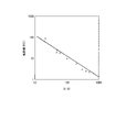
作製した感圧センサーの銀コートナイロン糸を表面と裏面から1本ずつ選んで、デジタルマルチメーター(NF回路設計ブロックDM2561)に接続することにより、感圧センサー装置を得た。選択した2本の糸が導電性布を挟んで直交する位置を加圧した際の、圧力と抵抗値の関係を図5に示す。図5の横軸は加えた圧(g:グラム)を示し、縦軸は抵抗値(kΩ)を示す。図5の結果から明らかなように、本実施例の感圧センサー装置は、20〜1000グラムの圧力変化を高感度且つ高精度に検出可能である。 A pressure-sensitive sensor device was obtained by selecting one silver-coated nylon thread of the produced pressure-sensitive sensor from the front and back surfaces and connecting it to a digital multimeter (NF circuit design block DM2561). FIG. 5 shows the relationship between the pressure and the resistance value when the selected two yarns pressurize at a position perpendicular to each other with the conductive cloth interposed therebetween. The horizontal axis of FIG. 5 shows the applied pressure (g: grams), and the vertical axis shows the resistance value (kΩ). As is clear from the results of FIG. 5, the pressure-sensitive sensor device of this example can detect a pressure change of 20 to 1000 grams with high sensitivity and high accuracy.
以上で説明した各実施形態における各構成及びそれらの組み合わせ等は一例であり、本発明の趣旨を逸脱しない範囲で、構成の付加、省略、置換、およびその他の変更が可能である。また、本発明は各実施形態によって限定されることはなく、請求項(クレーム)の範囲によってのみ限定される。 The configurations and combinations thereof in the embodiments described above are examples, and the addition, omission, replacement, and other modifications of the configurations can be made without departing from the spirit of the present invention. Further, the present invention is not limited by each embodiment, and is limited only by the scope of the claims.
本発明にかかる導電体、導電体の製造方法、感圧センサー、生体電極、感圧センサー装置及び生体信号測定装置は、医療をはじめ、ヘルスプロモーションやインフォメーションテクノロジー、ウエアラブルコンピューターなどの幅広い分野において広く利用可能である。 The electric conductor, the electric conductor manufacturing method, the pressure sensitive sensor, the biological electrode, the pressure sensitive sensor device, and the biological signal measuring device according to the present invention are widely used in a wide range of fields such as medical treatment, health promotion, information technology, and wearable computers. Is possible.
1…導電体(布体)、2…布地(Tシャツ)、3…心電計、4…混合物、5…導電性の糸(銀コートナイロン糸)、6…熱転写シート、7…部材(銀コートナイロン糸)、8…台紙、9…絶縁性布、10…生体電極、10A,10B…導電体、11…指、12…台、20…感圧センサー
DESCRIPTION OF
Claims (2)
前記布体の導電面の両面に当接するように並べて配置された、親水性を有する導電性高分子でコーティングされた繊維からなる複数の導電性の線状部材と、を備え、
前記導電面の表面において略平行に並べて配置された複数の前記部材が、
前記導電面の裏面において略平行に並べて配置された複数の前記部材に対して、略直交するように配置されていることを特徴とする感圧センサー。 A fabric comprising a conductive polymer coated with a conductive polymer having a hydrophilic property and a binder resin coated on a fiber or fabric;
The side by side so as to contact both sides of the conductive surface of the fabric body is arranged, comprising a plurality of conductive linear member made of a fiber coated with a conductive polymer having a hydrophilic and,
A plurality of the members arranged in parallel on the surface of the conductive surface,
A pressure-sensitive sensor, which is arranged so as to be substantially orthogonal to the plurality of members arranged in parallel on the back surface of the conductive surface.
の送受信を行う外部装置と、が備えられたことを特徴とする感圧センサー装置。 A pressure-sensitive sensor device comprising: the pressure-sensitive sensor according to claim 1; and an external device connected to the pressure-sensitive sensor and transmitting / receiving a signal to / from the pressure-sensitive sensor.
Priority Applications (1)
| Application Number | Priority Date | Filing Date | Title |
|---|---|---|---|
| JP2012262468A JP5984645B2 (en) | 2012-11-30 | 2012-11-30 | Pressure sensor and pressure sensor device |
Applications Claiming Priority (1)
| Application Number | Priority Date | Filing Date | Title |
|---|---|---|---|
| JP2012262468A JP5984645B2 (en) | 2012-11-30 | 2012-11-30 | Pressure sensor and pressure sensor device |
Related Child Applications (2)
| Application Number | Title | Priority Date | Filing Date |
|---|---|---|---|
| JP2014195822A Division JP5740038B2 (en) | 2014-09-25 | 2014-09-25 | Biological electrode and biological signal measuring device |
| JP2015198050A Division JP6010203B2 (en) | 2015-10-05 | 2015-10-05 | Conductor, biological electrode, and biological signal measuring device |
Publications (3)
| Publication Number | Publication Date |
|---|---|
| JP2014108134A JP2014108134A (en) | 2014-06-12 |
| JP2014108134A5 JP2014108134A5 (en) | 2014-11-13 |
| JP5984645B2 true JP5984645B2 (en) | 2016-09-06 |
Family
ID=51029151
Family Applications (1)
| Application Number | Title | Priority Date | Filing Date |
|---|---|---|---|
| JP2012262468A Active JP5984645B2 (en) | 2012-11-30 | 2012-11-30 | Pressure sensor and pressure sensor device |
Country Status (1)
| Country | Link |
|---|---|
| JP (1) | JP5984645B2 (en) |
Cited By (3)
| Publication number | Priority date | Publication date | Assignee | Title |
|---|---|---|---|---|
| JP2020008437A (en) * | 2018-07-09 | 2020-01-16 | タカノ株式会社 | Pressure-sensitive sensor and manufacturing method therefor |
| JP2020008439A (en) * | 2018-07-09 | 2020-01-16 | タカノ株式会社 | Pressure-sensitive sensor |
| JP2020008438A (en) * | 2018-07-09 | 2020-01-16 | タカノ株式会社 | Pressure-sensitive sensor and manufacturing method therefor |
Families Citing this family (28)
| Publication number | Priority date | Publication date | Assignee | Title |
|---|---|---|---|---|
| JP6345777B2 (en) * | 2014-06-20 | 2018-06-20 | 国立研究開発法人産業技術総合研究所 | Strain sensor and manufacturing method thereof |
| ES2784656T3 (en) * | 2014-12-08 | 2020-09-29 | Nippon Telegraph & Telephone | Bioelectrode and garment |
| JP6686244B2 (en) * | 2015-03-17 | 2020-04-22 | 国立大学法人東北大学 | Electrode element and electrode production method, and production of measurement system using the electrode |
| JP6039724B2 (en) * | 2015-03-27 | 2016-12-07 | 日本電信電話株式会社 | Biological electrode and biological signal measuring device |
| CN107708542B (en) * | 2015-07-08 | 2021-01-15 | 日本电信电话株式会社 | Living body electrode and wearable electrode |
| JP2017158858A (en) * | 2016-03-10 | 2017-09-14 | グンゼ株式会社 | Clothing including water permeable conductive part |
| CN105233404B (en) * | 2015-11-23 | 2018-05-22 | 浙江力方健康科技有限公司 | A kind of electrode manufacturing method applied to wearable device |
| JP6660542B2 (en) * | 2015-11-30 | 2020-03-11 | タツタ電線株式会社 | Stretchable conductive film for textile |
| WO2017183463A1 (en) * | 2016-04-18 | 2017-10-26 | 東レ株式会社 | Electrically conductive fiber structure, electrode member, and method for manufacturing electrically conductive fiber structure |
| CN109414211B (en) | 2016-07-06 | 2022-05-06 | Nok株式会社 | Bioelectrode and method for producing same |
| JP2018042720A (en) * | 2016-09-14 | 2018-03-22 | グンゼ株式会社 | Bioelectrode |
| JP6960310B2 (en) * | 2016-12-07 | 2021-11-05 | ナガセケムテックス株式会社 | Rough surface conductors and biological sensing devices |
| JP2018102710A (en) * | 2016-12-27 | 2018-07-05 | 株式会社豊田中央研究所 | Electrocardiographic measurement apparatus, method, and program |
| WO2018173749A1 (en) * | 2017-03-21 | 2018-09-27 | グンゼ株式会社 | Conductive composite sheet |
| JP6770493B2 (en) * | 2017-08-10 | 2020-10-14 | 日本電信電話株式会社 | Conductive polymer electrode and method for manufacturing conductive polymer electrode |
| JP7072446B2 (en) * | 2017-11-16 | 2022-05-20 | タツタ電線株式会社 | Bioelectrode and its manufacturing method |
| JP2018099544A (en) * | 2018-03-01 | 2018-06-28 | 学校法人立命館 | Member for forming electrodes and wires, and method for manufacturing the same |
| JP6952645B2 (en) * | 2018-05-22 | 2021-10-20 | ニッタ株式会社 | Pressure sensor |
| JP7377012B2 (en) | 2018-06-14 | 2023-11-09 | 慶一 鳥光 | Conductive materials and electrical elements and sensors equipped with the same |
| JP7377011B2 (en) | 2018-06-14 | 2023-11-09 | 慶一 鳥光 | Force sensing elements and sensors |
| WO2019240241A1 (en) * | 2018-06-14 | 2019-12-19 | 鳥光 慶一 | Electroconductive material and electrical element provided with same, and sensor |
| JP6561371B1 (en) * | 2018-09-11 | 2019-08-21 | エーアイシルク株式会社 | Electrical stimulator |
| US20210345927A1 (en) * | 2018-10-26 | 2021-11-11 | Sumitomo Bakelite Co., Ltd. | Biomedical electrode, biomedical sensor, and biomedical signal measurement system |
| JPWO2020179756A1 (en) | 2019-03-03 | 2020-09-10 | ||
| EP4059428A4 (en) | 2019-11-14 | 2023-06-28 | ASAHI FR R&D Co., Ltd. | Bioelectrode, production method and installation method for bioelectrode |
| KR102283480B1 (en) * | 2019-11-26 | 2021-07-28 | 한국산업기술대학교산학협력단 | Pressure sensing apparatus in artificial leg apparatus possible for user intention decision |
| JP7301089B2 (en) | 2021-04-07 | 2023-06-30 | 住友ベークライト株式会社 | Flexible sheet electrodes, wearable bioelectrodes and biosensors |
| CN114739449B (en) * | 2022-03-11 | 2024-02-02 | 山西省六维人工智能生物医学研究院 | High-air-permeability electronic skin flexible pressure temperature sensor and preparation method thereof |
Family Cites Families (2)
| Publication number | Priority date | Publication date | Assignee | Title |
|---|---|---|---|---|
| JP5586429B2 (en) * | 2010-02-09 | 2014-09-10 | 東海ゴム工業株式会社 | Care system |
| JP5432063B2 (en) * | 2010-05-27 | 2014-03-05 | 東海ゴム工業株式会社 | Bed leaving sensor system |
-
2012
- 2012-11-30 JP JP2012262468A patent/JP5984645B2/en active Active
Cited By (3)
| Publication number | Priority date | Publication date | Assignee | Title |
|---|---|---|---|---|
| JP2020008437A (en) * | 2018-07-09 | 2020-01-16 | タカノ株式会社 | Pressure-sensitive sensor and manufacturing method therefor |
| JP2020008439A (en) * | 2018-07-09 | 2020-01-16 | タカノ株式会社 | Pressure-sensitive sensor |
| JP2020008438A (en) * | 2018-07-09 | 2020-01-16 | タカノ株式会社 | Pressure-sensitive sensor and manufacturing method therefor |
Also Published As
| Publication number | Publication date |
|---|---|
| JP2014108134A (en) | 2014-06-12 |
Similar Documents
| Publication | Publication Date | Title |
|---|---|---|
| JP5984645B2 (en) | Pressure sensor and pressure sensor device | |
| JP5740038B2 (en) | Biological electrode and biological signal measuring device | |
| Yu et al. | Highly stretchable, weavable, and washable piezoresistive microfiber sensors | |
| US8925393B2 (en) | Device intended for measuring pressure from a flexible, foldable, and/or extendable object made of a textile material and comprising a measurement device | |
| KR101558407B1 (en) | Fabric for acquiring physiological signals | |
| JP5986008B2 (en) | Method for manufacturing conductive fabric and method for manufacturing biological signal measuring apparatus | |
| JP2014228507A (en) | Extension sensor and measuring apparatus | |
| Jang et al. | Carbon-based, ultraelastic, hierarchically coated fiber strain sensors with crack-controllable beads | |
| US20140150573A1 (en) | Device for Measuring Pressure from a Flexible, Pliable, and/or Extensible Object Made from a Textile Material Comprising a Measurement Device | |
| CN108085988A (en) | The preparation method of condenser type stress sensing intelligent fabric | |
| JP6010203B2 (en) | Conductor, biological electrode, and biological signal measuring device | |
| CN102770742A (en) | Flexible pressure sensor and flexible pressure sensing array | |
| JP6039724B2 (en) | Biological electrode and biological signal measuring device | |
| CN210014750U (en) | Capacitive elastic strain sensor and wearable product | |
| CN110657741A (en) | Capacitive elastic strain sensor, and preparation method and application thereof | |
| US11740143B2 (en) | Flexible pressure sensor array and method for fabricating the same | |
| Fan et al. | Highly conductive, stretchable, and breathable epidermal electrode based on hierarchically interactive nano-network | |
| CN111855036A (en) | Ultra-wide range flexible sensor, preparation method thereof and distributed pressure monitoring system | |
| CN106725418A (en) | A kind of flexible electrode based on carbonized fabric | |
| TW201942205A (en) | Conductive polymer conductor, and method for manufacturing same | |
| Yan et al. | Highly breathable, surface-hydrophobic and wet-adhesive silk based epidermal electrode for long-term electrophysiological monitoring | |
| JP2015077321A (en) | Biological signal acquisition electrode, and biological signal acquisition device and method | |
| Fan et al. | Highly Sensitive Fabric Sensors Based on Scale-like Wool Fiber for Multifunctional Health Monitoring | |
| CN113340481A (en) | Pressure sensor and preparation method thereof | |
| KR20210024798A (en) | Manufacture Of Conductive Nonwoven Fabric Using Dyeing Process |
Legal Events
| Date | Code | Title | Description |
|---|---|---|---|
| A521 | Written amendment |
Free format text: JAPANESE INTERMEDIATE CODE: A523 Effective date: 20140925 |
|
| A621 | Written request for application examination |
Free format text: JAPANESE INTERMEDIATE CODE: A621 Effective date: 20140925 |
|
| A977 | Report on retrieval |
Free format text: JAPANESE INTERMEDIATE CODE: A971007 Effective date: 20150619 |
|
| A131 | Notification of reasons for refusal |
Free format text: JAPANESE INTERMEDIATE CODE: A131 Effective date: 20150804 |
|
| A521 | Written amendment |
Free format text: JAPANESE INTERMEDIATE CODE: A523 Effective date: 20151005 |
|
| A02 | Decision of refusal |
Free format text: JAPANESE INTERMEDIATE CODE: A02 Effective date: 20160315 |
|
| A521 | Written amendment |
Free format text: JAPANESE INTERMEDIATE CODE: A523 Effective date: 20160613 |
|
| A911 | Transfer to examiner for re-examination before appeal (zenchi) |
Free format text: JAPANESE INTERMEDIATE CODE: A911 Effective date: 20160620 |
|
| TRDD | Decision of grant or rejection written | ||
| A01 | Written decision to grant a patent or to grant a registration (utility model) |
Free format text: JAPANESE INTERMEDIATE CODE: A01 Effective date: 20160728 |
|
| A61 | First payment of annual fees (during grant procedure) |
Free format text: JAPANESE INTERMEDIATE CODE: A61 Effective date: 20160802 |
|
| R150 | Certificate of patent or registration of utility model |
Ref document number: 5984645 Country of ref document: JP Free format text: JAPANESE INTERMEDIATE CODE: R150 |