EP3286812B1 - Intelligent power strip with management of bistable relays to reduce current in-rush - Google Patents
Intelligent power strip with management of bistable relays to reduce current in-rush Download PDFInfo
- Publication number
- EP3286812B1 EP3286812B1 EP16718806.9A EP16718806A EP3286812B1 EP 3286812 B1 EP3286812 B1 EP 3286812B1 EP 16718806 A EP16718806 A EP 16718806A EP 3286812 B1 EP3286812 B1 EP 3286812B1
- Authority
- EP
- European Patent Office
- Prior art keywords
- power
- brc
- bistable
- pdu
- bistable relays
- Prior art date
- Legal status (The legal status is an assumption and is not a legal conclusion. Google has not performed a legal analysis and makes no representation as to the accuracy of the status listed.)
- Active
Links
- 238000012544 monitoring process Methods 0.000 claims description 12
- 238000001514 detection method Methods 0.000 claims description 8
- 238000000034 method Methods 0.000 claims description 6
- 230000007704 transition Effects 0.000 claims description 5
- 230000004044 response Effects 0.000 claims description 3
- 238000011144 upstream manufacturing Methods 0.000 description 6
- 230000006854 communication Effects 0.000 description 5
- 238000004891 communication Methods 0.000 description 5
- 230000008859 change Effects 0.000 description 4
- 238000005259 measurement Methods 0.000 description 4
- 230000003287 optical effect Effects 0.000 description 4
- 230000002159 abnormal effect Effects 0.000 description 3
- 230000006399 behavior Effects 0.000 description 3
- 238000010586 diagram Methods 0.000 description 3
- 230000006870 function Effects 0.000 description 3
- 230000007175 bidirectional communication Effects 0.000 description 2
- 238000013461 design Methods 0.000 description 2
- 238000004519 manufacturing process Methods 0.000 description 2
- 230000001360 synchronised effect Effects 0.000 description 2
- 101100024083 Saccharomyces cerevisiae (strain ATCC 204508 / S288c) MPH2 gene Proteins 0.000 description 1
- 230000009471 action Effects 0.000 description 1
- 238000004458 analytical method Methods 0.000 description 1
- 239000003990 capacitor Substances 0.000 description 1
- 238000006243 chemical reaction Methods 0.000 description 1
- 230000008878 coupling Effects 0.000 description 1
- 238000010168 coupling process Methods 0.000 description 1
- 238000005859 coupling reaction Methods 0.000 description 1
- 230000001186 cumulative effect Effects 0.000 description 1
- 230000003111 delayed effect Effects 0.000 description 1
- 230000009977 dual effect Effects 0.000 description 1
- 238000005516 engineering process Methods 0.000 description 1
- 238000001914 filtration Methods 0.000 description 1
- 238000009434 installation Methods 0.000 description 1
- 238000012986 modification Methods 0.000 description 1
- 230000004048 modification Effects 0.000 description 1
- 230000002085 persistent effect Effects 0.000 description 1
- 230000008569 process Effects 0.000 description 1
- 238000012545 processing Methods 0.000 description 1
- 238000012163 sequencing technique Methods 0.000 description 1
- 230000035939 shock Effects 0.000 description 1
- 239000007787 solid Substances 0.000 description 1
- 239000013589 supplement Substances 0.000 description 1
- 238000012360 testing method Methods 0.000 description 1
Images


Classifications
-
- H—ELECTRICITY
- H02—GENERATION; CONVERSION OR DISTRIBUTION OF ELECTRIC POWER
- H02H—EMERGENCY PROTECTIVE CIRCUIT ARRANGEMENTS
- H02H1/00—Details of emergency protective circuit arrangements
- H02H1/04—Arrangements for preventing response to transient abnormal conditions, e.g. to lightning or to short duration over voltage or oscillations; Damping the influence of dc component by short circuits in ac networks
- H02H1/043—Arrangements for preventing response to transient abnormal conditions, e.g. to lightning or to short duration over voltage or oscillations; Damping the influence of dc component by short circuits in ac networks to inrush currents
-
- H—ELECTRICITY
- H02—GENERATION; CONVERSION OR DISTRIBUTION OF ELECTRIC POWER
- H02H—EMERGENCY PROTECTIVE CIRCUIT ARRANGEMENTS
- H02H9/00—Emergency protective circuit arrangements for limiting excess current or voltage without disconnection
- H02H9/02—Emergency protective circuit arrangements for limiting excess current or voltage without disconnection responsive to excess current
-
- H—ELECTRICITY
- H01—ELECTRIC ELEMENTS
- H01R—ELECTRICALLY-CONDUCTIVE CONNECTIONS; STRUCTURAL ASSOCIATIONS OF A PLURALITY OF MUTUALLY-INSULATED ELECTRICAL CONNECTING ELEMENTS; COUPLING DEVICES; CURRENT COLLECTORS
- H01R13/00—Details of coupling devices of the kinds covered by groups H01R12/70 or H01R24/00 - H01R33/00
- H01R13/66—Structural association with built-in electrical component
- H01R13/70—Structural association with built-in electrical component with built-in switch
-
- H—ELECTRICITY
- H02—GENERATION; CONVERSION OR DISTRIBUTION OF ELECTRIC POWER
- H02H—EMERGENCY PROTECTIVE CIRCUIT ARRANGEMENTS
- H02H3/00—Emergency protective circuit arrangements for automatic disconnection directly responsive to an undesired change from normal electric working condition with or without subsequent reconnection ; integrated protection
- H02H3/02—Details
- H02H3/06—Details with automatic reconnection
-
- H—ELECTRICITY
- H02—GENERATION; CONVERSION OR DISTRIBUTION OF ELECTRIC POWER
- H02H—EMERGENCY PROTECTIVE CIRCUIT ARRANGEMENTS
- H02H3/00—Emergency protective circuit arrangements for automatic disconnection directly responsive to an undesired change from normal electric working condition with or without subsequent reconnection ; integrated protection
- H02H3/08—Emergency protective circuit arrangements for automatic disconnection directly responsive to an undesired change from normal electric working condition with or without subsequent reconnection ; integrated protection responsive to excess current
-
- H—ELECTRICITY
- H02—GENERATION; CONVERSION OR DISTRIBUTION OF ELECTRIC POWER
- H02H—EMERGENCY PROTECTIVE CIRCUIT ARRANGEMENTS
- H02H3/00—Emergency protective circuit arrangements for automatic disconnection directly responsive to an undesired change from normal electric working condition with or without subsequent reconnection ; integrated protection
- H02H3/46—Emergency protective circuit arrangements for automatic disconnection directly responsive to an undesired change from normal electric working condition with or without subsequent reconnection ; integrated protection responsive to frequency deviations
-
- H—ELECTRICITY
- H02—GENERATION; CONVERSION OR DISTRIBUTION OF ELECTRIC POWER
- H02J—CIRCUIT ARRANGEMENTS OR SYSTEMS FOR SUPPLYING OR DISTRIBUTING ELECTRIC POWER; SYSTEMS FOR STORING ELECTRIC ENERGY
- H02J3/00—Circuit arrangements for ac mains or ac distribution networks
-
- H—ELECTRICITY
- H04—ELECTRIC COMMUNICATION TECHNIQUE
- H04Q—SELECTING
- H04Q9/00—Arrangements in telecontrol or telemetry systems for selectively calling a substation from a main station, in which substation desired apparatus is selected for applying a control signal thereto or for obtaining measured values therefrom
-
- H—ELECTRICITY
- H05—ELECTRIC TECHNIQUES NOT OTHERWISE PROVIDED FOR
- H05K—PRINTED CIRCUITS; CASINGS OR CONSTRUCTIONAL DETAILS OF ELECTRIC APPARATUS; MANUFACTURE OF ASSEMBLAGES OF ELECTRICAL COMPONENTS
- H05K7/00—Constructional details common to different types of electric apparatus
- H05K7/14—Mounting supporting structure in casing or on frame or rack
- H05K7/1485—Servers; Data center rooms, e.g. 19-inch computer racks
- H05K7/1488—Cabinets therefor, e.g. chassis or racks or mechanical interfaces between blades and support structures
- H05K7/1492—Cabinets therefor, e.g. chassis or racks or mechanical interfaces between blades and support structures having electrical distribution arrangements, e.g. power supply or data communications
-
- H—ELECTRICITY
- H04—ELECTRIC COMMUNICATION TECHNIQUE
- H04Q—SELECTING
- H04Q2209/00—Arrangements in telecontrol or telemetry systems
- H04Q2209/60—Arrangements in telecontrol or telemetry systems for transmitting utility meters data, i.e. transmission of data from the reader of the utility meter
Description
- The present disclosure relates to intelligent power strips with bistable relays, and more particularly to an intelligent power strip which is able to control a plurality of bistable relays in a manner to limit in-rush current as external devices being powered by the intelligent power strip are turned on.
- This section provides background information related to the present disclosure which is not necessarily prior art.
- Certain models of intelligent power strips use power relays, typically rated less than 250V 20Arms, to switch a line of a receptacle for the main purpose of rebooting a connected load device, e.g., server. Depending upon the load device's internal power supply design, substantial in-rush currents may occur while its input bulk capacitors charge up the moment the relay contacts are closed. This brief, but large current surge, can permanently damage the relay contacts, i.e., weld them close, so they are no longer operative. It can also cause the upstream circuit protection device, typically a circuit breaker, to trip. Some relay manufacturers offer more expensive devices that can handle momentary current surges up to four times their design rating. To further supplement the protection of the relay contacts, the in-rush currents can be mitigated by coordinated timing of relay closure according to the voltage zero-crossing of line frequency.
-
US 2014/218008 discloses a power distribution unit comprising at least one power receptacle configured to enable attachment of an alternating current power cord of an external device to the power receptacle.$ - A number of power strips commonly referred to as Rack PDUs, have switching capabilities associated with all receptacles. PDU stands for power distribution unit and a Rack PDU is used in racks that hold electronic equipment such as servers. The primary reason for the switching capabilities has been two-fold: (a) To be able to remotely recycle power to a connected equipment that is hung up; and (b) to be able to sequentially start up all connected equipment to ensure that upstream breakers do not trip due to all connected loads drawing high in-rush currents concurrently. Typical IT (information technology) loads, for example servers, can draw as much as 5 times their normal current at the time of startup. The above capabilities have typically been addressed in the past through the use of solid state relays at each receptacle.
- Bistable relays are increasingly being used in Rack PDU's as they are more energy efficient since their coils do not need to remain energized to maintain the state of their contacts. In such a bistable relay, the coil is pulsed to change the state of the contacts from open to closed and vice-versa. The contacts will then remain in their existing state until the coil is pulsed again. In contrast, in a typical normally open relay, when it is desired to close the contacts of the relay, the coil of the relay must be energized and kept energized to keep the contacts closed. When the coil of the typical normally open relay is de-energized, the relay contacts revert to their normally open state. Similarly, in a typical normally closed relay, when it is desired to open the contacts of the relay, the coil of the relay must be energized and kept energized to keep the contacts open. When the coil of typical normally closed relay is de-energized, the relay contacts revert to their normally closed state. In Rack PDU's having bistable relays, the bistable relays that are closed when there is a loss of power will remain closed. When power is restored, the cumulative in-rush current through the closed bistable relays may cause the upstream circuit protection device, typically a circuit breaker, to trip.
- In one aspect the present invention relates to a power distribution unit (PDU) as defined by
claim 1. - In another aspect the present disclosure not belonging to the invention, relates to a power distribution unit (PDU) which may comprise at least one power receptacle configured to enable attachment of an alternating current (AC) power cord of an external device to the power receptacle. A branch receptacle controller (BRC) may be included which has a plurality of bistable relays and which is associated with the at least one power receptacle, for supplying AC power to the at least one power receptacle from an external AC power source. Each of the bistable relays may have contacts able to be set to an open position and to a closed position. The BRC may further be configured for monitoring a frequency of a line voltage from the external AC power source, and to use the monitored frequency to detect when a loss of AC power occurs, and to toggle any one or more of the bistable relays which is a closed position to an open position upon the detection of an AC power loss condition. The BRC may further detect a loss of AC power condition by monitoring the frequency of the line voltage and determining, from information relating to a zero crossing of the monitored frequency, that an AC power loss condition has occurred. A rack power distribution unit controller (RPDUC) may also be included which is configured to communicate with the BRC and to control the bistable relays such that the relays that were previously in a closed position prior to the AC power loss condition are all sequentially commanded to again be closed after the AC Power is restored, in a manner that limits an in-rush of current to the PDU.
- In still another aspect the present invention relates to a method for monitoring and controlling an application of AC power to a plurality of data center devices. The method may comprise providing at least one AC power receptacle forming a power attachment point for an alternating current (AC) power cord of an independent data center device. The method may also comprise using a branch receptacle controller (BRC) having at least one bistable relay associated with the power receptacle for supplying AC power to the AC power receptacle from an external AC power source, the bistable relay having contacts which are able to be set to an open position and to a closed position. The BRC may be used to monitor a parameter associated with a line voltage of the external AC power source. The monitored parameter may be used to detect when a loss of AC power is about to occur. In response to a detected imminent loss of AC power, the BRC may be used to toggle the bistable relay, if the bistable relay is currently in a closed position immediately before power is lost, to an open position, before power to the BRC is lost. A rack power distribution unit controller (RPDUC) may be used which is configured to communicate with the BRC and to monitor a state of the bistable relay, and to command the BRC to close the bistable relay after AC power is restored.
- The drawings described herein are for illustrative purposes only of selected embodiments and not all possible implementations, and are not intended to limit the scope of the present disclosure.
-
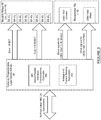
Fig. 1 is a block diagram of one embodiment of a PDU in accordance with the present disclosure for monitoring and controlling AC power applied to each one of a plurality of AC power receptacles of the PDU; -
Fig. 2 is a high level block diagram of the RPDUC in accordance with one embodiment of the present disclosure; -
Fig. 3 is a block diagram of one embodiment of the CPLD used in the BRC; and -
Fig. 4 illustrates eight (8) bistable relays arranged in two sub banks (i.e., sub bank A and sub bank B). - Corresponding reference designations indicate corresponding parts throughout the several views of the drawings.
- Example embodiments will now be described more fully with reference to the accompanying drawings.
- In accordance with an aspect of the present disclosure, bistable relays of an intelligent power distribution strip are managed so that in-rush current is minimized upon restoration of power after a power loss. Since the relays are bistable relays, their last state is persistent regardless of power condition. Upon loss of power, the bistable relays are controlled so that all closed bistable relays are automatically opened. Loss of power can be due to loss of source AC power from an upstream power utility, failure of an uninterruptible power supply ("UPS") upstream of the intelligent power distribution strip that provides power to the intelligent power distribution strip, or a circuit breaker tripping due to overcurrent conditions. Upon the next power up cycle, the bistable relays that are to be closed are closed sequentially with each one of such bistable relays being closed per every N line cycles to minimize overall in-rush current and prevent the upstream circuit breaker from tripping. The line frequency is monitored and detection of loss of line frequency indicates imminent power loss resulting in the bistable relays being opened. Each bistable relay that is to be closed during the next power up cycle is closed during the power up cycle at a minimum voltage (zero voltage crossing) point of line frequency to minimize contact arcing and in-rush current through its relay contacts. The bistable relays may be opened at a minimum current (zero current crossing) point of line frequency to minimize contact arcing.
- With reference to
Fig. 1 of the drawings, an illustrative Rack PDU in accordance with the present disclosure is described. In the following description,MPH2 10 represents the Rack PDU, and will hereinafter simply be referred to as "MPH 10". A RPC2000 12 (hereinafter simply "RPC 12") in this example may be a hot-swappable web card which is installed in the MPH 10. TheRPC 12 may include amicrocontroller 14 and preferably also a non-volatile (NV)memory 16. TheRPC 12 may also include a plurality of ports including, but not limited to, aLAN Ethernet port 18, an Expansion/Management port 20, aport 22 for coupling to a display module (e.g., "BDM" or "Basic Display Module" available from the assignee of the present disclosure), one or more 1-wire sensor ports 24, an RD-232port 26 and aUSB port 28. The MPH 10 further includes a Rack PDU Controller (RPDUC) 30 having amicrocontroller 32 and anon-volatile memory 34, and one or more branch receptacle controllers (BRC) 36. EachBRC 36 may have a complex programmable logic device (CPLD) 38 having a voltage andcurrent sensing subsystem 38a which senses of a loss of AC input power, a plurality ofbistable relays 40, and an open circuit breaker (OCB)detection subsystem 42 which senses for an open circuit breaker condition. The RPDUC 30 is in bidirectional communication with each of the BRCs 36 via abus 44. TheRPC 12 is in bidirectional communication with theRPDUC 30 via abus 46. Areset switch 48, which is easily accessible by a user via a faceplate of theMPH 10, is provided for enabling the user to initiate a hard reset to theBRCs 36 of the system 10A. -
Fig. 1 also shows a plurality of branch circuit breakers (CB) 50. By "branch" circuit breaker it is meant that each of theCBs 50 are uniquely associated with onespecific BRC 36. TheOCB detection subsystem 42 monitors theCBs 50 to detect when any one or more have been tripped to an open condition. And as explained above, eachBRC 36 includes a plurality ofbistable relays 40, which in one specific embodiment comprise eight (8) bistable relays. However, it will be appreciated that a greater or lesser number ofbistable relays 40 could be provided per branch. Mechanical bistable relays have coils and mechanical contacts. They can be single coil or dual coil relays. Also, more than oneCB 50 may exist for eachBRC 36. For example, eachBRC 36 can have its bistable relays arranged in two sub banks, with aseparate CB 50 associated with each sub-bank. As used herein, each sub-bank of aBRC 36 is a branch of the BRC. -
Fig. 1 also shows a plurality ofAC power receptacles 10a each having a first associated optical element 10a1 and a second optical element 10a2. Optical elements 10a1 may each be an LED having a first color, for example green, that indicates a status of the specificbistable relay 40 associated with itsspecific AC receptacle 10a. The second group of optical elements 10a2 may also be, for example, LEDs having a different color, for example red, for providing additional information to the user. Each one of the green LEDs 10a1 may indicate, for example, that thebistable relay 40 associated with thatspecific AC receptacle 10a is closed, and an extinguished green LED 10a1 would therefore indicate that the associated bistable relay is open. Input power to theMPH 10 may be from an uninterruptible power supply (UPS) or from any other AC power source. - The
RPDUC 30 is shown in greater detail inFig. 2 . TheRPDUC 30 includes avoltage sensing subsystem 52 and acurrent sensing subsystem 54. Thesubsystems RPC 12 viabus 44. As noted above, the voltage andcurrent sensing subsystem 38a of eachBRC 36 also monitors for a loss of AC input power, so in this regard there is redundancy of this feature in theRPDUC 30 and theBRCs 36. Thecurrent sensing subsystem 54 of theRPDUC 30 receives an input current signal from each of the branch BRCs (collectively labeled for simplicity inFig. 2 with number 36) which it uses to perform its current sensing function. Eachbranch BRC 36 also includes a plurality of current transformers (CTs) 56 for independently measuring a current being drawn by theAC receptacles 10a associated with each branch of bistable relays 40. The signals from eachbranch CT 56 are input to thecurrent sensing subsystem 54 for analysis. - The
RPC 12 shown inFig. 1 manages, monitors and reports information aboutMPH 10 energy metering and power distribution status obtained from theRPDUC 30 to networked software clients. TheRPDUC 30 provides support for the energy metering measurements and calculations, control management, and communications interfaces to theRPC 12, as described above. TheRPDUC 30 communicates with eachBRC 36 and, except upon power loss, controls thebistable relays 40 of each BRC by sending command messages to each BRC to independently control each one of its associated bistable relays 40. - The
BRC 36, and more particularly itsCPLD 38, directly controls its bistable relays 40. TheBRC 36 also senses individual LED receptacle operational status, and loss of an AC input power signal via line frequency monitoring performed by the voltage andcurrent detection subsystem 38a, as well as using theOCB subsystem 42 to detect for an open circuit breaker condition. The bistable relays 40 of eachBRC 36 in this example require a nominal 16 msec pulse to their coils to change states, that is, to open or close their contacts. A reference herein to a bistable relay being "open" means that its contacts are open and power is off or interrupted at thereceptacle 10a to which the bistable relay switches power. As used herein, "power up", "power down", "power failure", and "power cycle" refer to specific conditions of input AC line voltage, which is the AC power provided to thereceptacles 10a through thebistable relays 40 of eachBRC 36. The term "Configured state", when used in connection with thebistable relays 40, means the state that a given bistable relay is configured to be in (i.e., open or closed) when power is on. - The
RPC 12 commands theRPDUC 14 via a SMBus (I2C) communication bus,bus 46 inFig. 1 in this example, which in turn, commands theBRC 36 via a SPI communication bus, which isbus 44 in this example, to configure the relay state of eachbistable relay 40. TheRPDUC 30 is capable of autonomous behavior withoutRPC 12 commands. The one ormore BRCs 36 are each capable of autonomous behavior withoutRPDUC 30 commands. - Referring to
Fig. 3 , theCPLD 38 of one of theBRCs 36 is shown in greater detail. In this example eight bistable relays 401-408 are shown, but it will be appreciated that theMPH 10 may control a greater or lesser number of bistable relays 40. TheCPLD 38 includes a serial-parallel interface ("SPI")controller 38b that manages communications with other subsystems of the CPLD. TheCPLD 38 includes suitable logic for generating signals to independently command thebistable relays 40 to each assume a first state ("SET" signals) or a second state ("RESET" signals). TheCPLD 38 also includes logic for controlling the green LEDs 10a1 and the red LEDs 10a2. The CPLD may control the green LEDs 10a1 so that the green LEDs 10a1 flash at a first rate when a given bank ofbistable relays 40 is drawing a current which is close to an upper predetermined current limit. TheCPLD 38 may control the green LEDs 10a1 so that the green LEDs 10a1 flash at a second rate different from the first rate (e.g., faster rate) when an overcurrent condition arises (i.e., a given bank ofbistable relays 40 is drawing more current than allowed). TheCPLD 38 may control the red LEDs 10a2 so that all of the red LEDs 10a2 stay illuminated continuously if an over-current condition arises where a given bank ofbistable relays 40 is drawing more current than allowed. The red LEDs 10a2 may also be controlled to flash or pulse if an open circuit board condition arises. - In the
BRCs 36, the voltage andcurrent sensing subsystem 38a of eachCPLD 38 monitor loss of line frequency on load sides of therespective CB 50 for each of theBRCs 36. EachBRC 36 allows for two sub-banks of power distribution and the AC power feed can be either same or differently phased. Each sub-bank ofbistable relays 40 may optionally have itsown CPLD 38 andOCB subsystem 42.Fig. 4 illustrates eight (8) bistable relays 401-408 arranged in two sub banks (i.e., sub bank A and sub bank B). - Each of the one or more BRCs 36 infers imminent power loss by detecting a loss of line frequency of the AC line signal from the AC power source. Each
BRC 36 monitors the line frequency and sets true loss of line frequency status after a short period during which less than the expected number of detected voltage zero crossing transitions of the AC line signal has occurred. A true loss of line frequency is defined to be when less than three (3) zero voltage transitions or zero crossings occur over a 32.768ms interval, satisfying both 50/60Hz operation. The zero crossing detection hardware of theBRC 36 has built-in hysteresis and digitizes the line frequency. The digitized line frequency is provided to theBRC 36 that uses digital filtering for reliable triggering. In this regard, theBRC 36 counts zero-crossing voltage transitions to make this determination. The number of transitions allows for a single worst case ½ cycle delay for zero crossing. - The detection period for detecting loss of line frequency must be small so that the relay coil voltage of each
bistable relay 40, derived from thepower supply 30a which is powering the entire system 10 (i.e., theRPDUC 30, theBRC 36 and the RPC 12), is maintained sufficiently long enough (typically about 16ms) for theBRC 36 to pulse thebistable relays 40 that need to be opened into the open state. At a worst case fully loaded condition, i.e., powered at 70Vac andRPC 12 fully operational, there is approximately 64ms of power supply hold time. - The
RPDUC 30 has a similar capability to monitor the loss of line frequency on a line side of theCB 50, as indicated by dashedline 47 inFig. 1 . For monitoring redundancy, its loss of line frequency status may be commanded or indicated by dedicated signals via theSPI communication bus 44 going to eachBRC 36, so that eachBRC 36 may monitor and compare its own loss of line status, to the status being reported by theRPDUC 30, before any action is taken by theBRC 36. Also, theRPDUC 14 may assert a dedicated signal going to theRPC 12 to cause it to enter a low power operating mode in order to extend the power supply hold time. - The
BRC 36CPLD 38 doesn't distinguish between power loss due to loss of line power or due toCB 50 open conditions. Therefore, upon power loss, theBRC 36 controls all thebistable relays 40 in the affected sub-bank so that their contacts are switched to (or left in) the open condition. That is, upon power loss, theBRC 36 opens thebistable relays 40 that are closed and leaves open the bistable relays that are open. - A commanded
receptacle 10a state overrides autonomous power-up state behavior. That is, if during a power-up cycle a power-up delay for areceptacle 10a is pending due to the sequencing of closing thebistable relays 40 that are to be closed, a separate command to power on a receptacle results in immediate processing closure of thebistable relay 40 for that receptacle. - At initial system startup, all
CBs 50 are manually tripped by a user to the open state before power is applied. This results in theRPDUC 30, upon power-up, autonomously commanding the BRCs 36 to control all thebistable relays 40 to be open immediately to mitigate in-rush currents. Afterwards, theRPDUC 30 queries eachBRC 36 to confirm that all of itsbistable relays 40 are open and, if they are, alerts a user that theCBs 50 for thatBRC 36 may then be closed. The LED 10a1 associated with eachreceptacle 10a is on (illuminated) when thebistable relay 40 for that receptacle is then closed, and is off when the bistable relay for that receptacle is open. Although thebistable relays 40 would typically be set to the default "open" position at manufacturing time, the occurrence of excessive shock or vibration during transportation and/or installation may cause a change in state. - If for the
same BRC 36 oneCB 50 is detected to be closed at line power loss (true loss of line frequency), allbistable relays 40 are set to their configuredreceptacle 10a power up state by theRPDUC 30. That is, thebistable relays 40 that are in a closed state at line power loss are set to be re-closed upon power up, and the bistable relays that are in an open state are set to remain open upon power up. - If for the
same BRC 36, bothCBs 50 are detected open at line power loss (true loss of line frequency), all thebistable relays 40 are controlled by theRPDUC 30 so that all of thesebistable relays 40 remain open at power up until theCBs 50 are closed. Upon theCBs 50 being closed, theRPDUC 30 proceeds as discussed above during initial system start up. Then upon confirming that all thebistable relays 40 of aBRC 36 are open, theRPDUC 30 then proceeds to command the BRC to close thebistable relays 40 that are to be closed, which the RPDUC may do sequentially as discussed below. - If the power supply of the
RPDUC 30 fails, the RPDUC and theBRCs 36 no longer operate; however, thebistable relays 40 remain in their last configured states, even during subsequent power cycle(s). In this aspect, the power supply of theRPDUC 30 provides power to theBRC 36. - The current
bistable relay 40 states are immediately updated in the volatile register memory (not shown) of theBRC 36 when configured by theRPDUC 30 and/or when autonomously changed by theBRC 36, and the volatile register memory can be read by theRPDUC 30 from eachBRC 36. TheRPDUC 30 then updates the states for thosebistable relays 22 stored innon-volatile memory 34 of the RPDUC. - Except in the event of a power loss where all the closed bistable relays of each affected sub bank of each
affected BRC 36 are opened, only a single bistable relay state per branch of a BRC is permitted to change per N line cycles to mitigate in-rush currents and prevent theCB 50 associated with that particular branch from unexpectedly opening or tripping. For example, during a power up cycle of an affected branch of aBRC 36, theRPDUC 30 determines whichbistable relays 40 of that affected branch are to be closed. It then sequentially sends commands to theBRC 36 to close thosebistable relays 40, one command for a different bistable relay every N line cycles. That is, theRPDUC 30 sends the BRC 36 a command to close one of thebistable relays 40 that are to be closed every N line cycles. This results in one suchbistable relay 40 being closed every N line cycles. It should be understood that thenon-volatile memory 34 of theRPDUC 30 is used by the RPDUC to store the real time configured states of all thebistable relays 40 of all theBRCs 36. TheRPDUC 30 then determines which bistable relays of an affected branch of an affectedBRC 36 are to be closed during a power-up cycle based on the stored configured states. - The
RPDUC 30 may have an all-digital phase-locked loop implemented in firmware. TheRPDUC 30 may operate to lock onto the line frequency and precisely coordinate analog-to-digital conversion processes for voltage and current measurements, and to send commands to theBRCs 36 in a deterministic fashion prior to voltage zero-crossing of line frequency. TheRPDUC 30 may also command eachBRC 36 to close its associatedbistable relays 40 according to a synchronized timing to a minimum voltage, which will be at the zero cross of line frequency, to mitigate in-rush current. TheRPDUC 30 may synchronize to both line-neutral and line-line voltages. TheRPDUC 30 commands eachBRC 36 to open its associatedbistable relays 40 according to synchronized timing to minimum current zero crossing of line frequency to minimize contact arcing. - The open and close timings of the
bistable relays 40 may be measured during manufacturing functional testing and saved to non-volatile memory, such as thenon-volatile memory 34 of theRPDUC 30. It should be understood that theBRC 36 may have non-volatile memory as well, and that these timings could alternatively or additionally be saved to the non-volatile memory of the BRC and retrieved by theRPDUC 30 as needed. It will also be understood that thebistable relays 40 have an inherent delayed response until release/open states are achieved because of the coils' operate/release times. These timing values are used by theRPDUC 30 to compensate the command execution timing to better synchronize the actual open/close states according to arrival of the voltage and current zero crossing states. For example, if a particularbistable relay 40 was measured to have a 9 msec close time, when theRPDUC 30 is sending a command to theBRC 36 having thatbistable relay 40, to cause it to close, the RPDUC does so 9 msec before the next zero voltage line crossing point. - The
RPDUC 30 may also compensate for relay contact bounce by commanding the closure state ~1 msec earlier so that a typical 1-2 msec contact bounce occurs around line voltage zero-crossing point. In the foregoing example of thebistable relay 40 having a 9 msec closure time, theRPDUC 14 then sends the command to theBRC 36 to close thebistable relay 10 msec in advance of the next line voltage zero-crossing point. - The
RPC 12 may also report an abnormal operating condition when abistable relay 40 is commanded to be opened but current is still measured flowing through it. As shown inFig. 2 , eachreceptacle 10a has one of thecurrent transformers 56 associated with it that is used to measure current being drawn by the receptacle. This abnormal condition may result from failed or stuck closed relay contacts. TheBRC 36 communicates the currents being measured by itscurrent transformers 56 to theRPDUC 30 which then determines whether such an abnormal operating condition exists. If one does exist, theRPDUC 30 communicates this to theRPC 12. - As shown in the drawings, each of the
RPC 12,RPDUC 30 and theBRC 36 include theCPLD 38, themicrocontroller 32 and themicrocontroller 14, respectively, which each include appropriate logic for implementing the above described logic functions. It should be understood that other types of devices can be used such as a digital processor (DSP), microprocessor, microcontroller, Field Programmable Gate Array (FPGA), or application specific integrated circuit (ASIC). When it is stated thatRPC 12,RPDUC 30 orBRC 36 have logic for a function, it should be understood that such logic can include hardware, software, or a combination thereof, including the logic implemented in the CPLD. - The foregoing description of the embodiments has been provided for purposes of illustration and description. It is not intended to be exhaustive or to limit the disclosure. Individual elements or features of a particular embodiment are generally not limited to that particular embodiment, but, where applicable, are interchangeable and can be used in a selected embodiment, even if not specifically shown or described. The same may also be varied in many ways. Such variations are not to be regarded as a departure from the disclosure, and all such modifications are intended to be included within the scope of the disclosure The invention is defined by the appended claims.
Claims (13)
- A power distribution unit, PDU, comprising:at least one pair of power receptacles (10a) configured to enable attachment of a pair of alternating current, abbreviation AC, power cords of a pair of external devices to the PDU;a branch receptacle controller, BRC, having at least one pair of bistable relays (40) associated with the at least one pair of power receptacle for supplying AC power to the at least one pair of power receptacles from an external AC power source, each bistable relay of the at least one pair of bistable relays having contacts able to be set to an open position and to a closed position;the BRC further configured for monitoring a parameter of a line voltage from the external AC power source, and to use the monitored parameter to detect when a loss of AC power is imminent, and to toggle each said bistable relay, if said bistable relay is in a closed position immediately before power is lost, to an open position before an AC power loss condition arises; anda rack power distribution unit controller, RPDUC, configured to communicate with the BRC and to monitor a state of each said bistable relay of the at least one pair of bistable relays, and to command the BRC to selectively close each one of the bistable relays , that were in the closed position immediately before power was lost, after AC power is restored.
- The PDU of claim 1, further comprising a rack programmable controller, RPC, configured to monitor energy metering and power distribution status information concerning the PDU, and to communicate the information to at least one external subsystem to provide.
- The PDU of claim 1, wherein when both the at least one pair of bistable relays were opened after a loss of AC power, the RPDUC operates to sequentially close bistable relays of the at least one pair of bistable relays to limit an in-rush of current to the PDU.
- The PDU of claim 1, wherein the BRC includes an open circuit breaker detection subsystem for detecting when a circuit breaker associated with either one of the bistable relays has opened.
- The PDU of claim 1, wherein the monitoring of the parameter of the line voltage includes monitoring a frequency of the line voltage by the BRC, and using the parameter to detect the loss of AC power by monitoring a zero crossing of a line voltage of the AC power being supplied to the PDU.
- The PDU of claim 5, wherein the BRC detects the loss of AC power by detecting when less than three zero voltage crossings transitions occur over a predetermined time interval.
- The PDU of claim 6, wherein the predetermined time interval is about 32.768ms.
- The PDU of claim 1, wherein the RPDUC is configured to also monitor for a loss of AC power by monitoring zero crossings of the voltage of the AC power being supplied, and to communicate information to the BRC when the RPDUC detects a loss of the AC Power.
- The PDU of claim 1, wherein the RPDUC includes a non-volatile memory (34) for storing a present state of each one of the bistable relays.
- The PDU of claim 9, wherein the RPDUC reads the non-volatile memory to determine the state of each one of the bistable relays for the purpose of determining if any one of the bistable relays needs to be re-closed after AC power is restored to the PDU following the AC power loss condition.
- The PDU of claim 1, wherein the BRC includes a plurality of bistable relays greater than two bistable relays, and wherein the plurality of bistable relays is arranged in at least two sub banks.
- The PDU of claim 11, wherein each one of the sub banks is operatively associated with a separate circuit breaker.
- A method for monitoring and controlling an application of AC power to a plurality of data center devices, the method comprising:providing a plurality of AC power receptacles each forming a power attachment point for separate alternating current, AC, power cords of a corresponding plurality of an independent data center devices;using a branch receptacle controller, BRC, having a plurality of bistable relays associated with the power receptacles for supplying AC power to the AC power receptacles from an external AC power source, the bistable relays having each contacts which are able to be set to an open position and to a closed position;using the BRC to monitor a parameter associated with a line voltage of the external AC power source, and to use the monitored parameter to detect when a loss of AC power is about to occur;in response to a detected imminent loss of AC power, using the BRC to toggle the bistable relays, if the bistable relays are currently in a closed position immediately before power is lost, to an open position, before power to the BRC is lost; andusing a rack power distribution unit controller (RPDUC) configured to communicate with the BRC and to monitor a state of the bistable relay, and to command the BRC to close any one or more ofthe bistable relays after AC power is restored, that were in the closed position immediately before power was lost..
Applications Claiming Priority (3)
| Application Number | Priority Date | Filing Date | Title |
|---|---|---|---|
| US201562152126P | 2015-04-24 | 2015-04-24 | |
| US15/095,576 US10250032B2 (en) | 2015-04-24 | 2016-04-11 | Intelligent power strip with management of bistable relays to reduce current in-rush |
| PCT/US2016/027088 WO2016171953A1 (en) | 2015-04-24 | 2016-04-12 | Intelligent power strip with management of bistable relays to reduce current in-rush |
Publications (2)
| Publication Number | Publication Date |
|---|---|
| EP3286812A1 EP3286812A1 (en) | 2018-02-28 |
| EP3286812B1 true EP3286812B1 (en) | 2021-10-20 |
Family
ID=55809226
Family Applications (1)
| Application Number | Title | Priority Date | Filing Date |
|---|---|---|---|
| EP16718806.9A Active EP3286812B1 (en) | 2015-04-24 | 2016-04-12 | Intelligent power strip with management of bistable relays to reduce current in-rush |
Country Status (8)
| Country | Link |
|---|---|
| US (2) | US10250032B2 (en) |
| EP (1) | EP3286812B1 (en) |
| JP (2) | JP6637996B2 (en) |
| CN (2) | CN107534291B (en) |
| AU (1) | AU2016251909B2 (en) |
| DK (1) | DK3286812T3 (en) |
| ES (1) | ES2901104T3 (en) |
| WO (1) | WO2016171953A1 (en) |
Families Citing this family (13)
| Publication number | Priority date | Publication date | Assignee | Title |
|---|---|---|---|---|
| US9742127B2 (en) * | 2011-08-31 | 2017-08-22 | Kimball P. Magee, Jr. | Power strips |
| US10250032B2 (en) | 2015-04-24 | 2019-04-02 | Vertiv Corporation | Intelligent power strip with management of bistable relays to reduce current in-rush |
| CN108110999B (en) * | 2016-11-23 | 2020-10-16 | 台达电子工业股份有限公司 | Power distribution device and operation method thereof |
| US20180196098A1 (en) | 2017-01-06 | 2018-07-12 | Liebert Corporation | System and method of identifying path of residual current flow through an intelligent power strip |
| CN108304058A (en) * | 2018-01-25 | 2018-07-20 | 郑州云海信息技术有限公司 | A method of being applied to anti-short circuit and the quick diagnosis short circuit of server |
| US11275123B2 (en) * | 2018-06-15 | 2022-03-15 | Landis+Gyr Llc | System and method for electric meter outage time detection |
| US11216047B2 (en) * | 2018-10-11 | 2022-01-04 | Vertiv It Systems, Inc. | System and method for detecting relationship between intelligent power strip and device connected thereto |
| US11567550B2 (en) * | 2020-02-12 | 2023-01-31 | Baidu Usa Llc | Automatic transfer switch (ATS) module for an electronic rack |
| US11929580B2 (en) * | 2020-04-17 | 2024-03-12 | Raymond Innovations, Llc | Electrical power strip |
| CN112067876B (en) * | 2020-07-23 | 2023-05-02 | 广西电网有限责任公司电力科学研究院 | Automatic reset residual voltage pulse hardware detection circuit |
| CN111817283B (en) * | 2020-08-06 | 2024-03-29 | 江苏筑森建筑设计有限公司 | Calculation method for voltage loss of direct-current distribution line |
| US11669141B2 (en) | 2021-05-28 | 2023-06-06 | Microsoft Technology Licensing, Llc | Computing system including power nodes |
| US20230396026A1 (en) * | 2022-06-06 | 2023-12-07 | Vertiv Corporation | Outlet in-rush current limiter for intelligent power strip |
Family Cites Families (49)
| Publication number | Priority date | Publication date | Assignee | Title |
|---|---|---|---|---|
| JPS5923403A (en) | 1982-07-30 | 1984-02-06 | 信越化学工業株式会社 | Synthetic silica and electronic part sealing resin composition containing same |
| JPS6059552A (en) * | 1983-09-12 | 1985-04-05 | Hitachi Ltd | Power supply circuit |
| US4626698A (en) | 1984-12-21 | 1986-12-02 | General Electric Company | Zero crossing synchronous AC switching circuits employing piezoceramic bender-type switching devices |
| JPS6310846A (en) * | 1986-07-01 | 1988-01-18 | Fujitsu Ltd | Relay restoration circuit for telephone set |
| US5267120A (en) | 1987-05-04 | 1993-11-30 | Digital Appliance Controls, Inc. | Relay control apparatus |
| US4864157A (en) | 1988-05-12 | 1989-09-05 | Spatron Corporation | Reduced arcing contact switching circuit |
| US5361184A (en) | 1992-10-20 | 1994-11-01 | Board Of Regents Of The University Of Washington | Adaptive sequential controller |
| US5363669A (en) | 1992-11-18 | 1994-11-15 | Whirlpool Corporation | Defrost cycle controller |
| US5380071A (en) | 1993-03-15 | 1995-01-10 | Motor Wheel Corporation | Vehicle wheel and method of manufacture of the same |
| US5640113A (en) | 1994-05-06 | 1997-06-17 | The Watt Stopper | Zero crossing circuit for a relay |
| US5838077A (en) | 1995-07-12 | 1998-11-17 | Pittway Corporation | Control system for switching loads on zero crossing |
| US5821642A (en) | 1996-11-04 | 1998-10-13 | Hubbell Incorporated | Arc prevention circuit for a mechanical switch |
| WO1999000811A1 (en) | 1997-06-25 | 1999-01-07 | Nkt Research Center A/S | A method of connecting and disconnecting an ac voltage to/from a load, as well as a switch comprising a relay |
| US6233132B1 (en) | 1998-09-03 | 2001-05-15 | Ranco Incorporated Of Delaware | Zero cross relay actuation method and system implementing same |
| US6232675B1 (en) | 1998-11-14 | 2001-05-15 | Hewlett-Packard Company | Power distribution apparatus comprising relay devices for controlling current flow along power paths of the power distribution apparatus |
| JP3707353B2 (en) | 2000-05-26 | 2005-10-19 | 松下電工株式会社 | Remote monitoring and control system |
| US6816350B1 (en) * | 2001-05-15 | 2004-11-09 | Illinois Tool Works Inc. | AC voltage protection circuit |
| US6768615B2 (en) | 2002-06-24 | 2004-07-27 | Daniel Liu | Spark elimination circuit for controlling relay contacts |
| US6903554B2 (en) | 2003-07-15 | 2005-06-07 | Carrier Corporation | Control of relay opening events |
| US8154841B2 (en) | 2003-09-03 | 2012-04-10 | Legrand Home Systems, Inc. | Current zero cross switching relay module using a voltage monitor |
| US7227732B2 (en) | 2005-06-23 | 2007-06-05 | Chu-Li Wang | Apparatus and method for controlling open/close timing of relay |
| CN1794528A (en) * | 2005-12-09 | 2006-06-28 | 张家港华捷电子有限公司 | Grounding failure breaker |
| US7619868B2 (en) | 2006-06-16 | 2009-11-17 | American Power Conversion Corporation | Apparatus and method for scalable power distribution |
| JP2008043144A (en) | 2006-08-09 | 2008-02-21 | Seiwa Electric Mfg Co Ltd | Uninterruptible power-supply device |
| CN200947509Y (en) * | 2006-09-18 | 2007-09-12 | 陆德昌 | Overcurrent creepage protecting socket |
| JP5432121B2 (en) | 2007-04-05 | 2014-03-05 | ジョージア テック リサーチ コーポレーション | Voltage surge and overvoltage protection |
| CN201369560Y (en) * | 2007-12-05 | 2009-12-23 | 中国科学院空间科学与应用研究中心 | Relay protection device used in electrical power supply and distribution system of spacecraft |
| US8773827B2 (en) | 2008-02-19 | 2014-07-08 | Simply Automated Incorporated | Intelligent circuit breaker apparatus and methods |
| US7795759B2 (en) | 2008-06-27 | 2010-09-14 | iGo, Inc | Load condition controlled power strip |
| EP2404354B1 (en) * | 2009-03-04 | 2018-11-07 | Server Technology, Inc. | Monitoring power-related parameters in a power distribution unit |
| US8305737B2 (en) | 2009-06-25 | 2012-11-06 | Server Technology, Inc. | Power distribution apparatus with input and output power sensing and method of use |
| US8614866B2 (en) * | 2009-09-14 | 2013-12-24 | Electronic Systems Protection, Inc. | Hybrid switch circuit |
| US8332670B2 (en) | 2009-09-23 | 2012-12-11 | Hitachi, Ltd. | Method and apparatus for discovery and detection of relationship between device and power distribution outlet |
| US8248109B2 (en) | 2010-01-11 | 2012-08-21 | Asco Power Technologies, L.P. | Methods and systems for detection of zero crossings in a signal |
| JP2011250658A (en) | 2010-05-31 | 2011-12-08 | Nec Computertechno Ltd | Power supply controller, power supply control system, power supply control method and power supply control program |
| US8675325B2 (en) | 2010-10-20 | 2014-03-18 | Schneider Electric USA, Inc. | Electronic circuit breaker with alternate mode of operation using auxiliary power source |
| US9166396B2 (en) | 2011-01-31 | 2015-10-20 | Electronic Systems Protection, Inc. | Power conditioning, distribution and management |
| US8639459B1 (en) | 2011-03-30 | 2014-01-28 | Amazon Technologies, Inc. | System and method for monitoring power distribution units |
| US8559154B2 (en) | 2011-09-01 | 2013-10-15 | Osram Sylvania Inc. | Systems and methods for switching a relay at zero cross |
| AU2013205353A1 (en) | 2012-04-27 | 2013-11-14 | Hendon Semiconductors Pty Ltd | A relay control arrangement for switching an electrical relay at zero crossing of an ac mains supply |
| JP6310846B2 (en) | 2012-07-10 | 2018-04-11 | マクセルホールディングス株式会社 | Non-contact power transmission system and secondary battery pack |
| US8737030B2 (en) | 2012-09-14 | 2014-05-27 | General Electric Company | Power distribution systems and methods of operating a power distribution system |
| US9122466B1 (en) | 2012-11-01 | 2015-09-01 | Amazon Technologies, Inc. | Power system reconfiguration with automatic transfer switch |
| JP6044380B2 (en) * | 2013-02-18 | 2016-12-14 | ブラザー工業株式会社 | Power supply system and image forming apparatus equipped with the power supply system |
| US20140268474A1 (en) | 2013-03-13 | 2014-09-18 | Lutron Electronics Inc., Co. | Method of closing a relay switch and appartus thereof |
| CN103441514A (en) * | 2013-08-21 | 2013-12-11 | 上海一电集团有限公司 | Reactive compensation capacitor bank synchronous switching device |
| US9425011B2 (en) | 2013-08-26 | 2016-08-23 | General Electric Company | Method and system for soft switching of a relay |
| US10877077B2 (en) | 2013-12-26 | 2020-12-29 | Schneider Electric It Corporation | Systems and methods for determining input current of a power distribution unit |
| US10250032B2 (en) | 2015-04-24 | 2019-04-02 | Vertiv Corporation | Intelligent power strip with management of bistable relays to reduce current in-rush |
-
2016
- 2016-04-11 US US15/095,576 patent/US10250032B2/en active Active
- 2016-04-12 ES ES16718806T patent/ES2901104T3/en active Active
- 2016-04-12 CN CN201680023607.9A patent/CN107534291B/en active Active
- 2016-04-12 WO PCT/US2016/027088 patent/WO2016171953A1/en unknown
- 2016-04-12 DK DK16718806.9T patent/DK3286812T3/en active
- 2016-04-12 CN CN201910748336.9A patent/CN110649560B/en active Active
- 2016-04-12 JP JP2017555475A patent/JP6637996B2/en active Active
- 2016-04-12 EP EP16718806.9A patent/EP3286812B1/en active Active
- 2016-04-12 AU AU2016251909A patent/AU2016251909B2/en active Active
-
2019
- 2019-03-26 US US16/364,859 patent/US10998717B2/en active Active
- 2019-12-18 JP JP2019227909A patent/JP6936297B2/en active Active
Also Published As
| Publication number | Publication date |
|---|---|
| ES2901104T3 (en) | 2022-03-21 |
| US20160315465A1 (en) | 2016-10-27 |
| US20200059088A1 (en) | 2020-02-20 |
| AU2016251909B2 (en) | 2018-11-08 |
| EP3286812A1 (en) | 2018-02-28 |
| JP2018513666A (en) | 2018-05-24 |
| CN107534291B (en) | 2019-09-03 |
| WO2016171953A1 (en) | 2016-10-27 |
| JP6936297B2 (en) | 2021-09-15 |
| JP2020065436A (en) | 2020-04-23 |
| CN110649560A (en) | 2020-01-03 |
| US10998717B2 (en) | 2021-05-04 |
| JP6637996B2 (en) | 2020-01-29 |
| AU2016251909A1 (en) | 2017-11-09 |
| DK3286812T3 (en) | 2021-11-15 |
| CN107534291A (en) | 2018-01-02 |
| CN110649560B (en) | 2022-03-11 |
| US10250032B2 (en) | 2019-04-02 |
Similar Documents
| Publication | Publication Date | Title |
|---|---|---|
| EP3286812B1 (en) | Intelligent power strip with management of bistable relays to reduce current in-rush | |
| US20170004948A1 (en) | Electrical circuit protector | |
| CN102460887A (en) | Power distribution apparatus | |
| CN102332710A (en) | High-performance voltage timelike distribution automation terminal | |
| CN111555279A (en) | Method for maintaining power utilization continuity based on intelligent unloading of three-level load | |
| KR20090037554A (en) | Uninterruptible power supply a sequential control type | |
| EP2595268B1 (en) | Minimal interruption DC power supply | |
| EP4290722A1 (en) | Outlet in-rush current limiter for intelligent power strip | |
| CN110601347B (en) | Control device and control method of low-voltage switch equipment | |
| US11621580B2 (en) | Microgrid switchover using zero-cross detection | |
| CN208001183U (en) | Backup auto-activating device and system | |
| US20230013208A1 (en) | Automatic isolation switch for a microgrid | |
| CN117200157A (en) | Outlet surge current limiter for intelligent power panel | |
| CN113708609B (en) | AC/DC integrated power supply and control method | |
| US20040075344A1 (en) | Means for providing intelligence to multiple electro-mechanical point of use transfer switches | |
| CN111799749A (en) | Electrical protection system and method | |
| CN108963992A (en) | The power distribution control system of Medical Devices | |
| CN111952948A (en) | Zero-loss deep current limiting device and power transmission line short-circuit fault current limiting method | |
| CN108429338A (en) | Prepared auto restart control method, backup auto-activating device and system | |
| JPH0767236B2 (en) | Distribution line protection device | |
| JPH07250441A (en) | Distributing-line monitoring and controlling system and control method thereof | |
| JP2001145255A (en) | Switch-controlling device |
Legal Events
| Date | Code | Title | Description |
|---|---|---|---|
| STAA | Information on the status of an ep patent application or granted ep patent |
Free format text: STATUS: THE INTERNATIONAL PUBLICATION HAS BEEN MADE |
|
| PUAI | Public reference made under article 153(3) epc to a published international application that has entered the european phase |
Free format text: ORIGINAL CODE: 0009012 |
|
| STAA | Information on the status of an ep patent application or granted ep patent |
Free format text: STATUS: REQUEST FOR EXAMINATION WAS MADE |
|
| 17P | Request for examination filed |
Effective date: 20171114 |
|
| AK | Designated contracting states |
Kind code of ref document: A1 Designated state(s): AL AT BE BG CH CY CZ DE DK EE ES FI FR GB GR HR HU IE IS IT LI LT LU LV MC MK MT NL NO PL PT RO RS SE SI SK SM TR |
|
| AX | Request for extension of the european patent |
Extension state: BA ME |
|
| DAV | Request for validation of the european patent (deleted) | ||
| DAX | Request for extension of the european patent (deleted) | ||
| RAP1 | Party data changed (applicant data changed or rights of an application transferred) |
Owner name: VERTIV CORPORATION |
|
| GRAP | Despatch of communication of intention to grant a patent |
Free format text: ORIGINAL CODE: EPIDOSNIGR1 |
|
| STAA | Information on the status of an ep patent application or granted ep patent |
Free format text: STATUS: GRANT OF PATENT IS INTENDED |
|
| INTG | Intention to grant announced |
Effective date: 20210521 |
|
| GRAS | Grant fee paid |
Free format text: ORIGINAL CODE: EPIDOSNIGR3 |
|
| GRAA | (expected) grant |
Free format text: ORIGINAL CODE: 0009210 |
|
| STAA | Information on the status of an ep patent application or granted ep patent |
Free format text: STATUS: THE PATENT HAS BEEN GRANTED |
|
| AK | Designated contracting states |
Kind code of ref document: B1 Designated state(s): AL AT BE BG CH CY CZ DE DK EE ES FI FR GB GR HR HU IE IS IT LI LT LU LV MC MK MT NL NO PL PT RO RS SE SI SK SM TR |
|
| REG | Reference to a national code |
Ref country code: GB Ref legal event code: FG4D |
|
| REG | Reference to a national code |
Ref country code: CH Ref legal event code: EP |
|
| REG | Reference to a national code |
Ref country code: IE Ref legal event code: FG4D |
|
| REG | Reference to a national code |
Ref country code: DE Ref legal event code: R096 Ref document number: 602016065091 Country of ref document: DE |
|
| REG | Reference to a national code |
Ref country code: DK Ref legal event code: T3 Effective date: 20211112 Ref country code: AT Ref legal event code: REF Ref document number: 1440714 Country of ref document: AT Kind code of ref document: T Effective date: 20211115 |
|
| REG | Reference to a national code |
Ref country code: SE Ref legal event code: TRGR |
|
| REG | Reference to a national code |
Ref country code: FI Ref legal event code: FGE |
|
| REG | Reference to a national code |
Ref country code: NL Ref legal event code: FP |
|
| REG | Reference to a national code |
Ref country code: NO Ref legal event code: T2 Effective date: 20211020 |
|
| REG | Reference to a national code |
Ref country code: LT Ref legal event code: MG9D |
|
| REG | Reference to a national code |
Ref country code: AT Ref legal event code: MK05 Ref document number: 1440714 Country of ref document: AT Kind code of ref document: T Effective date: 20211020 |
|
| REG | Reference to a national code |
Ref country code: ES Ref legal event code: FG2A Ref document number: 2901104 Country of ref document: ES Kind code of ref document: T3 Effective date: 20220321 |
|
| PG25 | Lapsed in a contracting state [announced via postgrant information from national office to epo] |
Ref country code: RS Free format text: LAPSE BECAUSE OF FAILURE TO SUBMIT A TRANSLATION OF THE DESCRIPTION OR TO PAY THE FEE WITHIN THE PRESCRIBED TIME-LIMIT Effective date: 20211020 Ref country code: LT Free format text: LAPSE BECAUSE OF FAILURE TO SUBMIT A TRANSLATION OF THE DESCRIPTION OR TO PAY THE FEE WITHIN THE PRESCRIBED TIME-LIMIT Effective date: 20211020 Ref country code: BG Free format text: LAPSE BECAUSE OF FAILURE TO SUBMIT A TRANSLATION OF THE DESCRIPTION OR TO PAY THE FEE WITHIN THE PRESCRIBED TIME-LIMIT Effective date: 20220120 Ref country code: AT Free format text: LAPSE BECAUSE OF FAILURE TO SUBMIT A TRANSLATION OF THE DESCRIPTION OR TO PAY THE FEE WITHIN THE PRESCRIBED TIME-LIMIT Effective date: 20211020 |
|
| PG25 | Lapsed in a contracting state [announced via postgrant information from national office to epo] |
Ref country code: IS Free format text: LAPSE BECAUSE OF FAILURE TO SUBMIT A TRANSLATION OF THE DESCRIPTION OR TO PAY THE FEE WITHIN THE PRESCRIBED TIME-LIMIT Effective date: 20220220 Ref country code: PT Free format text: LAPSE BECAUSE OF FAILURE TO SUBMIT A TRANSLATION OF THE DESCRIPTION OR TO PAY THE FEE WITHIN THE PRESCRIBED TIME-LIMIT Effective date: 20220221 Ref country code: PL Free format text: LAPSE BECAUSE OF FAILURE TO SUBMIT A TRANSLATION OF THE DESCRIPTION OR TO PAY THE FEE WITHIN THE PRESCRIBED TIME-LIMIT Effective date: 20211020 Ref country code: LV Free format text: LAPSE BECAUSE OF FAILURE TO SUBMIT A TRANSLATION OF THE DESCRIPTION OR TO PAY THE FEE WITHIN THE PRESCRIBED TIME-LIMIT Effective date: 20211020 Ref country code: HR Free format text: LAPSE BECAUSE OF FAILURE TO SUBMIT A TRANSLATION OF THE DESCRIPTION OR TO PAY THE FEE WITHIN THE PRESCRIBED TIME-LIMIT Effective date: 20211020 Ref country code: GR Free format text: LAPSE BECAUSE OF FAILURE TO SUBMIT A TRANSLATION OF THE DESCRIPTION OR TO PAY THE FEE WITHIN THE PRESCRIBED TIME-LIMIT Effective date: 20220121 |
|
| REG | Reference to a national code |
Ref country code: DE Ref legal event code: R097 Ref document number: 602016065091 Country of ref document: DE |
|
| PG25 | Lapsed in a contracting state [announced via postgrant information from national office to epo] |
Ref country code: SM Free format text: LAPSE BECAUSE OF FAILURE TO SUBMIT A TRANSLATION OF THE DESCRIPTION OR TO PAY THE FEE WITHIN THE PRESCRIBED TIME-LIMIT Effective date: 20211020 Ref country code: SK Free format text: LAPSE BECAUSE OF FAILURE TO SUBMIT A TRANSLATION OF THE DESCRIPTION OR TO PAY THE FEE WITHIN THE PRESCRIBED TIME-LIMIT Effective date: 20211020 Ref country code: RO Free format text: LAPSE BECAUSE OF FAILURE TO SUBMIT A TRANSLATION OF THE DESCRIPTION OR TO PAY THE FEE WITHIN THE PRESCRIBED TIME-LIMIT Effective date: 20211020 Ref country code: EE Free format text: LAPSE BECAUSE OF FAILURE TO SUBMIT A TRANSLATION OF THE DESCRIPTION OR TO PAY THE FEE WITHIN THE PRESCRIBED TIME-LIMIT Effective date: 20211020 |
|
| PLBE | No opposition filed within time limit |
Free format text: ORIGINAL CODE: 0009261 |
|
| STAA | Information on the status of an ep patent application or granted ep patent |
Free format text: STATUS: NO OPPOSITION FILED WITHIN TIME LIMIT |
|
| 26N | No opposition filed |
Effective date: 20220721 |
|
| PG25 | Lapsed in a contracting state [announced via postgrant information from national office to epo] |
Ref country code: AL Free format text: LAPSE BECAUSE OF FAILURE TO SUBMIT A TRANSLATION OF THE DESCRIPTION OR TO PAY THE FEE WITHIN THE PRESCRIBED TIME-LIMIT Effective date: 20211020 |
|
| PG25 | Lapsed in a contracting state [announced via postgrant information from national office to epo] |
Ref country code: SI Free format text: LAPSE BECAUSE OF FAILURE TO SUBMIT A TRANSLATION OF THE DESCRIPTION OR TO PAY THE FEE WITHIN THE PRESCRIBED TIME-LIMIT Effective date: 20211020 |
|
| PG25 | Lapsed in a contracting state [announced via postgrant information from national office to epo] |
Ref country code: MC Free format text: LAPSE BECAUSE OF FAILURE TO SUBMIT A TRANSLATION OF THE DESCRIPTION OR TO PAY THE FEE WITHIN THE PRESCRIBED TIME-LIMIT Effective date: 20211020 Ref country code: LU Free format text: LAPSE BECAUSE OF NON-PAYMENT OF DUE FEES Effective date: 20220412 |
|
| PGFP | Annual fee paid to national office [announced via postgrant information from national office to epo] |
Ref country code: CZ Payment date: 20230322 Year of fee payment: 8 |
|
| PGFP | Annual fee paid to national office [announced via postgrant information from national office to epo] |
Ref country code: NL Payment date: 20230426 Year of fee payment: 8 |
|
| P01 | Opt-out of the competence of the unified patent court (upc) registered |
Effective date: 20230621 |
|
| PGFP | Annual fee paid to national office [announced via postgrant information from national office to epo] |
Ref country code: NO Payment date: 20230427 Year of fee payment: 8 Ref country code: IT Payment date: 20230419 Year of fee payment: 8 Ref country code: IE Payment date: 20230427 Year of fee payment: 8 Ref country code: FR Payment date: 20230425 Year of fee payment: 8 Ref country code: ES Payment date: 20230503 Year of fee payment: 8 Ref country code: DK Payment date: 20230427 Year of fee payment: 8 Ref country code: DE Payment date: 20230427 Year of fee payment: 8 Ref country code: CH Payment date: 20230502 Year of fee payment: 8 |
|
| PGFP | Annual fee paid to national office [announced via postgrant information from national office to epo] |
Ref country code: SE Payment date: 20230427 Year of fee payment: 8 Ref country code: FI Payment date: 20230425 Year of fee payment: 8 |
|
| PGFP | Annual fee paid to national office [announced via postgrant information from national office to epo] |
Ref country code: BE Payment date: 20230427 Year of fee payment: 8 |
|
| PGFP | Annual fee paid to national office [announced via postgrant information from national office to epo] |
Ref country code: GB Payment date: 20230427 Year of fee payment: 8 |
|
| PG25 | Lapsed in a contracting state [announced via postgrant information from national office to epo] |
Ref country code: HU Free format text: LAPSE BECAUSE OF FAILURE TO SUBMIT A TRANSLATION OF THE DESCRIPTION OR TO PAY THE FEE WITHIN THE PRESCRIBED TIME-LIMIT; INVALID AB INITIO Effective date: 20160412 |
|
| PG25 | Lapsed in a contracting state [announced via postgrant information from national office to epo] |
Ref country code: MK Free format text: LAPSE BECAUSE OF FAILURE TO SUBMIT A TRANSLATION OF THE DESCRIPTION OR TO PAY THE FEE WITHIN THE PRESCRIBED TIME-LIMIT Effective date: 20211020 Ref country code: CY Free format text: LAPSE BECAUSE OF FAILURE TO SUBMIT A TRANSLATION OF THE DESCRIPTION OR TO PAY THE FEE WITHIN THE PRESCRIBED TIME-LIMIT Effective date: 20211020 |
|
| PGFP | Annual fee paid to national office [announced via postgrant information from national office to epo] |
Ref country code: CZ Payment date: 20240322 Year of fee payment: 9 |