EP3286477B1 - Raccord rapide à raccordement par poussée et séparation par traction - Google Patents
Raccord rapide à raccordement par poussée et séparation par traction Download PDFInfo
- Publication number
- EP3286477B1 EP3286477B1 EP16719739.1A EP16719739A EP3286477B1 EP 3286477 B1 EP3286477 B1 EP 3286477B1 EP 16719739 A EP16719739 A EP 16719739A EP 3286477 B1 EP3286477 B1 EP 3286477B1
- Authority
- EP
- European Patent Office
- Prior art keywords
- collar
- quick coupling
- detent
- female socket
- male plug
- Prior art date
- Legal status (The legal status is an assumption and is not a legal conclusion. Google has not performed a legal analysis and makes no representation as to the accuracy of the status listed.)
- Active
Links
Images


Classifications
-
- F—MECHANICAL ENGINEERING; LIGHTING; HEATING; WEAPONS; BLASTING
- F16—ENGINEERING ELEMENTS AND UNITS; GENERAL MEASURES FOR PRODUCING AND MAINTAINING EFFECTIVE FUNCTIONING OF MACHINES OR INSTALLATIONS; THERMAL INSULATION IN GENERAL
- F16L—PIPES; JOINTS OR FITTINGS FOR PIPES; SUPPORTS FOR PIPES, CABLES OR PROTECTIVE TUBING; MEANS FOR THERMAL INSULATION IN GENERAL
- F16L37/00—Couplings of the quick-acting type
- F16L37/22—Couplings of the quick-acting type in which the connection is maintained by means of balls, rollers or helical springs under radial pressure between the parts
- F16L37/23—Couplings of the quick-acting type in which the connection is maintained by means of balls, rollers or helical springs under radial pressure between the parts by means of balls
-
- F—MECHANICAL ENGINEERING; LIGHTING; HEATING; WEAPONS; BLASTING
- F16—ENGINEERING ELEMENTS AND UNITS; GENERAL MEASURES FOR PRODUCING AND MAINTAINING EFFECTIVE FUNCTIONING OF MACHINES OR INSTALLATIONS; THERMAL INSULATION IN GENERAL
- F16L—PIPES; JOINTS OR FITTINGS FOR PIPES; SUPPORTS FOR PIPES, CABLES OR PROTECTIVE TUBING; MEANS FOR THERMAL INSULATION IN GENERAL
- F16L37/00—Couplings of the quick-acting type
- F16L37/08—Couplings of the quick-acting type in which the connection between abutting or axially overlapping ends is maintained by locking members
- F16L37/084—Couplings of the quick-acting type in which the connection between abutting or axially overlapping ends is maintained by locking members combined with automatic locking
Definitions
- the present invention relates to quick couplings and particularly to quick couplings that can be both connected and disconnected quickly and easily by a simple, one-handed pushing and pulling motion respectively.
- Quick connect and disconnect quick couplings are well known in the art. It is recognized that an important operational consideration is the ease of which a quick coupling can be connected and disconnected. For instance, a preferred connection operation is one where the operator simply pushes the male component into the female component to accomplish a locked, secure joint. This is commonly termed 'push-to-connect' and/or 'one-handed connection' operation.
- a preferred quick coupling disconnection is one where the quick coupling separates after the operator provides a satisfactory pull on an obvious and accessible part of the quick coupling. This is similarly termed 'pull-to-disconnect' and/or 'one-handed disconnection'. In the case of these 'one-handed' terms, it is recognized that the quick coupling must be constrained while a male plug is pushed in or the quick coupling is disconnected. The term "one-handed" comes from the common case where the female socket is fixed in place.
- Schneller similarly has a push-to-connect operation and also requires a two hands to disconnect, pushing the socket barrel away while pulling on the male plug.
- the Schneller disclosure requires two springs and one dynamic seal. It should be noted that the springs and seal counted do not include those relating to internal poppet mechanisms. The two springs and one seal in Schneller are required for the basic operation of connecting and disconnecting the quick coupling. It will be also understood that the term 'dynamic seal' refers to a seal where the sealing surfaces are moved relative to each other when connecting and disconnecting the quick coupling. Persons having ordinary skill in the art will understand that these moving or dynamic seals are more prone to wear and failure and therefore a quick coupling with only one dynamic seal is preferred.
- DE 27 15 395 A1 discloses a coupling comprising a female socket having an open end to receive a male plug and a recess to accept a detent, and a male plug insertable into the socket and having a recess for the detent.
- a collar is disposed around the female socket and is slidable between an open position in which the coupling is in a disconnected state and a locked position in which the coupling is in a connected state.
- a push-to-connect and pull-to-disconnect quick coupling comprises: a) a female socket having an open end to receive a male plug, a recess to accept a first detent and holes to contain a second detent; b) a shuttle slidable along the outside of the socket, said shuttle having holes to contain the first detent; c) a collar slidable along the outside of both the female socket and shuttle, the collar having a recess for the first detent and a ramp for the second detent; d) a spring compressed between the collar and the shuttle; e) a male plug insertable into the female socket, said plug having a recess for the second detent; f) wherein a stable connected state is established when the plug is inserted into the female socket and the collar, initially
- the quick coupling is disconnected by manually sliding the collar toward the socket open end.
- the coupling is connected by pushing the male plug into the female socket.
- the collar In pushing the plug into the socket, the collar automatically slides back to the locked position securing the male plug into the female socket.
- a single spring alternatively maintains the open position and locked position of the collar.
- the quick coupling male plug has an O-ring for sealing and protection (when in the uncoupled state) purposes.
- the push-to-connect and pull-to-disconnect operations can be accomplished using one hand, freeing the user to be holding or operating other equipment while being able to disconnect or reconnect the coupling.
- FIG. 1 shows a perspective view of the disconnected quick coupling 100 of the present invention.
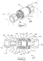
- Figure 2 shows a cross section view of this disconnected quick coupling 100.
- the female component 127 of quick coupling 100 is composed primarily of female socket 105, collar 102, shuttle 104 and socket cap 103.
- socket cap 103 screws into female socket 105 and static O-ring 109 reliably seals the joint between these two parts.
- Shuttle 104 is slidable onto female socket 105.
- shuttle 104 contains a set of six detent balls 107 evenly spaced around the diameter located in holes 125. Locking collar 102 slides on both the female socket 105 and the shuttle 104.
- Spring 110 inside collar 102, is compressed between collar retaining ring 111 and shuttle 104.
- Female socket 105 has holes 118 between collar retaining ring 111 and shuttle 104.
- Female socket 105 has holes 118 for a second set of detent balls 106.
- detent balls 107 and 106 can be replaced by cylindrical detents or detents of another shape. These detent balls are also referred to as detents.
- Male plug 101 and socket cap 103 have interface connections, 112 and 113 respectively, to adapt the quick coupling 100 to other pipes or fittings.
- these interface connections can be either tapered or straight threads, compression type fittings, direct weld connections or other known connection means, without departing from the novel scope of the present invention.
- Tapered pipe thread interface connections 112 and 113 are shown in the quick coupling of Figures 1-6 .
- male plug 101, female socket 105 and socket cap 103 are constructed of stainless steel. These are the surfaces in contact with the gas or liquid inside quick coupling 100. For high purity gases and many other industrial processes, the chemical inertness and stability of stainless steel is desired. For other applications such as compressed air duty, other lower cost metals can be used for these parts.
- the locking collar 102 is also made of stainless steel as are detent balls 106 and 107, spring 110 and retaining ring 111; shuttle 104 is made of high tin bronze. Both high tin bronze and stainless steel are good materials for use inside vacuum chambers and allow the entire quick coupling 100 to be used inside a process vacuum chamber with minimal detrimental effect to the vacuum or process.
- Dynamic O-ring 108 and static O-ring 109 are preferably made of synthetic rubber and fluoropolymer elastomer, such as Viton®, but can also be any sealing material compatible with the application where the quick coupling is used.
- quick coupling 100 has a single dynamic sealing O-ring 108 that is located in an O-ring groove 122 on male plug 101.
- This O-ring 108 being on male plug 101, protects the male plug sealing surface 123 from damage when the male plug 101 is loose, that is, not inserted in female socket 105. This is important when the quick coupling is used in a high vacuum application where a small scratch in the sealing surface will cause an intolerable leak.
- An additional advantage of having the primary dynamic seal on the male plug is that it is readily accessible for inspection and replacement.
- Figure 3 depicts the quick coupling 100, wherein male plug 101 is pushed into female socket 105 up to the point where plug shoulder 131 contacts collar face 130. At the position illustrated, no movement of collar 102 or shuttle 104 has occurred yet. This view is shown for overall quick coupling operation clarity.
- Figure 5 shows a sectional view of the connected quick coupling 100.
- collar 102 moves automatically from the position shown in Figure 4 to the locked position shown here. This occurs as detent balls 107 move into socket recess 117 and the expansion force of spring 110 pushes collar 102 away from shuttle 104. Collar 102 is automatically caused to slide back until collar shoulder 151 hits shuttle 104. Shuttle 104 is prevented from moving relative to female socket 105 in this the locked position as detent balls 107 are in socket recess 117.
- the automatic movement of collar 102 into the locked position enables the quick coupling connected state to be achieved by simply pushing the male plug 101 into female socket 105 and therefore a true one-handed connection operation is achieved.
- 'automatic' and 'automatically' are used to differentiate the manual pushing of male plug 101 into female socket 105 from the final toggling sliding motion of collar 102 into the locked position.
- plug 101 is manually pushed into socket 105. As this is done, plug shoulder encounters collar face 130 and pushes collar 102 back. As plug 101 nears the connected position in relation to socket 105, collar 102 reaches the point where 'automatic' motion occurs as described above.
- the manual motion of pushing male plug 101 into female socket 105 stops as plug shoulder 131 hits socket face 132. Collar 102 continues to slide back along socket 105 of its own accord 'automatically' until stopping in the locked position.
- FIG. 6 shows a perspective view of the connected quick coupling 100. It will be seen that this locked position or connected state is stable and that the quick coupling will remain connected until the collar is manually manipulated to effect disconnection.
- Quick coupling 100 can be disconnected by simply pulling collar 102 toward male plug 101 while the female socket 105 (and socket cap 103) is held stationary, typically by action of the attached conduit, so that only one hand is needed to effect disconnection.
- detent balls 107 move out of socket recess 117 and into collar recess 119.
- Face 130 of collar 102 now encounters plug shoulder 131 and pushes male plug 101 out of female socket 105.
- detent balls 106 move out of male plug recess 115 and up plug ramp 116.
- collar 102 reaches the position shown in Figure 3 , the male plug 101 is free to come out of female socket 105. The outward motion of collar 102 tends to pop male plug 101 out into the hand of the user with an audible click.
- quick coupling 100 achieves the design goals of one-handed push-to-connect and one-handed pull-to-disconnect operation. In both states the operation is accompanied by audible, tactile and visual feedback communicating successful completion to the user. Importantly, quick coupling 100 achieves this goal with a simple design having only one energizing spring and one dynamic seal. Additionally, the male plug 101 is a single part (not including the O-ring) that can be readily installed on a number of devices for connection into a single female supply component.
- the quick coupling 100 of the present invention can be used for vacuum and also high pressure fluid applications such as hydraulic, pneumatic and water lines.
- the inventive quick coupling can also have utility in other devices such as electrical connectors (e.g., single- or multiple-conductor), power take-offs and tool holders (e.g., for use with drill bits, end mills, surgical implements, hand tools, etc.).
- electrical connectors e.g., single- or multiple-conductor
- power take-offs and tool holders e.g., for use with drill bits, end mills, surgical implements, hand tools, etc.
- the inventive quick coupling can be readily configured to transmit torque by having rotational locking features such as splines or keyways.
- Other potential applications will be apparent to those skilled in the art.
Landscapes
- Engineering & Computer Science (AREA)
- General Engineering & Computer Science (AREA)
- Mechanical Engineering (AREA)
- Quick-Acting Or Multi-Walled Pipe Joints (AREA)
Claims (6)
- Raccord rapide à raccordement par poussée et séparation par traction (100) comprenant :a) une prise femelle (105) ayant une extrémité ouverte pour recevoir une fiche mâle (101), un évidement (117) pour accepter un premier cran (107) et des trous (118) pour contenir un second cran (106) ;b) une navette (104) apte à coulisser le long de l'extérieur de la prise (105), ladite navette (104) ayant des trous (125) pour contenir le premier cran (107) ;c) un collier (102) apte à coulisser le long de l'extérieur à la fois de la prise femelle (105) et de la navette (104), le collier (102) ayant un évidement (119) pour le premier cran (107) et une rampe (120) pour le second cran (106) ;d) un ressort (110) comprimé entre le collier (102) et la navette (104) ;e) une fiche mâle (101) apte à être introduite dans la prise femelle (105), ladite fiche (101) ayant un évidement (115) pour le second cran (106) ;f) dans lequel un état raccordé stable est établi lorsque la fiche (101) est introduite dans la prise femelle (105) et le collier (102), initialement poussé par la fiche mâle (101), coulisse automatiquement jusqu'à une position verrouillée ;g) et dans lequel un état séparé stable est atteint par traction manuelle du collier (102) vers l'extrémité ouverte de la prise (105).
- Raccord rapide selon la revendication 1, dans lequel la fiche mâle comprend un joint torique (108).
- Raccord rapide selon la revendication 1, dans lequel le ressort (110) maintient à la fois les états raccordés et séparés.
- Raccord rapide selon la revendication 1, dans lequel l'état raccordé stable est maintenu par le ressort (110) appliquant une force pour pousser le collier (102) à l'opposé de la navette (104), la navette (104) étant verrouillée à la prise femelle (105) lorsque le premier cran (107) est contraint entre l'évidement de prise femelle (117) et les trous de cran de navette (125).
- Raccord rapide selon la revendication 1, dans lequel, dans l'état raccordé stable, la fiche mâle (101) est verrouillée dans la prise femelle (105) lorsque le second cran (106) est contraint à l'intérieur de l'évidement de fiche mâle (115) et des trous de prise femelle (118).
- Raccord rapide selon la revendication 1, dans lequel l'état séparé stable est maintenu par le ressort (110) appliquant une force pour caler le premier cran (107) entre l'évidement de collier (119) et la prise femelle (105) .
Applications Claiming Priority (2)
| Application Number | Priority Date | Filing Date | Title |
|---|---|---|---|
| US201562152818P | 2015-04-24 | 2015-04-24 | |
| PCT/US2016/029105 WO2016172666A1 (fr) | 2015-04-24 | 2016-04-25 | Raccord rapide à raccordement par poussée et séparation par traction |
Publications (2)
| Publication Number | Publication Date |
|---|---|
| EP3286477A1 EP3286477A1 (fr) | 2018-02-28 |
| EP3286477B1 true EP3286477B1 (fr) | 2020-01-29 |
Family
ID=55861302
Family Applications (1)
| Application Number | Title | Priority Date | Filing Date |
|---|---|---|---|
| EP16719739.1A Active EP3286477B1 (fr) | 2015-04-24 | 2016-04-25 | Raccord rapide à raccordement par poussée et séparation par traction |
Country Status (5)
| Country | Link |
|---|---|
| US (1) | US10989343B2 (fr) |
| EP (1) | EP3286477B1 (fr) |
| JP (1) | JP2018515731A (fr) |
| KR (1) | KR20170139138A (fr) |
| WO (1) | WO2016172666A1 (fr) |
Families Citing this family (6)
| Publication number | Priority date | Publication date | Assignee | Title |
|---|---|---|---|---|
| US10989343B2 (en) | 2015-04-24 | 2021-04-27 | General Plasma Inc. | Push-to-connect and pull-to-disconnect quick coupling |
| US11014258B2 (en) * | 2016-12-20 | 2021-05-25 | Gea Food Solutions Germany Gmbh | Delay unit, unrolling device, cutting machine and method for providing separating material |
| EP3379129B1 (fr) * | 2017-03-23 | 2022-09-28 | Georg Fischer JRG AG | Raccord |
| US11988313B2 (en) | 2019-03-26 | 2024-05-21 | Rely Innovations, Inc. | Coupler for fire extinguisher nozzle accessory |
| EP3789648B1 (fr) * | 2019-09-06 | 2024-01-03 | ODU GmbH & Co. KG | Connecteur à verrouillage de bille |
| EP4011559A1 (fr) * | 2020-12-09 | 2022-06-15 | Dubuis et Cie | Dispositif doté d'un système de couplage rapide pour fixer une tête interchangeable |
Family Cites Families (55)
| Publication number | Priority date | Publication date | Assignee | Title |
|---|---|---|---|---|
| US1873914A (en) * | 1928-12-31 | 1932-08-23 | Adams Grease Gun Corp | High pressure coupler |
| US2092116A (en) | 1935-11-07 | 1937-09-07 | Fred E Hansen | Hose coupling |
| US2069434A (en) | 1936-03-16 | 1937-02-02 | Aro Equipment Corp | Speed coupler |
| US2279146A (en) | 1941-04-12 | 1942-04-07 | Lincoln Eng Co | Coupler |
| US2297548A (en) | 1941-09-22 | 1942-09-29 | Lincoln Eng Co | Coupler |
| US2377812A (en) | 1943-01-20 | 1945-06-05 | Albert T Scheiwer | Coupling |
| US2473973A (en) | 1945-05-21 | 1949-06-21 | Albert T Scheiwer | Coupling |
| US2428637A (en) | 1945-05-21 | 1947-10-07 | Albert T Scheiwer | Coupling |
| US2451218A (en) | 1946-07-13 | 1948-10-12 | Bendix Aviat Corp | Quick disconnect coupling |
| US2521701A (en) | 1946-12-27 | 1950-09-12 | Clarence E Earle | Coupling |
| US2512999A (en) | 1947-07-29 | 1950-06-27 | Earl F Bruning | Coupling |
| US2643140A (en) | 1948-04-29 | 1953-06-23 | Albert T Scheiwer | Coupling |
| US2568516A (en) | 1948-05-19 | 1951-09-18 | Albert T Scheiwer | Coupling |
| US2674469A (en) | 1948-07-30 | 1954-04-06 | Clarence E Earle | Fluid coupling |
| US2860893A (en) | 1955-05-09 | 1958-11-18 | Snap Tite Inc | Ball detent type coupling with break-away feature |
| US2797110A (en) | 1956-04-04 | 1957-06-25 | Carl A Covington | Ball detent coupling |
| US2898797A (en) | 1956-05-28 | 1959-08-11 | Bronstein Harry | Cam operated ball detent coupling pin |
| US2941835A (en) | 1957-06-26 | 1960-06-21 | Musser C Walton | Parachute release connection |
| US3032359A (en) | 1958-05-05 | 1962-05-01 | Crawford Fitting Co | Quick connect coupling |
| US3138393A (en) | 1960-06-20 | 1964-06-23 | George E Livingston | Coupling for substantially axially fixed conduits |
| US3112767A (en) * | 1960-10-21 | 1963-12-03 | Crawford Fitting Co | Quick-connect coupling |
| US3178213A (en) | 1963-01-10 | 1965-04-13 | Robert J Nelson | Catch mechanism |
| US3276799A (en) | 1964-01-29 | 1966-10-04 | E & R Lab Service Corp | Cable quick disconnect |
| US3498324A (en) | 1967-03-17 | 1970-03-03 | Snap Tite Inc | Quick connect high pressure coupling |
| US3674051A (en) | 1971-05-14 | 1972-07-04 | Safe Way Hydraulics | Hydraulic coupler |
| DE2715395A1 (de) * | 1977-04-06 | 1978-10-12 | Argus Gmbh | Schnellverschlusskupplung fuer hydraulikleitungen |
| US4219048A (en) * | 1978-03-08 | 1980-08-26 | Ekman Engineering Ag | Coupling device |
| WO1980001311A1 (fr) | 1978-12-20 | 1980-06-26 | Abnox Ag | Accouplement de tuyaux |
| US4249572A (en) | 1980-02-04 | 1981-02-10 | Deere & Co | Self-relieving fluid coupling |
| JPS57139706A (en) | 1981-02-24 | 1982-08-28 | Nippon Telegr & Teleph Corp <Ntt> | Unit of optical fiber core |
| JPS6119211Y2 (fr) * | 1981-02-26 | 1986-06-10 | ||
| JPS59175783A (ja) | 1983-03-25 | 1984-10-04 | Fujitsu Ltd | 半導体発光装置 |
| JPS59175783U (ja) * | 1983-05-12 | 1984-11-24 | 日東工器株式会社 | ホース接続用管継手 |
| FR2630524B1 (fr) | 1988-04-20 | 1990-08-03 | Parker Hannifin Rak Sa | Coupleur a clapets a douille exterieure mobile |
| US4924909A (en) | 1989-03-20 | 1990-05-15 | Snap-Tite, Inc. | Semi-balanced staggered locking coupling |
| US5211197A (en) | 1992-01-03 | 1993-05-18 | Aeroquip Corporation | Quick disconnect liquid line coupling with volumertric expansion couping element |
| US5255714A (en) | 1992-11-13 | 1993-10-26 | Perfecting Services, Inc. | Quick-action fluid coupling |
| JP3211489B2 (ja) | 1993-06-29 | 2001-09-25 | 石川島播磨重工業株式会社 | 高温腐蝕摩耗特性の評価方法 |
| JPH0712693U (ja) * | 1993-07-29 | 1995-03-03 | 日東工器株式会社 | 管継手 |
| US5323812A (en) * | 1993-10-05 | 1994-06-28 | Snap-Tite, Inc. | Pressure-locked coupling |
| US5540250A (en) | 1994-03-22 | 1996-07-30 | Perfecting Coupling Company | Quick-disconnect fluid coupling |
| US5445358A (en) | 1994-12-16 | 1995-08-29 | Parker-Hannifin Corporation | Exhaust type quick action coupler |
| JP2909020B2 (ja) * | 1996-06-11 | 1999-06-23 | ナスコフィッティング株式会社 | 管継手 |
| IT1289947B1 (it) | 1997-02-21 | 1998-10-19 | Faster Srl | Innesto rapido |
| JP3383560B2 (ja) * | 1997-10-06 | 2003-03-04 | 日東工器株式会社 | 管継手 |
| JP3313675B2 (ja) * | 1999-10-18 | 2002-08-12 | 日東工器株式会社 | 管継手用ソケット |
| US6702254B2 (en) | 2001-03-22 | 2004-03-09 | Hoke, Inc. | Universal safety coupler |
| US8251606B2 (en) | 2007-08-31 | 2012-08-28 | The Blanchard Patent Holding Company, Llc | Fastener and assembly utilizing the same |
| US8246085B2 (en) | 2007-09-27 | 2012-08-21 | Nitto Kohki Co., Ltd. | Pipe coupling and female pipe coupling member |
| JP5317760B2 (ja) * | 2008-02-28 | 2013-10-16 | 日東工器株式会社 | 管継手用のソケット及び管継手 |
| US7926783B1 (en) | 2009-12-08 | 2011-04-19 | Liu Hsiu-Hsiung | Safety type quick release connector |
| US8303000B2 (en) | 2010-09-13 | 2012-11-06 | Liu Hsiu-Hsiung | Quick release connector |
| CN202812595U (zh) | 2012-09-12 | 2013-03-20 | 达钺实业股份有限公司 | 快速接头 |
| US20140076417A1 (en) * | 2012-09-14 | 2014-03-20 | I-Pao LIN | Quickly-operated adaptor |
| US10989343B2 (en) | 2015-04-24 | 2021-04-27 | General Plasma Inc. | Push-to-connect and pull-to-disconnect quick coupling |
-
2016
- 2016-04-25 US US15/568,295 patent/US10989343B2/en active Active
- 2016-04-25 WO PCT/US2016/029105 patent/WO2016172666A1/fr active Application Filing
- 2016-04-25 EP EP16719739.1A patent/EP3286477B1/fr active Active
- 2016-04-25 KR KR1020177033801A patent/KR20170139138A/ko unknown
- 2016-04-25 JP JP2018506812A patent/JP2018515731A/ja active Pending
Non-Patent Citations (1)
| Title |
|---|
| None * |
Also Published As
| Publication number | Publication date |
|---|---|
| KR20170139138A (ko) | 2017-12-18 |
| EP3286477A1 (fr) | 2018-02-28 |
| US10989343B2 (en) | 2021-04-27 |
| US20180112808A1 (en) | 2018-04-26 |
| WO2016172666A1 (fr) | 2016-10-27 |
| JP2018515731A (ja) | 2018-06-14 |
Similar Documents
| Publication | Publication Date | Title |
|---|---|---|
| EP3286477B1 (fr) | Raccord rapide à raccordement par poussée et séparation par traction | |
| US8720487B2 (en) | Grease delivery receiver and nozzle couplable without fluid pressure bleed-down and having pressurization lockout and flush face coupling | |
| AU709285B2 (en) | Fluid couplings | |
| US7469933B2 (en) | Quick connect coupling with disconnect lock | |
| US5232021A (en) | Probe member for undersea hydraulic coupling | |
| US9617819B2 (en) | Subsea collet connection system | |
| US9482379B2 (en) | Twist-to-connect dry break coupling | |
| US10253911B1 (en) | Quick disconnect coupling with selective mating capability | |
| US6866064B2 (en) | Coupling assembly having a coupling member removably securable in an apparatus | |
| US3351362A (en) | Quick-disconnective coupling | |
| US3566918A (en) | Quick connect and disconnect fluid conveying coupling | |
| EP0862710B1 (fr) | Coupleur femelle a faibles pertes | |
| US10302232B2 (en) | Self sealing end fitting | |
| US8042571B2 (en) | Rigid mount anti-leak fluid coupler | |
| EP1859190B1 (fr) | Raccord rapide a verrou de degagement | |
| US20240052960A1 (en) | Nipple With Relief Valve | |
| EP1481186B1 (fr) | Robinet a raccordement rapide et tube de raccordement interagissant avec ledit robinet | |
| ES2818118T3 (es) | Un acoplamiento de ajuste rápido | |
| GB2585950A (en) | Safety connector | |
| EP2103860A2 (fr) | Coupleur anti-fuite pour fluides à montage rigide | |
| JP2005024085A (ja) | 管継手 |
Legal Events
| Date | Code | Title | Description |
|---|---|---|---|
| STAA | Information on the status of an ep patent application or granted ep patent |
Free format text: STATUS: THE INTERNATIONAL PUBLICATION HAS BEEN MADE |
|
| PUAI | Public reference made under article 153(3) epc to a published international application that has entered the european phase |
Free format text: ORIGINAL CODE: 0009012 |
|
| STAA | Information on the status of an ep patent application or granted ep patent |
Free format text: STATUS: REQUEST FOR EXAMINATION WAS MADE |
|
| 17P | Request for examination filed |
Effective date: 20171024 |
|
| AK | Designated contracting states |
Kind code of ref document: A1 Designated state(s): AL AT BE BG CH CY CZ DE DK EE ES FI FR GB GR HR HU IE IS IT LI LT LU LV MC MK MT NL NO PL PT RO RS SE SI SK SM TR |
|
| AX | Request for extension of the european patent |
Extension state: BA ME |
|
| DAV | Request for validation of the european patent (deleted) | ||
| DAX | Request for extension of the european patent (deleted) | ||
| GRAP | Despatch of communication of intention to grant a patent |
Free format text: ORIGINAL CODE: EPIDOSNIGR1 |
|
| STAA | Information on the status of an ep patent application or granted ep patent |
Free format text: STATUS: GRANT OF PATENT IS INTENDED |
|
| INTG | Intention to grant announced |
Effective date: 20190606 |
|
| GRAS | Grant fee paid |
Free format text: ORIGINAL CODE: EPIDOSNIGR3 |
|
| GRAA | (expected) grant |
Free format text: ORIGINAL CODE: 0009210 |
|
| STAA | Information on the status of an ep patent application or granted ep patent |
Free format text: STATUS: THE PATENT HAS BEEN GRANTED |
|
| RAP1 | Party data changed (applicant data changed or rights of an application transferred) |
Owner name: GENERAL PLASMA INC. |
|
| AK | Designated contracting states |
Kind code of ref document: B1 Designated state(s): AL AT BE BG CH CY CZ DE DK EE ES FI FR GB GR HR HU IE IS IT LI LT LU LV MC MK MT NL NO PL PT RO RS SE SI SK SM TR |
|
| REG | Reference to a national code |
Ref country code: GB Ref legal event code: FG4D |
|
| REG | Reference to a national code |
Ref country code: CH Ref legal event code: EP |
|
| REG | Reference to a national code |
Ref country code: AT Ref legal event code: REF Ref document number: 1228746 Country of ref document: AT Kind code of ref document: T Effective date: 20200215 |
|
| REG | Reference to a national code |
Ref country code: IE Ref legal event code: FG4D |
|
| REG | Reference to a national code |
Ref country code: DE Ref legal event code: R096 Ref document number: 602016028689 Country of ref document: DE |
|
| REG | Reference to a national code |
Ref country code: NL Ref legal event code: MP Effective date: 20200129 |
|
| PG25 | Lapsed in a contracting state [announced via postgrant information from national office to epo] |
Ref country code: NO Free format text: LAPSE BECAUSE OF FAILURE TO SUBMIT A TRANSLATION OF THE DESCRIPTION OR TO PAY THE FEE WITHIN THE PRESCRIBED TIME-LIMIT Effective date: 20200429 Ref country code: PT Free format text: LAPSE BECAUSE OF FAILURE TO SUBMIT A TRANSLATION OF THE DESCRIPTION OR TO PAY THE FEE WITHIN THE PRESCRIBED TIME-LIMIT Effective date: 20200621 Ref country code: RS Free format text: LAPSE BECAUSE OF FAILURE TO SUBMIT A TRANSLATION OF THE DESCRIPTION OR TO PAY THE FEE WITHIN THE PRESCRIBED TIME-LIMIT Effective date: 20200129 Ref country code: FI Free format text: LAPSE BECAUSE OF FAILURE TO SUBMIT A TRANSLATION OF THE DESCRIPTION OR TO PAY THE FEE WITHIN THE PRESCRIBED TIME-LIMIT Effective date: 20200129 |
|
| PGFP | Annual fee paid to national office [announced via postgrant information from national office to epo] |
Ref country code: DE Payment date: 20200528 Year of fee payment: 5 |
|
| REG | Reference to a national code |
Ref country code: LT Ref legal event code: MG4D |
|
| PG25 | Lapsed in a contracting state [announced via postgrant information from national office to epo] |
Ref country code: HR Free format text: LAPSE BECAUSE OF FAILURE TO SUBMIT A TRANSLATION OF THE DESCRIPTION OR TO PAY THE FEE WITHIN THE PRESCRIBED TIME-LIMIT Effective date: 20200129 Ref country code: GR Free format text: LAPSE BECAUSE OF FAILURE TO SUBMIT A TRANSLATION OF THE DESCRIPTION OR TO PAY THE FEE WITHIN THE PRESCRIBED TIME-LIMIT Effective date: 20200430 Ref country code: LV Free format text: LAPSE BECAUSE OF FAILURE TO SUBMIT A TRANSLATION OF THE DESCRIPTION OR TO PAY THE FEE WITHIN THE PRESCRIBED TIME-LIMIT Effective date: 20200129 Ref country code: IS Free format text: LAPSE BECAUSE OF FAILURE TO SUBMIT A TRANSLATION OF THE DESCRIPTION OR TO PAY THE FEE WITHIN THE PRESCRIBED TIME-LIMIT Effective date: 20200529 Ref country code: SE Free format text: LAPSE BECAUSE OF FAILURE TO SUBMIT A TRANSLATION OF THE DESCRIPTION OR TO PAY THE FEE WITHIN THE PRESCRIBED TIME-LIMIT Effective date: 20200129 Ref country code: BG Free format text: LAPSE BECAUSE OF FAILURE TO SUBMIT A TRANSLATION OF THE DESCRIPTION OR TO PAY THE FEE WITHIN THE PRESCRIBED TIME-LIMIT Effective date: 20200429 |
|
| PG25 | Lapsed in a contracting state [announced via postgrant information from national office to epo] |
Ref country code: NL Free format text: LAPSE BECAUSE OF FAILURE TO SUBMIT A TRANSLATION OF THE DESCRIPTION OR TO PAY THE FEE WITHIN THE PRESCRIBED TIME-LIMIT Effective date: 20200129 |
|
| PG25 | Lapsed in a contracting state [announced via postgrant information from national office to epo] |
Ref country code: ES Free format text: LAPSE BECAUSE OF FAILURE TO SUBMIT A TRANSLATION OF THE DESCRIPTION OR TO PAY THE FEE WITHIN THE PRESCRIBED TIME-LIMIT Effective date: 20200129 Ref country code: RO Free format text: LAPSE BECAUSE OF FAILURE TO SUBMIT A TRANSLATION OF THE DESCRIPTION OR TO PAY THE FEE WITHIN THE PRESCRIBED TIME-LIMIT Effective date: 20200129 Ref country code: CZ Free format text: LAPSE BECAUSE OF FAILURE TO SUBMIT A TRANSLATION OF THE DESCRIPTION OR TO PAY THE FEE WITHIN THE PRESCRIBED TIME-LIMIT Effective date: 20200129 Ref country code: SM Free format text: LAPSE BECAUSE OF FAILURE TO SUBMIT A TRANSLATION OF THE DESCRIPTION OR TO PAY THE FEE WITHIN THE PRESCRIBED TIME-LIMIT Effective date: 20200129 Ref country code: EE Free format text: LAPSE BECAUSE OF FAILURE TO SUBMIT A TRANSLATION OF THE DESCRIPTION OR TO PAY THE FEE WITHIN THE PRESCRIBED TIME-LIMIT Effective date: 20200129 Ref country code: LT Free format text: LAPSE BECAUSE OF FAILURE TO SUBMIT A TRANSLATION OF THE DESCRIPTION OR TO PAY THE FEE WITHIN THE PRESCRIBED TIME-LIMIT Effective date: 20200129 Ref country code: DK Free format text: LAPSE BECAUSE OF FAILURE TO SUBMIT A TRANSLATION OF THE DESCRIPTION OR TO PAY THE FEE WITHIN THE PRESCRIBED TIME-LIMIT Effective date: 20200129 Ref country code: SK Free format text: LAPSE BECAUSE OF FAILURE TO SUBMIT A TRANSLATION OF THE DESCRIPTION OR TO PAY THE FEE WITHIN THE PRESCRIBED TIME-LIMIT Effective date: 20200129 |
|
| REG | Reference to a national code |
Ref country code: DE Ref legal event code: R097 Ref document number: 602016028689 Country of ref document: DE |
|
| REG | Reference to a national code |
Ref country code: AT Ref legal event code: MK05 Ref document number: 1228746 Country of ref document: AT Kind code of ref document: T Effective date: 20200129 |
|
| PG25 | Lapsed in a contracting state [announced via postgrant information from national office to epo] |
Ref country code: MC Free format text: LAPSE BECAUSE OF FAILURE TO SUBMIT A TRANSLATION OF THE DESCRIPTION OR TO PAY THE FEE WITHIN THE PRESCRIBED TIME-LIMIT Effective date: 20200129 |
|
| REG | Reference to a national code |
Ref country code: CH Ref legal event code: PL |
|
| PLBE | No opposition filed within time limit |
Free format text: ORIGINAL CODE: 0009261 |
|
| STAA | Information on the status of an ep patent application or granted ep patent |
Free format text: STATUS: NO OPPOSITION FILED WITHIN TIME LIMIT |
|
| 26N | No opposition filed |
Effective date: 20201030 |
|
| PG25 | Lapsed in a contracting state [announced via postgrant information from national office to epo] |
Ref country code: LI Free format text: LAPSE BECAUSE OF NON-PAYMENT OF DUE FEES Effective date: 20200430 Ref country code: IT Free format text: LAPSE BECAUSE OF FAILURE TO SUBMIT A TRANSLATION OF THE DESCRIPTION OR TO PAY THE FEE WITHIN THE PRESCRIBED TIME-LIMIT Effective date: 20200129 Ref country code: AT Free format text: LAPSE BECAUSE OF FAILURE TO SUBMIT A TRANSLATION OF THE DESCRIPTION OR TO PAY THE FEE WITHIN THE PRESCRIBED TIME-LIMIT Effective date: 20200129 Ref country code: FR Free format text: LAPSE BECAUSE OF NON-PAYMENT OF DUE FEES Effective date: 20200430 Ref country code: CH Free format text: LAPSE BECAUSE OF NON-PAYMENT OF DUE FEES Effective date: 20200430 Ref country code: LU Free format text: LAPSE BECAUSE OF NON-PAYMENT OF DUE FEES Effective date: 20200425 |
|
| REG | Reference to a national code |
Ref country code: BE Ref legal event code: MM Effective date: 20200430 |
|
| PG25 | Lapsed in a contracting state [announced via postgrant information from national office to epo] |
Ref country code: PL Free format text: LAPSE BECAUSE OF FAILURE TO SUBMIT A TRANSLATION OF THE DESCRIPTION OR TO PAY THE FEE WITHIN THE PRESCRIBED TIME-LIMIT Effective date: 20200129 Ref country code: BE Free format text: LAPSE BECAUSE OF NON-PAYMENT OF DUE FEES Effective date: 20200430 Ref country code: SI Free format text: LAPSE BECAUSE OF FAILURE TO SUBMIT A TRANSLATION OF THE DESCRIPTION OR TO PAY THE FEE WITHIN THE PRESCRIBED TIME-LIMIT Effective date: 20200129 |
|
| GBPC | Gb: european patent ceased through non-payment of renewal fee |
Effective date: 20200429 |
|
| PG25 | Lapsed in a contracting state [announced via postgrant information from national office to epo] |
Ref country code: GB Free format text: LAPSE BECAUSE OF NON-PAYMENT OF DUE FEES Effective date: 20200429 Ref country code: IE Free format text: LAPSE BECAUSE OF NON-PAYMENT OF DUE FEES Effective date: 20200425 |
|
| REG | Reference to a national code |
Ref country code: DE Ref legal event code: R119 Ref document number: 602016028689 Country of ref document: DE |
|
| PG25 | Lapsed in a contracting state [announced via postgrant information from national office to epo] |
Ref country code: DE Free format text: LAPSE BECAUSE OF NON-PAYMENT OF DUE FEES Effective date: 20211103 |
|
| PG25 | Lapsed in a contracting state [announced via postgrant information from national office to epo] |
Ref country code: TR Free format text: LAPSE BECAUSE OF FAILURE TO SUBMIT A TRANSLATION OF THE DESCRIPTION OR TO PAY THE FEE WITHIN THE PRESCRIBED TIME-LIMIT Effective date: 20200129 Ref country code: MT Free format text: LAPSE BECAUSE OF FAILURE TO SUBMIT A TRANSLATION OF THE DESCRIPTION OR TO PAY THE FEE WITHIN THE PRESCRIBED TIME-LIMIT Effective date: 20200129 Ref country code: CY Free format text: LAPSE BECAUSE OF FAILURE TO SUBMIT A TRANSLATION OF THE DESCRIPTION OR TO PAY THE FEE WITHIN THE PRESCRIBED TIME-LIMIT Effective date: 20200129 |
|
| PG25 | Lapsed in a contracting state [announced via postgrant information from national office to epo] |
Ref country code: MK Free format text: LAPSE BECAUSE OF FAILURE TO SUBMIT A TRANSLATION OF THE DESCRIPTION OR TO PAY THE FEE WITHIN THE PRESCRIBED TIME-LIMIT Effective date: 20200129 Ref country code: AL Free format text: LAPSE BECAUSE OF FAILURE TO SUBMIT A TRANSLATION OF THE DESCRIPTION OR TO PAY THE FEE WITHIN THE PRESCRIBED TIME-LIMIT Effective date: 20200129 |