EP3286289B1 - Threaded tubular connection provided with a metallic coating on the threading and on the sealing surface - Google Patents
Threaded tubular connection provided with a metallic coating on the threading and on the sealing surface Download PDFInfo
- Publication number
- EP3286289B1 EP3286289B1 EP16722065.6A EP16722065A EP3286289B1 EP 3286289 B1 EP3286289 B1 EP 3286289B1 EP 16722065 A EP16722065 A EP 16722065A EP 3286289 B1 EP3286289 B1 EP 3286289B1
- Authority
- EP
- European Patent Office
- Prior art keywords
- layer
- metallic
- tubular connection
- threaded tubular
- connection according
- Prior art date
- Legal status (The legal status is an assumption and is not a legal conclusion. Google has not performed a legal analysis and makes no representation as to the accuracy of the status listed.)
- Active
Links
- 238000007789 sealing Methods 0.000 title claims description 33
- 238000000576 coating method Methods 0.000 title description 21
- 239000011248 coating agent Substances 0.000 title description 16
- 239000000314 lubricant Substances 0.000 claims description 64
- 238000002161 passivation Methods 0.000 claims description 64
- 238000005260 corrosion Methods 0.000 claims description 54
- JBQYATWDVHIOAR-UHFFFAOYSA-N tellanylidenegermanium Chemical compound [Te]=[Ge] JBQYATWDVHIOAR-UHFFFAOYSA-N 0.000 claims description 40
- PXHVJJICTQNCMI-UHFFFAOYSA-N Nickel Chemical group [Ni] PXHVJJICTQNCMI-UHFFFAOYSA-N 0.000 claims description 38
- VYPSYNLAJGMNEJ-UHFFFAOYSA-N Silicium dioxide Chemical compound O=[Si]=O VYPSYNLAJGMNEJ-UHFFFAOYSA-N 0.000 claims description 33
- 229920005989 resin Polymers 0.000 claims description 32
- 239000011347 resin Substances 0.000 claims description 32
- 229910052751 metal Inorganic materials 0.000 claims description 28
- 239000002184 metal Substances 0.000 claims description 28
- 229910045601 alloy Inorganic materials 0.000 claims description 23
- 239000000956 alloy Substances 0.000 claims description 23
- 229910000831 Steel Inorganic materials 0.000 claims description 19
- 239000010959 steel Substances 0.000 claims description 19
- 230000004888 barrier function Effects 0.000 claims description 18
- 239000007787 solid Substances 0.000 claims description 17
- 239000000377 silicon dioxide Substances 0.000 claims description 16
- QELJHCBNGDEXLD-UHFFFAOYSA-N nickel zinc Chemical compound [Ni].[Zn] QELJHCBNGDEXLD-UHFFFAOYSA-N 0.000 claims description 15
- 239000002245 particle Substances 0.000 claims description 15
- 239000000843 powder Substances 0.000 claims description 14
- 230000000295 complement effect Effects 0.000 claims description 13
- 229910052759 nickel Inorganic materials 0.000 claims description 13
- 239000006229 carbon black Substances 0.000 claims description 12
- 235000019241 carbon black Nutrition 0.000 claims description 12
- 239000011159 matrix material Substances 0.000 claims description 12
- -1 polytetrafluoroethylenes Polymers 0.000 claims description 12
- 239000011651 chromium Substances 0.000 claims description 11
- 239000011777 magnesium Substances 0.000 claims description 11
- 239000011572 manganese Substances 0.000 claims description 11
- 239000000203 mixture Substances 0.000 claims description 11
- 229920001343 polytetrafluoroethylene Polymers 0.000 claims description 11
- XEEYBQQBJWHFJM-UHFFFAOYSA-N Iron Chemical compound [Fe] XEEYBQQBJWHFJM-UHFFFAOYSA-N 0.000 claims description 10
- 229910052500 inorganic mineral Inorganic materials 0.000 claims description 10
- 239000011707 mineral Substances 0.000 claims description 10
- VYZAMTAEIAYCRO-UHFFFAOYSA-N Chromium Chemical compound [Cr] VYZAMTAEIAYCRO-UHFFFAOYSA-N 0.000 claims description 9
- 229910052804 chromium Inorganic materials 0.000 claims description 9
- 239000004215 Carbon black (E152) Substances 0.000 claims description 8
- BFGKITSFLPAWGI-UHFFFAOYSA-N chromium(3+) Chemical compound [Cr+3] BFGKITSFLPAWGI-UHFFFAOYSA-N 0.000 claims description 8
- 229930195733 hydrocarbon Natural products 0.000 claims description 8
- 150000002430 hydrocarbons Chemical class 0.000 claims description 8
- KHYKFSXXGRUKRE-UHFFFAOYSA-J molybdenum(4+) tetracarbamodithioate Chemical class C(N)([S-])=S.[Mo+4].C(N)([S-])=S.C(N)([S-])=S.C(N)([S-])=S KHYKFSXXGRUKRE-UHFFFAOYSA-J 0.000 claims description 8
- 235000012239 silicon dioxide Nutrition 0.000 claims description 8
- 239000004925 Acrylic resin Substances 0.000 claims description 7
- 229920000178 Acrylic resin Polymers 0.000 claims description 7
- 239000004962 Polyamide-imide Substances 0.000 claims description 7
- 229910002056 binary alloy Inorganic materials 0.000 claims description 7
- 238000005553 drilling Methods 0.000 claims description 7
- 229920002312 polyamide-imide Polymers 0.000 claims description 7
- 239000000126 substance Substances 0.000 claims description 7
- 239000003822 epoxy resin Substances 0.000 claims description 6
- CWQXQMHSOZUFJS-UHFFFAOYSA-N molybdenum disulfide Chemical class S=[Mo]=S CWQXQMHSOZUFJS-UHFFFAOYSA-N 0.000 claims description 6
- 229920000647 polyepoxide Polymers 0.000 claims description 6
- 229920005749 polyurethane resin Polymers 0.000 claims description 6
- FYYHWMGAXLPEAU-UHFFFAOYSA-N Magnesium Chemical compound [Mg] FYYHWMGAXLPEAU-UHFFFAOYSA-N 0.000 claims description 5
- PWHULOQIROXLJO-UHFFFAOYSA-N Manganese Chemical compound [Mn] PWHULOQIROXLJO-UHFFFAOYSA-N 0.000 claims description 5
- 239000010439 graphite Substances 0.000 claims description 5
- 229910002804 graphite Inorganic materials 0.000 claims description 5
- LNEPOXFFQSENCJ-UHFFFAOYSA-N haloperidol Chemical compound C1CC(O)(C=2C=CC(Cl)=CC=2)CCN1CCCC(=O)C1=CC=C(F)C=C1 LNEPOXFFQSENCJ-UHFFFAOYSA-N 0.000 claims description 5
- 229910052749 magnesium Inorganic materials 0.000 claims description 5
- 229910052748 manganese Inorganic materials 0.000 claims description 5
- 229920000915 polyvinyl chloride Polymers 0.000 claims description 5
- NIXOWILDQLNWCW-UHFFFAOYSA-N acrylic acid group Chemical group C(C=C)(=O)O NIXOWILDQLNWCW-UHFFFAOYSA-N 0.000 claims description 4
- CHWRSCGUEQEHOH-UHFFFAOYSA-N potassium oxide Chemical compound [O-2].[K+].[K+] CHWRSCGUEQEHOH-UHFFFAOYSA-N 0.000 claims description 2
- 229910001950 potassium oxide Inorganic materials 0.000 claims description 2
- 239000010410 layer Substances 0.000 description 279
- 239000000758 substrate Substances 0.000 description 34
- 230000002093 peripheral effect Effects 0.000 description 19
- 238000000151 deposition Methods 0.000 description 18
- 238000000034 method Methods 0.000 description 17
- 230000003746 surface roughness Effects 0.000 description 17
- 230000007797 corrosion Effects 0.000 description 16
- 230000008569 process Effects 0.000 description 13
- 238000005488 sandblasting Methods 0.000 description 13
- 230000008021 deposition Effects 0.000 description 12
- 239000011701 zinc Substances 0.000 description 12
- 230000001050 lubricating effect Effects 0.000 description 8
- 230000008901 benefit Effects 0.000 description 5
- 238000005868 electrolysis reaction Methods 0.000 description 5
- HCHKCACWOHOZIP-UHFFFAOYSA-N Zinc Chemical group [Zn] HCHKCACWOHOZIP-UHFFFAOYSA-N 0.000 description 4
- 238000006243 chemical reaction Methods 0.000 description 4
- 239000006185 dispersion Substances 0.000 description 4
- 239000012943 hotmelt Substances 0.000 description 4
- 230000003287 optical effect Effects 0.000 description 4
- 239000002904 solvent Substances 0.000 description 4
- 239000002436 steel type Substances 0.000 description 4
- 238000011282 treatment Methods 0.000 description 4
- 229910052725 zinc Inorganic materials 0.000 description 4
- YXFVVABEGXRONW-UHFFFAOYSA-N Toluene Chemical compound CC1=CC=CC=C1 YXFVVABEGXRONW-UHFFFAOYSA-N 0.000 description 3
- 230000000694 effects Effects 0.000 description 3
- 230000009467 reduction Effects 0.000 description 3
- 238000005507 spraying Methods 0.000 description 3
- RYGMFSIKBFXOCR-UHFFFAOYSA-N Copper Chemical compound [Cu] RYGMFSIKBFXOCR-UHFFFAOYSA-N 0.000 description 2
- LFQSCWFLJHTTHZ-UHFFFAOYSA-N Ethanol Chemical compound CCO LFQSCWFLJHTTHZ-UHFFFAOYSA-N 0.000 description 2
- KRHYYFGTRYWZRS-UHFFFAOYSA-N Fluorane Chemical compound F KRHYYFGTRYWZRS-UHFFFAOYSA-N 0.000 description 2
- VEXZGXHMUGYJMC-UHFFFAOYSA-N Hydrochloric acid Chemical compound Cl VEXZGXHMUGYJMC-UHFFFAOYSA-N 0.000 description 2
- 229910000990 Ni alloy Inorganic materials 0.000 description 2
- NBIIXXVUZAFLBC-UHFFFAOYSA-N Phosphoric acid Chemical compound OP(O)(O)=O NBIIXXVUZAFLBC-UHFFFAOYSA-N 0.000 description 2
- FAPWRFPIFSIZLT-UHFFFAOYSA-M Sodium chloride Chemical compound [Na+].[Cl-] FAPWRFPIFSIZLT-UHFFFAOYSA-M 0.000 description 2
- 229910001297 Zn alloy Inorganic materials 0.000 description 2
- 238000009825 accumulation Methods 0.000 description 2
- 239000002253 acid Substances 0.000 description 2
- 230000002378 acidificating effect Effects 0.000 description 2
- 239000008186 active pharmaceutical agent Substances 0.000 description 2
- 239000012736 aqueous medium Substances 0.000 description 2
- JOPOVCBBYLSVDA-UHFFFAOYSA-N chromium(6+) Chemical compound [Cr+6] JOPOVCBBYLSVDA-UHFFFAOYSA-N 0.000 description 2
- 230000000052 comparative effect Effects 0.000 description 2
- 229910052802 copper Inorganic materials 0.000 description 2
- 239000010949 copper Substances 0.000 description 2
- 238000004070 electrodeposition Methods 0.000 description 2
- 230000007613 environmental effect Effects 0.000 description 2
- 239000012535 impurity Substances 0.000 description 2
- 239000007788 liquid Substances 0.000 description 2
- 238000003754 machining Methods 0.000 description 2
- 239000000463 material Substances 0.000 description 2
- 239000002609 medium Substances 0.000 description 2
- 150000001455 metallic ions Chemical class 0.000 description 2
- 150000002739 metals Chemical class 0.000 description 2
- 239000003595 mist Substances 0.000 description 2
- 239000011780 sodium chloride Substances 0.000 description 2
- 239000000243 solution Substances 0.000 description 2
- 238000003860 storage Methods 0.000 description 2
- 229910017518 Cu Zn Inorganic materials 0.000 description 1
- 229910017752 Cu-Zn Inorganic materials 0.000 description 1
- 229910017943 Cu—Zn Inorganic materials 0.000 description 1
- MYMOFIZGZYHOMD-UHFFFAOYSA-N Dioxygen Chemical compound O=O MYMOFIZGZYHOMD-UHFFFAOYSA-N 0.000 description 1
- 239000004593 Epoxy Substances 0.000 description 1
- GRYLNZFGIOXLOG-UHFFFAOYSA-N Nitric acid Chemical compound O[N+]([O-])=O GRYLNZFGIOXLOG-UHFFFAOYSA-N 0.000 description 1
- 239000004698 Polyethylene Substances 0.000 description 1
- QAOWNCQODCNURD-UHFFFAOYSA-N Sulfuric acid Chemical compound OS(O)(=O)=O QAOWNCQODCNURD-UHFFFAOYSA-N 0.000 description 1
- 229910009369 Zn Mg Inorganic materials 0.000 description 1
- 229910007573 Zn-Mg Inorganic materials 0.000 description 1
- 239000003929 acidic solution Substances 0.000 description 1
- 150000007513 acids Chemical class 0.000 description 1
- 239000000654 additive Substances 0.000 description 1
- 239000002318 adhesion promoter Substances 0.000 description 1
- 239000012670 alkaline solution Substances 0.000 description 1
- 125000000217 alkyl group Chemical group 0.000 description 1
- 229910000147 aluminium phosphate Inorganic materials 0.000 description 1
- 239000003963 antioxidant agent Substances 0.000 description 1
- 230000003078 antioxidant effect Effects 0.000 description 1
- 239000007864 aqueous solution Substances 0.000 description 1
- 239000011230 binding agent Substances 0.000 description 1
- 230000015572 biosynthetic process Effects 0.000 description 1
- 229910052797 bismuth Inorganic materials 0.000 description 1
- 239000011575 calcium Substances 0.000 description 1
- 229910052791 calcium Inorganic materials 0.000 description 1
- 235000013869 carnauba wax Nutrition 0.000 description 1
- 239000004203 carnauba wax Substances 0.000 description 1
- 238000004210 cathodic protection Methods 0.000 description 1
- 238000004140 cleaning Methods 0.000 description 1
- 239000010941 cobalt Substances 0.000 description 1
- 229910017052 cobalt Inorganic materials 0.000 description 1
- GUTLYIVDDKVIGB-UHFFFAOYSA-N cobalt atom Chemical compound [Co] GUTLYIVDDKVIGB-UHFFFAOYSA-N 0.000 description 1
- 239000003086 colorant Substances 0.000 description 1
- TVZPLCNGKSPOJA-UHFFFAOYSA-N copper zinc Chemical compound [Cu].[Zn] TVZPLCNGKSPOJA-UHFFFAOYSA-N 0.000 description 1
- 230000008878 coupling Effects 0.000 description 1
- 238000010168 coupling process Methods 0.000 description 1
- 238000005859 coupling reaction Methods 0.000 description 1
- 238000005238 degreasing Methods 0.000 description 1
- 229910001882 dioxygen Inorganic materials 0.000 description 1
- 239000000428 dust Substances 0.000 description 1
- 239000003792 electrolyte Substances 0.000 description 1
- 238000009713 electroplating Methods 0.000 description 1
- 239000003344 environmental pollutant Substances 0.000 description 1
- 230000001747 exhibiting effect Effects 0.000 description 1
- 238000002474 experimental method Methods 0.000 description 1
- 238000000605 extraction Methods 0.000 description 1
- 239000000945 filler Substances 0.000 description 1
- 229920002313 fluoropolymer Polymers 0.000 description 1
- 239000004811 fluoropolymer Substances 0.000 description 1
- 230000036541 health Effects 0.000 description 1
- 229920001519 homopolymer Polymers 0.000 description 1
- 229910052738 indium Inorganic materials 0.000 description 1
- 150000002500 ions Chemical class 0.000 description 1
- 229910052742 iron Inorganic materials 0.000 description 1
- 238000010030 laminating Methods 0.000 description 1
- 230000005923 long-lasting effect Effects 0.000 description 1
- 230000007774 longterm Effects 0.000 description 1
- 238000005461 lubrication Methods 0.000 description 1
- 229910017604 nitric acid Inorganic materials 0.000 description 1
- 239000003921 oil Substances 0.000 description 1
- 239000003129 oil well Substances 0.000 description 1
- 238000005457 optimization Methods 0.000 description 1
- 230000003647 oxidation Effects 0.000 description 1
- 238000007254 oxidation reaction Methods 0.000 description 1
- 239000003208 petroleum Substances 0.000 description 1
- 239000000049 pigment Substances 0.000 description 1
- 239000002798 polar solvent Substances 0.000 description 1
- 231100000719 pollutant Toxicity 0.000 description 1
- 229920000573 polyethylene Polymers 0.000 description 1
- 229920000193 polymethacrylate Polymers 0.000 description 1
- 229920001296 polysiloxane Polymers 0.000 description 1
- 239000002243 precursor Substances 0.000 description 1
- 230000004044 response Effects 0.000 description 1
- 150000003839 salts Chemical class 0.000 description 1
- 239000004576 sand Substances 0.000 description 1
- 238000005479 sherardizing Methods 0.000 description 1
- 239000002356 single layer Substances 0.000 description 1
- 239000001117 sulphuric acid Substances 0.000 description 1
- 235000011149 sulphuric acid Nutrition 0.000 description 1
- 238000004381 surface treatment Methods 0.000 description 1
- 239000004094 surface-active agent Substances 0.000 description 1
- 230000002195 synergetic effect Effects 0.000 description 1
- 229910052718 tin Inorganic materials 0.000 description 1
- XLYOFNOQVPJJNP-UHFFFAOYSA-N water Substances O XLYOFNOQVPJJNP-UHFFFAOYSA-N 0.000 description 1
- XOOUIPVCVHRTMJ-UHFFFAOYSA-L zinc stearate Chemical compound [Zn+2].CCCCCCCCCCCCCCCCCC([O-])=O.CCCCCCCCCCCCCCCCCC([O-])=O XOOUIPVCVHRTMJ-UHFFFAOYSA-L 0.000 description 1
Images
Classifications
-
- C—CHEMISTRY; METALLURGY
- C10—PETROLEUM, GAS OR COKE INDUSTRIES; TECHNICAL GASES CONTAINING CARBON MONOXIDE; FUELS; LUBRICANTS; PEAT
- C10M—LUBRICATING COMPOSITIONS; USE OF CHEMICAL SUBSTANCES EITHER ALONE OR AS LUBRICATING INGREDIENTS IN A LUBRICATING COMPOSITION
- C10M171/00—Lubricating compositions characterised by purely physical criteria, e.g. containing as base-material, thickener or additive, ingredients which are characterised exclusively by their numerically specified physical properties, i.e. containing ingredients which are physically well-defined but for which the chemical nature is either unspecified or only very vaguely indicated
-
- E—FIXED CONSTRUCTIONS
- E21—EARTH OR ROCK DRILLING; MINING
- E21B—EARTH OR ROCK DRILLING; OBTAINING OIL, GAS, WATER, SOLUBLE OR MELTABLE MATERIALS OR A SLURRY OF MINERALS FROM WELLS
- E21B17/00—Drilling rods or pipes; Flexible drill strings; Kellies; Drill collars; Sucker rods; Cables; Casings; Tubings
- E21B17/10—Wear protectors; Centralising devices, e.g. stabilisers
- E21B17/1085—Wear protectors; Blast joints; Hard facing
-
- C—CHEMISTRY; METALLURGY
- C22—METALLURGY; FERROUS OR NON-FERROUS ALLOYS; TREATMENT OF ALLOYS OR NON-FERROUS METALS
- C22C—ALLOYS
- C22C18/00—Alloys based on zinc
-
- C—CHEMISTRY; METALLURGY
- C23—COATING METALLIC MATERIAL; COATING MATERIAL WITH METALLIC MATERIAL; CHEMICAL SURFACE TREATMENT; DIFFUSION TREATMENT OF METALLIC MATERIAL; COATING BY VACUUM EVAPORATION, BY SPUTTERING, BY ION IMPLANTATION OR BY CHEMICAL VAPOUR DEPOSITION, IN GENERAL; INHIBITING CORROSION OF METALLIC MATERIAL OR INCRUSTATION IN GENERAL
- C23C—COATING METALLIC MATERIAL; COATING MATERIAL WITH METALLIC MATERIAL; SURFACE TREATMENT OF METALLIC MATERIAL BY DIFFUSION INTO THE SURFACE, BY CHEMICAL CONVERSION OR SUBSTITUTION; COATING BY VACUUM EVAPORATION, BY SPUTTERING, BY ION IMPLANTATION OR BY CHEMICAL VAPOUR DEPOSITION, IN GENERAL
- C23C28/00—Coating for obtaining at least two superposed coatings either by methods not provided for in a single one of groups C23C2/00 - C23C26/00 or by combinations of methods provided for in subclasses C23C and C25C or C25D
- C23C28/30—Coatings combining at least one metallic layer and at least one inorganic non-metallic layer
- C23C28/32—Coatings combining at least one metallic layer and at least one inorganic non-metallic layer including at least one pure metallic layer
- C23C28/321—Coatings combining at least one metallic layer and at least one inorganic non-metallic layer including at least one pure metallic layer with at least one metal alloy layer
-
- C—CHEMISTRY; METALLURGY
- C23—COATING METALLIC MATERIAL; COATING MATERIAL WITH METALLIC MATERIAL; CHEMICAL SURFACE TREATMENT; DIFFUSION TREATMENT OF METALLIC MATERIAL; COATING BY VACUUM EVAPORATION, BY SPUTTERING, BY ION IMPLANTATION OR BY CHEMICAL VAPOUR DEPOSITION, IN GENERAL; INHIBITING CORROSION OF METALLIC MATERIAL OR INCRUSTATION IN GENERAL
- C23C—COATING METALLIC MATERIAL; COATING MATERIAL WITH METALLIC MATERIAL; SURFACE TREATMENT OF METALLIC MATERIAL BY DIFFUSION INTO THE SURFACE, BY CHEMICAL CONVERSION OR SUBSTITUTION; COATING BY VACUUM EVAPORATION, BY SPUTTERING, BY ION IMPLANTATION OR BY CHEMICAL VAPOUR DEPOSITION, IN GENERAL
- C23C28/00—Coating for obtaining at least two superposed coatings either by methods not provided for in a single one of groups C23C2/00 - C23C26/00 or by combinations of methods provided for in subclasses C23C and C25C or C25D
- C23C28/30—Coatings combining at least one metallic layer and at least one inorganic non-metallic layer
- C23C28/32—Coatings combining at least one metallic layer and at least one inorganic non-metallic layer including at least one pure metallic layer
- C23C28/322—Coatings combining at least one metallic layer and at least one inorganic non-metallic layer including at least one pure metallic layer only coatings of metal elements only
- C23C28/3225—Coatings combining at least one metallic layer and at least one inorganic non-metallic layer including at least one pure metallic layer only coatings of metal elements only with at least one zinc-based layer
-
- C—CHEMISTRY; METALLURGY
- C23—COATING METALLIC MATERIAL; COATING MATERIAL WITH METALLIC MATERIAL; CHEMICAL SURFACE TREATMENT; DIFFUSION TREATMENT OF METALLIC MATERIAL; COATING BY VACUUM EVAPORATION, BY SPUTTERING, BY ION IMPLANTATION OR BY CHEMICAL VAPOUR DEPOSITION, IN GENERAL; INHIBITING CORROSION OF METALLIC MATERIAL OR INCRUSTATION IN GENERAL
- C23C—COATING METALLIC MATERIAL; COATING MATERIAL WITH METALLIC MATERIAL; SURFACE TREATMENT OF METALLIC MATERIAL BY DIFFUSION INTO THE SURFACE, BY CHEMICAL CONVERSION OR SUBSTITUTION; COATING BY VACUUM EVAPORATION, BY SPUTTERING, BY ION IMPLANTATION OR BY CHEMICAL VAPOUR DEPOSITION, IN GENERAL
- C23C28/00—Coating for obtaining at least two superposed coatings either by methods not provided for in a single one of groups C23C2/00 - C23C26/00 or by combinations of methods provided for in subclasses C23C and C25C or C25D
- C23C28/30—Coatings combining at least one metallic layer and at least one inorganic non-metallic layer
- C23C28/34—Coatings combining at least one metallic layer and at least one inorganic non-metallic layer including at least one inorganic non-metallic material layer, e.g. metal carbide, nitride, boride, silicide layer and their mixtures, enamels, phosphates and sulphates
-
- C—CHEMISTRY; METALLURGY
- C25—ELECTROLYTIC OR ELECTROPHORETIC PROCESSES; APPARATUS THEREFOR
- C25D—PROCESSES FOR THE ELECTROLYTIC OR ELECTROPHORETIC PRODUCTION OF COATINGS; ELECTROFORMING; APPARATUS THEREFOR
- C25D3/00—Electroplating: Baths therefor
- C25D3/02—Electroplating: Baths therefor from solutions
- C25D3/56—Electroplating: Baths therefor from solutions of alloys
- C25D3/565—Electroplating: Baths therefor from solutions of alloys containing more than 50% by weight of zinc
-
- C—CHEMISTRY; METALLURGY
- C25—ELECTROLYTIC OR ELECTROPHORETIC PROCESSES; APPARATUS THEREFOR
- C25D—PROCESSES FOR THE ELECTROLYTIC OR ELECTROPHORETIC PRODUCTION OF COATINGS; ELECTROFORMING; APPARATUS THEREFOR
- C25D5/00—Electroplating characterised by the process; Pretreatment or after-treatment of workpieces
- C25D5/10—Electroplating with more than one layer of the same or of different metals
- C25D5/12—Electroplating with more than one layer of the same or of different metals at least one layer being of nickel or chromium
-
- C—CHEMISTRY; METALLURGY
- C25—ELECTROLYTIC OR ELECTROPHORETIC PROCESSES; APPARATUS THEREFOR
- C25D—PROCESSES FOR THE ELECTROLYTIC OR ELECTROPHORETIC PRODUCTION OF COATINGS; ELECTROFORMING; APPARATUS THEREFOR
- C25D5/00—Electroplating characterised by the process; Pretreatment or after-treatment of workpieces
- C25D5/60—Electroplating characterised by the structure or texture of the layers
- C25D5/605—Surface topography of the layers, e.g. rough, dendritic or nodular layers
- C25D5/611—Smooth layers
-
- C—CHEMISTRY; METALLURGY
- C25—ELECTROLYTIC OR ELECTROPHORETIC PROCESSES; APPARATUS THEREFOR
- C25D—PROCESSES FOR THE ELECTROLYTIC OR ELECTROPHORETIC PRODUCTION OF COATINGS; ELECTROFORMING; APPARATUS THEREFOR
- C25D5/00—Electroplating characterised by the process; Pretreatment or after-treatment of workpieces
- C25D5/60—Electroplating characterised by the structure or texture of the layers
- C25D5/615—Microstructure of the layers, e.g. mixed structure
- C25D5/617—Crystalline layers
-
- C—CHEMISTRY; METALLURGY
- C25—ELECTROLYTIC OR ELECTROPHORETIC PROCESSES; APPARATUS THEREFOR
- C25D—PROCESSES FOR THE ELECTROLYTIC OR ELECTROPHORETIC PRODUCTION OF COATINGS; ELECTROFORMING; APPARATUS THEREFOR
- C25D7/00—Electroplating characterised by the article coated
- C25D7/003—Threaded pieces, e.g. bolts or nuts
-
- E—FIXED CONSTRUCTIONS
- E21—EARTH OR ROCK DRILLING; MINING
- E21B—EARTH OR ROCK DRILLING; OBTAINING OIL, GAS, WATER, SOLUBLE OR MELTABLE MATERIALS OR A SLURRY OF MINERALS FROM WELLS
- E21B17/00—Drilling rods or pipes; Flexible drill strings; Kellies; Drill collars; Sucker rods; Cables; Casings; Tubings
- E21B17/02—Couplings; joints
- E21B17/04—Couplings; joints between rod or the like and bit or between rod and rod or the like
- E21B17/042—Threaded
-
- F—MECHANICAL ENGINEERING; LIGHTING; HEATING; WEAPONS; BLASTING
- F16—ENGINEERING ELEMENTS AND UNITS; GENERAL MEASURES FOR PRODUCING AND MAINTAINING EFFECTIVE FUNCTIONING OF MACHINES OR INSTALLATIONS; THERMAL INSULATION IN GENERAL
- F16L—PIPES; JOINTS OR FITTINGS FOR PIPES; SUPPORTS FOR PIPES, CABLES OR PROTECTIVE TUBING; MEANS FOR THERMAL INSULATION IN GENERAL
- F16L57/00—Protection of pipes or objects of similar shape against external or internal damage or wear
-
- F—MECHANICAL ENGINEERING; LIGHTING; HEATING; WEAPONS; BLASTING
- F16—ENGINEERING ELEMENTS AND UNITS; GENERAL MEASURES FOR PRODUCING AND MAINTAINING EFFECTIVE FUNCTIONING OF MACHINES OR INSTALLATIONS; THERMAL INSULATION IN GENERAL
- F16L—PIPES; JOINTS OR FITTINGS FOR PIPES; SUPPORTS FOR PIPES, CABLES OR PROTECTIVE TUBING; MEANS FOR THERMAL INSULATION IN GENERAL
- F16L58/00—Protection of pipes or pipe fittings against corrosion or incrustation
- F16L58/02—Protection of pipes or pipe fittings against corrosion or incrustation by means of internal or external coatings
- F16L58/04—Coatings characterised by the materials used
- F16L58/08—Coatings characterised by the materials used by metal
-
- C—CHEMISTRY; METALLURGY
- C10—PETROLEUM, GAS OR COKE INDUSTRIES; TECHNICAL GASES CONTAINING CARBON MONOXIDE; FUELS; LUBRICANTS; PEAT
- C10M—LUBRICATING COMPOSITIONS; USE OF CHEMICAL SUBSTANCES EITHER ALONE OR AS LUBRICATING INGREDIENTS IN A LUBRICATING COMPOSITION
- C10M2201/00—Inorganic compounds or elements as ingredients in lubricant compositions
- C10M2201/04—Elements
- C10M2201/041—Carbon; Graphite; Carbon black
- C10M2201/042—Carbon; Graphite; Carbon black halogenated, i.e. graphite fluoride
-
- C—CHEMISTRY; METALLURGY
- C10—PETROLEUM, GAS OR COKE INDUSTRIES; TECHNICAL GASES CONTAINING CARBON MONOXIDE; FUELS; LUBRICANTS; PEAT
- C10M—LUBRICATING COMPOSITIONS; USE OF CHEMICAL SUBSTANCES EITHER ALONE OR AS LUBRICATING INGREDIENTS IN A LUBRICATING COMPOSITION
- C10M2201/00—Inorganic compounds or elements as ingredients in lubricant compositions
- C10M2201/04—Elements
- C10M2201/05—Metals; Alloys
- C10M2201/053—Metals; Alloys used as base material
-
- C—CHEMISTRY; METALLURGY
- C10—PETROLEUM, GAS OR COKE INDUSTRIES; TECHNICAL GASES CONTAINING CARBON MONOXIDE; FUELS; LUBRICANTS; PEAT
- C10M—LUBRICATING COMPOSITIONS; USE OF CHEMICAL SUBSTANCES EITHER ALONE OR AS LUBRICATING INGREDIENTS IN A LUBRICATING COMPOSITION
- C10M2201/00—Inorganic compounds or elements as ingredients in lubricant compositions
- C10M2201/06—Metal compounds
- C10M2201/062—Oxides; Hydroxides; Carbonates or bicarbonates
-
- C—CHEMISTRY; METALLURGY
- C10—PETROLEUM, GAS OR COKE INDUSTRIES; TECHNICAL GASES CONTAINING CARBON MONOXIDE; FUELS; LUBRICANTS; PEAT
- C10M—LUBRICATING COMPOSITIONS; USE OF CHEMICAL SUBSTANCES EITHER ALONE OR AS LUBRICATING INGREDIENTS IN A LUBRICATING COMPOSITION
- C10M2201/00—Inorganic compounds or elements as ingredients in lubricant compositions
- C10M2201/06—Metal compounds
- C10M2201/065—Sulfides; Selenides; Tellurides
- C10M2201/066—Molybdenum sulfide
-
- C—CHEMISTRY; METALLURGY
- C10—PETROLEUM, GAS OR COKE INDUSTRIES; TECHNICAL GASES CONTAINING CARBON MONOXIDE; FUELS; LUBRICANTS; PEAT
- C10M—LUBRICATING COMPOSITIONS; USE OF CHEMICAL SUBSTANCES EITHER ALONE OR AS LUBRICATING INGREDIENTS IN A LUBRICATING COMPOSITION
- C10M2201/00—Inorganic compounds or elements as ingredients in lubricant compositions
- C10M2201/10—Compounds containing silicon
- C10M2201/105—Silica
-
- C—CHEMISTRY; METALLURGY
- C10—PETROLEUM, GAS OR COKE INDUSTRIES; TECHNICAL GASES CONTAINING CARBON MONOXIDE; FUELS; LUBRICANTS; PEAT
- C10M—LUBRICATING COMPOSITIONS; USE OF CHEMICAL SUBSTANCES EITHER ALONE OR AS LUBRICATING INGREDIENTS IN A LUBRICATING COMPOSITION
- C10M2205/00—Organic macromolecular hydrocarbon compounds or fractions, whether or not modified by oxidation as ingredients in lubricant compositions
- C10M2205/02—Organic macromolecular hydrocarbon compounds or fractions, whether or not modified by oxidation as ingredients in lubricant compositions containing acyclic monomers
- C10M2205/022—Ethene
- C10M2205/0225—Ethene used as base material
-
- C—CHEMISTRY; METALLURGY
- C10—PETROLEUM, GAS OR COKE INDUSTRIES; TECHNICAL GASES CONTAINING CARBON MONOXIDE; FUELS; LUBRICANTS; PEAT
- C10M—LUBRICATING COMPOSITIONS; USE OF CHEMICAL SUBSTANCES EITHER ALONE OR AS LUBRICATING INGREDIENTS IN A LUBRICATING COMPOSITION
- C10M2205/00—Organic macromolecular hydrocarbon compounds or fractions, whether or not modified by oxidation as ingredients in lubricant compositions
- C10M2205/18—Natural waxes, e.g. ceresin, ozocerite, bees wax, carnauba; Degras
-
- C—CHEMISTRY; METALLURGY
- C10—PETROLEUM, GAS OR COKE INDUSTRIES; TECHNICAL GASES CONTAINING CARBON MONOXIDE; FUELS; LUBRICANTS; PEAT
- C10M—LUBRICATING COMPOSITIONS; USE OF CHEMICAL SUBSTANCES EITHER ALONE OR AS LUBRICATING INGREDIENTS IN A LUBRICATING COMPOSITION
- C10M2207/00—Organic non-macromolecular hydrocarbon compounds containing hydrogen, carbon and oxygen as ingredients in lubricant compositions
- C10M2207/10—Carboxylix acids; Neutral salts thereof
- C10M2207/12—Carboxylix acids; Neutral salts thereof having carboxyl groups bound to acyclic or cycloaliphatic carbon atoms
- C10M2207/125—Carboxylix acids; Neutral salts thereof having carboxyl groups bound to acyclic or cycloaliphatic carbon atoms having hydrocarbon chains of eight up to twenty-nine carbon atoms, i.e. fatty acids
- C10M2207/126—Carboxylix acids; Neutral salts thereof having carboxyl groups bound to acyclic or cycloaliphatic carbon atoms having hydrocarbon chains of eight up to twenty-nine carbon atoms, i.e. fatty acids monocarboxylic
-
- C—CHEMISTRY; METALLURGY
- C10—PETROLEUM, GAS OR COKE INDUSTRIES; TECHNICAL GASES CONTAINING CARBON MONOXIDE; FUELS; LUBRICANTS; PEAT
- C10M—LUBRICATING COMPOSITIONS; USE OF CHEMICAL SUBSTANCES EITHER ALONE OR AS LUBRICATING INGREDIENTS IN A LUBRICATING COMPOSITION
- C10M2209/00—Organic macromolecular compounds containing oxygen as ingredients in lubricant compositions
- C10M2209/02—Macromolecular compounds obtained by reactions only involving carbon-to-carbon unsaturated bonds
- C10M2209/08—Macromolecular compounds obtained by reactions only involving carbon-to-carbon unsaturated bonds containing monomers having an unsaturated radical bound to a carboxyl radical, e.g. acrylate type
- C10M2209/084—Acrylate; Methacrylate
- C10M2209/0845—Acrylate; Methacrylate used as base material
-
- C—CHEMISTRY; METALLURGY
- C10—PETROLEUM, GAS OR COKE INDUSTRIES; TECHNICAL GASES CONTAINING CARBON MONOXIDE; FUELS; LUBRICANTS; PEAT
- C10M—LUBRICATING COMPOSITIONS; USE OF CHEMICAL SUBSTANCES EITHER ALONE OR AS LUBRICATING INGREDIENTS IN A LUBRICATING COMPOSITION
- C10M2209/00—Organic macromolecular compounds containing oxygen as ingredients in lubricant compositions
- C10M2209/10—Macromolecular compoundss obtained otherwise than by reactions only involving carbon-to-carbon unsaturated bonds
- C10M2209/1003—Macromolecular compoundss obtained otherwise than by reactions only involving carbon-to-carbon unsaturated bonds used as base material
-
- C—CHEMISTRY; METALLURGY
- C10—PETROLEUM, GAS OR COKE INDUSTRIES; TECHNICAL GASES CONTAINING CARBON MONOXIDE; FUELS; LUBRICANTS; PEAT
- C10M—LUBRICATING COMPOSITIONS; USE OF CHEMICAL SUBSTANCES EITHER ALONE OR AS LUBRICATING INGREDIENTS IN A LUBRICATING COMPOSITION
- C10M2213/00—Organic macromolecular compounds containing halogen as ingredients in lubricant compositions
- C10M2213/06—Perfluoro polymers
- C10M2213/062—Polytetrafluoroethylene [PTFE]
-
- C—CHEMISTRY; METALLURGY
- C10—PETROLEUM, GAS OR COKE INDUSTRIES; TECHNICAL GASES CONTAINING CARBON MONOXIDE; FUELS; LUBRICANTS; PEAT
- C10M—LUBRICATING COMPOSITIONS; USE OF CHEMICAL SUBSTANCES EITHER ALONE OR AS LUBRICATING INGREDIENTS IN A LUBRICATING COMPOSITION
- C10M2217/00—Organic macromolecular compounds containing nitrogen as ingredients in lubricant compositions
- C10M2217/04—Macromolecular compounds from nitrogen-containing monomers obtained otherwise than by reactions only involving carbon-to-carbon unsaturated bonds
- C10M2217/044—Polyamides
- C10M2217/0443—Polyamides used as base material
-
- C—CHEMISTRY; METALLURGY
- C10—PETROLEUM, GAS OR COKE INDUSTRIES; TECHNICAL GASES CONTAINING CARBON MONOXIDE; FUELS; LUBRICANTS; PEAT
- C10M—LUBRICATING COMPOSITIONS; USE OF CHEMICAL SUBSTANCES EITHER ALONE OR AS LUBRICATING INGREDIENTS IN A LUBRICATING COMPOSITION
- C10M2217/00—Organic macromolecular compounds containing nitrogen as ingredients in lubricant compositions
- C10M2217/04—Macromolecular compounds from nitrogen-containing monomers obtained otherwise than by reactions only involving carbon-to-carbon unsaturated bonds
- C10M2217/045—Polyureas; Polyurethanes
- C10M2217/0453—Polyureas; Polyurethanes used as base material
-
- C—CHEMISTRY; METALLURGY
- C10—PETROLEUM, GAS OR COKE INDUSTRIES; TECHNICAL GASES CONTAINING CARBON MONOXIDE; FUELS; LUBRICANTS; PEAT
- C10M—LUBRICATING COMPOSITIONS; USE OF CHEMICAL SUBSTANCES EITHER ALONE OR AS LUBRICATING INGREDIENTS IN A LUBRICATING COMPOSITION
- C10M2219/00—Organic non-macromolecular compounds containing sulfur, selenium or tellurium as ingredients in lubricant compositions
- C10M2219/04—Organic non-macromolecular compounds containing sulfur, selenium or tellurium as ingredients in lubricant compositions containing sulfur-to-oxygen bonds, i.e. sulfones, sulfoxides
- C10M2219/044—Sulfonic acids, Derivatives thereof, e.g. neutral salts
-
- C—CHEMISTRY; METALLURGY
- C10—PETROLEUM, GAS OR COKE INDUSTRIES; TECHNICAL GASES CONTAINING CARBON MONOXIDE; FUELS; LUBRICANTS; PEAT
- C10M—LUBRICATING COMPOSITIONS; USE OF CHEMICAL SUBSTANCES EITHER ALONE OR AS LUBRICATING INGREDIENTS IN A LUBRICATING COMPOSITION
- C10M2219/00—Organic non-macromolecular compounds containing sulfur, selenium or tellurium as ingredients in lubricant compositions
- C10M2219/06—Thio-acids; Thiocyanates; Derivatives thereof
- C10M2219/062—Thio-acids; Thiocyanates; Derivatives thereof having carbon-to-sulfur double bonds
- C10M2219/066—Thiocarbamic type compounds
- C10M2219/068—Thiocarbamate metal salts
-
- C—CHEMISTRY; METALLURGY
- C10—PETROLEUM, GAS OR COKE INDUSTRIES; TECHNICAL GASES CONTAINING CARBON MONOXIDE; FUELS; LUBRICANTS; PEAT
- C10N—INDEXING SCHEME ASSOCIATED WITH SUBCLASS C10M RELATING TO LUBRICATING COMPOSITIONS
- C10N2010/00—Metal present as such or in compounds
- C10N2010/02—Groups 1 or 11
-
- C—CHEMISTRY; METALLURGY
- C10—PETROLEUM, GAS OR COKE INDUSTRIES; TECHNICAL GASES CONTAINING CARBON MONOXIDE; FUELS; LUBRICANTS; PEAT
- C10N—INDEXING SCHEME ASSOCIATED WITH SUBCLASS C10M RELATING TO LUBRICATING COMPOSITIONS
- C10N2010/00—Metal present as such or in compounds
- C10N2010/04—Groups 2 or 12
-
- C—CHEMISTRY; METALLURGY
- C10—PETROLEUM, GAS OR COKE INDUSTRIES; TECHNICAL GASES CONTAINING CARBON MONOXIDE; FUELS; LUBRICANTS; PEAT
- C10N—INDEXING SCHEME ASSOCIATED WITH SUBCLASS C10M RELATING TO LUBRICATING COMPOSITIONS
- C10N2010/00—Metal present as such or in compounds
- C10N2010/12—Groups 6 or 16
-
- C—CHEMISTRY; METALLURGY
- C10—PETROLEUM, GAS OR COKE INDUSTRIES; TECHNICAL GASES CONTAINING CARBON MONOXIDE; FUELS; LUBRICANTS; PEAT
- C10N—INDEXING SCHEME ASSOCIATED WITH SUBCLASS C10M RELATING TO LUBRICATING COMPOSITIONS
- C10N2010/00—Metal present as such or in compounds
- C10N2010/14—Group 7
-
- C—CHEMISTRY; METALLURGY
- C10—PETROLEUM, GAS OR COKE INDUSTRIES; TECHNICAL GASES CONTAINING CARBON MONOXIDE; FUELS; LUBRICANTS; PEAT
- C10N—INDEXING SCHEME ASSOCIATED WITH SUBCLASS C10M RELATING TO LUBRICATING COMPOSITIONS
- C10N2040/00—Specified use or application for which the lubricating composition is intended
- C10N2040/34—Lubricating-sealants
-
- C—CHEMISTRY; METALLURGY
- C10—PETROLEUM, GAS OR COKE INDUSTRIES; TECHNICAL GASES CONTAINING CARBON MONOXIDE; FUELS; LUBRICANTS; PEAT
- C10N—INDEXING SCHEME ASSOCIATED WITH SUBCLASS C10M RELATING TO LUBRICATING COMPOSITIONS
- C10N2050/00—Form in which the lubricant is applied to the material being lubricated
- C10N2050/015—Dispersions of solid lubricants
-
- C—CHEMISTRY; METALLURGY
- C10—PETROLEUM, GAS OR COKE INDUSTRIES; TECHNICAL GASES CONTAINING CARBON MONOXIDE; FUELS; LUBRICANTS; PEAT
- C10N—INDEXING SCHEME ASSOCIATED WITH SUBCLASS C10M RELATING TO LUBRICATING COMPOSITIONS
- C10N2050/00—Form in which the lubricant is applied to the material being lubricated
- C10N2050/023—Multi-layer lubricant coatings
-
- C—CHEMISTRY; METALLURGY
- C10—PETROLEUM, GAS OR COKE INDUSTRIES; TECHNICAL GASES CONTAINING CARBON MONOXIDE; FUELS; LUBRICANTS; PEAT
- C10N—INDEXING SCHEME ASSOCIATED WITH SUBCLASS C10M RELATING TO LUBRICATING COMPOSITIONS
- C10N2050/00—Form in which the lubricant is applied to the material being lubricated
- C10N2050/08—Solids
-
- C—CHEMISTRY; METALLURGY
- C10—PETROLEUM, GAS OR COKE INDUSTRIES; TECHNICAL GASES CONTAINING CARBON MONOXIDE; FUELS; LUBRICANTS; PEAT
- C10N—INDEXING SCHEME ASSOCIATED WITH SUBCLASS C10M RELATING TO LUBRICATING COMPOSITIONS
- C10N2070/00—Specific manufacturing methods for lubricant compositions
-
- C—CHEMISTRY; METALLURGY
- C10—PETROLEUM, GAS OR COKE INDUSTRIES; TECHNICAL GASES CONTAINING CARBON MONOXIDE; FUELS; LUBRICANTS; PEAT
- C10N—INDEXING SCHEME ASSOCIATED WITH SUBCLASS C10M RELATING TO LUBRICATING COMPOSITIONS
- C10N2080/00—Special pretreatment of the material to be lubricated, e.g. phosphatising or chromatising of a metal
-
- C—CHEMISTRY; METALLURGY
- C23—COATING METALLIC MATERIAL; COATING MATERIAL WITH METALLIC MATERIAL; CHEMICAL SURFACE TREATMENT; DIFFUSION TREATMENT OF METALLIC MATERIAL; COATING BY VACUUM EVAPORATION, BY SPUTTERING, BY ION IMPLANTATION OR BY CHEMICAL VAPOUR DEPOSITION, IN GENERAL; INHIBITING CORROSION OF METALLIC MATERIAL OR INCRUSTATION IN GENERAL
- C23C—COATING METALLIC MATERIAL; COATING MATERIAL WITH METALLIC MATERIAL; SURFACE TREATMENT OF METALLIC MATERIAL BY DIFFUSION INTO THE SURFACE, BY CHEMICAL CONVERSION OR SUBSTITUTION; COATING BY VACUUM EVAPORATION, BY SPUTTERING, BY ION IMPLANTATION OR BY CHEMICAL VAPOUR DEPOSITION, IN GENERAL
- C23C2222/00—Aspects relating to chemical surface treatment of metallic material by reaction of the surface with a reactive medium
- C23C2222/10—Use of solutions containing trivalent chromium but free of hexavalent chromium
Definitions
- the present invention relates to a tubular element for drilling and/or operating a hydrocarbon well, and more precisely to the threaded end of an element of this type.
- This end may be male or female in type, and is capable of being connected to a corresponding end of an analogous element in order to form a joint or connection.
- the invention also relates to a threaded connection resulting from connecting two tubular elements by makeup, one of which may be a coupling with two female ends.
- tubular element for drilling and operating a hydrocarbon well means any element with a substantially tubular shape which can be connected to another element which may or may not be of the same type, with a particular view of constituting either a hydrocarbon well drill string or a work-over riser or operating this kind of string such as a riser, or a casing or tubing string used in operating a well.
- the invention is also applicable to the elements used in a drill string such as, for example, drill pipes, heavy weight drill pipes, drill collars and tool joints.
- Each tubular element comprises an end portion with a male threaded zone or a female threaded zone which is intended to be made up with a corresponding end portion of an analogous element.
- the elements When connected, the elements compose what is known as a joint or connection.
- threaded tubular components of a connection are connected under pre-defined loads in order to respond to the clamping and seal demands imposed by the conditions of use; more precisely, a pre-defined torque is aimed for. Further, it should be known that the threaded tubular components may have to undergo several cycles of makeup and breakout, in particular in service.
- constraints in particular include constraints due to being kept in storage, necessitating the application of storage greases (different from makeup greases applied before being put into service).
- storage greases different from makeup greases applied before being put into service.
- other solutions consisting of using organic coatings.
- makeup operations are usually carried out under a high axial load, for example because of the weight of a tube several metres long to be connected via the threaded connection, possibly aggravated by a slight misalignment of the axis of the threaded elements to be connected.
- This induces risks of galling in the threaded zones and/or in the metal/metal sealing surfaces.
- the threaded zones as well as the metal/metal sealing surfaces are routinely coated with lubricants.
- the threaded tubular components are often stored then made up in an aggressive environment. This is the case, for example, in an "offshore” situation in the presence of a saline mist, or in an “onshore” situation in the presence of sand, dust and/or other pollutants.
- it is necessary to employ different types of coating against corrosion on the surfaces which are loaded during makeup which is the case with the threaded zones or indeed in zones in clamping contact, which is the case with the metal/metal sealing surfaces and the abutments.
- WHITFORD registered trade mark
- That prior art principally proposes obtaining dry films from a polyamide-amic acid precursor dissolved in a polar solvent or in an ethanol/toluene mixture.
- the dry film is generally applied in order to ensure lubrication as a function of the contact pressures in the threading.
- the proportion of fillers is relatively high, with a pigment/binder weight ratio in the range 0.25 to 4, preferably more than 3.
- the dry film is thus advantageously sacrificial and sufficiently resistant to wear during functioning of the solid lubricant.
- Application WO 2004/033951 concerns a threaded metallic tube for the oil extraction industry with a threaded end portion the surface of which is treated and in which the metallic surface has a surface roughness (Ra) in the range 2.0 ⁇ m to 6 ⁇ m, this surface being covered with a uniform layer of a dry anti-corrosion coating and with a second, uniform layer of a dry lubricant coating.
- the two layers may be combined into a single layer of a dry anti-corrosion coating comprising a dispersion of particles of dry lubricant. Nevertheless, the dispersion of particles over the anti-corrosive layer deposited on the substrate introduces a certain amount of heterogeneity.
- Application EP 1 411 288 discloses also threaded joint for for steel tubes having a contact surface comprising a threaded portion and a non-threaded metal-on-metal contact portion coated with porous metallic layers prior to the lubricating coating.
- the application EP 2 128 506 concerns a threaded connection of the male/female type for steel tubes having a contact surface comprising a threaded portion and a non-threaded metal-on-metal contact portion.
- the surface of at least one of the male or female elements is coated with a first laminating layer produced from a Cu-Zn alloy or a Cu-Zn-Ml alloy (where M1 is at least one element selected from Sn, Bi and In).
- the corrosion and galling behaviour of those disclosures could be improved by proposing, in addition to the functional properties of corrosion performance and good galling resistance, and a seal to gas and to liquid for the connections of the invention disclosed below.
- the present invention proposes coating a threaded element or a connection formed by connecting threaded elements intended for drilling and/or operating hydrocarbon wells.
- the invention pertains to a threaded portion of a tubular element for a threaded tubular connection for drilling or operating hydrocarbon wells, having an axis of revolution, said portion comprising a threading extending over its outer or inner peripheral surface, and a first sealing surface on said peripheral surface, said first sealing surface being capable of producing metal-metal interference with a corresponding second sealing surface belonging to a complementary threaded portion of a tube, characterized in that said threading and said first sealing surface are coated with a metallic anti-corrosion and anti-galling layer wherein zinc (Zn) is the major element by weight.
- the metallic anti-corrosion and anti-galling layer is deposited electrolytically.
- the metallic anti-corrosion and anti-galling layer contains at least 50% by weight of zinc (Zn).
- the metallic anti-corrosion and anti-galling layer has a thickness in the range 4 ⁇ m to 20 ⁇ m.
- the metallic anti-corrosion and anti-galling layer comprises a substance selected from the group constituted by pure zinc (Zn) and a binary alloy of zinc (Zn) of the type Zn-X, in which X is selected from nickel (Ni), iron (Fe), magnesium (Mg) and manganese (Mn).
- the metallic anti-corrosion and anti-galling layer is a zinc-nickel (Zn-Ni) alloy wherein the nickel (Ni) content is in the range 12-15% by weight and wherein the microstructure is monophase and in the gamma ( ⁇ ) phase.
- the metallic anti-corrosion and anti-galling layer is coated with a lubricant layer comprising a resin and a dry solid lubricant powder dispersed in said resin.
- the metallic anti-corrosion and anti-galling layer is coated with a passivation layer comprising trivalent chromium (Cr(III)), said passivation layer being formed between the metallic layer and the lubricant layer.
- a passivation layer comprising trivalent chromium (Cr(III)), said passivation layer being formed between the metallic layer and the lubricant layer.
- the metallic anti-corrosion and anti-galling layer is coated with a passivation layer comprising trivalent chromium (Cr(III)).
- the passivation layer is coated with a barrier layer constituted by a mineral matrix layer comprising particles of silicon dioxide (SiO 2 ).
- the passivation layer is coated with a barrier layer constituted by an organo-mineral matrix layer comprising particles of silicon dioxide (SiO 2 ).
- the portion further comprises a first abutment which is capable of coming into contact, at the end of makeup, with a corresponding second abutment and belonging to a complementary threaded tube portion.
- the threaded portion is produced from steel.
- the threaded portion is male in type, with a threading extending over its outer peripheral surface as well as a first sealing surface on said outer peripheral surface.
- the threaded portion is female in type, with a threading extending over its inner peripheral surface as well as a first sealing surface on said inner peripheral surface.
- the invention pertains to a threaded portion of a tubular element for a threaded tubular connection for drilling or operating hydrocarbon wells, having an axis of revolution, said portion comprising a threading extending over its outer or inner peripheral surface, and a first sealing surface on said peripheral surface, said first sealing surface being capable of producing metal-metal interference with a corresponding second sealing surface belonging to a complementary threaded portion, characterized in that said threading and said first sealing surface are coated with a metallic anti-galling layer wherein zinc (Zn) is the major element by weight, said metallic anti-galling layer being at least partially coated with a lubricant layer comprising a resin and a dry solid lubricant powder dispersed in said resin.
- the metallic anti-galling layer in this threaded portion is deposited electrolytically.
- the metallic anti-galling layer contains at least 50% by weight of zinc (Zn).
- the metallic anti-galling layer has a thickness in the range 4 ⁇ m to 20 ⁇ m.
- the lubricant layer has a thickness in the range 5 ⁇ m to 50 ⁇ m.
- the metallic anti-galling layer comprises a substance selected from the group constituted by pure zinc (Zn) and a binary alloy of zinc (Zn) of the type Zn-X, in which X is selected from nickel (Ni), iron (Fe), magnesium (Mg) and manganese (Mn).
- the metallic anti-galling layer is a binary zinc-nickel (Zn-Ni) alloy wherein the nickel (Ni) content is in the range 12-15% by weight and wherein the microstructure is monophase and in the gamma ( ⁇ ) phase.
- the threaded portion of the invention comprises a passivation layer comprising trivalent chromium (Cr(III)), said passivation layer being formed between the metallic anti-galling layer and the lubricant layer.
- the dry solid lubricant powder is selected from the group constituted by polytetrafluoroethylenes (PTFE), molybdenum dithiocarbamates (MoDTC), molybdenum disulphides (MoS 2 ), carbon blacks (C), graphite fluorides (CF x ) or a mixture thereof.
- PTFE polytetrafluoroethylenes
- MoDTC molybdenum dithiocarbamates
- MoS 2 molybdenum disulphides
- C carbon blacks
- CF x graphite fluorides
- the resin is selected from the group constituted by polyvinyl resins, epoxy resins, acrylic resins, polyurethane resins and polyamide-imide resins.
- the resin is of the acrylic type and the dry solid lubricant powder contains 3% to 15% of carbon blacks, MoS 2 or molybdenum dithiocarbamates (MoDTC), alone or in combination.
- MoS 2 molybdenum dithiocarbamates
- the threaded portion of the invention further comprises a first abutment which is capable of coming into contact, at the end of makeup, with a corresponding second abutment belonging to a complementary threaded portion.
- the threaded portion is produced from steel.
- the threaded portion is male in type, with a threading extending over its outer peripheral surface, as well as a first sealing surface on said outer peripheral surface.
- the threaded portion of the invention is female in type, with a threading extending over its inner peripheral surface as well as a first sealing surface on said inner peripheral surface.
- the invention pertains to a threaded tubular connection for drilling or operating hydrocarbon wells, comprising a portion of a tubular element with a male end having an axis of revolution and provided with a first threading extending about the axis of revolution, said male end portion being complementary with a portion of a tubular element with a female end having an axis of revolution and provided with a second threading extending about the axis of revolution, said male and female end portions being capable of being connected by makeup, each of the male and female end portions further comprising a sealing surface with a metal-metal interference, characterized in that the threading and the sealing surface of one of the two, male or female, end portions are coated with a first metallic anti-corrosion and anti-galling layer wherein zinc (Zn) is the major element by weight, said first metallic anti-corrosion and anti-galling layer being coated with a first passivation layer, the threading and sealing surface of the male or female complementary portion being coated with a second metallic anti-galling
- the threaded tubular connection of the invention is such that at least one of the first and second metallic layers is deposited electrolytically.
- the threaded tubular connection of the invention is such that at least one of the first and second metallic layers contains at least 50% by weight of zinc (Zn).
- the threaded tubular connection of the invention is such that at least one of the first and second metallic layers has a thickness in the range 4 ⁇ m to 20 ⁇ m.
- the lubricant layer has a thickness in the range 5 ⁇ m to 50 ⁇ m.
- the threaded tubular connection of the invention is such that at least one of the first and second metallic layers comprises a substance selected from the group constituted by pure zinc (Zn) and a binary alloy of zinc (Zn) of the type Zn-X, in which X is selected from nickel (Ni), iron (Fe), magnesium (Mg) and manganese (Mn).
- the threaded tubular connection of the invention is such that at least one of the first and second metallic layers is a binary zinc-nickel (Zn-Ni) alloy wherein the nickel (Ni) content is in the range 12-15% by weight and wherein the microstructure is monophase and in the gamma ( ⁇ ) phase.
- the first passivation layer comprises trivalent chromium (Cr(III)).
- the threaded tubular connection of the invention is such that a second passivation layer comprising trivalent chromium (Cr(III)) is formed between the second metallic anti-galling layer and the lubricant layer.
- a second passivation layer comprising trivalent chromium (Cr(III)) is formed between the second metallic anti-galling layer and the lubricant layer.
- the dry solid lubricant powder is selected from the group constituted by polytetrafluoroethylenes (PTFE), molybdenum disulphides (MoS 2 ), molybdenum dithiocarbamates (MoDTC), carbon blacks (C), graphite fluorides (CF x ) or a mixture thereof.
- PTFE polytetrafluoroethylenes
- MoS 2 molybdenum disulphides
- MoDTC molybdenum dithiocarbamates
- C carbon blacks
- CF x graphite fluorides
- the threaded tubular connection in accordance with the invention is such that the resin is selected from the group constituted by polyvinyl resins, epoxy resins, acrylic resins, polyurethane resins and polyamide-imide resins.
- the resin is of the acrylic type and the dry solid lubricant powder contains 3% to 15% of carbon blacks, MoS 2 , or molybdenum dithiocarbamates (MoDTC), alone or in combination.
- MoS 2 molybdenum dithiocarbamates
- the threaded tubular connection of the invention is such that at least one of the first and second passivation layers is coated with a barrier layer constituted by a mineral matrix layer comprising particles of silicon dioxide (SiO 2 ).
- a barrier layer constituted by a mineral matrix layer comprising particles of silicon dioxide (SiO 2 ).
- the mineral matrix layer further comprises potassium oxide.
- the threaded tubular connection of the invention is such that at least one of the first and second passivation layers is coated with a barrier layer constituted by an organo-mineral matrix layer comprising particles of silicon dioxide (SiO 2 ).
- a barrier layer constituted by an organo-mineral matrix layer comprising particles of silicon dioxide (SiO 2 ).
- the threaded tubular connection of the invention is such that at least one of the first and second passivation layers is coated with a layer of dry lubricant.
- the male end portion in accordance with the invention further comprises a first abutment and the female end portion further comprises a second abutment, the first and second abutments being capable of coming into contact with each other at the end of makeup.
- the threaded tubular connection in accordance with the invention is such that the male and female end portions are produced from steel.
- the substrate onto which the various layers in accordance with the invention are deposited is preferably formed from steel and that the invention may equally be performed on a male as on a female end.
- the threaded portion of the invention systematically comprises a threading which extends over its outer or inner peripheral surface depending on whether the threaded portion is respectively male or female, and a first sealing surface on said peripheral surface, said first sealing surface being capable of producing metal-metal interference with a corresponding second sealing surface belonging to a complementary threaded portion.
- the sealing surface is important in the threaded portion in accordance with the invention because, when coated in accordance with the invention, it provides a seal to gas and to liquid with the metal/metal contact. Preferably, the metal/metal contact is produced with an interference.
- the layers are deposited on at least the threading of the threaded portion in accordance with the invention and on the sealing surface.
- a metallic layer wherein zinc (Zn) is the major element by weight will be deposited on the substrate of the tubular threaded portion, preferably formed from steel.
- the metallic layer in accordance with the invention is ideally deposited electrolytically.
- the principle of this type of deposit is summarized below. Apart from its mechanical strength, the major advantage of the metallic layer is its microstructural uniformity. It should be understood here that "microstructural uniformity" does not necessarily imply a monophase crystalline structure; in contrast, the reverse is true.
- the term "metallic layer” means a layer constituted by metal. Clearly, impurities may be present, but preferably, the layer is exclusively metallic.
- the exclusively metallic layer of the invention has the advantage of having a microstructural uniformity. In fact, under the optical microscope with a magnification of x500, the observed microstructure has a homogeneous appearance.
- both the mechanical strength and the microstructural uniformity of the metallic layer are substantially greater than those of organic coatings which, furthermore, have poorer stability to temperature.
- Deposition by electrolysis is a technique used here to reduce metallic ions or oxides into pure metals by applying an electric current density which may be from 1 amp/dm 2 to 100 amp/dm 2 in the context of the invention.
- the electrolytic bath is at a temperature in the range 18°C to 50°C. Below 18°C, the efficiency of the bath is insufficient. Above 50°C, the chemical components (for example additives) of the bath will be degraded.
- a method for depositing a metallic coating known as buffer electrolysis may require very high currents at the high end of the range cited above.
- the electrolytes are necessary in order to provide the electrical conductivity and may be aqueous solutions or molten salts.
- a metallic layer wherein zinc (Zn) is the major element by weight may be deposited electrolytically; this is the technique used in the invention.
- Other metals such as copper or even nickel may also be deposited electrolytically.
- Electrolysis in an aqueous medium is carried out with a system of two electrodes composed of an anode and a cathode. Ion reduction occurs at the cathode and is defined as follows: M n + + ne - ⁇ M , where M represents a metal and n is a whole number.
- the cathode is the substrate onto which deposition occurs.
- this is a steel in the case of the invention.
- the reaction obtained is an oxidation of water to form gaseous dioxygen in accordance with the two equations below, depending on whether the medium is respectively acidic or alkaline:
- Electrodeposition of zinc and zinc alloys R. Winand, 2010 provides more details regarding the electrolytic deposition of zinc or an alloy of zinc onto substrates.
- the deposition of a metallic layer wherein zinc (Zn) is the major element by weight in accordance with the invention onto the substrate, preferably steel, means that both the corrosion behaviour, the galling resistance and the mechanical strength of the assembly can be modified at the same time.
- the presence of a deposit of an alloy with an element other than zinc (Zn) as the major element, i.e. having the highest content by weight of the elements of the alloy, is not desirable because the corrosion behaviour performances are such that the desired effect is not obtained.
- the thickness of the metallic layer wherein zinc (Zn) is the major element by weight is preferably in the range 4 to 20 ⁇ m. Below 4 ⁇ m, the anti-corrosion effect is reduced because the layer runs the risk of exhibiting insufficient corrosion behaviour.
- the thickness of the metallic layer is in the range 6 to 15 ⁇ m.
- the metallic layer wherein zinc (Zn) is the major element by weight, deposited electrolytically, may be completed by additional treatments such as the formation of a passivation layer on the metallic layer.
- a passivation layer on the metallic layer.
- the lubricant layer has a thickness in the range 5 ⁇ m to 50 ⁇ m. Below 5 ⁇ m, the lubricating effect is not satisfactory.
- the lubricant layer has a thickness in the range 10 ⁇ m to 30 ⁇ m.
- Another variation also consists of depositing a lubricant layer on the entire passivation layer which has been formed, or onto just a portion thereof.
- a lubricant layer with or without an anti-corrosion function, onto the metallic layer in its entirety or onto just a portion thereof without having formed a passivation layer.
- the various layers in the various configurations of the invention are deposited by means of successive operations carried out on the preferably metallic substrate, or even more preferably onto steel.
- the following operations are carried out: chemical or electrochemical degreasing of the substrate using solvents and/or alkaline solutions, followed by rinsing.
- chemical or electrochemical stripping of the surface of the substrate is carried out, preferably by immersing the substrate in an acidic solution in order to eliminate the surface oxides.
- the surface may be activated using the following products: hydrochloric acid, sulphuric acid, phosphoric acid, nitric acid, hydrofluoric acid or a mixture of these acids.
- a metallic layer wherein zinc (Zn) is the major element by weight is deposited onto the threaded end portion comprising a threading and a first sealing surface.
- the deposit of the metallic layer may be: zinc (Zn) alone or a binary alloy of zinc (Zn) of the type Zn-X, in which X is selected from nickel (Ni), iron (Fe), magnesium (Mg) and manganese (Mn).
- Zn zinc
- a metallic layer wherein zinc (Zn) is the major element by weight is used because, compared with iron, in the context of a steel type substrate, zinc has a more negative standard potential.
- Zn offers effective cathodic protection against corrosion in this case.
- Zn-Ni In the context of a steel type substrate, using pure Zn is thus not problematic, but Zn-Ni is preferred because pure Zn is consumed (chemically eroded) at a higher rate. Thus, a particularly thick layer would be required, which is not advantageous on the threading and the sealing surface. In fact, a thick layer would result in a smaller clearance at the threads, which would impair optimization of the contact surfaces which would be preferred to be made, depending on the type of connection. Zn-Ni should be used, not just for its anti-corrosion characteristics, but also for its anti-galling characteristics.
- Zn-Fe is also a sacrificial protection as regards the preferred steel type substrate.
- the layer of Zn-Fe is a good adhesion promoter.
- Zn-Fe produces a lower corrosion rate than pure Zn.
- Zn-Mg is of interest, because this alloy slows down the rate of corrosion due to the presence of Mg in the case of a preferred substrate, i.e. steel.
- Zn-Mn provides barrier protection.
- the barrier function is of advantage in terms of anti-corrosion resistance because it will not be attacked and will remain intact. Furthermore, it has very good corrosion behaviour when naturally exposed.
- electrolytic deposition can be used to improve the uniformity of the deposit from a microstructural viewpoint.
- other manners of depositing a metallic coating exist, such as galvanization, spraying, or even sherardizing.
- the alternative consisting of forming a passivation layer on the metallic layer, means that the corrosion resistance can be further improved.
- the alternative consisting of depositing a lubricant layer comprising a resin and a dry solid lubricant powder dispersed in said resin over at least a part of the portion, means that the makeup torque of the connection can be better controlled and galling can be avoided.
- the dry solid lubricant powder is preferably selected from the group constituted by polytetrafluoroethylenes (PTFE), molybdenum disulphides (MoS 2 ), carbon blacks (C), graphite fluorides (CF x ) or a mixture thereof.
- PTFE polytetrafluoroethylenes
- MoS 2 molybdenum disulphides
- C carbon blacks
- CF x graphite fluorides
- PTFEs polytetrafluoroethylenes
- the mean particle size of the PTFE particles of the invention is less than 15 ⁇ m. Above 15 ⁇ m, the dispersion in the resin would be heterogeneous because the particles would be too thick compared with the total thickness of the lubricant layer.
- the resin is selected from the group constituted by polyvinyl resins, epoxy resins, acrylic resins, polyurethane resins and polyamide-imide resins.
- the polyvinyl resins, epoxy resins and acrylic resins adhere in a satisfactory manner to the metallic layer containing Zn or the passivation layer.
- Polyurethane resins have the advantage of being particularly stable chemically and are easy to employ by curing.
- Polyamide-imide resins are particularly resistant to wear.
- the resin is acrylic in type and the dry solid lubricant powder dispersed in said resin contains 3% to 15% of carbon blacks, MoS 2 , or molybdenum dithiocarbamates (MoDTC), alone or in combination. This combination exhibits a synergistic effect in terms of anti-galling, adhesion and control of the makeup torque.
- MoS 2 molybdenum dithiocarbamates
- the molybdenum disulphides (MoS 2 ), molybdenum dithiocarbamates (MoDTC), carbon blacks (C), graphite fluorides (CF x ) or a mixture thereof supply lubricating properties with a coefficient of friction which is stable with contact pressure. The makeup torque is thus better controlled.
- the deposited layers of metal containing Zn are a binary Zn-Ni alloy containing between 12% and 15% of Ni, the remainder clearly being Zn and inevitable impurities wherein the sum of the quantities is strictly less than 3% by weight.
- the corrosion resistance is not optimized, while above 15% of nickel, the structure of the coating is no longer monophase but polyphase, and the phases present induce internal stresses and render the coating fragile.
- microstructure of this preferred metallic deposit of Zn-Ni with 12% to 15% of nickel is preferably of the monophase type and the phase which is present is gamma in type. This gamma type crystalline structure ensures better corrosion resistance.
- the passivation layer comprises trivalent chromium Cr(III).
- This trivalent chromium is more stable than Cr(II) and not harmful to health, unlike Cr (VI).
- the passivation layer when it is present, is coated with a barrier layer constituted by a mineral matrix layer comprising particles of silicon dioxide (SiO 2 ).
- This barrier layer improves the anti-corrosion resistance.
- An alternative consists of using a passivation layer coated with a barrier layer constituted by an organo-mineral matrix layer comprising particles of silicon dioxide (SiO 2 ). This barrier layer improves the anti-corrosion resistance.
- One embodiment consists of depositing a lubricant layer onto the passivation layer in order to better control the makeup torque of the connection and to avoid galling.
- the metal/metal contact of the threaded portions of the invention is made with an interference.
- the "interference" between the male and female elements of the invention corresponds to a diametrical interference between coupled points of the two surfaces of revolution. More particularly, this diametrical interference is defined by the difference in the diameter of the regular section of the surfaces at the coupled points of the two surfaces of revolution. This difference may be measured before assembling said elements, then may be evaluated at the contact surface when the two elements have been assembled with each other. In practice, it is a routine matter to ensure that one diameter of a portion of the outer peripheral surface of the male element is slightly greater than the diameter of a portion of the inner peripheral surface of the female element. This brings about an exchange of material in the contact zone of these surfaces. Thus, a high contact pressure is provided between said coupled points.
- threaded portions formed from steel described below were treated electrolytically with a binary zinc-nickel alloy.
- the binary zinc-nickel alloy used in the examples is available from ELECTROPOLI (registered trade mark) under the commercial name ZELTEC 2.4 (registered trade mark).
- the parameters for the electrolytic treatment were as follows:
- the electrolytic treatment was carried out in an acidic medium.
- the thickness of the metallic layer was in the range 4.0 ⁇ m to 12.5 ⁇ m (extreme values), typically 6 ⁇ m to approximately 8 ⁇ m.
- the nickel (Ni) content was generally in the range 12% to 15% (extreme values). It followed that the zinc (Zn) content was generally in the range 85% to 88% (extreme values).
- the metallic layer had both anti-galling and anti-corrosion properties.
- barrier layer When a barrier layer was present, it was in particular the product sold under the name FINIGARD 460 from COVENTYA (registered trade mark).
- each threaded portion is intended to form a portion of a threaded tubular connection.
- Each threaded portion has an axis of revolution and comprises a threading. The threading extends over the outer peripheral surface of the threaded portion when it is a male element; in contrast, the threading extends over the inner peripheral surface of the threaded portion when it is a female element.
- Each threaded portion also comprises a first sealing surface on the peripheral surface which is arranged to produce metal-metal interference with a corresponding second sealing surface belonging to a complementary threaded portion of a tube.
- a complementary threaded portion of a male portion is a female threaded portion.
- a complementary threaded portion of a female portion is a male threaded portion.
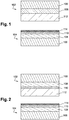
- Figure 1 shows a substrate 100 formed from steel.
- the substrate 100 is shaped so as to form a female threaded portion 102 and a male threaded portion 104.
- the male threaded portion 104 is coated with a first anti-corrosion and anti-galling layer 108.
- the first metallic layer 108 is deposited electrolytically, as described above.
- the first metallic layer 108 is constituted by a binary zinc-nickel (Zn-Ni) alloy and contains zinc (Zn), namely in a mean amount of 85.7%.
- the first metallic layer 108 has a mean thickness of 8.3 ⁇ m. Furthermore, the first metallic layer has a monophase gamma type microstructure.
- the first metallic layer 108 is coated with a passivation layer 110, as described above.
- the passivation layer has anti-corrosive properties.
- the passivation layer 110 is coated with a barrier layer 114 as described above, which also has anti-corrosive properties.
- the female threaded portion 102 is coated with a second metallic anti-galling layer 106.
- the second metallic layer 106 is constituted by a binary Zn-Ni alloy.
- the second metallic layer 106 is deposited electrolytically.
- the second metallic layer 106 contains mainly zinc (Zn) by weight. Furthermore, the second metallic layer has a monophase gamma type microstructure.
- the second metallic layer 106 is coated with a lubricant layer 112.
- the lubricant layer 112 is of the hot-melt type, having both lubricating properties and anti-corrosive properties.
- the hot-melt lubricant layer has the following composition by weight:
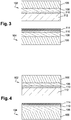
- Figure 2 shows a substrate 100 formed from steel.
- the substrate 100 is shaped so as to form a female threaded portion 102 and a male threaded portion 104.
- the male threaded portion 104 is coated with a metallic anti-corrosion and anti-galling layer 108.
- the metallic layer 108 is deposited electrolytically, as described above.
- the metallic layer 108 is constituted by a binary zinc-nickel (Zn-Ni) alloy and contains zinc (Zn), namely a mean amount of 86.5%.
- the first metal layer 108 has a mean thickness of 6.7 ⁇ m.
- the metallic layer 108 of the male threaded portion 104 is coated with a passivation layer 110, as described above.
- the passivation layer has anti-corrosive properties.
- the passivation layer 110 of the male threaded portion 104 is coated with a barrier layer 114 as described above, which also has anti-corrosive properties.
- the female threaded portion 102 is coated with a metallic anti-corrosion and anti-galling layer 108.
- the metallic layer 108 is deposited electrolytically, as described above.
- the metallic layer 108 is constituted by a binary zinc-nickel (Zn-Ni) alloy and contains zinc (Zn), namely a mean amount of 86.4%.
- the metallic layer 108 has a mean thickness of 7.4 ⁇ m.
- the metallic layer 108 of the female threaded portion 102 is coated with a passivation layer 110, as described above.
- the passivation layer has anti-corrosive properties.
- the passivation layer 110 of the female threaded portion 102 is coated with a lubricant layer 112.
- the lubricant layer 112 is of the hot-melt type having both lubricating properties and anti-corrosive properties.
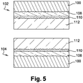
- Figure 3 shows a substrate 100 formed from steel.
- the substrate 100 is shaped so as to form a female threaded portion 102 and a male threaded portion 104.
- the male threaded portion 104 is coated with a metallic anti-corrosion and anti-galling layer 108.
- the metallic layer 108 has been deposited electrolytically, as described above.
- the metallic layer 108 is constituted by a binary zinc-nickel (Zn-Ni) alloy and contains zinc (Zn), namely a mean amount of 86.5%.
- the first metallic layer 108 has a mean thickness of 7 ⁇ m.
- the metallic layer 108 of the male threaded portion 104 is coated with a passivation layer 110, as described above.
- the passivation layer has anti-corrosive properties.
- the passivation layer 110 of the male threaded portion 104 is coated with a barrier layer 114 as described above, which also has anti-corrosive properties.
- the substrate 100 of the female threaded portion 102 has a surface roughness.
- the surface roughness has been obtained by a sand blasting process.
- a sand blasting process in particular enabled a surface roughness (Ra) in the range 1.0 ⁇ m to 10 ⁇ m to be produced. In the exemplary embodiment of Figure 3 , the surface roughness (Ra) is approximately 2 ⁇ m.
- the female threaded portion 102 is coated with a metallic anti-corrosion and anti-galling layer 108.
- the metallic layer 108 has been deposited electrolytically, as described above.
- the metallic layer 108 is constituted by a binary zinc-nickel (Zn-Ni) alloy and contains zinc (Zn), namely a mean amount of 85.6%.
- the metallic layer 108 has a mean thickness of 7 ⁇ m.
- the metallic layer 108 of the female threaded portion 102 is coated with a passivation layer 110, as described above.
- the passivation layer has anti-corrosive properties.
- the passivation layer 110 of the female threaded portion 102 is coated with a lubricant layer 112.
- the lubricant layer 112 comprises a resin and a dry solid lubricant dispersed in this resin.
- the lubricant layer 112 is constituted by a polyurethane resin (type PU2K) in which particles of carbon black have been dispersed.
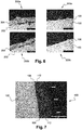
- Figure 4 shows a substrate 100 formed from steel.
- the substrate 100 is shaped so as to form a female threaded portion 102 and a male threaded portion 104.
- the male threaded portion 104 is coated with a metallic anti-corrosion and anti-galling layer 108.
- the metallic layer 108 has been deposited electrolytically, as described above.
- the metallic layer 108 is constituted by a binary zinc-nickel (Zn-Ni) alloy and contains zinc (Zn), namely a mean amount of 86.3%.
- the first metallic layer 108 has a mean thickness of 7.3 ⁇ m.
- the metallic layer 108 of the male threaded portion 104 is coated with a passivation layer 110, as described above.
- the passivation layer has anti-corrosive properties.
- the passivation layer 110 of the male threaded portion 104 is coated with a barrier layer 114 as described above, which also has anti-corrosive properties.
- the substrate 100 of the female threaded portion 102 has a surface roughness.
- the surface roughness has been obtained by a sand blasting process.
- the surface roughness (Ra) is approximately 2 ⁇ m.
- the sand blasting process may be carried out on the metallic anti-corrosion and anti-galling layer 108 of the female threaded portion 102 described below.
- the female threaded portion 102 is coated with a metallic anti-corrosion and anti-galling layer 108.
- the metallic layer 108 has been deposited electrolytically, as described above.
- the metallic layer 108 is constituted by a binary zinc-nickel (Zn-Ni) alloy and contains zinc (Zn), namely a mean amount of 86.8%.
- the metallic layer 108 has a mean thickness of 7.7 ⁇ m.
- a sand blasting process may be carried out on the metallic layer 108 of the female threaded portion 102.
- the metallic layer 108 has a surface roughness (Ra) of approximately 2 ⁇ m. This means that the passivation layer or the lubricant layer 112 described below can adhere well.
- the metallic layer 108 of the female threaded portion 102 is optionally coated with a passivation layer 110, as described above.
- the passivation layer has anti-corrosive properties.
- the passivation layer 110 of the female threaded portion 102 is coated with a lubricant layer 112.
- the lubricant layer is constituted by epoxy and MoS 2 .
- Figure 5 shows a substrate 100 formed from steel.
- the substrate 100 is shaped so as to form a female threaded portion 102 and a male threaded portion 104.
- the substrate 100 of the male threaded portion 104 has a surface roughness.
- the surface roughness has been obtained by a sand blasting process.
- the surface roughness (Ra) is approximately 2 ⁇ m.
- the sand blasting process may be carried out on the metallic anti-corrosion and anti-galling layer 108 of the female threaded portion 102 described below.
- the male threaded portion 104 is coated with a metallic anti-corrosion and anti-galling layer 108.
- the metallic layer 108 has been deposited electrolytically, as described above.
- the metallic layer 108 is constituted by a binary zinc-nickel (Zn-Ni) alloy and contains zinc (Zn), namely a mean amount of 86.7%.
- the metallic layer 108 has a mean thickness of 7.2 ⁇ m.
- a sand blasting process may be carried out on the metallic layer 108 of the male threaded portion 104.
- the metallic layer 108 has a surface roughness (Ra) of approximately 2 ⁇ m. This means that the passivation layer or the lubricant layer 112 described below can adhere well.
- the metallic layer 108 of the male threaded portion 104 is optionally coated with a passivation layer 110, as described above.
- the passivation layer has anti-corrosive properties.
- the passivation layer 110 of the male threaded portion 104 is coated with a lubricant layer 112.
- the lubricant layer 112 is constituted by acrylic resin and carbon black.
- the substrate 100 of the female threaded portion 102 has a surface roughness.
- the surface roughness has been obtained by a sand blasting process.
- the surface roughness (Ra) is approximately 2 ⁇ m.
- the sand blasting process may be carried out on the metallic anti-corrosion and anti-galling layer 108 of the female threaded portion 102 described below.
- the female threaded portion 102 is coated with a metallic anti-corrosion and anti-galling layer 108.
- the metallic layer 108 has been deposited electrolytically, as described above.
- the metallic layer 108 is constituted by a binary zinc-nickel (Zn-Ni) alloy and contains zinc (Zn), namely a mean amount of 86.2% by weight.
- the metallic layer 108 has a mean thickness of 6.7 ⁇ m.
- a sand blasting process may be carried out on the metallic layer 108 of the female threaded portion 102.
- the metallic layer 108 has a surface roughness (Ra) of approximately 2 ⁇ m. This means that the passivation layer or the lubricant layer 112 described below can adhere well.
- the metallic layer 108 of the female threaded portion 102 is optionally coated with a passivation layer 110, as described above.
- the passivation layer has anti-corrosive properties.
- the passivation layer 110 of the female threaded portion 102 is coated with a lubricant layer 112.
- the lubricant layer 112 is constituted by an acrylic resin and a dispersion of carbon black in that resin.
- the layers may extend over other elements of the threaded portion.
- the layers may extend over it.
- the Applicant has carried out comparative roughness tests between threaded portions before electrolytic deposition of a metallic layer in accordance with the invention and after electrolytic deposition of a metallic layer in accordance with the invention.
- the roughness was measured in the direction parallel to the direction of machining of said portions. The results are reported in Table 1.
- ZnNi After electrolytic deposition ZnNi Roughness Ra( ⁇ m) Rz ( ⁇ m) Rt( ⁇ m) Ra( ⁇ m) Rz( ⁇ m) Rt( ⁇ m) No sand blasting Mean 0.458 2.453 2.453 0.330 2.023 4.316 Std Dev n.a. n.a. n.a.
- Ra is the mean deviation roughness - it is the arithmetic mean of the absolute values of the distances between the peaks and valleys measured on the roughness profile.
- Rz is known as the mean maximum roughness - this is the mean of the maximum heights measured over several (for example 5) selected portions on a roughness profile.
- Rt is known as the total roughness - this is the maximum height measured over the whole of the roughness profile.
- Table 1 shows that the samples of threaded portions after electrolytic deposition have a reduced roughness in the direction parallel to the direction of machining compared with the samples of threaded portions before electrolytic deposition.
- the electrolytic deposition in accordance with the invention has a levelling effect.
- Figure 6 shows photographs of threaded elements taken with an optical microscope. More particularly, Figure 6 shows two selected portions of a prior art threaded element compared with two analogous selected portions of a threaded element in accordance with the invention.
- the microscope used was optical.
- the magnification was: x500.
- the scale indicated on each photograph is 50 ⁇ m.
- the prior art threaded element is shown in photographs 200a and 200b.
- the prior art substrate 202 formed from steel is coated with a layer 204 comprising particles of lamellar zinc dispersed in an epoxy resin.
- the layer 204 was applied using a process which is known in the art.
- the prior art process comprises pneumatic spraying of the layer 204 onto the substrate 202 at ambient temperature, followed by hot curing of the substrate/layer ensemble. During the spraying phase, the composition of the layer 204 comprises a solvent. The curing phase is used to eliminate the solvent and cross-link the layer 204.
- the photographs 200a and 200b show that the layer 204 is heterogeneous. In fact, the layer 204 of the prior art threaded element has a non-uniform microstructure.
- the threaded element of the invention is shown in photographs 300a and 300b.
- the substrate 100 is coated with a first metallic layer 108 constituted by a binary Zn-Ni alloy of the type described in Example 1 above.
- the binary alloy was applied electrolytically in order to form a homogeneous layer.
- photographs 300a and 300b of Figure 6 show that the first metallic layer 108 of the threaded element of the invention has a uniform microstructure. In the present case, it is a monophase gamma ( ⁇ ) type microstructure.
- Figure 7 shows a photograph 400 of a threaded element in accordance with the invention taken with an optical microscope.
- the magnification is: x500.
- the scale indicated on each photograph is 50 ⁇ m.
- the substrate 100 was coated with a second metallic layer 106 constituted by a binary Zn-Ni alloy of the type described in Example 1 above.
- the binary alloy was applied electrolytically in order to form a homogeneous layer.
- the metallic layer had a thickness of approximately 4 ⁇ m to approximately 6 ⁇ m (mean thickness approximately 5 ⁇ m).
- the metallic layer was coated with a lubricant layer 112 of the hot-melt HMS-3 type, as described in Example 1.
- the lubricant layer has a thickness of approximately 40 ⁇ m to approximately 43 ⁇ m.
- the second metallic layer 106 has a uniform microstructure.
- the second metallic layer constituted by a binary Zn-Ni alloy also has a monophase gamma ( ⁇ ) type microstructure.
- Figures 6 and 7 thus demonstrate that the metallic layer of the invention has a uniform microstructure.
- the elements of the tubes of the invention namely the male or female threaded portions as well as the connections produced with these portions, comply with the conditions of international standard API RP 5C5 (3rd Edition, July 2003 ).
- the tube elements resisted 15 makeup/breakout procedures and fully satisfied the sealing conditions.
- the elements of the tubes of the invention namely the male or female threaded portions as well as the connections produced with these portions, were in full compliance with the conditions of European standard NF EN ISO 9227 relating to saline mist tests.
- the tube elements responded positively as regards corrosion resistance over 1000 h of exposure to an aggressive environment.
Landscapes
- Chemical & Material Sciences (AREA)
- Engineering & Computer Science (AREA)
- Organic Chemistry (AREA)
- Chemical Kinetics & Catalysis (AREA)
- Metallurgy (AREA)
- Materials Engineering (AREA)
- Mechanical Engineering (AREA)
- Inorganic Chemistry (AREA)
- Electrochemistry (AREA)
- General Engineering & Computer Science (AREA)
- Geology (AREA)
- Life Sciences & Earth Sciences (AREA)
- Mining & Mineral Resources (AREA)
- Crystallography & Structural Chemistry (AREA)
- Oil, Petroleum & Natural Gas (AREA)
- General Chemical & Material Sciences (AREA)
- Fluid Mechanics (AREA)
- Physics & Mathematics (AREA)
- Environmental & Geological Engineering (AREA)
- Geochemistry & Mineralogy (AREA)
- General Life Sciences & Earth Sciences (AREA)
- Non-Disconnectible Joints And Screw-Threaded Joints (AREA)
- Lubricants (AREA)
- Earth Drilling (AREA)
Priority Applications (1)
| Application Number | Priority Date | Filing Date | Title |
|---|---|---|---|
| PL16722065T PL3286289T3 (pl) | 2015-04-23 | 2016-04-21 | Gwintowane połączenie rurowe wyposażone w metaliczną powłokę na gwincie i na powierzchni uszczelniającej |
Applications Claiming Priority (2)
| Application Number | Priority Date | Filing Date | Title |
|---|---|---|---|
| FR1553663A FR3035476B1 (fr) | 2015-04-23 | 2015-04-23 | Joint filete tubulaire dote d'un revetement metallique sur le filetage et la portee d'etancheite |
| PCT/EP2016/058866 WO2016170037A1 (en) | 2015-04-23 | 2016-04-21 | Threaded tubular connection provided with a metallic coating on the threading and on the sealing surface |
Publications (2)
| Publication Number | Publication Date |
|---|---|
| EP3286289A1 EP3286289A1 (en) | 2018-02-28 |
| EP3286289B1 true EP3286289B1 (en) | 2019-08-28 |
Family
ID=53404765
Family Applications (1)
| Application Number | Title | Priority Date | Filing Date |
|---|---|---|---|
| EP16722065.6A Active EP3286289B1 (en) | 2015-04-23 | 2016-04-21 | Threaded tubular connection provided with a metallic coating on the threading and on the sealing surface |
Country Status (15)
| Country | Link |
|---|---|
| US (1) | US11124733B2 (ja) |
| EP (1) | EP3286289B1 (ja) |
| JP (1) | JP6563032B2 (ja) |
| CN (1) | CN107466335B (ja) |
| AR (1) | AR104336A1 (ja) |
| AU (1) | AU2016251832B2 (ja) |
| BR (1) | BR112017017633B1 (ja) |
| CA (1) | CA2981640A1 (ja) |
| EA (1) | EA035498B1 (ja) |
| FR (1) | FR3035476B1 (ja) |
| MX (1) | MX2017013532A (ja) |
| MY (1) | MY182738A (ja) |
| PL (1) | PL3286289T3 (ja) |
| UA (1) | UA122144C2 (ja) |
| WO (1) | WO2016170037A1 (ja) |
Families Citing this family (7)
| Publication number | Priority date | Publication date | Assignee | Title |
|---|---|---|---|---|
| MX2019013679A (es) | 2017-05-22 | 2020-01-15 | Nippon Steel Corp | Conexion roscada para tuberias para la industria del petroleo y metodo para producir conexiones roscadas para tuberias para la industria del petroleo. |
| JP6964678B2 (ja) * | 2017-10-13 | 2021-11-10 | 日本製鉄株式会社 | 管用ねじ継手及び管用ねじ継手の製造方法 |
| FR3101659B1 (fr) * | 2019-10-08 | 2022-01-21 | Vallourec Oil & Gas France | Joint filete avec portee d’etancheite realisee par fabrication additive |
| CN110847826B (zh) * | 2019-10-12 | 2021-04-30 | 中国石油天然气股份有限公司 | 一种防腐套管管柱及其使用方法 |
| CN112824642A (zh) * | 2019-11-20 | 2021-05-21 | 宝山钢铁股份有限公司 | 一种高抗粘扣性能的偏梯形螺纹接头 |
| TWI735302B (zh) * | 2020-07-31 | 2021-08-01 | 林憲良 | 多重色電鍍鋅及其合金鍍層結構 |
| FR3126742B1 (fr) * | 2021-09-07 | 2024-01-19 | Vallourec Oil & Gas France | Lubrifiant solide pour ZnNi sur élément fileté tubulaire |
Family Cites Families (30)
| Publication number | Priority date | Publication date | Assignee | Title |
|---|---|---|---|---|
| US3869393A (en) * | 1970-05-21 | 1975-03-04 | Everlube Corp Of America | Solid lubricant adhesive film |
| SU896304A1 (ru) * | 1979-09-26 | 1982-01-07 | Предприятие П/Я В-8173 | Способ герметизации резьбовых соединений |
| US4468309A (en) * | 1983-04-22 | 1984-08-28 | White Engineering Corporation | Method for resisting galling |
| FR2673199B1 (fr) * | 1991-02-21 | 1994-01-21 | Vallourec Industries | Revetement de surface anti-grippage pour moyen d'assemblage de tubes par filetages et procede de realisation d'un tel revetement. |
| DE4413996C1 (de) * | 1994-04-22 | 1995-07-20 | Braas Gmbh | Dachpfanne mit einer Silikatbeschichtung |
| FR2813375B1 (fr) * | 2000-08-31 | 2003-06-20 | Vallourec Mannesmann Oil & Gas | Element filete pour joint filete tubulaire resistant au grippage |
| JP4092871B2 (ja) * | 2000-12-04 | 2008-05-28 | 住友金属工業株式会社 | ねじ継手の潤滑処理に適した潤滑被膜形成用組成物 |
| RU2258859C2 (ru) | 2001-04-11 | 2005-08-20 | Сумитомо Метал Индастриз, Лтд. | Резьбовое соединение для стальных труб (варианты) |
| RO121489B1 (ro) | 2001-04-11 | 2007-06-29 | Sumitomo Metal Industries, Ltd. | Îmbinare cu filet pentru ţevi de oţel şi procedeu pentru tratament de suprafaţă, al acesteia |
| JP3870732B2 (ja) * | 2001-07-25 | 2007-01-24 | 住友金属工業株式会社 | 耐焼付き性に優れた鋼管用ねじ継手 |
| ITRM20020512A1 (it) | 2002-10-10 | 2004-04-11 | Tenaris Connections Bv | Tubo filettato con trattamento superficiale. |
| US20040174017A1 (en) * | 2003-03-06 | 2004-09-09 | Lone Star Steel Company | Tubular goods with expandable threaded connections |
| JP4599874B2 (ja) * | 2004-04-06 | 2010-12-15 | 住友金属工業株式会社 | 油井管用ねじ継手、及びその製造方法 |
| BRPI0606637B1 (pt) * | 2005-01-13 | 2019-04-16 | Nippon Steel & Sumitomo Metal Corporation | Junta roscada para tubos de aço |
| AR052727A1 (es) | 2005-03-29 | 2007-03-28 | Sumimoto Metal Ind Ltd | Union roscada para tubos de acero y procedimiento para el tratamiento superficial de dicha union roscada |
| US7883118B2 (en) * | 2005-03-29 | 2011-02-08 | Sumitomo Metal Industries, Ltd. | Threaded joint for steel pipes |
| US7842403B2 (en) * | 2006-02-23 | 2010-11-30 | Atotech Deutschland Gmbh | Antifriction coatings, methods of producing such coatings and articles including such coatings |
| JP5028923B2 (ja) * | 2006-09-14 | 2012-09-19 | 住友金属工業株式会社 | 鋼管用ねじ継手 |
| US8322754B2 (en) * | 2006-12-01 | 2012-12-04 | Tenaris Connections Limited | Nanocomposite coatings for threaded connections |
| JP4924103B2 (ja) * | 2007-03-02 | 2012-04-25 | 住友金属工業株式会社 | 油井管用ねじ継手 |
| MX2010004780A (es) * | 2007-11-02 | 2010-11-22 | Sumitomo Metal Ind | Junta roscada para tubos con capa lubricante. |
| NO2216576T3 (ja) * | 2007-12-04 | 2018-02-17 | ||
| CN101576183B (zh) * | 2008-05-09 | 2011-02-09 | 中国石油天然气集团公司 | 双钩形螺纹联接膨胀套管接头 |
| BRPI1014102A2 (pt) * | 2009-03-31 | 2018-03-06 | Sumitomo Metal Ind | junta rosqueada para tubulações |
| US20110084477A1 (en) * | 2009-10-13 | 2011-04-14 | Hydril Company | Wedge threads with a solid lubricant coating |
| US8562771B2 (en) * | 2010-07-20 | 2013-10-22 | Tenaris Connections Limited | Joints having improved sealability, lubrication and corrosion resistance |
| UA104975C2 (uk) * | 2010-11-05 | 2014-03-25 | Ніппон Стіл Енд Сумітомо Метал Корпорейшн | Нарізне з'єднання труб, що має поліпшені характеристики при низькій температурі |
| UA105334C2 (uk) * | 2010-11-05 | 2014-04-25 | Ниппон Стил Энд Сумитомо Метал Корпорэйшн | Нарізне з'єднання труб, що має поліпшені характеристики при високому крутному моменті |
| JP5722752B2 (ja) * | 2011-11-18 | 2015-05-27 | 新日鐵住金株式会社 | 高トルク締結性能に優れた管状ねじ継手 |
| JP6047702B2 (ja) | 2013-03-27 | 2016-12-21 | 日本表面化学株式会社 | 亜鉛ニッケル合金めっき液及びめっき方法 |
-
2015
- 2015-04-23 FR FR1553663A patent/FR3035476B1/fr active Active
-
2016
- 2016-04-21 BR BR112017017633-5A patent/BR112017017633B1/pt active IP Right Grant
- 2016-04-21 US US15/565,263 patent/US11124733B2/en active Active
- 2016-04-21 MY MYPI2017703943A patent/MY182738A/en unknown
- 2016-04-21 EP EP16722065.6A patent/EP3286289B1/en active Active
- 2016-04-21 WO PCT/EP2016/058866 patent/WO2016170037A1/en active Application Filing
- 2016-04-21 CA CA2981640A patent/CA2981640A1/en not_active Abandoned
- 2016-04-21 EA EA201791915A patent/EA035498B1/ru not_active IP Right Cessation
- 2016-04-21 JP JP2017554353A patent/JP6563032B2/ja active Active
- 2016-04-21 MX MX2017013532A patent/MX2017013532A/es unknown
- 2016-04-21 UA UAA201709378A patent/UA122144C2/uk unknown
- 2016-04-21 CN CN201680015375.2A patent/CN107466335B/zh active Active
- 2016-04-21 PL PL16722065T patent/PL3286289T3/pl unknown
- 2016-04-21 AR ARP160101096A patent/AR104336A1/es active IP Right Grant
- 2016-04-21 AU AU2016251832A patent/AU2016251832B2/en active Active
Non-Patent Citations (1)
| Title |
|---|
| None * |
Also Published As
| Publication number | Publication date |
|---|---|
| CA2981640A1 (en) | 2016-10-27 |
| EA201791915A1 (ru) | 2018-01-31 |
| UA122144C2 (uk) | 2020-09-25 |
| WO2016170037A1 (en) | 2016-10-27 |
| CN107466335A (zh) | 2017-12-12 |
| FR3035476B1 (fr) | 2017-04-28 |
| BR112017017633B1 (pt) | 2021-05-04 |
| JP2018516343A (ja) | 2018-06-21 |
| AU2016251832B2 (en) | 2019-01-17 |
| EP3286289A1 (en) | 2018-02-28 |
| AR104336A1 (es) | 2017-07-12 |
| MX2017013532A (es) | 2018-02-21 |
| CN107466335B (zh) | 2020-09-01 |
| FR3035476A1 (fr) | 2016-10-28 |
| AU2016251832A1 (en) | 2017-09-14 |
| US20180171261A1 (en) | 2018-06-21 |
| JP6563032B2 (ja) | 2019-08-21 |
| PL3286289T3 (pl) | 2020-04-30 |
| US11124733B2 (en) | 2021-09-21 |
| EA035498B1 (ru) | 2020-06-25 |
| BR112017017633A2 (pt) | 2018-05-08 |
| MY182738A (en) | 2021-02-04 |
Similar Documents
| Publication | Publication Date | Title |
|---|---|---|
| EP3286288B1 (en) | Threaded tubular element provided with a metallic anti-galling coating and a lubricant layer | |
| EP3286287B1 (en) | Threaded tubular element provided with a metallic anti-corrosion and anti-galling coating | |
| EP3286289B1 (en) | Threaded tubular connection provided with a metallic coating on the threading and on the sealing surface | |
| OA18451A (en) | Threaded tubular element provided with a metallic anti-galling coating and lubricant layer | |
| OA18452A (en) | Threaded tubular connection provided with a metallic coating on the threating and on the sealing surface | |
| OA18450A (en) | Threaded tubular element provided with a metallic anti-corrosion and anti- galling coating |
Legal Events
| Date | Code | Title | Description |
|---|---|---|---|
| STAA | Information on the status of an ep patent application or granted ep patent |
Free format text: STATUS: THE INTERNATIONAL PUBLICATION HAS BEEN MADE |
|
| PUAI | Public reference made under article 153(3) epc to a published international application that has entered the european phase |
Free format text: ORIGINAL CODE: 0009012 |
|
| STAA | Information on the status of an ep patent application or granted ep patent |
Free format text: STATUS: REQUEST FOR EXAMINATION WAS MADE |
|
| 17P | Request for examination filed |
Effective date: 20171013 |
|
| AK | Designated contracting states |
Kind code of ref document: A1 Designated state(s): AL AT BE BG CH CY CZ DE DK EE ES FI FR GB GR HR HU IE IS IT LI LT LU LV MC MK MT NL NO PL PT RO RS SE SI SK SM TR |
|
| AX | Request for extension of the european patent |
Extension state: BA ME |
|
| DAV | Request for validation of the european patent (deleted) | ||
| DAX | Request for extension of the european patent (deleted) | ||
| GRAP | Despatch of communication of intention to grant a patent |
Free format text: ORIGINAL CODE: EPIDOSNIGR1 |
|
| STAA | Information on the status of an ep patent application or granted ep patent |
Free format text: STATUS: GRANT OF PATENT IS INTENDED |
|
| RIC1 | Information provided on ipc code assigned before grant |
Ipc: C10N 50/08 20060101ALI20190222BHEP Ipc: C23C 28/00 20060101ALI20190222BHEP Ipc: C25D 3/56 20060101ALI20190222BHEP Ipc: C10N 10/02 20060101ALI20190222BHEP Ipc: C25D 7/00 20060101ALI20190222BHEP Ipc: F16L 57/00 20060101ALI20190222BHEP Ipc: F16L 58/08 20060101ALI20190222BHEP Ipc: C10N 70/00 20060101ALI20190222BHEP Ipc: C10N 10/12 20060101ALI20190222BHEP Ipc: E21B 17/042 20060101ALI20190222BHEP Ipc: C10N 40/34 20060101ALI20190222BHEP Ipc: C25D 5/12 20060101ALI20190222BHEP Ipc: C10N 10/16 20060101ALI20190222BHEP Ipc: C10M 171/00 20060101AFI20190222BHEP Ipc: C10N 10/04 20060101ALI20190222BHEP Ipc: C10N 80/00 20060101ALI20190222BHEP |
|
| INTG | Intention to grant announced |
Effective date: 20190320 |
|
| RAP1 | Party data changed (applicant data changed or rights of an application transferred) |
Owner name: NIPPON STEEL CORPORATION Owner name: VALLOUREC OIL AND GAS FRANCE |
|
| GRAS | Grant fee paid |
Free format text: ORIGINAL CODE: EPIDOSNIGR3 |
|
| GRAA | (expected) grant |
Free format text: ORIGINAL CODE: 0009210 |
|
| STAA | Information on the status of an ep patent application or granted ep patent |
Free format text: STATUS: THE PATENT HAS BEEN GRANTED |
|
| AK | Designated contracting states |
Kind code of ref document: B1 Designated state(s): AL AT BE BG CH CY CZ DE DK EE ES FI FR GB GR HR HU IE IS IT LI LT LU LV MC MK MT NL NO PL PT RO RS SE SI SK SM TR |
|
| REG | Reference to a national code |
Ref country code: GB Ref legal event code: FG4D |
|
| REG | Reference to a national code |
Ref country code: CH Ref legal event code: EP |
|
| REG | Reference to a national code |
Ref country code: AT Ref legal event code: REF Ref document number: 1172403 Country of ref document: AT Kind code of ref document: T Effective date: 20190915 |
|
| REG | Reference to a national code |
Ref country code: IE Ref legal event code: FG4D |
|
| REG | Reference to a national code |
Ref country code: DE Ref legal event code: R096 Ref document number: 602016019396 Country of ref document: DE |
|
| REG | Reference to a national code |
Ref country code: NL Ref legal event code: FP |
|
| REG | Reference to a national code |
Ref country code: RO Ref legal event code: EPE |
|
| REG | Reference to a national code |
Ref country code: NO Ref legal event code: T2 Effective date: 20190828 |
|
| REG | Reference to a national code |
Ref country code: LT Ref legal event code: MG4D |
|
| PG25 | Lapsed in a contracting state [announced via postgrant information from national office to epo] |
Ref country code: LT Free format text: LAPSE BECAUSE OF FAILURE TO SUBMIT A TRANSLATION OF THE DESCRIPTION OR TO PAY THE FEE WITHIN THE PRESCRIBED TIME-LIMIT Effective date: 20190828 Ref country code: BG Free format text: LAPSE BECAUSE OF FAILURE TO SUBMIT A TRANSLATION OF THE DESCRIPTION OR TO PAY THE FEE WITHIN THE PRESCRIBED TIME-LIMIT Effective date: 20191128 Ref country code: SE Free format text: LAPSE BECAUSE OF FAILURE TO SUBMIT A TRANSLATION OF THE DESCRIPTION OR TO PAY THE FEE WITHIN THE PRESCRIBED TIME-LIMIT Effective date: 20190828 Ref country code: HR Free format text: LAPSE BECAUSE OF FAILURE TO SUBMIT A TRANSLATION OF THE DESCRIPTION OR TO PAY THE FEE WITHIN THE PRESCRIBED TIME-LIMIT Effective date: 20190828 Ref country code: PT Free format text: LAPSE BECAUSE OF FAILURE TO SUBMIT A TRANSLATION OF THE DESCRIPTION OR TO PAY THE FEE WITHIN THE PRESCRIBED TIME-LIMIT Effective date: 20191230 Ref country code: FI Free format text: LAPSE BECAUSE OF FAILURE TO SUBMIT A TRANSLATION OF THE DESCRIPTION OR TO PAY THE FEE WITHIN THE PRESCRIBED TIME-LIMIT Effective date: 20190828 |
|
| PG25 | Lapsed in a contracting state [announced via postgrant information from national office to epo] |
Ref country code: IS Free format text: LAPSE BECAUSE OF FAILURE TO SUBMIT A TRANSLATION OF THE DESCRIPTION OR TO PAY THE FEE WITHIN THE PRESCRIBED TIME-LIMIT Effective date: 20191228 Ref country code: ES Free format text: LAPSE BECAUSE OF FAILURE TO SUBMIT A TRANSLATION OF THE DESCRIPTION OR TO PAY THE FEE WITHIN THE PRESCRIBED TIME-LIMIT Effective date: 20190828 Ref country code: RS Free format text: LAPSE BECAUSE OF FAILURE TO SUBMIT A TRANSLATION OF THE DESCRIPTION OR TO PAY THE FEE WITHIN THE PRESCRIBED TIME-LIMIT Effective date: 20190828 Ref country code: GR Free format text: LAPSE BECAUSE OF FAILURE TO SUBMIT A TRANSLATION OF THE DESCRIPTION OR TO PAY THE FEE WITHIN THE PRESCRIBED TIME-LIMIT Effective date: 20191129 Ref country code: AL Free format text: LAPSE BECAUSE OF FAILURE TO SUBMIT A TRANSLATION OF THE DESCRIPTION OR TO PAY THE FEE WITHIN THE PRESCRIBED TIME-LIMIT Effective date: 20190828 Ref country code: LV Free format text: LAPSE BECAUSE OF FAILURE TO SUBMIT A TRANSLATION OF THE DESCRIPTION OR TO PAY THE FEE WITHIN THE PRESCRIBED TIME-LIMIT Effective date: 20190828 |
|
| PG25 | Lapsed in a contracting state [announced via postgrant information from national office to epo] |
Ref country code: TR Free format text: LAPSE BECAUSE OF FAILURE TO SUBMIT A TRANSLATION OF THE DESCRIPTION OR TO PAY THE FEE WITHIN THE PRESCRIBED TIME-LIMIT Effective date: 20190828 |
|
| PG25 | Lapsed in a contracting state [announced via postgrant information from national office to epo] |
Ref country code: DK Free format text: LAPSE BECAUSE OF FAILURE TO SUBMIT A TRANSLATION OF THE DESCRIPTION OR TO PAY THE FEE WITHIN THE PRESCRIBED TIME-LIMIT Effective date: 20190828 Ref country code: EE Free format text: LAPSE BECAUSE OF FAILURE TO SUBMIT A TRANSLATION OF THE DESCRIPTION OR TO PAY THE FEE WITHIN THE PRESCRIBED TIME-LIMIT Effective date: 20190828 |
|
| PG25 | Lapsed in a contracting state [announced via postgrant information from national office to epo] |
Ref country code: SK Free format text: LAPSE BECAUSE OF FAILURE TO SUBMIT A TRANSLATION OF THE DESCRIPTION OR TO PAY THE FEE WITHIN THE PRESCRIBED TIME-LIMIT Effective date: 20190828 Ref country code: IS Free format text: LAPSE BECAUSE OF FAILURE TO SUBMIT A TRANSLATION OF THE DESCRIPTION OR TO PAY THE FEE WITHIN THE PRESCRIBED TIME-LIMIT Effective date: 20200224 Ref country code: SM Free format text: LAPSE BECAUSE OF FAILURE TO SUBMIT A TRANSLATION OF THE DESCRIPTION OR TO PAY THE FEE WITHIN THE PRESCRIBED TIME-LIMIT Effective date: 20190828 |
|
| REG | Reference to a national code |
Ref country code: DE Ref legal event code: R097 Ref document number: 602016019396 Country of ref document: DE |
|
| PLBE | No opposition filed within time limit |
Free format text: ORIGINAL CODE: 0009261 |
|
| STAA | Information on the status of an ep patent application or granted ep patent |
Free format text: STATUS: NO OPPOSITION FILED WITHIN TIME LIMIT |
|
| PG2D | Information on lapse in contracting state deleted |
Ref country code: IS |
|
| 26N | No opposition filed |
Effective date: 20200603 |
|
| PG25 | Lapsed in a contracting state [announced via postgrant information from national office to epo] |
Ref country code: SI Free format text: LAPSE BECAUSE OF FAILURE TO SUBMIT A TRANSLATION OF THE DESCRIPTION OR TO PAY THE FEE WITHIN THE PRESCRIBED TIME-LIMIT Effective date: 20190828 |
|
| PG25 | Lapsed in a contracting state [announced via postgrant information from national office to epo] |
Ref country code: MC Free format text: LAPSE BECAUSE OF FAILURE TO SUBMIT A TRANSLATION OF THE DESCRIPTION OR TO PAY THE FEE WITHIN THE PRESCRIBED TIME-LIMIT Effective date: 20190828 |
|
| REG | Reference to a national code |
Ref country code: CH Ref legal event code: PL |
|
| PG25 | Lapsed in a contracting state [announced via postgrant information from national office to epo] |
Ref country code: CH Free format text: LAPSE BECAUSE OF NON-PAYMENT OF DUE FEES Effective date: 20200430 Ref country code: LI Free format text: LAPSE BECAUSE OF NON-PAYMENT OF DUE FEES Effective date: 20200430 Ref country code: LU Free format text: LAPSE BECAUSE OF NON-PAYMENT OF DUE FEES Effective date: 20200421 |
|
| REG | Reference to a national code |
Ref country code: BE Ref legal event code: MM Effective date: 20200430 |
|
| PG25 | Lapsed in a contracting state [announced via postgrant information from national office to epo] |
Ref country code: BE Free format text: LAPSE BECAUSE OF NON-PAYMENT OF DUE FEES Effective date: 20200430 |
|
| PG25 | Lapsed in a contracting state [announced via postgrant information from national office to epo] |
Ref country code: IE Free format text: LAPSE BECAUSE OF NON-PAYMENT OF DUE FEES Effective date: 20200421 |
|
| PG25 | Lapsed in a contracting state [announced via postgrant information from national office to epo] |
Ref country code: MT Free format text: LAPSE BECAUSE OF FAILURE TO SUBMIT A TRANSLATION OF THE DESCRIPTION OR TO PAY THE FEE WITHIN THE PRESCRIBED TIME-LIMIT Effective date: 20190828 Ref country code: CY Free format text: LAPSE BECAUSE OF FAILURE TO SUBMIT A TRANSLATION OF THE DESCRIPTION OR TO PAY THE FEE WITHIN THE PRESCRIBED TIME-LIMIT Effective date: 20190828 |
|
| PG25 | Lapsed in a contracting state [announced via postgrant information from national office to epo] |
Ref country code: MK Free format text: LAPSE BECAUSE OF FAILURE TO SUBMIT A TRANSLATION OF THE DESCRIPTION OR TO PAY THE FEE WITHIN THE PRESCRIBED TIME-LIMIT Effective date: 20190828 |
|
| PGFP | Annual fee paid to national office [announced via postgrant information from national office to epo] |
Ref country code: NO Payment date: 20230322 Year of fee payment: 8 Ref country code: FR Payment date: 20230321 Year of fee payment: 8 |
|
| PGFP | Annual fee paid to national office [announced via postgrant information from national office to epo] |
Ref country code: PL Payment date: 20230321 Year of fee payment: 8 Ref country code: IT Payment date: 20230322 Year of fee payment: 8 |
|
| PGFP | Annual fee paid to national office [announced via postgrant information from national office to epo] |
Ref country code: RO Payment date: 20230419 Year of fee payment: 8 Ref country code: DE Payment date: 20230321 Year of fee payment: 8 |
|
| PGFP | Annual fee paid to national office [announced via postgrant information from national office to epo] |
Ref country code: AT Payment date: 20230322 Year of fee payment: 8 |
|
| PGFP | Annual fee paid to national office [announced via postgrant information from national office to epo] |
Ref country code: NL Payment date: 20240320 Year of fee payment: 9 |
|
| PGFP | Annual fee paid to national office [announced via postgrant information from national office to epo] |
Ref country code: CZ Payment date: 20240326 Year of fee payment: 9 Ref country code: GB Payment date: 20240320 Year of fee payment: 9 |