EP3285618B1 - Support cushions with active ventilation - Google Patents
Support cushions with active ventilation Download PDFInfo
- Publication number
- EP3285618B1 EP3285618B1 EP15890095.1A EP15890095A EP3285618B1 EP 3285618 B1 EP3285618 B1 EP 3285618B1 EP 15890095 A EP15890095 A EP 15890095A EP 3285618 B1 EP3285618 B1 EP 3285618B1
- Authority
- EP
- European Patent Office
- Prior art keywords
- layer
- base layer
- body supporting
- supporting layer
- lower base
- Prior art date
- Legal status (The legal status is an assumption and is not a legal conclusion. Google has not performed a legal analysis and makes no representation as to the accuracy of the status listed.)
- Active
Links
- 238000009423 ventilation Methods 0.000 title description 3
- 239000006260 foam Substances 0.000 claims description 111
- 239000000463 material Substances 0.000 claims description 18
- 238000004891 communication Methods 0.000 claims description 14
- 239000012530 fluid Substances 0.000 claims description 12
- 125000006850 spacer group Chemical group 0.000 claims description 7
- 239000004753 textile Substances 0.000 claims description 7
- 239000004744 fabric Substances 0.000 claims description 5
- RNFJDJUURJAICM-UHFFFAOYSA-N 2,2,4,4,6,6-hexaphenoxy-1,3,5-triaza-2$l^{5},4$l^{5},6$l^{5}-triphosphacyclohexa-1,3,5-triene Chemical compound N=1P(OC=2C=CC=CC=2)(OC=2C=CC=CC=2)=NP(OC=2C=CC=CC=2)(OC=2C=CC=CC=2)=NP=1(OC=1C=CC=CC=1)OC1=CC=CC=C1 RNFJDJUURJAICM-UHFFFAOYSA-N 0.000 claims description 4
- 239000003063 flame retardant Substances 0.000 claims description 4
- 239000011148 porous material Substances 0.000 claims description 3
- 239000002131 composite material Substances 0.000 claims description 2
- 230000000712 assembly Effects 0.000 description 43
- 238000000429 assembly Methods 0.000 description 43
- 238000000034 method Methods 0.000 description 11
- 230000007958 sleep Effects 0.000 description 8
- 208000010340 Sleep Deprivation Diseases 0.000 description 7
- 238000013461 design Methods 0.000 description 4
- 230000004044 response Effects 0.000 description 4
- 230000000284 resting effect Effects 0.000 description 4
- 239000000853 adhesive Substances 0.000 description 3
- 230000001070 adhesive effect Effects 0.000 description 3
- 238000001816 cooling Methods 0.000 description 3
- 230000037361 pathway Effects 0.000 description 3
- 230000004913 activation Effects 0.000 description 2
- 230000008901 benefit Effects 0.000 description 2
- 230000006835 compression Effects 0.000 description 2
- 238000007906 compression Methods 0.000 description 2
- 230000006870 function Effects 0.000 description 2
- -1 polypropylene Polymers 0.000 description 2
- 238000011160 research Methods 0.000 description 2
- 239000000758 substrate Substances 0.000 description 2
- XLYOFNOQVPJJNP-UHFFFAOYSA-N water Substances O XLYOFNOQVPJJNP-UHFFFAOYSA-N 0.000 description 2
- 229920000742 Cotton Polymers 0.000 description 1
- 206010020772 Hypertension Diseases 0.000 description 1
- 206010049976 Impatience Diseases 0.000 description 1
- 206010022998 Irritability Diseases 0.000 description 1
- 229920000079 Memory foam Polymers 0.000 description 1
- 206010028980 Neoplasm Diseases 0.000 description 1
- 239000004698 Polyethylene Substances 0.000 description 1
- 239000004743 Polypropylene Substances 0.000 description 1
- 239000004793 Polystyrene Substances 0.000 description 1
- 229920005830 Polyurethane Foam Polymers 0.000 description 1
- 229920001247 Reticulated foam Polymers 0.000 description 1
- 230000003213 activating effect Effects 0.000 description 1
- 238000004026 adhesive bonding Methods 0.000 description 1
- 230000036528 appetite Effects 0.000 description 1
- 235000019789 appetite Nutrition 0.000 description 1
- 230000009286 beneficial effect Effects 0.000 description 1
- 230000015572 biosynthetic process Effects 0.000 description 1
- DQXBYHZEEUGOBF-UHFFFAOYSA-N but-3-enoic acid;ethene Chemical compound C=C.OC(=O)CC=C DQXBYHZEEUGOBF-UHFFFAOYSA-N 0.000 description 1
- 201000011510 cancer Diseases 0.000 description 1
- 150000001720 carbohydrates Chemical class 0.000 description 1
- 235000014633 carbohydrates Nutrition 0.000 description 1
- 230000001413 cellular effect Effects 0.000 description 1
- 230000001684 chronic effect Effects 0.000 description 1
- 230000006378 damage Effects 0.000 description 1
- 201000010099 disease Diseases 0.000 description 1
- 208000037265 diseases, disorders, signs and symptoms Diseases 0.000 description 1
- 239000006185 dispersion Substances 0.000 description 1
- 230000000694 effects Effects 0.000 description 1
- 230000002996 emotional effect Effects 0.000 description 1
- 239000005038 ethylene vinyl acetate Substances 0.000 description 1
- 229920001821 foam rubber Polymers 0.000 description 1
- 230000036541 health Effects 0.000 description 1
- 238000010438 heat treatment Methods 0.000 description 1
- 239000005556 hormone Substances 0.000 description 1
- 229940088597 hormone Drugs 0.000 description 1
- 230000036737 immune function Effects 0.000 description 1
- 208000022119 inability to concentrate Diseases 0.000 description 1
- 230000002452 interceptive effect Effects 0.000 description 1
- 230000001788 irregular Effects 0.000 description 1
- 238000004519 manufacturing process Methods 0.000 description 1
- 239000008210 memory foam Substances 0.000 description 1
- 230000003340 mental effect Effects 0.000 description 1
- 238000012986 modification Methods 0.000 description 1
- 230000004048 modification Effects 0.000 description 1
- 230000008520 organization Effects 0.000 description 1
- 229920001200 poly(ethylene-vinyl acetate) Polymers 0.000 description 1
- 229920000728 polyester Polymers 0.000 description 1
- 229920000573 polyethylene Polymers 0.000 description 1
- 229920000642 polymer Polymers 0.000 description 1
- 229920001155 polypropylene Polymers 0.000 description 1
- 229920002223 polystyrene Polymers 0.000 description 1
- 229920002635 polyurethane Polymers 0.000 description 1
- 239000004814 polyurethane Substances 0.000 description 1
- 239000011496 polyurethane foam Substances 0.000 description 1
- 230000008569 process Effects 0.000 description 1
- 230000036385 rapid eye movement (rem) sleep Effects 0.000 description 1
- 208000019116 sleep disease Diseases 0.000 description 1
- 239000002438 stress hormone Substances 0.000 description 1
- 239000000126 substance Substances 0.000 description 1
- 230000001629 suppression Effects 0.000 description 1
- 239000000725 suspension Substances 0.000 description 1
- 239000003190 viscoelastic substance Substances 0.000 description 1
- 230000004584 weight gain Effects 0.000 description 1
- 235000019786 weight gain Nutrition 0.000 description 1
Images



Classifications
-
- A—HUMAN NECESSITIES
- A47—FURNITURE; DOMESTIC ARTICLES OR APPLIANCES; COFFEE MILLS; SPICE MILLS; SUCTION CLEANERS IN GENERAL
- A47C—CHAIRS; SOFAS; BEDS
- A47C21/00—Attachments for beds, e.g. sheet holders or bed-cover holders; Ventilating, cooling or heating means in connection with bedsteads or mattresses
- A47C21/04—Devices for ventilating, cooling or heating
- A47C21/042—Devices for ventilating, cooling or heating for ventilating or cooling
- A47C21/044—Devices for ventilating, cooling or heating for ventilating or cooling with active means, e.g. by using air blowers or liquid pumps
-
- A—HUMAN NECESSITIES
- A47—FURNITURE; DOMESTIC ARTICLES OR APPLIANCES; COFFEE MILLS; SPICE MILLS; SUCTION CLEANERS IN GENERAL
- A47C—CHAIRS; SOFAS; BEDS
- A47C27/00—Spring, stuffed or fluid mattresses or cushions specially adapted for chairs, beds or sofas
- A47C27/14—Spring, stuffed or fluid mattresses or cushions specially adapted for chairs, beds or sofas with foamed material inlays
- A47C27/15—Spring, stuffed or fluid mattresses or cushions specially adapted for chairs, beds or sofas with foamed material inlays consisting of two or more layers
Definitions
- the present invention relates to a support cushion according to the preamble part of claim 1.
- a support cushion is known from JP 2005 192883 A .
- sleep deprivation can have significant negative impacts on longevity, productivity, and overall mental, emotional, and physical health.
- Chronic sleep debt has been linked to weight gain and, more specifically, has been observed to not only affect the way the body processes and stores carbohydrates, but has also been observed to alter hormone levels that affect appetite.
- sleep debt may result in irritability, impatience, inability to concentrate, and moodiness, which has led some researchers to suggest a link between sleep debt and worksite accidents, traffic incidents, and general afternoon inattentiveness.
- the present invention relates to support cushions as claimed in claim 1.
- the present invention relates to support cushions, such as mattress assemblies, that make use of a fan located within the support cushion to draw and amount of air through and away from the support cushion.
- the support cushions of the present invention allow a user to increase his or her level of comfort, including sleep comfort, by actively ventilating the support cushions.
- a support cushion in the form of a mattress assembly includes a body supporting layer having a first surface and a second surface.
- the body supporting layer of the mattress assembly includes a first porous foam insert that is positioned in a first side of the body supporting layer, and a second porous foam insert that is positioned in a second side of the body supporting layer opposite the first porous foam insert.
- Both the first porous foam insert and the second porous foam insert are generally sized to support a torso of a user lying on the mattress assembly.
- the first porous foam insert and the second porous foam insert are not only configured to support the torso of a user lying on the mattress assembly, but are also configured to assist in dissipating any heat generated by the torso of a user lying on the mattress assembly away from the body supporting layer and the remainder of the mattress assembly.
- the body supporting layer of the mattress assembly is covered by a comfort portion or layer that is positioned atop the body supporting layer.
- the comfort layer defines a first plurality of channels and a second plurality of channels that extend through the comfort layer and that are positioned over the first porous foam insert and the second porous foam insert, respectively, of the body supporting layer.
- the channels of the comfort layer place the first porous foam insert and the second porous foam insert in fluid communication with not only the comfort layer, but also with the environment surrounding the mattress assembly and/or the body of a user lying on the mattress assembly.
- the comfort layer also functions to provide a level of comfort to a body of a user or a portion of thereof that is resting on the mattress assembly.
- an upper base layer that is positioned adjacent to the second surface of the body supporting layer.
- the upper base layer defines a first plurality of air conduits and a second plurality of air conduits that extend through the upper base layer and that are positioned below the first porous foam insert and the second porous foam insert, respectively, of the body supporting layer.
- a lower base layer is also included in the exemplary mattress assembly and is positioned adjacent to the upper base layer opposite the body supporting layer.
- the lower base layer defines a first cavity and a second cavity, which both extend through the lower base layer.
- the first cavity of the lower base layer houses a fan assembly and is positioned below and is in fluid communication with the first plurality of air conduits in the upper base layer .
- the second cavity houses a separate fan assembly and is positioned below and is in fluid communication with the second plurality of air conduits .
- the fan assemblies draw air through the channels in the comfort layer, through the porous foam inserts in the body supporting layer, through air conduits in the upper base layer, and then through the fan assemblies and the lower base layer, where it is then exhausted air into a bottom layer of the mattress assembly that is positioned adjacent to the lower base layer opposite the upper base layer.
- each of the fan assemblies includes a fan that is mounted in a housing sized to fit within one of the cavities defined by the lower base layer and to be frictionally held in position within the cavities even when the mattress assembly is moved, tipped, or otherwise adjusted.
- the fan assemblies each further include a sleeve that is positioned between each of the housings and the respective cavities and that is comprised of a material which promotes friction between the cavities and the respective housings.
- an exemplary mattress assembly also includes a power supply for supplying electrical current to the fan assemblies and a controller for controlling the electrical current supplied to the fan assemblies from the power supply.
- an exemplary mattress assembly can further include several features that are operably connected to the body supporting layer and provide input to the controller.
- an exemplary mattress assembly includes temperature sensors that are operably connected to porous foam inserts included in the body supporting layer and that provide temperature feedback to the controller to thereby not only allow the controller to selectively provide power to the fan assemblies and adjust how quickly or how much air is moved through the mattress assembly in response to the received temperature feedback, but to also maintain a desired temperature at the first surface of the body supporting layer.
- pressure sensors are also operably connected to the body supporting layer and provide pressure feedback to the controller in response to a user resting upon or adjacent to the first surface of the body supporting layer.
- a method for actively ventilating a support cushion includes first providing a support of the present invention. Power, in the form of electrical current, is then supplied to the fans in the support cushion, such that the fan draws air from the first surface of the body supporting layer, through upper base layer and lower base layer, and into the bottom layer and away from the body supporting layer of the support cushion to thereby actively ventilate the support cushion and dissipate any heat away from the body supporting layer of the support cushion.
- the present invention relates to support cushions.
- the present invention relates to support cushions, such as mattress assemblies, that make use of a fan located within the support cushion to draw an amount of air through and away from the support cushion.
- the support cushions of the present invention allow a user to increase his or her level of comfort, including sleep comfort, by actively ventilating the support cushions.
- a support cushion in the form of a mattress assembly 10 is provided that includes a body supporting layer 20 having a first surface 22, which is generally an upper surface of the body supporting layer 20, and a second surface 24, which is opposite the first surface 22 and is generally the lower surface of the body supporting layer 20.
- the body supporting layer 20 of the mattress assembly 10 includes a first porous foam insert 26a positioned in a first side 28 of the body supporting layer 20, and a second porous foam insert 26b that is positioned in a second side 29 of the body supporting layer 20 opposite the first porous foam insert 26a.
- Both the first porous foam insert 26a and the second porous foam insert 26b are generally sized to support a torso of a user lying on the mattress assembly 10.
- the first porous foam insert 26a and the second porous foam insert 26b are not only configured to support the torso of a user lying on the mattress assembly 10, but the first porous foam insert 26a and the second porous foam insert 26b are also configured to assist in dissipating any heat generated by the torso of a user lying on the mattress assembly 10 away from the body supporting layer 20 and the remainder of the mattress assembly 10, as described in further detail below.
- the body supporting layer 20 of the mattress assembly 10 is generally comprised of a continuous layer of flexible foam for suitably distributing pressure from a user's body or portion thereof across the body supporting layer 20.
- flexible foams include, but are not limited to, latex foam, reticulated or non-reticulated visco-elastic foam (sometimes referred to as memory foam or low-resilience foam), reticulated or non-reticulated non-visco-elastic foam, polyurethane high-resilience foam.
- expanded polymer foams e.g., expanded ethylene vinyl acetate, polypropylene, polystyrene, or polyethylene
- the body supporting layer 20 is comprised of a visco-elastic foam that has a low resilience as well as a sufficient density and hardness, which allows pressure to be absorbed uniformly and distributed evenly across the body supporting layer 20 of the mattress assembly 10.
- a visco-elastic foam that has a low resilience as well as a sufficient density and hardness, which allows pressure to be absorbed uniformly and distributed evenly across the body supporting layer 20 of the mattress assembly 10.
- such visco-elastic foams have a hardness of at least about 10 N to no greater than about 80 N, as measured by exerting pressure from a plate against a sample of the material to a compression of at least 40% of an original thickness of the material at approximately room temperature (i.e., 21°C to 23°C), where the 40% compression is held for a set period of time as established by the International Organization of Standardization (ISO) 2439 hardness measuring standard.
- ISO International Organization of Standardization
- the visco-elastic foam has a hardness of about 10 N, about 20 N, about 30 N, about 40 N, about 50 N, about 60 N, about 70 N, or about 80 N to provide a desired degree of comfort and body-conforming qualities.
- the visco-elastic foam described herein for use in the mattress assembly 10 can also have a density that assists in providing a desired degree of comfort and body-conforming qualities, as well as an increased degree of material durability.
- the density of the visco-elastic foam used in the body supporting layer 20 has a density of no less than about 30 kg/m 3 to no greater than about 150 kg/m 3 .
- the density of the visco-elastic foam used in the body supporting layer 20 of the mattress assembly 10 is about 30 kg/m 3 , about 40 kg/m 3 , about 50 kg/m 3 , about 60 kg/m 3 , about 70 kg/m 3 , about 80 kg/m 3 , about 90 kg/m 3 , about 100 kg/m 3 , about 110 kg/m 3 , about 120 kg/m 3 , about 130 kg/m 3 , about 140 kg/m 3 , or about 150 kg/m 3 .
- a visco-elastic foam having a particular density will affect other characteristics of the foam, including its hardness, the manner in which the foam responds to pressure, and the overall feel of the foam, but it is appreciated that a visco-elastic foam having a desired density and hardness can readily be selected for a particular application or mattress assembly as desired. Additionally, it is appreciated that the body supporting layers of the mattress assemblies need not be comprised of a continuous layer of flexible foam at all, but can also take the form of more traditional mattresses, including spring-based mattresses.
- the porous foam inserts 26a, 26b are also comprised of a visco-elastic foam, but are generally comprised of a viscoelastic foam having a porosity greater than the visco-elastic foam included in the body supporting layer 20 to allow air to enter the porous foam inserts 26a, 26b more readily than the remainder of the body supporting layer 20.
- porous foam inserts 26a, 26b need not be comprised of a visco-elastic foam at all, but that any number of porous flexible foams can be used to produce a porous foam insert having a porosity sufficient to allow for air to readily enter and move through.
- porous foam or “porous flexible foam” (visco-elastic or otherwise) is used herein to generally refer to flexible foam having a cellular foam structure in which at least a portion of the cells of the foam are essentially skeletal.
- the cells of the foam are each defined by a plurality of apertured windows surrounded by cell struts, where the cell windows of the porous foam can be entirely absent (leaving only the cell struts) or substantially missing.
- the foam is considered “porous” if at least 50% of the windows of the cells are missing (i.e., windows having apertures therethrough, or windows that are completely missing and therefore leaving only the cell struts).
- Such structures can be created by destruction or other removal of cell window material, by chemical or mechanical means, or by preventing the complete formation of cell windows during the manufacturing process of the foam.
- the term “porous” can thus be used interchangeably with the term “reticulated” when referring to flexible foam.
- the body supporting layer 20 of the mattress assembly 10 is further covered by a comfort portion or layer 62 that is positioned atop the body supporting layer 20.
- the comfort layer 62 defines a first plurality of channels 66a and a second plurality of channels 66b that extend through the comfort layer 62 and that are positioned over the first porous foam insert 26a and the second porous foam insert 26b, respectively.
- the channels 66a, 66b of the comfort layer 62 place the first porous foam insert 26a and the second porous foam insert 26b in fluid communication with not only the comfort layer 62, but also with the environment surrounding the mattress assembly 10 and/or the body of a user lying on the mattress assembly 10.
- the comfort layer 62 also functions to provide a level of comfort to a body of a user or a portion of thereof that is resting on the mattress assembly 10.
- the comfort layer 62 can also be comprised of a visco-clastic foam, but typically has a density, hardness, or both that is less than that of the body supporting layer 20 of the mattress assembly 10 such that the comfort layer 62 provides a softer surface on which to rest the body of a user.
- the mattress assembly 10 includes a body supporting layer 20 that is comprised of visco-elastic foam with a density of about 80 kg/m 3 and a hardness of about 13 N, while the comfort layer is comprised of a visco-elastic foam with a density of about 35 kg/m 3 and a hardness of about 10 N.
- the porous foam inserts 26a, 26b, and the comfort layer 62 further included in the mattress assembly 10 is an upper base layer 30 that is positioned adjacent to the second surface 24 of the body supporting layer 20.
- the upper base layer 30 defines a first plurality of air conduits 32a and a second plurality of air conduits 32b that extend through the upper base layer 30 and that are positioned below the first porous foam insert 26a and the second porous foam insert 26b, respectively, of the body supporting layer 20.
- the first plurality of air conduits 32a and the second plurality of air conduits 32b are thus placed in direct fluid communication with the first porous foam insert 26a and the second porous foam insert 26b, and create a pathway for air to flow from the body supporting layer 20 and through the upper base layer 30, the importance of which is also described in further detail below.
- pathways for air to flow from the body supporting layer 20 and through the upper base layer 30 can also be created by using a variety of other means, such as porous foam inserts with or without air conduits and which may be positioned in an exemplary upper base layer.
- a lower base layer 40 is also included in the exemplary mattress assembly 10 and is positioned adjacent to the upper base layer 30 opposite the body supporting layer 20.
- the lower base layer 40 defines a first cavity 42a and a second cavity 42b, which both extend through the lower base layer 40.
- the first cavity 42a of the lower base layer 40 houses a fan assembly 80a and is positioned below and is in fluid communication with the first plurality of air conduits 32a in the upper base layer 30.
- the second cavity 42b houses a separate fan assembly 80b and is positioned below and is in fluid communication with the second plurality of air conduits 32b.
- the fan assemblies 80a, 80b draw air through the channels 66a, 66b in the comfort layer 62, through the porous foam inserts 26a, 26b in the body supporting layer 20. through air conduits 32a, 32b in the upper base layer 30, and then through the fan assemblies 80a, 80b and the lower base layer 40, where it is then exhausted air into a bottom layer 50 of the mattress assembly 10 that is positioned adjacent to the lower base layer 40 opposite the upper base layer 30.
- any associated heat around or within the comfort layer 62 and the body supporting layer 20 that may be present as a result of a user lying on the mattress assembly 10 is drawn away from the comfort layer 62 and the body supporting layer 20 and is pulled through the mattress assembly 10 before being dissipated away from the mattress assembly 10 through the bottom layer 50.
- the upper base layer 30 and the lower base layer 40 of the mattress assembly can also be comprised of a flexible foam. including any of the flexible foams described above with reference to the body supporting layer 20.
- the flexible foam comprising the body supporting layer 20 typically has a density less than that of the upper base layer 30 and the lower base layer 40, such that the upper base layer 30 and the lower base layer 40 have a density and hardness sufficient for supporting the body supporting layer 20 and the comfort layer 62 of the mattress assembly.
- the upper base layer 30 and the lower base layer 40 are comprised of a higher density, porous polyurethane foam that provides sufficient support to the overlying body supporting layer 20 and the comfort layer, but that also provides an open environment in which air can move by virtue of its porous structure.
- the bottom layer 50 is further comprised of a breathable porous material that promotes the dispersion of the air. including the air exhausted into the bottom layer 50 by the fan assemblies 80a, 80b, but that also provides support to the remainder of the mattress assembly 10.
- the porous materials included in the bottom layer 50 can be selected from a reticulated foam. knitted spacer fabric, textile, or a composite material.
- a knitted spacer fabric can be included that is generally comprised of two exterior mesh textile substrates and an insert material such as polyester monofilaments which are configured to keep the two exterior mesh textile substrates separated.
- Such knitted spacer fabrics include, by way of example, the WellcoolTM 3D spacer fabric manufactured by Quanzhou Wellcool Cushion Technology Co., Ltd (Fujian, China).
- the bottom layer 50 as well as the comfort layer 62, the body supporting layer 20, the upper base layer 30, and the lower base layer 40 are generally secured to one another to prevent the body supporting layer 20, the upper base layer 30, the lower base layer 40, the bottom layer 50, and the comfort layer 62 from moving relative to one another during use.
- Various means of securing one layer of material to another can be used in this regard, including tape, hook and loop fasteners, conventional fasteners, stitches, and the like.
- the body supporting layer 20, the upper base layer 30, the lower base layer 40, the bottom layer 50, and the comfort layer 62 are bonded together by an adhesive or cohesive bonding material to create a substantially continuous assembly where the body supporting layer 20, the upper base layer 30, the lower base layer 40, the bottom layer 50, and the comfort layer 62 are fully adhered to one another.
- adhesive bonding materials include, for example, environmentally-friendly, water based adhesives. like SABA AQUABOND RSD, a two-component water-based adhesive product produced by SABA DINXPERLO BV. B-7090 AA, Dinxperlo, Belgium.
- the fan assemblies 80a, 80b included in the mattress assembly 10 are housed internally within the mattress assembly 10. More specifically, the fan assemblies 80a, 80b are housed within the cavities 42a, 42b of the lower base layer 40 with the upper base layer 30 covering the fan assemblies from above and the bottom layer 50 covering the fan assemblies 80a, 80b from below.
- each of the fan assemblies 80a, 80b includes a fan 82a, 82b that is mounted in a housing 84a, 84b sized to fit within one of the cavities 42a, 42b defined by the lower base layer 40 and to be frictionally held in position within the cavities 42a, 42b even when the mattress assembly 10 is moved, tipped, or otherwise adjusted.
- the fan assemblies 80a, 80b each further include a sleeve 88a, 88b that is positioned between each of the housings 84a, 84b and the respective cavities 42a, 42b and that is comprised of a material which promotes friction between the cavities 42a, 42b and the respective housings 84a, 84b, for example a textile.
- the sleeves 88a, 88b can also be comprised of a flame retardant material to provide a layer of fire suppression between the fan assemblies 80a, 80b and the rest of the mattress assembly 10.
- each of the sleeves 88a, 88b provide a means of securing and positioning an air filter 86a, 86b within each of the fan assemblies 80a, 80b.
- the mattress assembly 10 also includes a power supply 92 for supplying electrical current to the fan assemblies 80a, 80b and a controller 90 for controlling the electrical current supplied to the fan assemblies 80a, 80b from the power supply 92.
- the controller 90 By including the controller 90 in the mattress assembly 10, the amount of electrical current supplied to the fan assemblies 80a, 80b from the power supply 92 can be controlled to allow for a desired amount of air to move through the mattress assembly 10 and, consequently, a desired amount of heat to be dissipated away from the body supporting layer 20 of the mattress assembly 10.
- the controller 90 can be used to simply turn the fan assemblies 80a, 80b on or off depending on whether the user wishes to ventilate the mattress assembly 10 and remove heat from the body supporting layer 20 of the mattress assembly 10, or can be used to operate the fan assemblies 80a, 80b at a particular speed depending on how quickly the user wishes to ventilate the mattress assembly 10 and remove heat from the body supporting layer 20 of the mattress assembly 10.
- the controller 90 can also be configured to automatically control the electrical current supplied to the fan assemblies 80a, 80b from the power supply 92, such that the electrical current can be supplied to the fan assemblies 80a, 80b when the first surface 22 of the body supporting layer 20 reaches a desired temperature.
- the controller 90 can be configured to allow the electrical current to be supplied to the fan assemblies 80a.
- a predetermined time period such as for an 8-hour sleeping period or for a length of time a user usually spends in a specific stage of the sleep cycle (e.g.. REM sleep) in order to increase the sleep comfort of a user.
- a specific stage of the sleep cycle e.g.. REM sleep
- the mattress assembly 10 also includes several features that are operably connected to the body supporting layer 20 and provide input to the controller 90.
- the mattress assembly 10 includes temperature sensors 94a, 94b that are operably connected to porous foam inserts 26a, 26b included in the body supporting layer 20 and that provide temperature feedback to the controller 90 to thereby not only allow the controller 90 to selectively provide power to the fan assemblies 80a, 80b and adjust how quickly or how much air is moved through the mattress assembly 10 in response to the received temperature feedback, but to also maintain a desired temperature at the first surface 22 of the body supporting layer 20.
- FIG. 2 As another example, and as also shown best in FIG. 2 .
- pressure sensors 96a, 96b are also operably connected to the body supporting layer 20 and provide pressure feedback to the controller 90 in response to a user resting upon or adjacent to the first surface 22 of the body supporting layer 20, such that the controller 90 can automatically allow power to be provided to the fan assemblies 80a, 80b air to be moved through the mattress assembly 10 as soon as the user lies on the mattress assembly 10 or otherwise places an amount of pressure on the mattress assembly 10.
- An additional benefit of the inclusion of the pressure sensors 96a, 96b is that the controller 90 can be configured to automatically shut off the fan assemblies 80a, 80b if a user is no longer lying on the mattress assembly 10.
- a remote control not shown
- FIG. 5 in another exemplary embodiment of the present invention, another support cushion in the form of a mattress assembly 110 is provided that includes additional features to increase the comfort and convenience of the user of the mattress assembly 110.
- a support cushion in the form of a mattress assembly 110 is provided that includes additional features to increase the comfort and convenience of the user of the mattress assembly 110.
- FIGS. 5 Like the support cushion shown in FIGS.
- the mattress assembly 110 also includes: a comfort layer 162 defining a plurality of channels 166; a body supporting layer 120 including a porous foam insert 126; an upper base layer 130 positioned below the body supporting layer 120 and defining a plurality of air conduits 132 in fluid communication with the porous foam insert 126; a lower base layer 140 defining a cavity 142 with a fan assembly 180 located within the cavity 142; and a bottom layer 150 positioned below the lower base layer 140.
- an adjustable foundation 170 is included in the mattress assembly, however, is an adjustable foundation 170 that is positioned below the bottom layer 150 and allows a user to place the mattress assembly 110 into one or more desired ergonomic positions.
- a cover 172 is included in the mattress assembly 110 and surrounds the comfort layer 162, the body supporting layer 120, the upper base layer 130, the lower base layer 140, and the bottom layer 150 of the mattress assembly 110.
- the cover 172 in the form of a fire sock that surround the various layers is comprised of a flame retardant material.
- an exemplary cover of the present invention can also be comprised of another textile, such as cotton that provide an exemplary support cushion with a unitary appearance, but that also provides a user with a sufficiently soft surface on which to rest while being sufficiently breathable to allow air to be drawn through the cover and the exemplary support cushion.
- another textile such as cotton that provide an exemplary support cushion with a unitary appearance, but that also provides a user with a sufficiently soft surface on which to rest while being sufficiently breathable to allow air to be drawn through the cover and the exemplary support cushion.
- the support cushions shown in FIGS. 1-3 and 5 are in the form of mattress assemblies 10, 110 and are dimensionally-sized to support a user lying in a supine or prone position, it is contemplated that the features described herein are equally applicable to other support cushions, such as head pillows, seat cushions, seat backs, neck pillows, leg spacer pillows, mattress topers, overlays, and the like.
- the phrase "body support” or “body supporting” is used herein to refer to any and all such objects having any size or shape, and that are capable of supporting, or are generally used to support, the body of a user or a portion thereof.
- 1-3 includes two removable inserts 26a, 26b, two sets of air conduits 32a, 32b, two cavities 42a, 42b, and two fan assemblies 80a, 80b, it is also contemplated other embodiments may include any number of removable portions, conduits, cavities, and fan assemblies depending on the size and shape of the particular support cushion.
- a method for actively ventilating a support cushion includes first providing a support cushion having: a body supporting layer having a first surface and a second surface opposite the first surface; an upper base layer positioned adjacent to the second surface of the body supporting layer and defining one or more air conduits extending through the upper base layer and in fluid communication with the body supporting layer; a lower base layer positioned adjacent to the upper base layer opposite the body supporting layer and defining a cavity extending through the lower base layer; a bottom layer positioned adjacent to the lower base layer opposite the upper base layer; and a fan located within the cavity define by the lower base layer.
- Power in the form of electrical current, is then supplied to the fan, such that the fan draws air from the first surface of the body supporting layer, through upper base layer and lower base layer, and into the bottom layer and away from the body supporting layer of the support cushion to thereby actively ventilate the support cushion and dissipate any heat away from the body supporting layer of the support cushion.
Landscapes
- Mattresses And Other Support Structures For Chairs And Beds (AREA)
Description
- The present invention relates to a support cushion according to the preamble part of claim 1. Such a support cushion is known from
JP 2005 192883 A - An aspect of successful and restful sleep is individual sleep comfort. Medical research suggests that sleep deprivation ("sleep debt") can have significant negative impacts on longevity, productivity, and overall mental, emotional, and physical health. Chronic sleep debt has been linked to weight gain and, more specifically, has been observed to not only affect the way the body processes and stores carbohydrates, but has also been observed to alter hormone levels that affect appetite. Moreover, sleep debt may result in irritability, impatience, inability to concentrate, and moodiness, which has led some researchers to suggest a link between sleep debt and worksite accidents, traffic incidents, and general afternoon inattentiveness. Furthermore, sleep disorders have been linked to hypertension, increased stress hormone levels, and irregular heartbeat, and additional research has recently suggested that a lack of sleep can affect immune function, resulting in increased susceptibility to illness and disease, e.g., cancer. In all, researchers have now suggested that sleep debt costs the United States $63 billion annually in lost productivity due to these various effects. Accordingly, a support cushion that improves sleep comfort and lowers individual sleep debt would be both highly desirable and beneficial.
- The present invention relates to support cushions as claimed in claim 1. In particular, the present invention relates to support cushions, such as mattress assemblies, that make use of a fan located within the support cushion to draw and amount of air through and away from the support cushion. Thus, the support cushions of the present invention allow a user to increase his or her level of comfort, including sleep comfort, by actively ventilating the support cushions.
- In one exemplary embodiment of the present invention, a support cushion in the form of a mattress assembly is provided that includes a body supporting layer having a first surface and a second surface. The body supporting layer of the mattress assembly includes a first porous foam insert that is positioned in a first side of the body supporting layer, and a second porous foam insert that is positioned in a second side of the body supporting layer opposite the first porous foam insert. Both the first porous foam insert and the second porous foam insert are generally sized to support a torso of a user lying on the mattress assembly. Thus, as a result of the size and position of the first porous foam insert and the second porous foam insert, the first porous foam insert and the second porous foam insert are not only configured to support the torso of a user lying on the mattress assembly, but are also configured to assist in dissipating any heat generated by the torso of a user lying on the mattress assembly away from the body supporting layer and the remainder of the mattress assembly.
- The body supporting layer of the mattress assembly is covered by a comfort portion or layer that is positioned atop the body supporting layer. The comfort layer defines a first plurality of channels and a second plurality of channels that extend through the comfort layer and that are positioned over the first porous foam insert and the second porous foam insert, respectively, of the body supporting layer. By positioning the channels over the first porous foam insert and the second porous foam insert, the channels of the comfort layer place the first porous foam insert and the second porous foam insert in fluid communication with not only the comfort layer, but also with the environment surrounding the mattress assembly and/or the body of a user lying on the mattress assembly. In addition to placing the first porous foam insert and the second porous foam insert in communication with the surrounding environment, however, the comfort layer also functions to provide a level of comfort to a body of a user or a portion of thereof that is resting on the mattress assembly.
- Further included in the mattress assembly is an upper base layer that is positioned adjacent to the second surface of the body supporting layer. The upper base layer defines a first plurality of air conduits and a second plurality of air conduits that extend through the upper base layer and that are positioned below the first porous foam insert and the second porous foam insert, respectively, of the body supporting layer. By positioning the first plurality of air conduits and the second plurality of air conduits below the first porous foam insert and the second porous foam insert of the body supporting layer, the first plurality of air conduits and the second plurality of air conduits are thus placed in direct fluid communication with the first porous foam insert and the second porous foam insert, and create a pathway for air to flow from the body supporting layer and through the upper base layer.
- In addition to the upper base layer, a lower base layer is also included in the exemplary mattress assembly and is positioned adjacent to the upper base layer opposite the body supporting layer. The lower base layer defines a first cavity and a second cavity, which both extend through the lower base layer. The first cavity of the lower base layer houses a fan assembly and is positioned below and is in fluid communication with the first plurality of air conduits in the upper base layer . Similarly, the second cavity houses a separate fan assembly and is positioned below and is in fluid communication with the second plurality of air conduits . In this regard, upon activation of the fan assemblies in the first cavity and the second cavity defined by the lower base layer, the fan assemblies draw air through the channels in the comfort layer, through the porous foam inserts in the body supporting layer, through air conduits in the upper base layer, and then through the fan assemblies and the lower base layer, where it is then exhausted air into a bottom layer of the mattress assembly that is positioned adjacent to the lower base layer opposite the upper base layer.
- With further respect to the fan assemblies included in the mattress assembly, as indicated above, the fan assemblies are housed within the cavities of the lower base layer with the upper base layer covering the fan assemblies from above and the bottom layer covering the fan assemblies from below. In this regard, each of the fan assemblies includes a fan that is mounted in a housing sized to fit within one of the cavities defined by the lower base layer and to be frictionally held in position within the cavities even when the mattress assembly is moved, tipped, or otherwise adjusted. To further promote the frictional connection between the housings and the cavities defined by the lower base layer, the fan assemblies each further include a sleeve that is positioned between each of the housings and the respective cavities and that is comprised of a material which promotes friction between the cavities and the respective housings.
- To provide an amount of control over the amount of air being moved by the fan and the active ventilation of the mattress assembly, an exemplary mattress assembly also includes a power supply for supplying electrical current to the fan assemblies and a controller for controlling the electrical current supplied to the fan assemblies from the power supply. To provide an additional level of control over the movement of air through the mattress, an exemplary mattress assembly can further include several features that are operably connected to the body supporting layer and provide input to the controller. For example, in some embodiments, an exemplary mattress assembly includes temperature sensors that are operably connected to porous foam inserts included in the body supporting layer and that provide temperature feedback to the controller to thereby not only allow the controller to selectively provide power to the fan assemblies and adjust how quickly or how much air is moved through the mattress assembly in response to the received temperature feedback, but to also maintain a desired temperature at the first surface of the body supporting layer. As another example, in some embodiments, pressure sensors are also operably connected to the body supporting layer and provide pressure feedback to the controller in response to a user resting upon or adjacent to the first surface of the body supporting layer.
- Each of the exemplary support cushions described herein can also be used as part of a method for actively ventilating a support cushion. In some implementations, a method for actively ventilating a support cushion includes first providing a support of the present invention. Power, in the form of electrical current, is then supplied to the fans in the support cushion, such that the fan draws air from the first surface of the body supporting layer, through upper base layer and lower base layer, and into the bottom layer and away from the body supporting layer of the support cushion to thereby actively ventilate the support cushion and dissipate any heat away from the body supporting layer of the support cushion.
- Further features and advantages of the present invention will become evident to those of ordinary skill in the art after a study of the description, figures, and non-limiting examples in this document.
-
-
FIG. 1 is a perspective view of an exemplary support cushion, in the form of a mattress assembly, made in accordance with the present invention; -
FIG. 2 is an exploded, perspective view of the exemplary mattress assembly ofFIG. 1 ; -
FIG. 3 is a cross-sectional view of the exemplary mattress assembly ofFIG. 1 taken along line 3-3 ofFIG. 1 ; -
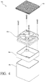
FIG. 4 is an exploded perspective view of a fan assembly included in the exemplary mattress assembly ofFIG. 1 ; and -
FIG. 5 is a cross-sectional view of another exemplary support cushion, in the form of another mattress assembly, made in accordance with the present invention and showing the mattress assembly having an adjustable foundation. - The present invention relates to support cushions. In particular, the present invention relates to support cushions, such as mattress assemblies, that make use of a fan located within the support cushion to draw an amount of air through and away from the support cushion. Thus, the support cushions of the present invention allow a user to increase his or her level of comfort, including sleep comfort, by actively ventilating the support cushions.
- Referring first to
FIGS. 1-3 , in one exemplary embodiment of the present invention, a support cushion in the form of amattress assembly 10 is provided that includes abody supporting layer 20 having afirst surface 22, which is generally an upper surface of thebody supporting layer 20, and asecond surface 24, which is opposite thefirst surface 22 and is generally the lower surface of thebody supporting layer 20. Thebody supporting layer 20 of themattress assembly 10 includes a firstporous foam insert 26a positioned in afirst side 28 of thebody supporting layer 20, and a secondporous foam insert 26b that is positioned in asecond side 29 of thebody supporting layer 20 opposite the firstporous foam insert 26a. Both the first porous foam insert 26a and the secondporous foam insert 26b are generally sized to support a torso of a user lying on themattress assembly 10. Thus, as a result of the size and position of the firstporous foam insert 26a and the secondporous foam insert 26b, the firstporous foam insert 26a and the secondporous foam insert 26b are not only configured to support the torso of a user lying on themattress assembly 10, but the firstporous foam insert 26a and the secondporous foam insert 26b are also configured to assist in dissipating any heat generated by the torso of a user lying on themattress assembly 10 away from thebody supporting layer 20 and the remainder of themattress assembly 10, as described in further detail below. - The
body supporting layer 20 of themattress assembly 10 is generally comprised of a continuous layer of flexible foam for suitably distributing pressure from a user's body or portion thereof across thebody supporting layer 20. Such flexible foams include, but are not limited to, latex foam, reticulated or non-reticulated visco-elastic foam (sometimes referred to as memory foam or low-resilience foam), reticulated or non-reticulated non-visco-elastic foam, polyurethane high-resilience foam. expanded polymer foams (e.g., expanded ethylene vinyl acetate, polypropylene, polystyrene, or polyethylene), and the like. In the embodiment shown inFIGS. 1-4 , thebody supporting layer 20 is comprised of a visco-elastic foam that has a low resilience as well as a sufficient density and hardness, which allows pressure to be absorbed uniformly and distributed evenly across thebody supporting layer 20 of themattress assembly 10. Generally, such visco-elastic foams have a hardness of at least about 10 N to no greater than about 80 N, as measured by exerting pressure from a plate against a sample of the material to a compression of at least 40% of an original thickness of the material at approximately room temperature (i.e., 21°C to 23°C), where the 40% compression is held for a set period of time as established by the International Organization of Standardization (ISO) 2439 hardness measuring standard. In some embodiments, the visco-elastic foam has a hardness of about 10 N, about 20 N, about 30 N, about 40 N, about 50 N, about 60 N, about 70 N, or about 80 N to provide a desired degree of comfort and body-conforming qualities. - The visco-elastic foam described herein for use in the
mattress assembly 10 can also have a density that assists in providing a desired degree of comfort and body-conforming qualities, as well as an increased degree of material durability. In some embodiments, the density of the visco-elastic foam used in thebody supporting layer 20 has a density of no less than about 30 kg/m3 to no greater than about 150 kg/m3. In some embodiments, the density of the visco-elastic foam used in thebody supporting layer 20 of themattress assembly 10 is about 30 kg/m3, about 40 kg/m3, about 50 kg/m3, about 60 kg/m3, about 70 kg/m3, about 80 kg/m3, about 90 kg/m3, about 100 kg/m3, about 110 kg/m3, about 120 kg/m3, about 130 kg/m3, about 140 kg/m3, or about 150 kg/m3. Of course, the selection of a visco-elastic foam having a particular density will affect other characteristics of the foam, including its hardness, the manner in which the foam responds to pressure, and the overall feel of the foam, but it is appreciated that a visco-elastic foam having a desired density and hardness can readily be selected for a particular application or mattress assembly as desired. Additionally, it is appreciated that the body supporting layers of the mattress assemblies need not be comprised of a continuous layer of flexible foam at all, but can also take the form of more traditional mattresses, including spring-based mattresses. - With even further respect to the
body supporting layer 20 of themattress assembly 10 and, in particular, theporous foam inserts body supporting layer 20 of themattress assembly 10, theporous foam inserts body supporting layer 20 to allow air to enter theporous foam inserts body supporting layer 20. Of course, it is also contemplated that theporous foam inserts - Referring still to
FIGS. 1-3 , thebody supporting layer 20 of themattress assembly 10 is further covered by a comfort portion orlayer 62 that is positioned atop thebody supporting layer 20. Thecomfort layer 62 defines a first plurality ofchannels 66a and a second plurality ofchannels 66b that extend through thecomfort layer 62 and that are positioned over the firstporous foam insert 26a and the secondporous foam insert 26b, respectively. By positioning thechannels porous foam insert 26a and the secondporous foam insert 26b, thechannels comfort layer 62 place the firstporous foam insert 26a and the secondporous foam insert 26b in fluid communication with not only thecomfort layer 62, but also with the environment surrounding themattress assembly 10 and/or the body of a user lying on themattress assembly 10. In addition to placing the firstporous foam insert 26a and the secondporous foam insert 26b in communication with the surrounding environment, however, thecomfort layer 62 also functions to provide a level of comfort to a body of a user or a portion of thereof that is resting on themattress assembly 10. In this regard, thecomfort layer 62 can also be comprised of a visco-clastic foam, but typically has a density, hardness, or both that is less than that of thebody supporting layer 20 of themattress assembly 10 such that thecomfort layer 62 provides a softer surface on which to rest the body of a user. For example, in certain embodiments, themattress assembly 10 includes abody supporting layer 20 that is comprised of visco-elastic foam with a density of about 80 kg/m3 and a hardness of about 13 N, while the comfort layer is comprised of a visco-elastic foam with a density of about 35 kg/m3 and a hardness of about 10 N. - Regardless of the particular types of foam included in the
body supporting layer 20, theporous foam inserts comfort layer 62. further included in themattress assembly 10 is anupper base layer 30 that is positioned adjacent to thesecond surface 24 of thebody supporting layer 20. Theupper base layer 30 defines a first plurality ofair conduits 32a and a second plurality ofair conduits 32b that extend through theupper base layer 30 and that are positioned below the firstporous foam insert 26a and the secondporous foam insert 26b, respectively, of thebody supporting layer 20. By positioning the first plurality ofair conduits 32a and the second plurality ofair conduits 32b below the firstporous foam insert 26a and the secondporous foam insert 26b of thebody supporting layer 20, the first plurality ofair conduits 32a and the second plurality ofair conduits 32b are thus placed in direct fluid communication with the firstporous foam insert 26b and the secondporous foam insert 26b, and create a pathway for air to flow from thebody supporting layer 20 and through theupper base layer 30, the importance of which is also described in further detail below. Of course, pathways for air to flow from thebody supporting layer 20 and through theupper base layer 30 can also be created by using a variety of other means, such as porous foam inserts with or without air conduits and which may be positioned in an exemplary upper base layer. - In addition to the
upper base layer 30, and referring still toFIGS. 1-3 , alower base layer 40 is also included in theexemplary mattress assembly 10 and is positioned adjacent to theupper base layer 30 opposite thebody supporting layer 20. Thelower base layer 40 defines afirst cavity 42a and asecond cavity 42b, which both extend through thelower base layer 40. Thefirst cavity 42a of thelower base layer 40 houses afan assembly 80a and is positioned below and is in fluid communication with the first plurality ofair conduits 32a in theupper base layer 30. Similarly, thesecond cavity 42b houses aseparate fan assembly 80b and is positioned below and is in fluid communication with the second plurality ofair conduits 32b. In this regard, upon activation of thefan assemblies first cavity 42a and thesecond cavity 42b defined by thelower base layer 40, thefan assemblies channels comfort layer 62, through theporous foam inserts body supporting layer 20. throughair conduits upper base layer 30, and then through thefan assemblies lower base layer 40, where it is then exhausted air into abottom layer 50 of themattress assembly 10 that is positioned adjacent to thelower base layer 40 opposite theupper base layer 30. In other words, by activating thefan assemblies comfort layer 62 and thebody supporting layer 20 that may be present as a result of a user lying on themattress assembly 10 is drawn away from thecomfort layer 62 and thebody supporting layer 20 and is pulled through themattress assembly 10 before being dissipated away from themattress assembly 10 through thebottom layer 50. - With further regard to the
upper base layer 30 and thelower base layer 40 of themattress assembly 10, like thebody supporting layer 20 and thecomfort layer 62, theupper base layer 30 and thelower base layer 40 can also be comprised of a flexible foam. including any of the flexible foams described above with reference to thebody supporting layer 20. The flexible foam comprising thebody supporting layer 20, however, typically has a density less than that of theupper base layer 30 and thelower base layer 40, such that theupper base layer 30 and thelower base layer 40 have a density and hardness sufficient for supporting thebody supporting layer 20 and thecomfort layer 62 of the mattress assembly. For example, in themattress assembly 10 shown inFIGS. 1-3 , theupper base layer 30 and thelower base layer 40 are comprised of a higher density, porous polyurethane foam that provides sufficient support to the overlyingbody supporting layer 20 and the comfort layer, but that also provides an open environment in which air can move by virtue of its porous structure. - Similar to the
upper base layer 30 and thelower base layer 40. thebottom layer 50 is further comprised of a breathable porous material that promotes the dispersion of the air. including the air exhausted into thebottom layer 50 by thefan assemblies mattress assembly 10. In some embodiments. the porous materials included in thebottom layer 50 can be selected from a reticulated foam. knitted spacer fabric, textile, or a composite material. For instance, in some embodiments, it is contemplated that a knitted spacer fabric can be included that is generally comprised of two exterior mesh textile substrates and an insert material such as polyester monofilaments which are configured to keep the two exterior mesh textile substrates separated. Such knitted spacer fabrics include, by way of example, the Wellcool™ 3D spacer fabric manufactured by Quanzhou Wellcool Cushion Technology Co., Ltd (Fujian, China). - Regardless of the particular materials used in the
bottom layer 50, in themattress assembly 10, thebottom layer 50 as well as thecomfort layer 62, thebody supporting layer 20, theupper base layer 30, and thelower base layer 40 are generally secured to one another to prevent thebody supporting layer 20, theupper base layer 30, thelower base layer 40, thebottom layer 50, and thecomfort layer 62 from moving relative to one another during use. Various means of securing one layer of material to another can be used in this regard, including tape, hook and loop fasteners, conventional fasteners, stitches, and the like. In one particular embodiment, thebody supporting layer 20, theupper base layer 30, thelower base layer 40, thebottom layer 50, and thecomfort layer 62 are bonded together by an adhesive or cohesive bonding material to create a substantially continuous assembly where thebody supporting layer 20, theupper base layer 30, thelower base layer 40, thebottom layer 50, and thecomfort layer 62 are fully adhered to one another. Such adhesive bonding materials include, for example, environmentally-friendly, water based adhesives. like SABA AQUABOND RSD, a two-component water-based adhesive product produced by SABA DINXPERLO BV. B-7090 AA, Dinxperlo, Belgium. - Turning now to the
fan assemblies mattress assembly 10, as indicated above and referring now toFIGS. 1-4 , the fan assemblies are housed internally within themattress assembly 10. More specifically, thefan assemblies cavities lower base layer 40 with theupper base layer 30 covering the fan assemblies from above and thebottom layer 50 covering thefan assemblies fan assemblies fan housing cavities lower base layer 40 and to be frictionally held in position within thecavities mattress assembly 10 is moved, tipped, or otherwise adjusted. To further promote the frictional connection between thehousings cavities lower base layer 40, thefan assemblies sleeve housings respective cavities cavities respective housings sleeves fan assemblies mattress assembly 10. Furthermore, each of thesleeves air filter fan assemblies - Referring again to
FIGS. 1-3 , to provide an amount of control over the amount of air being moved by the fan and the active ventilation of themattress assembly 10, themattress assembly 10 also includes apower supply 92 for supplying electrical current to thefan assemblies controller 90 for controlling the electrical current supplied to thefan assemblies power supply 92. By including thecontroller 90 in themattress assembly 10, the amount of electrical current supplied to thefan assemblies power supply 92 can be controlled to allow for a desired amount of air to move through themattress assembly 10 and, consequently, a desired amount of heat to be dissipated away from thebody supporting layer 20 of themattress assembly 10. For example, thecontroller 90 can be used to simply turn thefan assemblies mattress assembly 10 and remove heat from thebody supporting layer 20 of themattress assembly 10, or can be used to operate thefan assemblies mattress assembly 10 and remove heat from thebody supporting layer 20 of themattress assembly 10. Alternatively, thecontroller 90 can also be configured to automatically control the electrical current supplied to thefan assemblies power supply 92, such that the electrical current can be supplied to thefan assemblies first surface 22 of thebody supporting layer 20 reaches a desired temperature. As another example, thecontroller 90 can be configured to allow the electrical current to be supplied to thefan assemblies 80a. 80b from thepower supply 92 for a predetermined time period, such as for an 8-hour sleeping period or for a length of time a user usually spends in a specific stage of the sleep cycle (e.g.. REM sleep) in order to increase the sleep comfort of a user. - To provide an additional level of control over the movement of air through the
mattress assembly 10, themattress assembly 10 also includes several features that are operably connected to thebody supporting layer 20 and provide input to thecontroller 90. For example, as shown best inFIG. 2 , themattress assembly 10 includestemperature sensors porous foam inserts body supporting layer 20 and that provide temperature feedback to thecontroller 90 to thereby not only allow thecontroller 90 to selectively provide power to thefan assemblies mattress assembly 10 in response to the received temperature feedback, but to also maintain a desired temperature at thefirst surface 22 of thebody supporting layer 20. As another example, and as also shown best inFIG. 2 .pressure sensors body supporting layer 20 and provide pressure feedback to thecontroller 90 in response to a user resting upon or adjacent to thefirst surface 22 of thebody supporting layer 20, such that thecontroller 90 can automatically allow power to be provided to thefan assemblies mattress assembly 10 as soon as the user lies on themattress assembly 10 or otherwise places an amount of pressure on themattress assembly 10. An additional benefit of the inclusion of thepressure sensors controller 90 can be configured to automatically shut off thefan assemblies mattress assembly 10. Of course, such desired temperature or pressure feedback settings can be directed, inputted or adjusted at thecontroller 90 itself, or in certain embodiments of the present invention, can be transmitted to thecontroller 90 from a remote control (not shown) that is also operably connected to thecontroller 90. - As a refinement to the support cushions of the present invention, and referring now to
FIG. 5 , in another exemplary embodiment of the present invention, another support cushion in the form of amattress assembly 110 is provided that includes additional features to increase the comfort and convenience of the user of themattress assembly 110. Like the support cushion shown inFIGS. 1-4 , themattress assembly 110 also includes: a comfort layer 162 defining a plurality ofchannels 166; abody supporting layer 120 including aporous foam insert 126; anupper base layer 130 positioned below thebody supporting layer 120 and defining a plurality ofair conduits 132 in fluid communication with theporous foam insert 126; a lower base layer 140 defining acavity 142 with afan assembly 180 located within thecavity 142; and abottom layer 150 positioned below the lower base layer 140. Further included in the mattress assembly, however, is anadjustable foundation 170 that is positioned below thebottom layer 150 and allows a user to place themattress assembly 110 into one or more desired ergonomic positions. - As a further refinement to the support cushions of the present invention, various covers can also be included and used to cover various portions of the support cushions. For example and referring still to
FIG. 5 , acover 172 is included in themattress assembly 110 and surrounds the comfort layer 162, thebody supporting layer 120, theupper base layer 130, the lower base layer 140, and thebottom layer 150 of themattress assembly 110. In themattress assembly 110, thecover 172 in the form of a fire sock that surround the various layers is comprised of a flame retardant material. It is also contemplated, however, that an exemplary cover of the present invention can also be comprised of another textile, such as cotton that provide an exemplary support cushion with a unitary appearance, but that also provides a user with a sufficiently soft surface on which to rest while being sufficiently breathable to allow air to be drawn through the cover and the exemplary support cushion. - As yet another refinement to the present invention, although the support cushions shown in
FIGS. 1-3 and5 are in the form ofmattress assemblies body supporting layer 20 of themattress assembly 10 shown inFIGS. 1-3 , includes tworemovable inserts air conduits cavities fan assemblies - Each of the exemplary support cushions described herein can also be used as part of a method for actively ventilating a support cushion. In some implementations, a method for actively ventilating a support cushion includes first providing a support cushion having: a body supporting layer having a first surface and a second surface opposite the first surface; an upper base layer positioned adjacent to the second surface of the body supporting layer and defining one or more air conduits extending through the upper base layer and in fluid communication with the body supporting layer; a lower base layer positioned adjacent to the upper base layer opposite the body supporting layer and defining a cavity extending through the lower base layer; a bottom layer positioned adjacent to the lower base layer opposite the upper base layer; and a fan located within the cavity define by the lower base layer. Power, in the form of electrical current, is then supplied to the fan, such that the fan draws air from the first surface of the body supporting layer, through upper base layer and lower base layer, and into the bottom layer and away from the body supporting layer of the support cushion to thereby actively ventilate the support cushion and dissipate any heat away from the body supporting layer of the support cushion.
- Throughout this document, various references are mentioned, including the references set forth in the following list:
-
- 1.
U.S. Patent No. 8,034,445 to Landvik, et al., issued Oct. 11, 2011 , and entitled "Laminated Visco-Elastic Support." - 2.
U.S. Patent No. 8,025.964 to Landvik, et al., issued Sept. 27. 2011 . and entitled "Laminated Visco-Elastic Support." - 3.
U.S. Patent No. 7,979,374 to Landvik, issued July 12, 2011 , and entitled "Product Demonstration System and Method for Using the Same." - 4.
U.S. Patent No. 7,735,169 to Wassilefsky, issued Jun. 15, 2010 , and entitled "Comfort Pillow." - 5.
U.S. Patent No. 7,707,670 to Fogg, issued May 4, 2010 , and entitled "Pillow top for a Cushion." - 6.
U.S. Patent No. 7,555,615 to Landvik, issued June 30. 2009 , and entitled "Product Demonstration System and Method for Using the Same." - 7.
U.S. Patent No. 7,507,468 to Landvik, et al., issued Mar. 24, 2009 , and entitled "Laminated Visco-Elastic Support." - 8.
U.S. Patent No. 7,469,437 to Mikkelsen, et al., issued Dec. 30, 2008 , and entitled "Reticulated Material Body Support and Method." - 9.
U.S. Patent No. 7,444,702 to Fogg, issued Nov. 4,2008 , and entitled "Pillow top for a Cushion." - 10.
U.S. Patent No. 7.415,742 to Wassilefsky, issued Aug. 26, 2008 , and entitled "Comfort Pillow." - 11.
U.S. Design Patent No. D558,499 to Maarbjerg, issued Jan. 1, 2008 , and entitled "Pillow." - 12.
U.S. Patent No. 7,155,765 to Fogg, issued Jan. 2, 2007 , and entitled "Pillow top for a Cushion." - 13.
U.S. Design Patent No. D529,325 to Maarbjerg, issued Oct. 3. 2006 . and entitled "Pillow." - 14. United States Patent No.
7,082,633 to Maarbjerg, issued Aug. 1, 2006 , and entitled "Pillow." - 15.
U.S. Patent No. 7,051,389 to Wassilefsky, issued May 30, 2006 , and entitled "Comfort Pillow." - 16.
U.S. Patent No. 6,866,915 to Landvik, issued Mar. 15, 2005 , and entitled "Cushion." - 17.
U.S. Patent No. 6,764,502 to Bieberich, issued Jul. 20, 2004 , and entitled "High-Efficiency Cooling Pads, Mattresses, and Sleeves." - 18.
U.S. Patent No. 6,602,579 to Landvik, issued Aug. 5, 2003 , and entitled "Cushion." - 19.
U.S. Patent No. 6,578,218 to Wassilefsky, issued Jun. 17, 2003 , and entitled "Leg Spacer Pillow." - 20.
U.S. Patent No. 6,541,094 to Landvik, et al.. issued Apr. 1, 2003 , and entitled "Laminated Visco-Elastic Support." - 21.
U.S. Patent No. 6,402,775 to Bierberich, issued June 11, 2002 , and entitled "High-Efficiency Cooling Pads, Mattresses, and Sleeves." - 22.
U.S. Patent No. 6,253,401 to Boyd, issued Jul. 3, 2001 , and entitled "Air Mattress System." - 23.
U.S. Patent No. 5,448,788 to Wu, issued Sep. 12, 1995 , and entitled "Thermoelectric Cooling-Heating Mattress." - 24.
U.S. Design Patent No. D456,660 to Landvik, issued May 7, 2002 , and entitled "Contoured Head Pillow." - 25.
U.S. Patent Application Publication No. 2011/0252562 by Mikkelsen, et al., published Oct. 20, 2011 , and entitled "Adjustable-Firmness Body Support and Method." - 26.
U.S. Patent Application Publication No. 2008/0028536 by Hadden-Cook, published Feb. 7,2008 , and entitled "Mattress with cooling airflow." - 27.
U.S. Patent Application Publication No. 2007/0094803 by Fogg, published May 3, 2007 , and entitled "Pillow top for a Cushion." - 28.
U.S. Patent Application Publication No. 2006/0288490 by Mikkelsen, et al., published Dec. 28. 2006 , and entitled "Reticulated Material Body Support and Method." - 29.
U.S. Patent Application Publication No. 2006/0277684 by Wassilefsky, published Dec. 14. 2006 , and entitled "Comfort Pillow." - 30.
U.S. Patent Application Publication No. 2006/0174414 by Maarbjerg, published Aug. 10, 2006 , and entitled "Pillow." - 31. U.S. Patent Application Publication No.
US2005/0202214 by Landvik, published Sep. 15, 2005 , and entitled "Cushion." - 32.
U.S. Patent Application Publication No. 2005/0084667 by Landvik, et al., published Apr. 21, 2005 , and entitled "Laminated Visco-Elastic Support." - 33.
U.S. Patent Application Publication No. 2005/0076446 by Fogg, published Apr. 14, 2005 , and entitled "Pillow top for a Cushion." - 34.
U.S. Patent Application Publication No. 2004/0073931 by Trussel Jr., et al., published Apr. 15, 2004 , and entitled "Interactive Bed Display." - 35.
U.S. Patent Application Publication No. 2004/0033351 by Landvik, et al., published Feb. 19, 2004 , and entitled "Laminated Visco-Elastic Support." - 36.
U.S. Patent Application Publication No. 2003/0171954 by Guerin, et al., published Sep. 11, 2003 , and entitled "Method of Managing the Provision of Healthcare and System for Effecting Same." - 37.
U.S. Patent Application Publication No. 2001/0021438 by Landvik, published Sep. 13, 2001 , and entitled "Cushion." - 38. International Patent Application Publication No.
WO 2008/143467 by Ko, published Mar. 19, 2009 , and entitled "Mattress Using Thermoelectric Module." - 39. International Patent Application Publication No.
WO 2012/160502 by Boersma, et al., published Nov. 29, 2012 , and entitled "Temperature-Controlled Multi-Zone Mattress-Style Support." - 40.
U.S. Patent No. 5,730,120 to Yokers, issued Mar. 24, 1998 , and entitled "Bed Ventilator System." - 41.
U.S. Patent No. 8,490,233 to Essers, issued Jul. 23, 2013 , and entitled "Mattress, In Particular for Use in the Care and Hospital Sector." - 42.
U.S. Design Patent No. D686,723 to Gulae, et al., issued Jul. 23, 2013 , and entitled "Bed Fan." - 43.
U.S. Patent Application Publication No. 2013/0025069 by Ruehlmann, et al., published Jan. 31, 2013 , and entitled "Foam Mattress Assembly with Increased Airflow and Independent Suspension." - One of ordinary skill in the art will recognize that additional embodiments are also possible without departing from the teachings of the present invention or the scope of the claims which follow. This detailed description, and particularly the specific details of the exemplary embodiments disclosed herein, is given primarily for clarity of understanding, and no unnecessary limitations are to be understood therefrom, for modifications will become apparent to those skilled in the art upon reading this disclosure and may be made without departing from the scope of the claimed invention.
Claims (12)
- A support cushion (10), comprising:a body supporting layer (20) having a first surface (22) and a second surface (24) opposite the first surface (22),;an upper base layer (30) positioned adjacent to the second surface (24) of the body supporting layer (20), the upper base layer (30) defining one or more air conduits (32a, 32b) extending through the upper base layer (30);a lower base layer (40) positioned adjacent to the upper base layer (30) opposite the body supporting layer (20), the lower base layer (40) defining a cavity (42a, 42b) extending through the lower base layer (40);a bottom layer (50) positioned adjacent to the lower base layer (40) opposite the upper base layer (30); anda fan (80a, 80b) positioned within the cavity (42a, 42b) defined by the lower base layer (40), characterized in
that the body supporting layer (20) includes one or more porous foam inserts (26a, 26b), and
that the one or more air conduits (32a, 32b) are in fluid communication with the one or more porous foam inserts (26a, 26b). - The support cushion of claim 1, further comprising a comfort layer (62), especially being comprised of a visco-elastic foam, positioned adjacent to the first surface (22) of the body supporting layer (20), the comfort layer (62) including a top surface and a bottom surface opposite the top surface; wherein the comfort layer (62) in particular defines a plurality of channels (66a, 66b) extending from the top surface to the bottom surface of the comfort layer (62), the plurality of channels (66a, 66b) in fluid communication with the one or more porous foam inserts (26a, 26b).
- The support cushion of claim 1, wherein the bottom layer (50) is comprised of a porous material, in particular being selected from the group consisting of porous foams, knitted spacer fabrics, textiles, and composite materials.
- The support cushion of claim 1, further comprising a housing (84a, 84b) for the fan (80a. 80b), the housing (84a, 84b) positioned within the cavity (42a, 42b) defined by the lower base layer (40).
- The support cushion of claim 4, further comprising an air filter positioned within the housing (84a, 84b) and/or further comprising a sleeve positioned around the housing (84a, 84b) and within the cavity (42a, 42b) of the lower base layer (40).
- The support cushion of claim 5, wherein the sleeve is comprised of a material configured to provide a frictional connection between the housing (84a, 84b) and the lower base layer (40), wherein the sleeve is in particular comprised of a flame retardant material.
- The support cushion of claim 1, wherein the body supporting layer (20), the upper base layer (30), and the lower base layer (40) are comprised of a flexible foam, wherein the body supporting layer (20) is in particular comprised of a visco-elastic foam, and in particular comprising the body supporting layer (20) having a porosity less than that of the one or more porous foam inserts.
- The support cushion of claim 1, wherein the body supporting layer (20) has a density less than that of the upper base layer (30), the lower base layer (40), or both.
- The support cushion of claim 2, wherein the body supporting layer (20) is comprised of a visco-elastic foam, and wherein the comfort layer (62) has a density less than that of the body supporting layer (20).
- The support cushion of claim 1, further comprising:a power supply (92) for supplying electrical current to the fan (80a, 80b); anda controller (90) for controlling the electrical current supplied to the fan (80a. 80b) from the power supply (92).
- The support cushion of claim 10, wherein the controller (90) is configured to allow power to be supplied to the fan (80a, 80b) for a predetermined time period, in particular further comprising one or more temperature sensors (94a, 94b) for providing thermal feedback to the controller (90), the one or more temperature sensors (94a, 94b) operably connected to the body supporting layer (20), and in particular further comprising one or more pressure sensors (96a, 96b) for providing pressure feedback to the controller (90), the one or more pressure sensors (96a, 96b) operably connected to the body supporting layer (20).
- The support cushion of claim 1, further comprising a cover configured to surround the body supporting layer (20), the upper base layer (30), the lower base layer (40), and the bottom layer (50), wherein the cover is in particular comprised of a flame retardant material, particularly a textile.
Priority Applications (1)
| Application Number | Priority Date | Filing Date | Title |
|---|---|---|---|
| EP19180957.3A EP3560389A1 (en) | 2015-04-23 | 2015-04-23 | Mattress assembly and methods for active ventilation of a support cushion |
Applications Claiming Priority (1)
| Application Number | Priority Date | Filing Date | Title |
|---|---|---|---|
| PCT/US2015/027262 WO2016171692A1 (en) | 2015-04-23 | 2015-04-23 | Support cushions and methods for active ventilation of same |
Related Child Applications (2)
| Application Number | Title | Priority Date | Filing Date |
|---|---|---|---|
| EP19180957.3A Division-Into EP3560389A1 (en) | 2015-04-23 | 2015-04-23 | Mattress assembly and methods for active ventilation of a support cushion |
| EP19180957.3A Division EP3560389A1 (en) | 2015-04-23 | 2015-04-23 | Mattress assembly and methods for active ventilation of a support cushion |
Publications (3)
| Publication Number | Publication Date |
|---|---|
| EP3285618A1 EP3285618A1 (en) | 2018-02-28 |
| EP3285618A4 EP3285618A4 (en) | 2018-10-31 |
| EP3285618B1 true EP3285618B1 (en) | 2020-01-08 |
Family
ID=57143319
Family Applications (2)
| Application Number | Title | Priority Date | Filing Date |
|---|---|---|---|
| EP15890095.1A Active EP3285618B1 (en) | 2015-04-23 | 2015-04-23 | Support cushions with active ventilation |
| EP19180957.3A Withdrawn EP3560389A1 (en) | 2015-04-23 | 2015-04-23 | Mattress assembly and methods for active ventilation of a support cushion |
Family Applications After (1)
| Application Number | Title | Priority Date | Filing Date |
|---|---|---|---|
| EP19180957.3A Withdrawn EP3560389A1 (en) | 2015-04-23 | 2015-04-23 | Mattress assembly and methods for active ventilation of a support cushion |
Country Status (6)
| Country | Link |
|---|---|
| US (1) | US20180098637A1 (en) |
| EP (2) | EP3285618B1 (en) |
| CN (1) | CN107529895A (en) |
| AU (1) | AU2015392446A1 (en) |
| HK (1) | HK1247537A1 (en) |
| WO (1) | WO2016171692A1 (en) |
Families Citing this family (14)
| Publication number | Priority date | Publication date | Assignee | Title |
|---|---|---|---|---|
| JP5997899B2 (en) | 2008-07-18 | 2016-09-28 | ジェンサーム インコーポレイテッドGentherm Incorporated | Air conditioned bed assembly |
| US10342358B1 (en) | 2014-10-16 | 2019-07-09 | Sleep Number Corporation | Bed with integrated components and features |
| CN107136814B (en) * | 2017-06-19 | 2023-10-27 | 湖北省海舍创享健康智能科技有限公司 | Mattress heating layer controlled by gas |
| WO2019089917A1 (en) * | 2017-11-01 | 2019-05-09 | Bedgear, Llc | Mattress assembly |
| US11160386B2 (en) * | 2018-06-29 | 2021-11-02 | Tempur World, Llc | Body support cushion with ventilation system |
| US20200078242A1 (en) * | 2018-09-10 | 2020-03-12 | Lamont Smith | Therapeutic mattress |
| US20200237106A1 (en) * | 2019-01-25 | 2020-07-30 | Bedgear, Llc | Bedding system |
| US12115116B2 (en) | 2019-05-14 | 2024-10-15 | Ige, Llc | Support system including layers of spacer fabric and non-viscoelastic pressure relief material, and method for measuring pressure and pressure distribution properties of a support system |
| US20220242293A1 (en) * | 2019-06-30 | 2022-08-04 | Top Vision Group B.V. | Compactable Mattress and Method |
| FR3104014B1 (en) * | 2019-12-05 | 2021-12-17 | Guez Gerard | Osteopathic box spring mattress |
| EP4084652B1 (en) | 2020-01-03 | 2023-04-12 | Sleep Number Corporation | Mattress system and the method of operating such system |
| MX2022012551A (en) | 2020-04-06 | 2022-12-07 | Purple Innovation Llc | Ventilated mattresses. |
| WO2024180500A1 (en) * | 2023-02-28 | 2024-09-06 | Dan-Foam, Aps | Support cushion assembly including active ventilation system |
| US20250152994A1 (en) * | 2023-11-10 | 2025-05-15 | Jon Holsbach Fitness - Mechanical By Nature Llc | Exercise backrest allowing for increased range of motion |
Family Cites Families (42)
| Publication number | Priority date | Publication date | Assignee | Title |
|---|---|---|---|---|
| CN2176067Y (en) * | 1993-07-02 | 1994-09-07 | 游画理 | Air-conditioning mattress |
| GB2290256B (en) | 1994-06-03 | 1997-10-29 | Fagerdala World Foams Ab | Laminated supports |
| US5448788A (en) | 1994-03-08 | 1995-09-12 | Wu; Shuenn-Jenq | Thermoelectric cooling-heating mattress |
| US8025964B2 (en) | 1994-06-03 | 2011-09-27 | Tempur World, Llc | Laminated visco-elastic support |
| US5730120A (en) | 1997-02-20 | 1998-03-24 | Electro-Appliance Company, Inc. | Bed ventilator system |
| US6253401B1 (en) | 1998-07-15 | 2001-07-03 | Dennis Boyd | Air mattress system |
| US6402775B1 (en) | 1999-12-14 | 2002-06-11 | Augustine Medical, Inc. | High-efficiency cooling pads, mattresses, and sleeves |
| US6602579B2 (en) | 2000-01-11 | 2003-08-05 | Tempur World, Inc. | Cushion |
| US6866915B2 (en) | 2000-01-11 | 2005-03-15 | Tempur World, Llc | Cushion |
| SE522212C2 (en) * | 2000-03-09 | 2004-01-20 | Stjernfjaedrar Ab | Ventilated bed with temperature control |
| US6578218B2 (en) | 2000-12-07 | 2003-06-17 | Tempur World, Inc. | Leg spacer pillow |
| US6786541B2 (en) * | 2001-01-05 | 2004-09-07 | Johnson Controls Technology Company | Air distribution system for ventilated seat |
| US7555615B2 (en) | 2001-01-10 | 2009-06-30 | Tempur-Pedic Management, Inc. | Product demonstration system and method for using same |
| USD456660S1 (en) | 2001-08-01 | 2002-05-07 | Tempur World, Inc. | Contoured head pillow |
| US6546576B1 (en) * | 2001-11-05 | 2003-04-15 | Ku-Shen Lin | Structure of a ventilated mattress with cooling and warming effect |
| US20030171954A1 (en) | 2002-02-01 | 2003-09-11 | Tempur World, Inc. | Method of managing the provision of healthcare and system for effecting same |
| NZ554159A (en) | 2002-05-24 | 2008-10-31 | Tempur World Llc | Comfort pillow |
| US20040073931A1 (en) | 2002-10-10 | 2004-04-15 | Tempur World, Inc. | Interactive bed display |
| US20050011009A1 (en) * | 2003-07-15 | 2005-01-20 | Hsiang-Ling Wu | Ventilation mattress |
| US7155765B2 (en) | 2003-10-14 | 2007-01-02 | Tempur World, Llc | Pillow top for a cushion |
| JP2005192883A (en) * | 2004-01-09 | 2005-07-21 | Hitachi Hometec Ltd | Thermotherapy device |
| GB0412998D0 (en) * | 2004-06-11 | 2004-07-14 | Statham John | Environmental conditioning |
| JP2006042985A (en) * | 2004-08-02 | 2006-02-16 | Bridgestone Corp | Seat pad and seat |
| US7082633B1 (en) | 2005-02-04 | 2006-08-01 | Tempur World, Llc | Pillow |
| USD529325S1 (en) | 2005-02-04 | 2006-10-03 | Tempur World, Llc | Pillow |
| US7469437B2 (en) | 2005-06-24 | 2008-12-30 | Tempur-Pedic Management, Inc. | Reticulated material body support and method |
| GB2435320B (en) * | 2006-02-17 | 2008-10-08 | Richards Morphy N I Ltd | A device for temperature conditioning an air supply |
| US20080028536A1 (en) | 2006-08-04 | 2008-02-07 | Charlesette Hadden-Cook | Mattress with cooling airflow |
| WO2008143467A2 (en) | 2007-05-22 | 2008-11-27 | Sungjun Ko | Mattress using thermoelectric module |
| CN201055161Y (en) * | 2007-06-22 | 2008-05-07 | 广州兴杭塑胶制品有限公司 | Minitype electric fan energy-saving bed mattress with winding drum expanded plastic supporting post |
| CN106263796A (en) * | 2008-12-22 | 2017-01-04 | 泰普尔-佩迪克管理有限责任公司 | Body support assembly |
| US20110252562A1 (en) | 2008-12-23 | 2011-10-20 | Mikkelsen Tom D | Adjustable-firmness body support and method |
| DE102009014265B4 (en) | 2009-02-05 | 2017-06-01 | Heinrich Essers Gmbh & Co. Kg | Mattress for use in the nursing and hospital sector |
| US8332975B2 (en) * | 2009-08-31 | 2012-12-18 | Gentherm Incorporated | Climate-controlled topper member for medical beds |
| JP6059712B2 (en) | 2011-05-23 | 2017-01-11 | コーニンクレッカ フィリップス エヌ ヴェKoninklijke Philips N.V. | Multi-zone mattress support with temperature control |
| CA2783753A1 (en) | 2011-07-29 | 2013-01-29 | Dreamwell, Ltd. | Foam mattress assembly with increased airflow and independent suspension |
| USD686723S1 (en) | 2012-02-14 | 2013-07-23 | Brookstone Purschasing, Inc. | Bed fan |
| US20130238042A1 (en) * | 2012-03-12 | 2013-09-12 | Richard Gildersleeve | Systems and methods for providing temperature-controlled therapy |
| JP5964198B2 (en) * | 2012-10-15 | 2016-08-03 | 東洋ゴム工業株式会社 | Manufacturing method of seat pad |
| CN104869869B (en) * | 2012-10-18 | 2017-06-09 | 泰普尔-派迪克管理有限责任公司 | Supporting pad and the method for controlling the surface temperature of the supporting pad |
| CA2915828A1 (en) * | 2013-06-18 | 2014-12-24 | Tempur-Pedic Management, Llc | Support cushions including thermoelectric elements and air conduits, and methods for controlling surface temperature of same |
| PL2957191T3 (en) * | 2014-06-17 | 2019-08-30 | Stefan Larsson | A top mattress |
-
2015
- 2015-04-23 WO PCT/US2015/027262 patent/WO2016171692A1/en not_active Ceased
- 2015-04-23 US US15/568,368 patent/US20180098637A1/en not_active Abandoned
- 2015-04-23 AU AU2015392446A patent/AU2015392446A1/en not_active Abandoned
- 2015-04-23 HK HK18107171.6A patent/HK1247537A1/en unknown
- 2015-04-23 EP EP15890095.1A patent/EP3285618B1/en active Active
- 2015-04-23 EP EP19180957.3A patent/EP3560389A1/en not_active Withdrawn
- 2015-04-23 CN CN201580079015.4A patent/CN107529895A/en active Pending
Non-Patent Citations (1)
| Title |
|---|
| None * |
Also Published As
| Publication number | Publication date |
|---|---|
| AU2015392446A1 (en) | 2017-11-09 |
| EP3285618A4 (en) | 2018-10-31 |
| HK1247537A1 (en) | 2018-09-28 |
| EP3285618A1 (en) | 2018-02-28 |
| EP3560389A1 (en) | 2019-10-30 |
| CN107529895A (en) | 2018-01-02 |
| US20180098637A1 (en) | 2018-04-12 |
| WO2016171692A1 (en) | 2016-10-27 |
Similar Documents
| Publication | Publication Date | Title |
|---|---|---|
| EP3560389A1 (en) | Mattress assembly and methods for active ventilation of a support cushion | |
| JP7609928B2 (en) | Body support cushion with ventilation system | |
| US12016466B2 (en) | Environmentally-conditioned mattress | |
| US9596945B2 (en) | Support cushions and methods for dissipating heat away from the same | |
| US20160128487A1 (en) | Support Cushions Including Thermoelectric Elements and Air Conduits, and Methods for Controlling Surface Temperature of Same | |
| EP2908699B1 (en) | Support cushion | |
| WO2014062187A1 (en) | Support cushion and method for converting a temperature difference within the same into an electric voltage | |
| WO2014062188A1 (en) | Support cushions including reticulated materials and methods for controlling surface temperature of same | |
| US20170150822A1 (en) | Support cushion cover assemblies for removing heat and humidity | |
| EP4673016A1 (en) | Support cushion assembly including active ventilation system |
Legal Events
| Date | Code | Title | Description |
|---|---|---|---|
| STAA | Information on the status of an ep patent application or granted ep patent |
Free format text: STATUS: THE INTERNATIONAL PUBLICATION HAS BEEN MADE |
|
| PUAI | Public reference made under article 153(3) epc to a published international application that has entered the european phase |
Free format text: ORIGINAL CODE: 0009012 |
|
| STAA | Information on the status of an ep patent application or granted ep patent |
Free format text: STATUS: REQUEST FOR EXAMINATION WAS MADE |
|
| 17P | Request for examination filed |
Effective date: 20171023 |
|
| AK | Designated contracting states |
Kind code of ref document: A1 Designated state(s): AL AT BE BG CH CY CZ DE DK EE ES FI FR GB GR HR HU IE IS IT LI LT LU LV MC MK MT NL NO PL PT RO RS SE SI SK SM TR |
|
| AX | Request for extension of the european patent |
Extension state: BA ME |
|
| DAV | Request for validation of the european patent (deleted) | ||
| DAX | Request for extension of the european patent (deleted) | ||
| REG | Reference to a national code |
Ref country code: DE Ref legal event code: R079 Ref document number: 602015045430 Country of ref document: DE Free format text: PREVIOUS MAIN CLASS: A47C0027080000 Ipc: A47C0021040000 |
|
| A4 | Supplementary search report drawn up and despatched |
Effective date: 20180928 |
|
| RIC1 | Information provided on ipc code assigned before grant |
Ipc: A47C 27/15 20060101ALI20180922BHEP Ipc: A47C 21/04 20060101AFI20180922BHEP |
|
| GRAP | Despatch of communication of intention to grant a patent |
Free format text: ORIGINAL CODE: EPIDOSNIGR1 |
|
| STAA | Information on the status of an ep patent application or granted ep patent |
Free format text: STATUS: GRANT OF PATENT IS INTENDED |
|
| INTG | Intention to grant announced |
Effective date: 20190618 |
|
| GRAS | Grant fee paid |
Free format text: ORIGINAL CODE: EPIDOSNIGR3 |
|
| GRAA | (expected) grant |
Free format text: ORIGINAL CODE: 0009210 |
|
| STAA | Information on the status of an ep patent application or granted ep patent |
Free format text: STATUS: THE PATENT HAS BEEN GRANTED |
|
| RAP1 | Party data changed (applicant data changed or rights of an application transferred) |
Owner name: TEMPUR WORLD, LLC |
|
| AK | Designated contracting states |
Kind code of ref document: B1 Designated state(s): AL AT BE BG CH CY CZ DE DK EE ES FI FR GB GR HR HU IE IS IT LI LT LU LV MC MK MT NL NO PL PT RO RS SE SI SK SM TR |
|
| REG | Reference to a national code |
Ref country code: GB Ref legal event code: FG4D |
|
| REG | Reference to a national code |
Ref country code: CH Ref legal event code: EP |
|
| REG | Reference to a national code |
Ref country code: DE Ref legal event code: R096 Ref document number: 602015045430 Country of ref document: DE |
|
| REG | Reference to a national code |
Ref country code: IE Ref legal event code: FG4D |
|
| REG | Reference to a national code |
Ref country code: AT Ref legal event code: REF Ref document number: 1221601 Country of ref document: AT Kind code of ref document: T Effective date: 20200215 |
|
| REG | Reference to a national code |
Ref country code: NL Ref legal event code: MP Effective date: 20200108 |
|
| REG | Reference to a national code |
Ref country code: LT Ref legal event code: MG4D |
|
| PG25 | Lapsed in a contracting state [announced via postgrant information from national office to epo] |
Ref country code: PT Free format text: LAPSE BECAUSE OF FAILURE TO SUBMIT A TRANSLATION OF THE DESCRIPTION OR TO PAY THE FEE WITHIN THE PRESCRIBED TIME-LIMIT Effective date: 20200531 Ref country code: NL Free format text: LAPSE BECAUSE OF FAILURE TO SUBMIT A TRANSLATION OF THE DESCRIPTION OR TO PAY THE FEE WITHIN THE PRESCRIBED TIME-LIMIT Effective date: 20200108 Ref country code: RS Free format text: LAPSE BECAUSE OF FAILURE TO SUBMIT A TRANSLATION OF THE DESCRIPTION OR TO PAY THE FEE WITHIN THE PRESCRIBED TIME-LIMIT Effective date: 20200108 Ref country code: FI Free format text: LAPSE BECAUSE OF FAILURE TO SUBMIT A TRANSLATION OF THE DESCRIPTION OR TO PAY THE FEE WITHIN THE PRESCRIBED TIME-LIMIT Effective date: 20200108 Ref country code: NO Free format text: LAPSE BECAUSE OF FAILURE TO SUBMIT A TRANSLATION OF THE DESCRIPTION OR TO PAY THE FEE WITHIN THE PRESCRIBED TIME-LIMIT Effective date: 20200408 Ref country code: LT Free format text: LAPSE BECAUSE OF FAILURE TO SUBMIT A TRANSLATION OF THE DESCRIPTION OR TO PAY THE FEE WITHIN THE PRESCRIBED TIME-LIMIT Effective date: 20200108 |
|
| PG25 | Lapsed in a contracting state [announced via postgrant information from national office to epo] |
Ref country code: SE Free format text: LAPSE BECAUSE OF FAILURE TO SUBMIT A TRANSLATION OF THE DESCRIPTION OR TO PAY THE FEE WITHIN THE PRESCRIBED TIME-LIMIT Effective date: 20200108 Ref country code: LV Free format text: LAPSE BECAUSE OF FAILURE TO SUBMIT A TRANSLATION OF THE DESCRIPTION OR TO PAY THE FEE WITHIN THE PRESCRIBED TIME-LIMIT Effective date: 20200108 Ref country code: IS Free format text: LAPSE BECAUSE OF FAILURE TO SUBMIT A TRANSLATION OF THE DESCRIPTION OR TO PAY THE FEE WITHIN THE PRESCRIBED TIME-LIMIT Effective date: 20200508 Ref country code: BG Free format text: LAPSE BECAUSE OF FAILURE TO SUBMIT A TRANSLATION OF THE DESCRIPTION OR TO PAY THE FEE WITHIN THE PRESCRIBED TIME-LIMIT Effective date: 20200408 Ref country code: GR Free format text: LAPSE BECAUSE OF FAILURE TO SUBMIT A TRANSLATION OF THE DESCRIPTION OR TO PAY THE FEE WITHIN THE PRESCRIBED TIME-LIMIT Effective date: 20200409 Ref country code: HR Free format text: LAPSE BECAUSE OF FAILURE TO SUBMIT A TRANSLATION OF THE DESCRIPTION OR TO PAY THE FEE WITHIN THE PRESCRIBED TIME-LIMIT Effective date: 20200108 |
|
| REG | Reference to a national code |
Ref country code: DE Ref legal event code: R097 Ref document number: 602015045430 Country of ref document: DE |
|
| PG25 | Lapsed in a contracting state [announced via postgrant information from national office to epo] |
Ref country code: SM Free format text: LAPSE BECAUSE OF FAILURE TO SUBMIT A TRANSLATION OF THE DESCRIPTION OR TO PAY THE FEE WITHIN THE PRESCRIBED TIME-LIMIT Effective date: 20200108 Ref country code: EE Free format text: LAPSE BECAUSE OF FAILURE TO SUBMIT A TRANSLATION OF THE DESCRIPTION OR TO PAY THE FEE WITHIN THE PRESCRIBED TIME-LIMIT Effective date: 20200108 Ref country code: DK Free format text: LAPSE BECAUSE OF FAILURE TO SUBMIT A TRANSLATION OF THE DESCRIPTION OR TO PAY THE FEE WITHIN THE PRESCRIBED TIME-LIMIT Effective date: 20200108 Ref country code: SK Free format text: LAPSE BECAUSE OF FAILURE TO SUBMIT A TRANSLATION OF THE DESCRIPTION OR TO PAY THE FEE WITHIN THE PRESCRIBED TIME-LIMIT Effective date: 20200108 Ref country code: ES Free format text: LAPSE BECAUSE OF FAILURE TO SUBMIT A TRANSLATION OF THE DESCRIPTION OR TO PAY THE FEE WITHIN THE PRESCRIBED TIME-LIMIT Effective date: 20200108 Ref country code: RO Free format text: LAPSE BECAUSE OF FAILURE TO SUBMIT A TRANSLATION OF THE DESCRIPTION OR TO PAY THE FEE WITHIN THE PRESCRIBED TIME-LIMIT Effective date: 20200108 Ref country code: CZ Free format text: LAPSE BECAUSE OF FAILURE TO SUBMIT A TRANSLATION OF THE DESCRIPTION OR TO PAY THE FEE WITHIN THE PRESCRIBED TIME-LIMIT Effective date: 20200108 |
|
| REG | Reference to a national code |
Ref country code: DE Ref legal event code: R119 Ref document number: 602015045430 Country of ref document: DE |
|
| PLBE | No opposition filed within time limit |
Free format text: ORIGINAL CODE: 0009261 |
|
| STAA | Information on the status of an ep patent application or granted ep patent |
Free format text: STATUS: NO OPPOSITION FILED WITHIN TIME LIMIT |
|
| REG | Reference to a national code |
Ref country code: AT Ref legal event code: MK05 Ref document number: 1221601 Country of ref document: AT Kind code of ref document: T Effective date: 20200108 |
|
| PG25 | Lapsed in a contracting state [announced via postgrant information from national office to epo] |
Ref country code: MC Free format text: LAPSE BECAUSE OF FAILURE TO SUBMIT A TRANSLATION OF THE DESCRIPTION OR TO PAY THE FEE WITHIN THE PRESCRIBED TIME-LIMIT Effective date: 20200108 |
|
| REG | Reference to a national code |
Ref country code: CH Ref legal event code: PL |
|
| 26N | No opposition filed |
Effective date: 20201009 |
|
| PG25 | Lapsed in a contracting state [announced via postgrant information from national office to epo] |
Ref country code: CH Free format text: LAPSE BECAUSE OF NON-PAYMENT OF DUE FEES Effective date: 20200430 Ref country code: IT Free format text: LAPSE BECAUSE OF FAILURE TO SUBMIT A TRANSLATION OF THE DESCRIPTION OR TO PAY THE FEE WITHIN THE PRESCRIBED TIME-LIMIT Effective date: 20200108 Ref country code: DE Free format text: LAPSE BECAUSE OF NON-PAYMENT OF DUE FEES Effective date: 20201103 Ref country code: LU Free format text: LAPSE BECAUSE OF NON-PAYMENT OF DUE FEES Effective date: 20200423 Ref country code: AT Free format text: LAPSE BECAUSE OF FAILURE TO SUBMIT A TRANSLATION OF THE DESCRIPTION OR TO PAY THE FEE WITHIN THE PRESCRIBED TIME-LIMIT Effective date: 20200108 Ref country code: FR Free format text: LAPSE BECAUSE OF NON-PAYMENT OF DUE FEES Effective date: 20200430 Ref country code: LI Free format text: LAPSE BECAUSE OF NON-PAYMENT OF DUE FEES Effective date: 20200430 |
|
| REG | Reference to a national code |
Ref country code: BE Ref legal event code: MM Effective date: 20200430 |
|
| PG25 | Lapsed in a contracting state [announced via postgrant information from national office to epo] |
Ref country code: SI Free format text: LAPSE BECAUSE OF FAILURE TO SUBMIT A TRANSLATION OF THE DESCRIPTION OR TO PAY THE FEE WITHIN THE PRESCRIBED TIME-LIMIT Effective date: 20200108 Ref country code: BE Free format text: LAPSE BECAUSE OF NON-PAYMENT OF DUE FEES Effective date: 20200430 Ref country code: PL Free format text: LAPSE BECAUSE OF FAILURE TO SUBMIT A TRANSLATION OF THE DESCRIPTION OR TO PAY THE FEE WITHIN THE PRESCRIBED TIME-LIMIT Effective date: 20200108 |
|
| GBPC | Gb: european patent ceased through non-payment of renewal fee |
Effective date: 20200423 |
|
| PG25 | Lapsed in a contracting state [announced via postgrant information from national office to epo] |
Ref country code: GB Free format text: LAPSE BECAUSE OF NON-PAYMENT OF DUE FEES Effective date: 20200423 Ref country code: IE Free format text: LAPSE BECAUSE OF NON-PAYMENT OF DUE FEES Effective date: 20200423 |
|
| PG25 | Lapsed in a contracting state [announced via postgrant information from national office to epo] |
Ref country code: TR Free format text: LAPSE BECAUSE OF FAILURE TO SUBMIT A TRANSLATION OF THE DESCRIPTION OR TO PAY THE FEE WITHIN THE PRESCRIBED TIME-LIMIT Effective date: 20200108 Ref country code: MT Free format text: LAPSE BECAUSE OF FAILURE TO SUBMIT A TRANSLATION OF THE DESCRIPTION OR TO PAY THE FEE WITHIN THE PRESCRIBED TIME-LIMIT Effective date: 20200108 Ref country code: CY Free format text: LAPSE BECAUSE OF FAILURE TO SUBMIT A TRANSLATION OF THE DESCRIPTION OR TO PAY THE FEE WITHIN THE PRESCRIBED TIME-LIMIT Effective date: 20200108 |
|
| PG25 | Lapsed in a contracting state [announced via postgrant information from national office to epo] |
Ref country code: MK Free format text: LAPSE BECAUSE OF FAILURE TO SUBMIT A TRANSLATION OF THE DESCRIPTION OR TO PAY THE FEE WITHIN THE PRESCRIBED TIME-LIMIT Effective date: 20200108 Ref country code: AL Free format text: LAPSE BECAUSE OF FAILURE TO SUBMIT A TRANSLATION OF THE DESCRIPTION OR TO PAY THE FEE WITHIN THE PRESCRIBED TIME-LIMIT Effective date: 20200108 |