EP3285100B1 - Procédé de conception de fibre optique - Google Patents
Procédé de conception de fibre optique Download PDFInfo
- Publication number
- EP3285100B1 EP3285100B1 EP16779871.9A EP16779871A EP3285100B1 EP 3285100 B1 EP3285100 B1 EP 3285100B1 EP 16779871 A EP16779871 A EP 16779871A EP 3285100 B1 EP3285100 B1 EP 3285100B1
- Authority
- EP
- European Patent Office
- Prior art keywords
- pcf
- propagation
- mode
- eff
- fiber
- Prior art date
- Legal status (The legal status is an assumption and is not a legal conclusion. Google has not performed a legal analysis and makes no representation as to the accuracy of the status listed.)
- Active
Links
- 239000013307 optical fiber Substances 0.000 title claims description 68
- 238000000034 method Methods 0.000 title claims description 45
- 238000013461 design Methods 0.000 title description 47
- 238000005452 bending Methods 0.000 claims description 113
- 239000000835 fiber Substances 0.000 claims description 110
- 230000000644 propagated effect Effects 0.000 claims description 37
- 230000005540 biological transmission Effects 0.000 claims description 17
- 230000001902 propagating effect Effects 0.000 claims description 15
- 238000001069 Raman spectroscopy Methods 0.000 claims description 13
- 239000004038 photonic crystal Substances 0.000 claims description 13
- 230000003993 interaction Effects 0.000 claims description 3
- 238000010586 diagram Methods 0.000 description 44
- 230000005284 excitation Effects 0.000 description 25
- 230000003287 optical effect Effects 0.000 description 13
- 238000005253 cladding Methods 0.000 description 10
- 101710121003 Oxygen-evolving enhancer protein 3, chloroplastic Proteins 0.000 description 9
- 238000012545 processing Methods 0.000 description 6
- 238000004458 analytical method Methods 0.000 description 5
- 238000004519 manufacturing process Methods 0.000 description 4
- VYPSYNLAJGMNEJ-UHFFFAOYSA-N Silicium dioxide Chemical compound O=[Si]=O VYPSYNLAJGMNEJ-UHFFFAOYSA-N 0.000 description 3
- 230000007547 defect Effects 0.000 description 3
- 230000000694 effects Effects 0.000 description 3
- 239000000463 material Substances 0.000 description 3
- 230000005684 electric field Effects 0.000 description 2
- 239000010453 quartz Substances 0.000 description 2
- 239000007787 solid Substances 0.000 description 2
- 230000000903 blocking effect Effects 0.000 description 1
- 230000015556 catabolic process Effects 0.000 description 1
- 230000008878 coupling Effects 0.000 description 1
- 238000010168 coupling process Methods 0.000 description 1
- 238000005859 coupling reaction Methods 0.000 description 1
- 238000006731 degradation reaction Methods 0.000 description 1
- 238000009826 distribution Methods 0.000 description 1
- 238000005516 engineering process Methods 0.000 description 1
- 238000002474 experimental method Methods 0.000 description 1
- 238000005259 measurement Methods 0.000 description 1
- 238000012552 review Methods 0.000 description 1
Images


Classifications
-
- G—PHYSICS
- G02—OPTICS
- G02B—OPTICAL ELEMENTS, SYSTEMS OR APPARATUS
- G02B6/00—Light guides; Structural details of arrangements comprising light guides and other optical elements, e.g. couplings
- G02B6/02—Optical fibres with cladding with or without a coating
- G02B6/028—Optical fibres with cladding with or without a coating with core or cladding having graded refractive index
- G02B6/0288—Multimode fibre, e.g. graded index core for compensating modal dispersion
-
- G—PHYSICS
- G02—OPTICS
- G02B—OPTICAL ELEMENTS, SYSTEMS OR APPARATUS
- G02B6/00—Light guides; Structural details of arrangements comprising light guides and other optical elements, e.g. couplings
- G02B6/02—Optical fibres with cladding with or without a coating
- G02B6/02004—Optical fibres with cladding with or without a coating characterised by the core effective area or mode field radius
- G02B6/02009—Large effective area or mode field radius, e.g. to reduce nonlinear effects in single mode fibres
-
- G—PHYSICS
- G02—OPTICS
- G02B—OPTICAL ELEMENTS, SYSTEMS OR APPARATUS
- G02B6/00—Light guides; Structural details of arrangements comprising light guides and other optical elements, e.g. couplings
- G02B6/02—Optical fibres with cladding with or without a coating
- G02B6/02295—Microstructured optical fibre
- G02B6/02314—Plurality of longitudinal structures extending along optical fibre axis, e.g. holes
- G02B6/02319—Plurality of longitudinal structures extending along optical fibre axis, e.g. holes characterised by core or core-cladding interface features
- G02B6/02333—Core having higher refractive index than cladding, e.g. solid core, effective index guiding
-
- G—PHYSICS
- G02—OPTICS
- G02B—OPTICAL ELEMENTS, SYSTEMS OR APPARATUS
- G02B6/00—Light guides; Structural details of arrangements comprising light guides and other optical elements, e.g. couplings
- G02B6/02—Optical fibres with cladding with or without a coating
- G02B6/02295—Microstructured optical fibre
- G02B6/02314—Plurality of longitudinal structures extending along optical fibre axis, e.g. holes
- G02B6/02342—Plurality of longitudinal structures extending along optical fibre axis, e.g. holes characterised by cladding features, i.e. light confining region
- G02B6/02357—Property of longitudinal structures or background material varies radially and/or azimuthally in the cladding, e.g. size, spacing, periodicity, shape, refractive index, graded index, quasiperiodic, quasicrystals
-
- G—PHYSICS
- G02—OPTICS
- G02B—OPTICAL ELEMENTS, SYSTEMS OR APPARATUS
- G02B6/00—Light guides; Structural details of arrangements comprising light guides and other optical elements, e.g. couplings
- G02B6/02—Optical fibres with cladding with or without a coating
- G02B6/02295—Microstructured optical fibre
- G02B6/02314—Plurality of longitudinal structures extending along optical fibre axis, e.g. holes
- G02B6/02342—Plurality of longitudinal structures extending along optical fibre axis, e.g. holes characterised by cladding features, i.e. light confining region
- G02B6/02361—Longitudinal structures forming multiple layers around the core, e.g. arranged in multiple rings with each ring having longitudinal elements at substantially the same radial distance from the core, having rotational symmetry about the fibre axis
-
- G—PHYSICS
- G02—OPTICS
- G02B—OPTICAL ELEMENTS, SYSTEMS OR APPARATUS
- G02B6/00—Light guides; Structural details of arrangements comprising light guides and other optical elements, e.g. couplings
- G02B6/02—Optical fibres with cladding with or without a coating
- G02B6/02295—Microstructured optical fibre
- G02B6/02314—Plurality of longitudinal structures extending along optical fibre axis, e.g. holes
- G02B6/02342—Plurality of longitudinal structures extending along optical fibre axis, e.g. holes characterised by cladding features, i.e. light confining region
- G02B6/02366—Single ring of structures, e.g. "air clad"
-
- G—PHYSICS
- G02—OPTICS
- G02B—OPTICAL ELEMENTS, SYSTEMS OR APPARATUS
- G02B6/00—Light guides; Structural details of arrangements comprising light guides and other optical elements, e.g. couplings
- G02B6/02—Optical fibres with cladding with or without a coating
- G02B6/02295—Microstructured optical fibre
- G02B6/02314—Plurality of longitudinal structures extending along optical fibre axis, e.g. holes
- G02B6/02342—Plurality of longitudinal structures extending along optical fibre axis, e.g. holes characterised by cladding features, i.e. light confining region
- G02B6/02371—Cross section of longitudinal structures is non-circular
-
- G—PHYSICS
- G02—OPTICS
- G02B—OPTICAL ELEMENTS, SYSTEMS OR APPARATUS
- G02B6/00—Light guides; Structural details of arrangements comprising light guides and other optical elements, e.g. couplings
- G02B6/02—Optical fibres with cladding with or without a coating
- G02B6/028—Optical fibres with cladding with or without a coating with core or cladding having graded refractive index
- G02B6/0283—Graded index region external to the central core segment, e.g. sloping layer or triangular or trapezoidal layer
-
- G—PHYSICS
- G02—OPTICS
- G02B—OPTICAL ELEMENTS, SYSTEMS OR APPARATUS
- G02B6/00—Light guides; Structural details of arrangements comprising light guides and other optical elements, e.g. couplings
- G02B6/02—Optical fibres with cladding with or without a coating
- G02B6/02295—Microstructured optical fibre
- G02B6/02314—Plurality of longitudinal structures extending along optical fibre axis, e.g. holes
- G02B6/02342—Plurality of longitudinal structures extending along optical fibre axis, e.g. holes characterised by cladding features, i.e. light confining region
- G02B6/02347—Longitudinal structures arranged to form a regular periodic lattice, e.g. triangular, square, honeycomb unit cell repeated throughout cladding
Definitions
- the present invention relates to a method of designing an optical fiber propagating light of high output and high quality.
- optical fibers there are two types of optical fibers, namely, single-mode and multi-mode optical fibers used in the field of laser processing by using a fiber laser.
- a single-mode optical fiber used in laser processing it is generally considered that a value of M 2 as an index of beam quality is 2 or less. Therefore, since the beam quality of the single-mode optical fiber used to propagate emitted light of the fiber laser is better than that of the multi-mode optical fiber, the processing merit is great.
- an output power and a propagatable distance are limited by a nonlinear optical phenomenon, particularly, stimulated Raman scattering (SRS), and, for example, in the case of propagating a light wave with 1 kW or more, the propagatable distance is limited to several meters.
- SRS stimulated Raman scattering
- the output power of the fiber laser may be propagated from several tens of meters to several hundreds of meters by using a multi-mode optical fiber and may be used for laser processing in some cases.
- the beam quality and the value of M 2 as an index of the beam quality are inevitably degraded in comparison with single-mode fiber lasers.
- Non Patent Literature 1 a single-mode fiber laser capable of obtaining an output power of about 10 kW is realized, however the length of the delivery fiber (feeding fiber) is limited to several meters. This is because, in order to suppress the SRS with the single-mode optical fiber, it is necessary to enlarge an effective area (A eff ) as described later, but at the same time, since the expansion is a tradeoff with the increase of a bending loss, it is necessary to expand an outer diameter of the delivery optical fiber to the order of millimeters to realize a much larger A eff . If the outer diameter is increased in this manner, flexibility of the optical fiber is lost, it is difficult to bend the optical fiber, and thus, there is a problem that damage or breakage easily occurs and the optical fiber is not suitable for long-distance delivery.
- Patent Literature 1 US 2010/157418 A1 describes an optical fiber which may include cladding features that include a material (e.g., fluorine-doped silica glass) that may produce a very low relative refractive index difference with respect to cladding material in which the cladding features are disposed.
- a material e.g., fluorine-doped silica glass
- the structure of the optical fiber that can satisfy the requirements for an output power, a propagation distance, and a beam quality required in the examination examples in the related art has not been clarified.
- an object of the present invention is to provide an optical fiber design method of designing an optical fiber that can satisfy desired requirements of an output power, a propagation distance, and a beam quality and the optical fiber.
- a eff is calculated from desired specifications of an optical fiber, a fiber structure is provisionally determined, and it is decided that the fiber structure is corrected in consideration of a relationship with a bending loss value in a fundamental mode or higher-order mode.
- optical fiber design method includes:
- a necessary A eff of the optical fiber is calculated from requirements, a structure of a photonic crystal fiber (PCF) satisfying this is provisionally set, and the structure of the PCF is finely adjusted so that a bending loss becomes less than a specified value.
- PCF photonic crystal fiber
- the fiber structure may be determined by using the following method.
- an optical fiber design method not according to the present invention includes:
- the PCF has air holes having diameters d and intervals ⁇ in an overlapping region where a region of A eff of a desired value or more and a cutoff region in a desired higher order overlap each other on a graph where the horizontal axis represents d/ ⁇ and the vertical axis represents ⁇ , so that it is possible to sufficiently cut off the mode which is the desired higher-order mode or more, and thus, it is possible to select a region where the A eff is large.
- an optical fiber design method capable of satisfying desired requirements of an output power, a propagation distance, and a beam quality.
- the PCF is a PCF having a one-cell structure in which air holes of a diameter d are arranged at an interval ⁇ in a cross-section and has a feature in which, when the coordinates are represented as coordinates (d/ ⁇ , ⁇ ), air holes of a diameter d and an interval ⁇ that are in an area surrounded by a polygon having
- a eff can be configured to be as large as possible while the first high-order mode and higher modes are sufficiently cut off.
- the PCF is a PCF having a one-cell structure in which air holes of a diameter d are arranged at an interval ⁇ in a cross-section and has a feature in which, when the coordinates are represented as coordinates (d/ ⁇ , ⁇ ), air holes of a diameter d and an interval ⁇ that are in an area surrounded by a polygon having
- a eff can be configured to be as large as possible while the third high-order mode and higher modes are sufficiently cut off.
- the PCF is a PCF having a one-cell structure in which air holes of a diameter d are arranged at an interval ⁇ in a cross-section and has a feature in which, when the coordinates are represented as coordinates (d/ ⁇ , ⁇ ), air holes of a diameter d and an interval ⁇ that are in an area surrounded by a polygon having
- Aeff can be configured to be as large as possible while the fourth high-order mode and higher modes are sufficiently cut off.
- the PCF is a PCF having a seven-cell structure in which air holes of a diameter d are arranged at an interval ⁇ in a cross-section and has a feature in which, when the coordinates are represented as coordinates (d/ ⁇ , ⁇ ), air holes of a diameter d and an interval ⁇ that are in an area surrounded by a polygon having
- a eff can be configured to be as large as possible while the first high-order mode and higher modes are sufficiently cut off.
- the PCF is a PCF having a seven-cell structure in which air holes of a diameter d are arranged at an interval ⁇ in a cross-section and has a feature in which, when the coordinates are represented as coordinates (d/ ⁇ , ⁇ ), air holes of a diameter d and an interval ⁇ that are in an area surrounded by a polygon having
- a eff can be configured to be as large as possible while the third high-order mode and higher modes are sufficiently cut off.
- the PCF is a PCF having a seven-cell structure in which air holes of a diameter d are arranged at an interval ⁇ in a cross-section and has a feature in which, when the coordinates are represented as coordinates (d/ ⁇ , ⁇ ), air holes of a diameter d and an interval ⁇ that are in an area surrounded by a polygon having
- a eff can be configured to be as large as possible while the fourth high-order mode and higher modes are sufficiently cut off.
- the laser and the output end are connected with a 2-mode fiber of which the number of propagation modes is 2 at the wavelength of the light, and the light is propagated by setting an excitation ratio of the first higher-order mode of the 2-mode fiber to be 50% or less.
- the 2-mode fiber has larger A eff compared with the single-mode fiber. For this reason, since the SRS can be suppressed, the propagation distance of the high-power light can be extended. Furthermore, since the excitation ratio of the first higher-order mode of the 2-mode fiber can be adjusted by the optical axis between the laser and the optical fiber, it is possible to transmit the high-power light with desired beam quality.
- the light transmission according to the present invention is a light transmission of propagating light with 1 kW or more from a laser for 10 m or more and outputting the light from the output end, the laser and the output end are connected with a 4-mode fiber of which the number of propagation modes is 4 or less at wavelength of the light, and the light is propagated by setting an excitation ratio of the third higher-order mode of the 4-mode fiber to be 30% or less.
- the 4-mode fiber has larger A eff compared with the single-mode fiber. For this reason, since the SRS can be suppressed, the propagation distance of high-power light can be extended. Furthermore, since the excitation ratio of the first higher-order mode and the second higher-order mode of the 4-mode fiber can be reduced by the optical axis between the laser and the optical fiber and the excitation ratio of the third higher-order mode can be adjusted by a mode field diameter of the optical fiber and a spot size of the light coupled to the optical fiber, it is possible to transmit the high power light with desired beam quality.
- an optical fiber design method of designing an optical fiber that can satisfy desired requirements of an output power, a propagation distance, and a beam quality and the optical fiber.
- Characteristics of the present invention are to increase an output power and to extend a propagation distance by enlarging A eff .
- a major difference of the present invention from the related art is that an optical fiber has a structure capable of propagating a plurality of modes.
- the present invention sufficiently reduces an efficiency at which the higher-order mode is excited in an input unit and clarifies a region where M 2 can be made sufficiently small, so that A eff can be set to a value that cannot be realized in the related art.
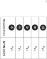
- M 2 that is an index of beam quality is described below. An embodiment of the present invention will be described based on each waveguide mode illustrated in Fig. 1 .
- the M 2 values for the waveguide modes of the optical fiber are disclosed to be 1.1 for the fundamental mode, 3.3 for the first higher-order mode, 3.3 for the second higher-order mode, and 3.1 for the third higher-order mode in Non Patent Literature 6.
- the M 2 value varies depending on a phase relationship between an excitation ratio of the first higher-order mode and the fundamental mode, and it can be understood that, if the excitation ratio of the first higher-order mode is lower than about 50%, the M 2 value becomes 2.0 or less.
- a first beam propagation method is a light transmission of propagating light with 1 kW or more from a laser for 10 m or more and outputting the light from an output end, the laser and the output end are connected with a 2-mode fiber of which the number of propagation modes is 2 at the wavelength of the light, and the light is propagated by setting an excitation ratio of the first higher-order mode of the 2-mode fiber to be 50% or less.
- the excitation ratio varies depending on an amount of axis shift from the center of the optical fiber when light is generally input to the optical fiber.
- reduction of the excitation ratio of the first higher-order mode down to 50% or less can be sufficiently realized with existing optical input/output alignment (optical axis alignment) technology.
- M 2 denotes the excitation ratio of the LP11 mode of a case where the LP01 (fundamental mode) and the LP11 mode (first higher-order mode) coexist, and M 2 is 3.3 when ⁇ (excitation ratio of the LP11 mode) is 1.0.
- ⁇ excitation ratio of the LP11 mode
- the LP11 mode will not be excited 100%, so that the worst value of the M 2 value of the 2-mode fiber is 3.3.
- a second beam propagation method is a light transmission of propagating light with 1 kW or more from a laser for 10 m or more and outputting the light from the output end, the laser and the output end are connected with a 4-mode fiber of which the number of propagation modes is 4 at the wavelength of light, and the light is propagated by setting an excitation ratio of the third higher-order mode of the 4-mode fiber to be 30% or less.
- Non Patent Literature 6 also discloses an M 2 value when the fundamental mode and the third higher-order mode coexist, and thus, it can be understood that, if the excitation ratio of the third higher-order mode is lower than about 30%, the M 2 value becomes 2 or less.
- the fundamental mode and the third higher-order mode are modes having the electric field peak at the center of the fiber, and the coupling efficiency varies depending on a spot size (MFD 2) of the light input to the fiber having a mode field diameter (MFD 1).
- MFD 2 spot size
- MFD 1 mode field diameter
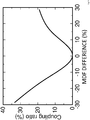
- FIG. 3 is a diagram illustrating a relationship between an MFD difference and an efficiency (rate of occurrence of the third higher-order mode) of excitation of the third higher-order mode when the vertical axis represents the efficiency of excitation of the third higher-order mode and the horizontal axis represents the MFD difference ((MFD2 - MFD1)/MFD1) input to the fiber.
- the third higher-order mode occurs according to the distance between the optical fibers (corresponding to a difference in beam diameter between input light and a fundamental mode of a 4-mode optical fiber), the distance between the fiber laser and the 4-mode optical fiber is adjusted.
- the first higher-order mode and the second higher-order mode are higher-order modes which occur due to axis shift of the fiber laser and the optical fiber and can be sufficiently suppressed from results of an axis shift and an excitation amount of the first higher-order mode.
- FIG. 6 of Non Patent Literature 6 the ground for the worst value of the M 2 value of the 2-mode fiber is illustrated in FIG. 6 of Non Patent Literature 6.
- M 2 is illustrated with respect to the excitation ratio of LP02 mode in a case where LP01 (fundamental mode) and LP02 mode (third higher-order mode) coexist, and when ⁇ (excitation ratio of LP02 mode) is 0.9, the M 2 is 3.3. Therefore, the worst value of the M 2 value of the 4-mode fiber is 3.3.
- this embodiment relates to a design method of structural parameters (diameters d of the air hole 2 and intervals A between the air holes 2) for realizing enlargement of an effective area A eff and implementing a predetermined bending loss ⁇ b in a PCF having a 1-cell core structure having air holes 2 illustrated in FIG. 4 .
- a minimum bending radius in a fundamental mode and a bending radius defining an effective cutoff of a higher-order mode are described as 140 mm, but the method according to the embodiment is not limited thereto.
- the design method includes:
- the optical fiber according to the embodiment is a photonic crystal fiber (PCF) having a 1-cell structure which has a core portion and a cladding portion that surrounds the core portion, wherein the core portion and the cladding portion are made of a medium having a uniform optical refractive index, and a plurality of uniform air holes 2 are formed in the cladding portion in the longitudinal direction.
- the 1-cell structure in the present invention denotes a structure of a photonic crystal having one defect, in which only the air holes in the central portion of the photonic crystal formed with the air holes arranged in a triangular lattice shape are made of quartz.
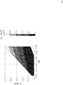
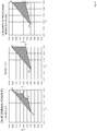
- FIG. 5 is a diagram illustrating a range of the A eff of the PCF in the region where the bending loss in the fundamental mode with a bending radius of 140 mm is 1.0 dB/m or less with respect to light having a wavelength of 1070 nm when the horizontal axis represents d/ ⁇ and the vertical axis represents ⁇ .
- the bending radius and the bending loss value in the fundamental mode are not limited to the definition and the specified value according to the present invention, but it is possible to determine the parameters used for the design according to the required characteristics.
- the A eff is obtained by using the following Mathematical Formula.
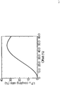
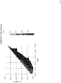
- FIG. 6 illustrates the bending loss in the first higher-order mode at a bending radius of 140 mm of the 1-cell structure PCF with respect to light having a wavelength of 1070 nm when the horizontal axis represents d/ ⁇ and the vertical axis represents ⁇ .
- the plotted range in the figure illustrates the bending loss in the first higher-order mode in the range of 1 dB/m or more (the range in which the cutoff is obtained).
- the first higher-order mode or more is sufficiently cut off, and thus, it is possible to select a region where the A eff is large.
- the air holes are set to d and ⁇ in a region surrounded by a polygon having four vertices
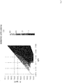
- FIG. 7 illustrates the bending loss (1 dB/m or more) in the second higher-order mode at a bending radius of 140 mm of the 1-cell structure PCF with respect to light having a wavelength of 1070 nm when the horizontal axis represents d/ ⁇ and the vertical axis represents ⁇ .
- the second higher-order mode or more is sufficiently cut off, and thus, it is possible to select a region where the A eff is large.
- the air holes are set to d and ⁇ in a region surrounded by a polygon having four vertices
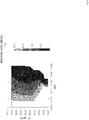
- FIG. 8 illustrates the bending loss (1 dB/m or more) in the third higher-order mode at a bending radius of 140 mm of the 1-cell structure PCF with respect to light having a wavelength of 1070 nm when the horizontal axis represents d/ ⁇ and the vertical axis represents ⁇ .
- the third higher-order mode or more is sufficiently cut off, and thus, it is possible to select a region where the A eff is large.
- the air holes are set to d and ⁇ in a region surrounded by a polygon having four vertices
- FIG. 9 illustrates the bending loss (1 dB/m or more) in the fourth higher-order mode at a bending radius of 140 mm of the 1-cell structure PCF with respect to light having a wavelength of 1070 nm when the horizontal axis represents d/ ⁇ and the vertical axis represents ⁇ .
- the fourth higher-order mode or more is sufficiently cut off, and thus, it is possible to select a region where the A eff is large.
- the air holes are set to d and ⁇ in a region surrounded by a polygon having four vertices
- the second higher-order mode or more, the third higher-order mode or more, or the fourth higher-order mode or more is sufficiently cut off, and thus, it is possible to select a region where the A eff is large.
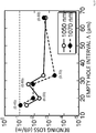
- FIG. 10 illustrates wavelength dependency of a bending loss of a PCF with a 1-cell structure.
- the solid line (open circles) and the broken line (black circles) illustrate air hole interval ( ⁇ ) dependency of the bending loss in the fundamental mode for the wavelength 1050 nm and the wavelength 1070 nm, respectively, as, and the values in parentheses in the figure indicate values of d/ ⁇ for each ⁇ .
- the PCF has characteristics in that the A eff has almost the same value regardless of the propagation wavelength and the bending loss increases as the wavelength becomes shorter.
- FIG. 10 illustrates that the structure illustrated in this design is realized in any structure where the bending loss in the fundamental mode is 0.1 dB/m or less even at a wavelength of 1050 nm and that the present design is effective at a wavelength of 1050 nm or more.
- this embodiment relates to a design method of structural parameters (diameters d of the air hole 2 and intervals A between the air holes 2) for realizing enlargement of A eff and implementing a predetermined bending loss ⁇ b in a PCF having a 7-cell core structure having a plurality of air holes 2 as illustrated in FIG. 11 .
- This design method also employs the design method described in the second embodiment.
- the optical fiber according to the embodiment is a PCF having a 7-cell structure which has a core portion and a cladding portion that surrounds the core portion, wherein the core portion and the cladding portion are made of a medium having a uniform optical refractive index, and a plurality of uniform air holes 2 are formed in the cladding portion in the longitudinal direction.
- the 7-cell structure in the present invention denotes a structure of a photonic crystal having seven defects, in which one air hole in the central portion of the photonic crystal formed with the air holes arranged in a triangular lattice shape and six air holes around the air hole are made of quartz.
- FIG. 12 is a diagram illustrating A eff in a region where the bending loss in the fundamental mode at a bending radius of 140 mm is 1.0 dB/m or less when the horizontal axis represents d/ ⁇ and the vertical axis represents ⁇ .
- the PCF according to the embodiment has a 7-cell structure, in comparison with the 3-layer structure of the 1-cell structure of Embodiment 1, it is advantageous in that the fiber outer diameter can be reduced in a region where A eff is 1000 ⁇ m 2 or more.
- a cladding diameter of 500 ⁇ m is required to achieve the A eff of 1000 ⁇ m 2
- the 4-layer 7-cell structure it can be realized with an outer diameter of about 200 ⁇ m.
- the definition of the bending loss value and cutoff in the fundamental mode is not limited to the definition and the specified value of the present invention, but it is possible to determine parameters used for the design according to the required characteristics.
- FIG. 13 illustrates the bending loss in the first higher-order (LP11) mode at a bending radius of 140 mm of the 7-cell structure PCF with respect to light having a wavelength of 1070 nm when the horizontal axis represents d/ ⁇ and the vertical axis represents ⁇ .
- the plotted range in the figure illustrates the bending loss in the first higher-order mode in the range of 1 dB/m or more (the range in which the cutoff is obtained).
- the first higher-order mode or more is sufficiently cut off, and thus, it is possible to select a region where the A eff is large.
- the air holes are set to d/ ⁇ and ⁇ in a region surrounded by a triangle having three vertices
- FIG. 14 illustrates the bending loss (1 dB/m or more) in the second higher-order mode at a bending radius of 140 mm of the 7-cell structure PCF with respect to light having a wavelength of 1070 nm when the horizontal axis represents d/ ⁇ and the vertical axis represents ⁇ .
- the second higher-order mode or more is sufficiently cut off, and thus, it is possible to select a region where the A eff is large.
- the air holes are set to d/ ⁇ and ⁇ in a region surrounded by a polygon having four vertices
- FIG. 15 illustrates the bending loss (1 dB/m or more) in the third higher-order mode at a bending radius of 140 mm of the 1-cell structure PCF with respect to light having a wavelength of 1070 nm when the horizontal axis represents d/ ⁇ and the vertical axis represents ⁇ .
- the third higher-order mode or more is sufficiently cut off, and thus, it is possible to select a region where the A eff is large.
- the air holes are set to d/ ⁇ and ⁇ in a region surrounded by a polygon having four vertices
- FIG. 16 illustrates the bending loss (1 dB/m or more) in the fourth higher-order mode at a bending radius of 140 mm of the 1-cell structure PCF with respect to light having a wavelength of 1070 nm when the horizontal axis represents d/ ⁇ and the vertical axis represents ⁇ .
- the fourth higher-order mode or more is sufficiently cut off, and thus, it is possible to select a region where A eff is large.
- the air holes are set to d/ ⁇ and ⁇ in a region surrounded by a polygon having four vertices
- the second higher-order mode or more, the third higher-order mode or more, or the fourth higher-order mode or more is sufficiently cut off, and thus, it is possible to select a region where the A eff is large.
- FIG. 17 illustrates wavelength dependency of a bending loss of a PCF with a 7-cell structure.
- the solid line (open circles) and the broken line (black circles) illustrate air hole interval ⁇ dependency of the bending loss in the fundamental mode for the wavelength 1050 nm and the wavelength 1070 nm, respectively, as, and the values in parentheses in the figure indicate values of d/ ⁇ for each ⁇ .
- the PCF has characteristics in that the A eff has almost the same value regardless of the propagation wavelength and the bending loss increases as the wavelength becomes shorter.
- 17 illustrates that the structure illustrated in this design is realized in any structure where the bending loss in the fundamental mode is 0.1 dB/m or less even at a wavelength of 1050 nm and that the present design is effective at a wavelength of 1050 nm or more.
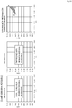
- the optical fiber design method according to the embodiment includes:
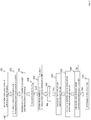
- FIG. 18 is a flowchart illustrating a procedure of the optical fiber design method according to the embodiment.
- step S01 specification value determining step
- M 2 value target beam quality
- step S02 number-of-propagation modes calculating step
- Mathematical Formula (1) Mathematical Formula (17) of Non Patent Literature 6
- step S03 an output power and a propagation distance to be used in step S03 (specification value determining step) are determined, and in step S04 (effective area calculating step), a required effective area (A eff ) is calculated by using Mathematical Formula (2) (SRS threshold definition formula (8.1.13) disclosed in Non Patent Literature 7).
- Mathematical Formula (2) SRS threshold definition formula (8.1.13) disclosed in Non Patent Literature 7.
- step S05 the number (1 + k) of propagatable modes is determined.
- step S08 bending loss calculating step
- the bending loss in the fundamental mode at the minimum bending radius to be used in the fiber structure designed in step S07 is calculated, and in a case where the bending loss exceeds a specified value in step S09, the process returns to step S05, and the number of propagatable modes is incremented by 1, and the procedure up to step S09 is repeated (mode increasing step).
- the process returns to step S01 to review the specification values such as the beam quality (M 2 value) and repeats the procedure from step S02 to determine the fiber structure.
- M 2 Cn V cutoff n + 1 , m 2 + 2 n 2 ⁇ 1 3
- step S01 specification values are determined.
- the specification values are as follows.
- Fiber loss 1 dB/km (transmission loss of fiber at the following wavelength)
- Raman gain coefficient g R 8.79 ⁇ 10 -12 (cm/W) Used wavelength of propagating light ⁇ : 1070 nm Beam quality M 2 : 1.5 or less
- Laser output power value 100 W
- Propagation distance 300 m
- Minimum bending radius 140 m
- the Raman gain coefficient gR is calculated by using Mathematical Formula (4) (Mathematical Formula (36) disclosed in Non Patent Literature 8).
- the necessary A eff is calculated to be about 160 ⁇ m 2 from Mathematical Formula (2) (the SRS threshold used in Mathematical Formula (2) is the output power determined in step S03). Since the SRS threshold calculated from the Mathematical Formula (2) varies depending on the fiber loss and g R , the necessary A eff also varies. Therefore, the fiber loss and g R are not limited to the contents of the present invention, and are appropriately changed according to the material or the like of the fiber to be used.
- step S05 fiber structure design is performed in a single-mode (the number of propagatable modes is 1).
- the structure design of PCF can be performed by structure analysis according to a finite element method disclosed in Non Patent Literature 9, an approximate analysis disclosed in Non Patent Literature 10, or the like, and in the embodiment, the structure analysis according to the finite element method is used.
- the analysis method is not limited to the embodiment, and any method capable of analyzing a structure of a fiber may be appropriately used.
- step S10 analysis is performed by using a finite element method.
- the bending loss in the fundamental mode is calculated as 1 ⁇ 10 -4 dB/m at R 140 mm. Since the propagation distance is 300 m, the total bending loss is 0.03 dB.
- step S09 it is checked whether the bending loss value at the propagation length is 0.1 dB or less. Since the bending loss after the propagation of 300 m is 0.03 dB as described above, the requirement of step S09 is satisfied, and the fiber structure is determined by this structure (step S10).
- the confinement loss in the first higher-order mode is 6 dB/m or more, this structure operates in a single-mode and causes some axis shift, and even in a case where the first higher-order mode is excited, the first higher-order mode after the propagation of 300 m has a sufficiently small excitation ratio due to the bending loss.
- the above description is an example of the structure calculated by using the design flow of FIG. 18 , and the fiber parameters may be determined as appropriate by this design flow on the basis of the target beam quality, output power, and propagation distance.
- the maximum output power (SRS threshold) and the Leff interaction length are inversely proportional to each other.
- SRS threshold the maximum output power
- the Leff and the propagation distance L become equivalent values. Therefore, in this specification, output power performance is described as a product (kW ⁇ m) of an output power and a propagation distance.
- the propagation distance is not limited to 1 km or less, and the propagation distance can be similarly applied as long as the Leff and the L can be regarded as equivalent to each other.
- Embodiments 5 to 8 will be described with reference to FIGS. 19 to 22 .
- the figures illustrate regions where, as desired PCF parameters, d/ ⁇ is represented by the horizontal axis and ⁇ is represented by the vertical axis.
- d/ ⁇ is represented by the horizontal axis
- ⁇ is represented by the vertical axis.
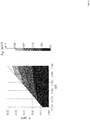
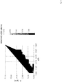
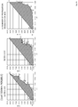
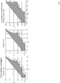
- FIG. 19 is a diagram for explaining a relationship between d/ ⁇ , ⁇ , and A eff (160 ⁇ m 2 or more) that satisfy (a) M 2 ⁇ 2.0, (b) M 2 ⁇ 3.3, and (c) the number of propagation modes is 4 or less when light having a wavelength of 1070 nm is propagated.
- the plotted region (hatched region) has a structure capable of performing 30 kW ⁇ m propagation in a PCF having a 1-cell structure.
- the air holes are set to d/A and A in a region surrounded by a polygon having vertices A1, B, C1, C2, D, E, C3, F, G, H, and I.
- the air holes are set to d/ ⁇ and ⁇ in a region surrounded by a polygon having vertices A1, B, C1, D1, C2, D2, E, F, C3, and I.
- the air holes are set to d/ ⁇ and ⁇ in a region surrounded by a polygon having vertices A1, B, C, D, E, F, G, H, I, J, and K.
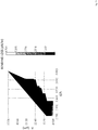
- FIG. 20 is a diagram for explaining a relationship between d/ ⁇ , ⁇ , and A eff (800 ⁇ m 2 or more) that satisfy (a) M 2 ⁇ 2.0, (b) M 2 ⁇ 3.3, and (c) the number of propagation modes is 4 or less when light having a wavelength of 1070 nm is propagated.
- the plotted region (hatched region) has a structure capable of performing 150 kW ⁇ m propagation in a PCF having a 1-cell structure.
- the air holes are set to d/A and A in a region surrounded by a polygon having vertices A2, C2, D, E, C3, F, G, H, and I.
- the air holes are set to d/ ⁇ and ⁇ in a region surrounded by a polygon having vertices A2, C2, D2, E, F, C3, and I.
- the air holes are set to d/ ⁇ and ⁇ in a region surrounded by a polygon having vertices A2, F1, G, H, I, J, and K.
- FIG. 21 is a diagram for explaining a relationship between d/ ⁇ , ⁇ , and A eff (1600 ⁇ m 2 or more) that satisfy (a) M 2 ⁇ 2.0, (b) M 2 ⁇ 3.3, and (c) the number of propagation modes is 4 or less when light having a wavelength of 1070 nm is propagated.
- the plotted region (hatched region) has a structure capable of performing 300 kW ⁇ m propagation in a PCF having a 1-cell structure.
- the air holes are set to d/A and A in a region surrounded by a polygon having vertices A3, C3, F, G, H, and I.
- the air holes are set to d/ ⁇ and ⁇ in a region surrounded by a polygon having vertices A3, C3, and I.
- the air holes are set to d/A and A in a region surrounded by a polygon having vertices A3, HI, I, J, and K.
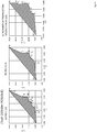
- FIG. 22 is a diagram for explaining a relationship between d/ ⁇ , ⁇ , and A eff (3200 ⁇ m 2 or more) that satisfy (a) M 2 ⁇ 2.0, (b) M 2 ⁇ 3.3, and (c) the number of propagation modes is 4 or less when light having a wavelength of 1070 nm is propagated.
- the plotted region (hatched region) has a structure capable of performing 600 kW ⁇ m propagation in a PCF having a 1-cell structure.
- d/ ⁇ and ⁇ disposed inside an area surrounded by a polygon having A4, J1, and K as its vertexes are set.
- Embodiments 9 to 13 will be described with reference to FIGS. 23 to 27 .
- the figures illustrate regions when, as desired PCF parameters, d/A is represented by the horizontal axis and A is represented by the vertical axis.
- d/A is represented by the horizontal axis
- A is represented by the vertical axis.
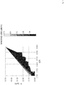
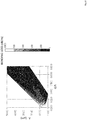
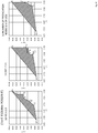
- FIG. 23 is a diagram for explaining a relationship between d/ ⁇ , ⁇ , and A eff (160 ⁇ m 2 or more) that satisfy (a) M 2 ⁇ 2.0, (b) M 2 ⁇ 3.3, and (c) the number of propagation modes is 4 or less when light having a wavelength of 1070 nm is propagated.
- the plotted region (hatched region) has a structure capable of performing 30 kW ⁇ m propagation in a PCF having a 7-cell structure.
- the air holes are set to d/A and A in a region surrounded by a polygon having vertices A1, B, C1, D, E, F, G, H, I, J, K, C3, L, M, N, O, and P.
- the air holes are set to d/A and A in a region surrounded by a polygon having vertices A1, B, C1, D, E, F, C3, G, H, I, J, and K.
- the air holes are set to d/ ⁇ and ⁇ in a region surrounded by a polygon having vertices A1, B, C, D, E, F, G, H, I, J, K, L, M, and N.
- FIG. 24 is a diagram for explaining a relationship between d/ ⁇ , ⁇ , and A eff (800 ⁇ m 2 or more) that satisfy (a) M 2 ⁇ 2.0, (b) M 2 ⁇ 3.3, and (c) the number of propagation modes is 4 or less when light having a wavelength of 1070 nm is propagated.
- the plotted area (hatched area) has a structure capable of performing 150 kW ⁇ m propagation in a PCF having a 7-cell structure.
- the air holes are set to d/A and A in a region surrounded by a polygon having vertices A2, C2, F, G, H, I, J, K, C3, L, M, N, O, and P.
- the air holes are set to d/ ⁇ and ⁇ in a region surrounded by a polygon having vertices A2, C2, F, C3, G, H, I, J, and K.
- the air holes are set to d/ ⁇ and ⁇ in a region surrounded by a polygon having vertices A2, E, F, G, H, I, J, K, L, M, and N.
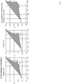
- FIG. 25 is a diagram for explaining a relationship between d/ ⁇ , ⁇ , and A eff (1600 ⁇ m 2 or more) that satisfy (a) M 2 ⁇ 2.0, (b) M 2 ⁇ 3.3, and (c) the number of propagation modes is 4 or less when light having a wavelength of 1070 nm is propagated.
- the plotted region (hatched region) has a structure capable of performing 300 kW ⁇ m propagation in a PCF having a 7-cell structure.
- the air holes are set to d/ ⁇ and ⁇ in a region surrounded by a polygon having vertices A3, G, H, I, J, K, L, M, and N.
- FIG. 26 is a diagram for explaining a relationship between d/ ⁇ , ⁇ , and A eff (3200 ⁇ m 2 or more) that satisfy (a) M 2 ⁇ 2.0, (b) M 2 ⁇ 3.3, and (c) the number of propagation modes is 4 or less when light having a wavelength of 1070 nm is propagated.
- the plotted region (hatched region) has a structure capable of performing 600 kW ⁇ m propagation in a PCF having a 7-cell structure.
- the air holes are set to d/ ⁇ and ⁇ in a region surrounded by a polygon having vertices A4, C4, N, O, and P.
- the air holes are set to d/ ⁇ and ⁇ in a region surrounded by a polygon having vertices A4, C4, J, and K.
- the air holes are set to d/ ⁇ and ⁇ in a region surrounded by a polygon having vertices A4, K1, L, M, and N.
- FIG. 27 is a diagram for explaining a relationship between d/ ⁇ , ⁇ , and A eff (4800 ⁇ m 2 or more) that satisfy (a) M 2 ⁇ 2.0, (b) M 2 ⁇ 3.3, and (c) the number of propagation modes is 4 or less when light having a wavelength of 1070 nm is propagated.
- the plotted area (hatched area) has a structure capable of performing 900 kW ⁇ m propagation in a PCF having a 7-cell structure.
- the air holes are set to d/ ⁇ and ⁇ in a region surrounded by a polygon having vertices A5, C5, O, and P.
- the air holes are set to d/ ⁇ and ⁇ in a region surrounded by a polygon having vertices A5, C5, and K.
- the air holes are set to d/ ⁇ and ⁇ in a region surrounded by a polygon having vertices A5, K, M, and N.
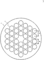
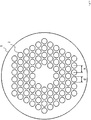
- Fig. 28 illustrates an example of the structure of a PCF according to this embodiment.
- the PCF according to this embodiment represents an optical fiber structure configured by air holes corresponding to a number smaller than the number of the air holes of the PCF illustrated in Fig. 4 .
- the structure of the PCF illustrated in Fig. 28 in a core area, similarly to the case illustrated in Fig. 4 , there is one defect in the air holes, and the number of the air holes is 12.
- a PCF has optical characteristics influenced by accuracy of the positions and the sizes of individual air holes, and the difficulty in the manufacturing or the degradation of the yield of the structure becomes remarkable as the number of the air holes is increased.
- the guidance of an optical wave is realized using a simple structure in which the number of air holes is 12 or less, and accordingly, the mass productivity is high, and the controllability of optical characteristics at the time of manufacturing is improved, which is preferable.
- high-power light of high quality having M2 to be 2.0 or less in a predetermined design range and the kW class can be transmitted.
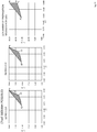
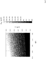
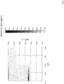
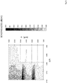
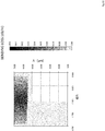
- Figs. 29 to 32 illustrate examples of design of a PCF in which the number of air holes is 12.
- Fig. 29 illustrates a structure range in which the bending loss for the basic mode is 0.1 dB/m or less.
- Figs. 30 , 31 , and 32 respectively illustrate bending loss values for an LP11 mode, an LP21 mode, and an LP02 mode, and the loss of a target mode is sufficiently large in an area (a bending loss of 1 dB/m or more) surrounded inside the range, so as to be leaked.
- a structure in which ⁇ is 50 ⁇ m or more and 65 ⁇ m or less, and d/ ⁇ is 0.79 or more and 0.88 or less or a structure in which A is 50 ⁇ m or less, and d/ ⁇ is 0.7 or more and 0.79 or less is appropriate.
- the number of air holes is 12 which is small, the yield of the manufacturing and the manufacturing accuracy are very good, and output light of M2 of 2.0 or less and the kW class is acquired, which is preferable.
- the present invention is not limited thereto.
- it may be configured such that the predetermined number of modes is two, the LP01 mode and the LP11 mode are propagated, but the LP21 mode and higher modes are not propagated. In such a case, effects similar to those of this embodiment can be acquired.
- a structure in which the LP11 mode and the LP21 mode are leaked is illustrated, and, the number of modes can be configured to be two by using an area in which Figs. 29 and 30 are overlapped, and the number of modes can be configured to be three by using an area in which Figs. 29 and 32 are overlapped.
- the number of modes can be configured to be two.
- the number of modes can be configured to be three.
- a definition formula of an SRS threshold is used, and with respect to the required beam quality, an M 2 value in a case where a propagation mode is uniformly excited from a bending loss and the number of propagatable modes is used as a threshold, so that it is possible to design a fiber structure satisfying the above conditions. Furthermore, it is possible to clarify a specific structure of high-quality high-power propagation optical fiber by using the design flow. As a specific design example, a structural example of a PCF is illustrated.
- an optical fiber design method it is possible to provide an optical fiber capable of ensuring an output power with respect to a propagation length at a desired beam quality which cannot be realized in the design of the related art.
- the fiber structure designed by using the design flow used in the present invention can satisfy required output power, propagation distance and beam quality. Even in a region of an output power of a fiber laser which has been realized only with a multi-mode with an M 2 value of 8 or more, it is possible to realize use of light having high quality beam quality for a desired propagation distance by using an optical fiber with an M 2 value of less than 8 for a fiber laser.
- the present invention can be applied to the field of laser processing using fiber laser.
Landscapes
- Physics & Mathematics (AREA)
- General Physics & Mathematics (AREA)
- Optics & Photonics (AREA)
- Chemical & Material Sciences (AREA)
- Dispersion Chemistry (AREA)
- Lasers (AREA)
- Optical Fibers, Optical Fiber Cores, And Optical Fiber Bundles (AREA)
- Optical Couplings Of Light Guides (AREA)
Claims (1)
- Procédé de conception d'une fibre optique, le procédé comprenant :la détermination d'une longueur d'onde d'une lumière de propagation, de la perte de transmission de la fibre d'une fibre en cristal photonique, PCF, (1) à la longueur d'onde de la lumière de propagation et d'un coefficient de gain Raman de la PCF (1), d'un M2 de qualité de rayonnement après la propagation dans la PCF, d'une valeur de puissance de sortie de laser, d'une distance de propagation, et d'un rayon de courbure minimum ;le calcul du plus grand nombre n de modes de propagation qui peuvent être propagés en utilisant la formule mathématique 1 ;le calcul d'une surface efficace Aeff à partir de la perte de transmission par la fibre et du coefficient de gain Raman en utilisant la formule mathématique 2 ;le calcul d'un diamètre et d'un intervalle de trous d'air (2) de la PCF satisfaisant l'Aeff ;le calcul d'une perte de courbure dans le mode fondamental au rayon de courbure minimum dans la PCF (1) ayant une structure calculée dans le calcul d'un diamètre et d'un intervalle et le calcul d'une perte de courbure dans le mode fondamental à une longueur de propagation à partir de la distance de propagation ;la vérification que la perte de courbure à la longueur de propagation est une valeur prédéterminée ou moins et la détermination de la structure de la PCF (1) calculée dans le calcul d'un diamètre et d'un intervalle ; etl'augmentation du nombre de modes de un dans un cas où la perte de courbure de la longueur de propagation est égale ou supérieure à une valeur prédéterminée dans la vérification, et la répétition du calcul d'un diamètre et d'un intervalle, le calcul de la perte de courbure, et la vérification jusqu'à ce que le nombre de modes atteigne le plus grand nombre n de modes de propagation.
[Expression numérique 1]
 Cn : Cn = 1 + ½ cos (ξ) lorsque LP1,m, Cn = 1, lorsque LPn,m (n ≠ 1)n : Nombre de modes de propagation disponibles
 Pth : valeur de seuil SRSLeff : longueur d'interaction efficace
 α : perte de transmission et
 gR : coefficient de gain Raman.
Priority Applications (1)
| Application Number | Priority Date | Filing Date | Title |
|---|---|---|---|
| EP18189688.7A EP3454100B1 (fr) | 2015-04-14 | 2016-03-18 | Procédé de conception de fibre optique |
Applications Claiming Priority (3)
| Application Number | Priority Date | Filing Date | Title |
|---|---|---|---|
| JP2015082511 | 2015-04-14 | ||
| JP2015185252 | 2015-09-18 | ||
| PCT/JP2016/058864 WO2016167080A1 (fr) | 2015-04-14 | 2016-03-18 | Procédé de conception de fibre optique |
Related Child Applications (2)
| Application Number | Title | Priority Date | Filing Date |
|---|---|---|---|
| EP18189688.7A Division EP3454100B1 (fr) | 2015-04-14 | 2016-03-18 | Procédé de conception de fibre optique |
| EP18189688.7A Division-Into EP3454100B1 (fr) | 2015-04-14 | 2016-03-18 | Procédé de conception de fibre optique |
Publications (3)
| Publication Number | Publication Date |
|---|---|
| EP3285100A1 EP3285100A1 (fr) | 2018-02-21 |
| EP3285100A4 EP3285100A4 (fr) | 2018-05-02 |
| EP3285100B1 true EP3285100B1 (fr) | 2019-05-08 |
Family
ID=57125786
Family Applications (2)
| Application Number | Title | Priority Date | Filing Date |
|---|---|---|---|
| EP18189688.7A Active EP3454100B1 (fr) | 2015-04-14 | 2016-03-18 | Procédé de conception de fibre optique |
| EP16779871.9A Active EP3285100B1 (fr) | 2015-04-14 | 2016-03-18 | Procédé de conception de fibre optique |
Family Applications Before (1)
| Application Number | Title | Priority Date | Filing Date |
|---|---|---|---|
| EP18189688.7A Active EP3454100B1 (fr) | 2015-04-14 | 2016-03-18 | Procédé de conception de fibre optique |
Country Status (5)
| Country | Link |
|---|---|
| US (1) | US10816722B2 (fr) |
| EP (2) | EP3454100B1 (fr) |
| JP (1) | JP6453447B2 (fr) |
| CN (1) | CN107533193B (fr) |
| WO (1) | WO2016167080A1 (fr) |
Families Citing this family (3)
| Publication number | Priority date | Publication date | Assignee | Title |
|---|---|---|---|---|
| CN109103741B (zh) * | 2018-09-04 | 2019-11-26 | 武汉光迅科技股份有限公司 | 一种拉曼光纤放大器的增益动态控制方法、装置和系统 |
| US11658747B2 (en) * | 2019-01-24 | 2023-05-23 | Sony Group Corporation | Optical communication apparatus, optical communication method, and optical communication system |
| WO2021205697A1 (fr) * | 2020-04-08 | 2021-10-14 | 株式会社フジクラ | Fibre optique et dispositif laser à fibre |
Family Cites Families (13)
| Publication number | Priority date | Publication date | Assignee | Title |
|---|---|---|---|---|
| CN1310045C (zh) * | 2002-10-01 | 2007-04-11 | 古河电气工业株式会社 | 光纤、光传送线路以及光纤的制造方法 |
| US7787729B2 (en) * | 2005-05-20 | 2010-08-31 | Imra America, Inc. | Single mode propagation in fibers and rods with large leakage channels |
| CN101082686A (zh) * | 2007-05-29 | 2007-12-05 | 电子科技大学 | 新型光纤参数确定方法 |
| WO2009042347A1 (fr) * | 2007-09-26 | 2009-04-02 | Imra America, Inc. | Fibres optiques en verre à âme de grande dimension |
| JP2010129886A (ja) | 2008-11-28 | 2010-06-10 | Hitachi Cable Ltd | ファイバレーザ用光ファイバ及びファイバレーザ |
| JPWO2011115146A1 (ja) | 2010-03-16 | 2013-06-27 | 古河電気工業株式会社 | ホーリーファイバ |
| JP5416059B2 (ja) * | 2010-09-03 | 2014-02-12 | 古河電気工業株式会社 | 光ファイバ |
| EP2646863A4 (fr) * | 2010-12-03 | 2015-04-08 | Ofs Fitel Llc | Fibres optiques à grande aire modale dotées d'une compensation de courbure |
| US8811784B2 (en) | 2011-10-04 | 2014-08-19 | Furukawa Electric Co., Ltd. | Optical fiber and optical transmission system |
| WO2013051295A1 (fr) | 2011-10-04 | 2013-04-11 | 古河電気工業株式会社 | Fibre optique et système de transmission optique |
| US9366810B2 (en) | 2012-08-29 | 2016-06-14 | Ofs Fitel, Llc | Double-clad, gain-producing fibers with increased cladding absoroption while maintaining single-mode operation |
| JP5843366B2 (ja) | 2012-12-14 | 2016-01-13 | 日本電信電話株式会社 | 光ファイバ |
| US9335466B2 (en) * | 2012-12-21 | 2016-05-10 | The Board Of Trustees Of The Leland Stanford Junior University | Waveguide apparatuses and methods |
-
2016
- 2016-03-18 JP JP2017512246A patent/JP6453447B2/ja active Active
- 2016-03-18 WO PCT/JP2016/058864 patent/WO2016167080A1/fr active Application Filing
- 2016-03-18 EP EP18189688.7A patent/EP3454100B1/fr active Active
- 2016-03-18 EP EP16779871.9A patent/EP3285100B1/fr active Active
- 2016-03-18 US US15/556,536 patent/US10816722B2/en active Active
- 2016-03-18 CN CN201680021858.3A patent/CN107533193B/zh active Active
Non-Patent Citations (1)
| Title |
|---|
| None * |
Also Published As
| Publication number | Publication date |
|---|---|
| EP3454100A1 (fr) | 2019-03-13 |
| CN107533193A (zh) | 2018-01-02 |
| CN107533193B (zh) | 2020-01-07 |
| JPWO2016167080A1 (ja) | 2017-09-28 |
| EP3454100B1 (fr) | 2020-06-17 |
| JP6453447B2 (ja) | 2019-01-16 |
| EP3285100A1 (fr) | 2018-02-21 |
| US20180052278A1 (en) | 2018-02-22 |
| EP3285100A4 (fr) | 2018-05-02 |
| US10816722B2 (en) | 2020-10-27 |
| WO2016167080A1 (fr) | 2016-10-20 |
Similar Documents
| Publication | Publication Date | Title |
|---|---|---|
| EP3199991A1 (fr) | Fibre optique | |
| US8797642B2 (en) | Large mode area optical fiber | |
| US20060204190A1 (en) | Large mode-area microstructure optical fiber | |
| Chafer et al. | 1-km hollow-core fiber with loss at the silica Rayleigh limit in the green spectral region | |
| EP3285100B1 (fr) | Procédé de conception de fibre optique | |
| US10539784B2 (en) | Photonic crystal fiber and high-power light transmission system | |
| US10310177B2 (en) | Photonic crystal fiber | |
| CN107924022B (zh) | 光纤和光传输系统 | |
| EP3173830B1 (fr) | Fibre optique et dispositif de source lumineuse | |
| Aleshkina et al. | Large-mode-area Bragg fiber with microstructured core for suppression of high-order modes |
Legal Events
| Date | Code | Title | Description |
|---|---|---|---|
| STAA | Information on the status of an ep patent application or granted ep patent |
Free format text: STATUS: THE INTERNATIONAL PUBLICATION HAS BEEN MADE |
|
| PUAI | Public reference made under article 153(3) epc to a published international application that has entered the european phase |
Free format text: ORIGINAL CODE: 0009012 |
|
| STAA | Information on the status of an ep patent application or granted ep patent |
Free format text: STATUS: REQUEST FOR EXAMINATION WAS MADE |
|
| 17P | Request for examination filed |
Effective date: 20171002 |
|
| AK | Designated contracting states |
Kind code of ref document: A1 Designated state(s): AL AT BE BG CH CY CZ DE DK EE ES FI FR GB GR HR HU IE IS IT LI LT LU LV MC MK MT NL NO PL PT RO RS SE SI SK SM TR |
|
| AX | Request for extension of the european patent |
Extension state: BA ME |
|
| A4 | Supplementary search report drawn up and despatched |
Effective date: 20180405 |
|
| RIC1 | Information provided on ipc code assigned before grant |
Ipc: G02B 6/02 20060101AFI20180329BHEP Ipc: G02B 6/032 20060101ALI20180329BHEP Ipc: G02B 6/028 20060101ALI20180329BHEP |
|
| DAV | Request for validation of the european patent (deleted) | ||
| DAX | Request for extension of the european patent (deleted) | ||
| GRAP | Despatch of communication of intention to grant a patent |
Free format text: ORIGINAL CODE: EPIDOSNIGR1 |
|
| STAA | Information on the status of an ep patent application or granted ep patent |
Free format text: STATUS: GRANT OF PATENT IS INTENDED |
|
| INTG | Intention to grant announced |
Effective date: 20181102 |
|
| GRAS | Grant fee paid |
Free format text: ORIGINAL CODE: EPIDOSNIGR3 |
|
| GRAA | (expected) grant |
Free format text: ORIGINAL CODE: 0009210 |
|
| STAA | Information on the status of an ep patent application or granted ep patent |
Free format text: STATUS: THE PATENT HAS BEEN GRANTED |
|
| AK | Designated contracting states |
Kind code of ref document: B1 Designated state(s): AL AT BE BG CH CY CZ DE DK EE ES FI FR GB GR HR HU IE IS IT LI LT LU LV MC MK MT NL NO PL PT RO RS SE SI SK SM TR |
|
| REG | Reference to a national code |
Ref country code: GB Ref legal event code: FG4D |
|
| REG | Reference to a national code |
Ref country code: CH Ref legal event code: EP Ref country code: AT Ref legal event code: REF Ref document number: 1131073 Country of ref document: AT Kind code of ref document: T Effective date: 20190515 |
|
| REG | Reference to a national code |
Ref country code: DE Ref legal event code: R096 Ref document number: 602016013792 Country of ref document: DE Ref country code: IE Ref legal event code: FG4D |
|
| REG | Reference to a national code |
Ref country code: NL Ref legal event code: MP Effective date: 20190508 |
|
| REG | Reference to a national code |
Ref country code: LT Ref legal event code: MG4D |
|
| PG25 | Lapsed in a contracting state [announced via postgrant information from national office to epo] |
Ref country code: NO Free format text: LAPSE BECAUSE OF FAILURE TO SUBMIT A TRANSLATION OF THE DESCRIPTION OR TO PAY THE FEE WITHIN THE PRESCRIBED TIME-LIMIT Effective date: 20190808 Ref country code: FI Free format text: LAPSE BECAUSE OF FAILURE TO SUBMIT A TRANSLATION OF THE DESCRIPTION OR TO PAY THE FEE WITHIN THE PRESCRIBED TIME-LIMIT Effective date: 20190508 Ref country code: HR Free format text: LAPSE BECAUSE OF FAILURE TO SUBMIT A TRANSLATION OF THE DESCRIPTION OR TO PAY THE FEE WITHIN THE PRESCRIBED TIME-LIMIT Effective date: 20190508 Ref country code: SE Free format text: LAPSE BECAUSE OF FAILURE TO SUBMIT A TRANSLATION OF THE DESCRIPTION OR TO PAY THE FEE WITHIN THE PRESCRIBED TIME-LIMIT Effective date: 20190508 Ref country code: AL Free format text: LAPSE BECAUSE OF FAILURE TO SUBMIT A TRANSLATION OF THE DESCRIPTION OR TO PAY THE FEE WITHIN THE PRESCRIBED TIME-LIMIT Effective date: 20190508 Ref country code: PT Free format text: LAPSE BECAUSE OF FAILURE TO SUBMIT A TRANSLATION OF THE DESCRIPTION OR TO PAY THE FEE WITHIN THE PRESCRIBED TIME-LIMIT Effective date: 20190908 Ref country code: ES Free format text: LAPSE BECAUSE OF FAILURE TO SUBMIT A TRANSLATION OF THE DESCRIPTION OR TO PAY THE FEE WITHIN THE PRESCRIBED TIME-LIMIT Effective date: 20190508 Ref country code: NL Free format text: LAPSE BECAUSE OF FAILURE TO SUBMIT A TRANSLATION OF THE DESCRIPTION OR TO PAY THE FEE WITHIN THE PRESCRIBED TIME-LIMIT Effective date: 20190508 Ref country code: LT Free format text: LAPSE BECAUSE OF FAILURE TO SUBMIT A TRANSLATION OF THE DESCRIPTION OR TO PAY THE FEE WITHIN THE PRESCRIBED TIME-LIMIT Effective date: 20190508 |
|
| PG25 | Lapsed in a contracting state [announced via postgrant information from national office to epo] |
Ref country code: BG Free format text: LAPSE BECAUSE OF FAILURE TO SUBMIT A TRANSLATION OF THE DESCRIPTION OR TO PAY THE FEE WITHIN THE PRESCRIBED TIME-LIMIT Effective date: 20190808 Ref country code: RS Free format text: LAPSE BECAUSE OF FAILURE TO SUBMIT A TRANSLATION OF THE DESCRIPTION OR TO PAY THE FEE WITHIN THE PRESCRIBED TIME-LIMIT Effective date: 20190508 Ref country code: LV Free format text: LAPSE BECAUSE OF FAILURE TO SUBMIT A TRANSLATION OF THE DESCRIPTION OR TO PAY THE FEE WITHIN THE PRESCRIBED TIME-LIMIT Effective date: 20190508 Ref country code: GR Free format text: LAPSE BECAUSE OF FAILURE TO SUBMIT A TRANSLATION OF THE DESCRIPTION OR TO PAY THE FEE WITHIN THE PRESCRIBED TIME-LIMIT Effective date: 20190809 |
|
| REG | Reference to a national code |
Ref country code: AT Ref legal event code: MK05 Ref document number: 1131073 Country of ref document: AT Kind code of ref document: T Effective date: 20190508 |
|
| PG25 | Lapsed in a contracting state [announced via postgrant information from national office to epo] |
Ref country code: SK Free format text: LAPSE BECAUSE OF FAILURE TO SUBMIT A TRANSLATION OF THE DESCRIPTION OR TO PAY THE FEE WITHIN THE PRESCRIBED TIME-LIMIT Effective date: 20190508 Ref country code: RO Free format text: LAPSE BECAUSE OF FAILURE TO SUBMIT A TRANSLATION OF THE DESCRIPTION OR TO PAY THE FEE WITHIN THE PRESCRIBED TIME-LIMIT Effective date: 20190508 Ref country code: EE Free format text: LAPSE BECAUSE OF FAILURE TO SUBMIT A TRANSLATION OF THE DESCRIPTION OR TO PAY THE FEE WITHIN THE PRESCRIBED TIME-LIMIT Effective date: 20190508 Ref country code: DK Free format text: LAPSE BECAUSE OF FAILURE TO SUBMIT A TRANSLATION OF THE DESCRIPTION OR TO PAY THE FEE WITHIN THE PRESCRIBED TIME-LIMIT Effective date: 20190508 Ref country code: AT Free format text: LAPSE BECAUSE OF FAILURE TO SUBMIT A TRANSLATION OF THE DESCRIPTION OR TO PAY THE FEE WITHIN THE PRESCRIBED TIME-LIMIT Effective date: 20190508 Ref country code: CZ Free format text: LAPSE BECAUSE OF FAILURE TO SUBMIT A TRANSLATION OF THE DESCRIPTION OR TO PAY THE FEE WITHIN THE PRESCRIBED TIME-LIMIT Effective date: 20190508 |
|
| REG | Reference to a national code |
Ref country code: DE Ref legal event code: R097 Ref document number: 602016013792 Country of ref document: DE |
|
| PG25 | Lapsed in a contracting state [announced via postgrant information from national office to epo] |
Ref country code: SM Free format text: LAPSE BECAUSE OF FAILURE TO SUBMIT A TRANSLATION OF THE DESCRIPTION OR TO PAY THE FEE WITHIN THE PRESCRIBED TIME-LIMIT Effective date: 20190508 Ref country code: IT Free format text: LAPSE BECAUSE OF FAILURE TO SUBMIT A TRANSLATION OF THE DESCRIPTION OR TO PAY THE FEE WITHIN THE PRESCRIBED TIME-LIMIT Effective date: 20190508 |
|
| PLBE | No opposition filed within time limit |
Free format text: ORIGINAL CODE: 0009261 |
|
| STAA | Information on the status of an ep patent application or granted ep patent |
Free format text: STATUS: NO OPPOSITION FILED WITHIN TIME LIMIT |
|
| PG25 | Lapsed in a contracting state [announced via postgrant information from national office to epo] |
Ref country code: TR Free format text: LAPSE BECAUSE OF FAILURE TO SUBMIT A TRANSLATION OF THE DESCRIPTION OR TO PAY THE FEE WITHIN THE PRESCRIBED TIME-LIMIT Effective date: 20190508 |
|
| 26N | No opposition filed |
Effective date: 20200211 |
|
| PG25 | Lapsed in a contracting state [announced via postgrant information from national office to epo] |
Ref country code: PL Free format text: LAPSE BECAUSE OF FAILURE TO SUBMIT A TRANSLATION OF THE DESCRIPTION OR TO PAY THE FEE WITHIN THE PRESCRIBED TIME-LIMIT Effective date: 20190508 |
|
| PG25 | Lapsed in a contracting state [announced via postgrant information from national office to epo] |
Ref country code: SI Free format text: LAPSE BECAUSE OF FAILURE TO SUBMIT A TRANSLATION OF THE DESCRIPTION OR TO PAY THE FEE WITHIN THE PRESCRIBED TIME-LIMIT Effective date: 20190508 |
|
| PG25 | Lapsed in a contracting state [announced via postgrant information from national office to epo] |
Ref country code: MC Free format text: LAPSE BECAUSE OF FAILURE TO SUBMIT A TRANSLATION OF THE DESCRIPTION OR TO PAY THE FEE WITHIN THE PRESCRIBED TIME-LIMIT Effective date: 20190508 |
|
| REG | Reference to a national code |
Ref country code: CH Ref legal event code: PL |
|
| REG | Reference to a national code |
Ref country code: BE Ref legal event code: MM Effective date: 20200331 |
|
| PG25 | Lapsed in a contracting state [announced via postgrant information from national office to epo] |
Ref country code: LU Free format text: LAPSE BECAUSE OF NON-PAYMENT OF DUE FEES Effective date: 20200318 |
|
| PG25 | Lapsed in a contracting state [announced via postgrant information from national office to epo] |
Ref country code: CH Free format text: LAPSE BECAUSE OF NON-PAYMENT OF DUE FEES Effective date: 20200331 Ref country code: LI Free format text: LAPSE BECAUSE OF NON-PAYMENT OF DUE FEES Effective date: 20200331 Ref country code: FR Free format text: LAPSE BECAUSE OF NON-PAYMENT OF DUE FEES Effective date: 20200331 Ref country code: IE Free format text: LAPSE BECAUSE OF NON-PAYMENT OF DUE FEES Effective date: 20200318 |
|
| PG25 | Lapsed in a contracting state [announced via postgrant information from national office to epo] |
Ref country code: BE Free format text: LAPSE BECAUSE OF NON-PAYMENT OF DUE FEES Effective date: 20200331 |
|
| GBPC | Gb: european patent ceased through non-payment of renewal fee |
Effective date: 20200318 |
|
| PG25 | Lapsed in a contracting state [announced via postgrant information from national office to epo] |
Ref country code: GB Free format text: LAPSE BECAUSE OF NON-PAYMENT OF DUE FEES Effective date: 20200318 |
|
| PG25 | Lapsed in a contracting state [announced via postgrant information from national office to epo] |
Ref country code: MT Free format text: LAPSE BECAUSE OF FAILURE TO SUBMIT A TRANSLATION OF THE DESCRIPTION OR TO PAY THE FEE WITHIN THE PRESCRIBED TIME-LIMIT Effective date: 20190508 Ref country code: CY Free format text: LAPSE BECAUSE OF FAILURE TO SUBMIT A TRANSLATION OF THE DESCRIPTION OR TO PAY THE FEE WITHIN THE PRESCRIBED TIME-LIMIT Effective date: 20190508 |
|
| PG25 | Lapsed in a contracting state [announced via postgrant information from national office to epo] |
Ref country code: MK Free format text: LAPSE BECAUSE OF FAILURE TO SUBMIT A TRANSLATION OF THE DESCRIPTION OR TO PAY THE FEE WITHIN THE PRESCRIBED TIME-LIMIT Effective date: 20190508 Ref country code: IS Free format text: LAPSE BECAUSE OF FAILURE TO SUBMIT A TRANSLATION OF THE DESCRIPTION OR TO PAY THE FEE WITHIN THE PRESCRIBED TIME-LIMIT Effective date: 20190908 |
|
| PGFP | Annual fee paid to national office [announced via postgrant information from national office to epo] |
Ref country code: DE Payment date: 20240320 Year of fee payment: 9 |