EP3284975B1 - Planetary axis - Google Patents
Planetary axis Download PDFInfo
- Publication number
- EP3284975B1 EP3284975B1 EP16184864.3A EP16184864A EP3284975B1 EP 3284975 B1 EP3284975 B1 EP 3284975B1 EP 16184864 A EP16184864 A EP 16184864A EP 3284975 B1 EP3284975 B1 EP 3284975B1
- Authority
- EP
- European Patent Office
- Prior art keywords
- planetary
- axis
- area
- axle
- handlebar
- Prior art date
- Legal status (The legal status is an assumption and is not a legal conclusion. Google has not performed a legal analysis and makes no representation as to the accuracy of the status listed.)
- Active
Links
- 230000005484 gravity Effects 0.000 description 26
- 125000006850 spacer group Chemical group 0.000 description 24
- 230000007246 mechanism Effects 0.000 description 21
- 230000008901 benefit Effects 0.000 description 16
- 238000005452 bending Methods 0.000 description 11
- 238000006073 displacement reaction Methods 0.000 description 7
- 239000000725 suspension Substances 0.000 description 7
- 238000010276 construction Methods 0.000 description 3
- 230000007704 transition Effects 0.000 description 3
- 230000008859 change Effects 0.000 description 2
- 238000006243 chemical reaction Methods 0.000 description 2
- 238000009434 installation Methods 0.000 description 2
- 239000000463 material Substances 0.000 description 2
- 238000012986 modification Methods 0.000 description 2
- 230000004048 modification Effects 0.000 description 2
- 230000004323 axial length Effects 0.000 description 1
- 230000005540 biological transmission Effects 0.000 description 1
- 230000001419 dependent effect Effects 0.000 description 1
- 238000011161 development Methods 0.000 description 1
- 230000018109 developmental process Effects 0.000 description 1
- 230000005489 elastic deformation Effects 0.000 description 1
- 238000004519 manufacturing process Methods 0.000 description 1
- 238000005096 rolling process Methods 0.000 description 1
Images


Classifications
-
- F—MECHANICAL ENGINEERING; LIGHTING; HEATING; WEAPONS; BLASTING
- F16—ENGINEERING ELEMENTS AND UNITS; GENERAL MEASURES FOR PRODUCING AND MAINTAINING EFFECTIVE FUNCTIONING OF MACHINES OR INSTALLATIONS; THERMAL INSULATION IN GENERAL
- F16H—GEARING
- F16H57/00—General details of gearing
- F16H57/08—General details of gearing of gearings with members having orbital motion
- F16H57/082—Planet carriers
-
- F—MECHANICAL ENGINEERING; LIGHTING; HEATING; WEAPONS; BLASTING
- F16—ENGINEERING ELEMENTS AND UNITS; GENERAL MEASURES FOR PRODUCING AND MAINTAINING EFFECTIVE FUNCTIONING OF MACHINES OR INSTALLATIONS; THERMAL INSULATION IN GENERAL
- F16H—GEARING
- F16H1/00—Toothed gearings for conveying rotary motion
- F16H1/28—Toothed gearings for conveying rotary motion with gears having orbital motion
- F16H1/2809—Toothed gearings for conveying rotary motion with gears having orbital motion with means for equalising the distribution of load on the planet-wheels
- F16H1/2836—Toothed gearings for conveying rotary motion with gears having orbital motion with means for equalising the distribution of load on the planet-wheels by allowing limited movement of the planets relative to the planet carrier or by using free floating planets
-
- F—MECHANICAL ENGINEERING; LIGHTING; HEATING; WEAPONS; BLASTING
- F16—ENGINEERING ELEMENTS AND UNITS; GENERAL MEASURES FOR PRODUCING AND MAINTAINING EFFECTIVE FUNCTIONING OF MACHINES OR INSTALLATIONS; THERMAL INSULATION IN GENERAL
- F16H—GEARING
- F16H37/00—Combinations of mechanical gearings, not provided for in groups F16H1/00 - F16H35/00
- F16H37/12—Gearings comprising primarily toothed or friction gearing, links or levers, and cams, or members of at least two of these types
-
- F—MECHANICAL ENGINEERING; LIGHTING; HEATING; WEAPONS; BLASTING
- F16—ENGINEERING ELEMENTS AND UNITS; GENERAL MEASURES FOR PRODUCING AND MAINTAINING EFFECTIVE FUNCTIONING OF MACHINES OR INSTALLATIONS; THERMAL INSULATION IN GENERAL
- F16H—GEARING
- F16H57/00—General details of gearing
- F16H57/02—Gearboxes; Mounting gearing therein
- F16H57/021—Shaft support structures, e.g. partition walls, bearing eyes, casing walls or covers with bearings
-
- F—MECHANICAL ENGINEERING; LIGHTING; HEATING; WEAPONS; BLASTING
- F16—ENGINEERING ELEMENTS AND UNITS; GENERAL MEASURES FOR PRODUCING AND MAINTAINING EFFECTIVE FUNCTIONING OF MACHINES OR INSTALLATIONS; THERMAL INSULATION IN GENERAL
- F16H—GEARING
- F16H57/00—General details of gearing
- F16H57/02—Gearboxes; Mounting gearing therein
- F16H57/023—Mounting or installation of gears or shafts in the gearboxes, e.g. methods or means for assembly
-
- F—MECHANICAL ENGINEERING; LIGHTING; HEATING; WEAPONS; BLASTING
- F16—ENGINEERING ELEMENTS AND UNITS; GENERAL MEASURES FOR PRODUCING AND MAINTAINING EFFECTIVE FUNCTIONING OF MACHINES OR INSTALLATIONS; THERMAL INSULATION IN GENERAL
- F16H—GEARING
- F16H57/00—General details of gearing
- F16H57/08—General details of gearing of gearings with members having orbital motion
- F16H2057/085—Bearings for orbital gears
Definitions
- the present invention relates to a planetary axis and a planetary gear stage.
- planetary gears planet gears rotatably mounted on planet axes mesh simultaneously with an internally toothed ring gear and with an externally toothed sun wheel. It is known to make modifications to improve the elasticity of the planetary axes in order to be able to compensate for design and load-related misalignments of the planetary gears relative to the ring gear and the sun gear.
- EP 2 559 915 A1 (General Electric Company) 02/20/2013 shows in Fig. 4 a planetary pin ("pin") 50, which in the area of its two ends each has a borehole ("bore hole”) 94 running transversely to the longitudinal axis.
- pin planetary pin
- Bore hole borehole
- the object of the present invention is to provide an improved planetary axis. This object is achieved by a planetary axis with the features specified in claims 1 and 2.
- the invention is based on the knowledge that the planet gear bearing on the planet axis of a planetary gear is comparable to a wheel suspension in an automobile, the chassis of the planet axis and the road corresponding to the planet carrier.
- the chassis is said to be even on an uneven one Avoid changing its position if possible.
- the planet axis of a planetary gear should also not change its position to the ring gear and the sun.
- the solution according to the invention therefore consists in that known wheel suspensions in the automotive sector are transferred to the planetary axis.
- the following variants of the wheel suspension have proven suitable for an analog application: wishbone axle, thrust / flexible link axle and trailing link axle.
- the planetary axis is stressed relatively little in comparison to other machine elements of the planetary gear, so that geometric modifications can be made to the planetary axis without exceeding the limits of the load-bearing capacity.
- different elastic-acting path-balancing mechanisms are used, which lead to a soft planetary gear suspension.
- a double wishbone wheel suspension in the automotive sector, two links mounted on the frame (so-called wishbone arms or wishbone arms) swing transversely to the direction of travel (double swing arm).
- the frame corresponds to the planet carrier.
- the wishbones are not articulated on the planetary axis, but are rigid; in this case they take over the spring function at the same time, which otherwise takes over a separate spring damper element.
- the handlebars connect the clamping area and the bearing seat area of the planetary axle. By varying the handlebar lengths and cross-sections, the rigidity and thus the type of steering of the system can be varied.
- the planetary axis has a variable shear stiffness via the through openings running transversely to the longitudinal axis.
- the handlebar axis generates relative displacements of bearing seat areas through handlebar elements.
- the single push / flex joint also compensates for differences in stiffness in the circumferential direction.
- the inventive The solution is characterized in that the planetary axis is at least unlatched on one side between the clamping areas in such a way that a thrust / bending link is created.
- the deflection can be controlled by a clever choice of cross section and length of the generated profile.
- This variant has advantages if there is a strong misalignment of the planetary axis bores due to a deformation of the planet carrier cheeks. However, this variant creates a bending moment in the axis mount.
- the transmission of the trailing arm axle mechanism known from the automotive field to the planetary suspension is characterized in that the center of gravity of the link region is eccentric to the center of gravity of the bearing seat area and / or to the center of gravity of the support / clamping area.
- the planet can carry out circular orbital movements around the center of gravity of the eccentric body, the radius of the circular path corresponding to the distance between the center of gravity of the two bodies.
- the planetary axle is designed analogously to a wishbone axle and, between a clamping area for clamping in a planet carrier cheek and a bearing seat area for receiving a planetary bearing, has a handlebar area with at least one through opening running transverse to the planetary axis and at least two wishbone arms connecting the clamping area and the bearing seat area.
- the planetary axis is designed analogously to a thrust / flexible link axis and has a handlebar region with a bar between a clamping area for clamping in a planet carrier cheek and a bearing seat area for receiving a planetary bearing.
- the planetary axle is designed analogously to a trailing arm axle and has a handlebar area between a clamping area for clamping in a planet carrier cheek and a bearing seat area for receiving a planetary bearing, the center of gravity of the handlebar area being formed eccentrically to the center axis of the bearing seat area and / or the center axis of the clamping area is.
- the object is achieved by a planetary gear stage with a planetary axis according to the invention.
- the through opening is oriented perpendicular to an orbit of the planetary axis.
- the plane of the beam runs radially to a sun gear of the planetary gear stage.
- the center of gravity of the link region is formed eccentrically radially to a sun gear of the planetary gear stage.
- the wishbones can have different lengths and cross sections. The advantage here is that the spring stiffness of the wishbones can be adjusted.
- the transition of the handlebars to the neighboring areas can be provided with radii or elliptical fillets. The advantage here is that no voltage peaks occur or voltage peaks are reduced.
- the axis is designed in such a way that the axis itself generates / translates and / or rotates displacements of the partial regions relative to one another under load.
- the advantage here is that the desired deflections of the axis can be set to compensate for axis restriction and axis inclination errors.
- a spacer sleeve with the highest possible rigidity is interposed to widen the bearing seat area between the bearing seat of the axle and the bearings (roller or slide bearings).
- the advantage here is that longer wishbone arms are possible with the same installation space in relation to conventional designs. An increased deflection can thus be achieved.
- a high degree of rigidity ensures that the force is distributed evenly across the width of the bearing.
- the axis consists of one or more arbitrary uniform profiles.
- the advantage here is that they are easy to manufacture.
- the handlebar mechanism is fabricated and / or positively and / or non-positively.
- the advantage here is that the handlebar mechanism can be composed of bodies made of different different materials. Furthermore, a handlebar mechanism made of several elements is advantageous for assembly.
- the axis has at least one jump in the shear stiffness profile transverse to the axis. It is a property of the axis. The advantage is that you can achieve higher deformations compared to axles with constant shear rigidity in a small installation space. The reason for this is that there is shear and bending stiffness superimpose and in the case of short bodies the shear stiffness is dominant over the bending stiffness.
- the outer dimensions (diameter) of the handlebar area are smaller than those of the clamping area or bearing seat area.
- the advantage here is that sleeves without heels can be used.
- the stiffness and deformation properties of the axle can be adjusted by varying the length and height of the handlebars (handlebar profiles) and their position over the height of the axle.
- the advantage here is that, on the one hand, the nesting of the axis into the planetary axis bore and, on the other hand, the inclination of the axis relative to the planet carrier can be adjusted. In the automobile, the camber is stopped.
- the planetary axis is designed as a simple thrust / bending link.
- the advantage here is that the axis between the clamping area and the bearing seat enables elastic translatory and rotary deflections.
- the planetary axis is designed as a multiple thrust / bending link.
- the advantage here is that at least two directional stiffness properties can be formed between the clamping point and the bearing seat and thus axis inclination and axis restriction errors can be compensated for.
- the axle is supported / clamped on one side, on both sides or in the center.
- the advantage here is that the axle can be used in a planet carrier with one cheek, in a conventional one with two cheeks or one with a central cheek, similar to a bogie plate.
- the axis is positively and / or non-positively secured against rotation in the planet carrier.
- the advantage here is that this avoids twisting or axial movement of the axis in the planet carrier.
- the axis of the bearing seat is arranged eccentrically to the axis of gravity of the eccentric profile.
- the advantage here is that the bearing seat can perform an elastic pivoting movement with respect to the clamping point about the axis of gravity of the eccentric region.
- the axis has tapered areas.
- conical press seats can also be realized with conical counterparts.
- the center of gravity of the link region is formed eccentrically to the central axis of the planetary axis, wherein a plane spanned by the centerline and central axis can be oriented as desired, preferably tangentially or perpendicular to the circular path of the planet.
- the predominantly creative solution consists at least of a support / clamping area 1 for supporting or clamping the planetary axis in a planet carrier, a handlebar area 2 with a defined axial length 200 and a bearing seat area 3 with a bearing seat for mounting / receiving the bearing.
- the handlebar region 2 has at least one through-opening 12 with any cross-section transverse to the central axis R.
- the material of the planetary axis 100 which remains in the handlebar region 2 after the through-opening 12 has been produced, forms at least two wishbone arms 7, 8, which connect the regions 1 and 3 ,
- the control arm 7, 8 can have any cross section 9, 10. Due to the unequal design of the handlebar lengths, a defined inclination of the axes of area 1 to area 3 can be generated or superimposed for parallel displacement.
- the transition of the links 7, 8 to the neighboring areas is preferably provided with radii or elliptical fillets 11.
- the diameter of the handlebar area 2 can be smaller than the diameter of the clamping area 1 or the bearing seat area 3. This is necessary so that the handlebars 7, 8 do not collide with an optional spacer sleeve when deflecting.
- the axis for the storage of gear wheels has a clamping area 1, 5, a central area 3 with the bearing seat, and in each case between clamping area 1, 5 and bearing seat 3, a wishbone area 2 for fixing in a double-walled frame, that is, the double-walled planet carrier 4.
- the wishbones 7, 8, 14, 15 result from the introduction of two through openings 12, 13 lying transversely to the central axis R.
- the wishbones 7, 8, 14, 15 permit an elastic parallel displacement of the central area 3 to the two clamping areas 1, 5.
- the deflection of the axle areas 1, 3, 5 can be adjusted by varying the handlebar cross sections 9, 10.
- the links 7, 8, 14, 15 can have different cross sections and lengths.
- the transition of the links 7, 8, 14, 15 to the neighboring areas 1, 3, 5 is preferably provided with radii or elliptical fillets 11.
- the diameter of the handlebar area 2, 4 can be made smaller than that of the clamping areas 1, 5 or the bearing seat area 3. This is necessary so that the handlebars 7, 8, 14, 15 do not collide with an optional spacer sleeve when deflecting.
- Fig. 7 shows a perspective view of a two-sided clamped axle with a double wishbone mechanism with differently designed links 7, 8, 14, 15.
- Fig. 8 shows a first embodiment of a planetary gear plain bearing with double wishbone and spacer sleeve 17.
- a planetary axis 100 is clamped with its clamping areas 1, 5 located at the ends of the planetary axis 100 in two planet carrier cheeks 16.
- the area of the planetary axle 100 which is exposed in between is divided into an axially central bearing seat area 3 and two handlebar areas 2, 4 each lying between the bearing seat area 3 and the clamping areas 1, 5.
- the handlebar areas 2, 4 each have a through opening 12 running transversely to the planetary axis , 13 on.
- the two through openings 12, 13 have different cross sections, so that the links 7, 8, 14, 15 at both through openings 12, 13, ie the webs of the planetary axis 100 remaining in the handlebar areas 2, 4, are also of different widths.
- the section AA is in Fig. 6 shown.
- a spacer sleeve 17 sits on the planet axis 100 between the planet carrier cheeks 16, which in turn is surrounded by a slide bearing sleeve 19 and a planet gear 20.
- the spacer sleeve 17 has an undercut 18 on its inner diameter at each end, so that the spacer sleeve 17 does not touch the planetary axis 100 in the handlebar areas 2, 4.
- the spacer sleeve 17 touches the planet axis 100 only in the central bearing seat area 3, while in the adjacent handlebar areas 2, 4 the spacer sleeve 17 is radially spaced from the planet axis 100.
- the radial spacing in the area of the handlebar areas 2, 4 serves to allow the planetary axis 100 to be radially displaced or deformed in the handlebar areas 2, 4.
- Fig. 9 shows an embodiment of a planetary gear plain bearing with double wishbone and without spacer sleeve.
- execution shown largely corresponds to that in Fig. 8 shown embodiment, with the difference that the in Fig. 9 shown embodiment is carried out without a spacer sleeve 17.
- the slide bearing sleeve 19 is seated directly on the planetary axis 100, although - analogously to that in FIG Fig. 8 Shown embodiment - the slide bearing sleeve 19 has an undercut 18 at its inner diameter at each end, so that the slide bearing sleeve 19 does not touch the planetary axis 100 in the handlebar areas 2, 4.
- Fig. 9 shows an embodiment of a planetary gear plain bearing with double wishbone and without spacer sleeve.
- FIG. 10 shows an embodiment of a planetary gear roller bearing with double wishbone and spacer sleeve.
- execution shown largely corresponds to that in Fig. 8 shown embodiment, with the difference that the in Fig. 10 shown embodiment has a bearing inner ring 22 and roller bearing 21 instead of the plain bearing sleeve 19.
- Fig. 11 shows an embodiment of a planetary gear roller bearing with double wishbone and without spacer sleeve.
- execution shown largely corresponds to that in Fig. 10 shown embodiment, with the difference that the in Fig. 11 shown embodiment is carried out without a spacer sleeve 17.
- the bearing inner rings 22 sit directly on the planet axis 100, but the bearing inner rings 22 and the rolling bearings surrounding the bearing inner rings 22 21 are arranged exclusively in the central bearing seat area 3.
- the radial displacement or deformation of the planetary axis 100 in the handlebar areas 2, 4 is negligible compared to the resulting space between the planetary axis 100 and the planetary gear 20.
- Fig. 12 shows schematically the deflection of the planetary axis 100, which is reflected in a change in position ⁇ of the bearing seat region 3 of the planetary axis 100, under load F in the case of coaxial supports 23, 24.
- the planetary axis system in this case deflects itself symmetrically.
- the roller bearing seat 3 deflects horizontally by the path difference ⁇ .
- Fig. 13 shows in simplified form the deflection of the planetary axis 100 in the case of eccentrically positioned supports 23, 24, for example in the case of a twisted planet carrier.
- the soft transverse bending links 7, 8, 14, 15 can compensate for the relative displacement e in the support 24, the bearing seat 3 also remains horizontal. This applies in the event that the clamping areas 1, 5 of the planetary axis 100 are clamped rigidly. Depending on the bending / shear stiffness of the handlebars, different reaction forces arise in the clamping. If the clamping areas 1, 5 are not clamped rigidly, the bending / shear stiffness of the right link 14, 15 to that of the left link 7, 8 must be set to the desired translational deflection. The reaction force in the clamping points 1, 5 is almost the same in this case.
- the planetary axis 100 has at a first end a first region 1 for support / clamping in the planet carrier, followed by a first thrust / bending link 25, then a bearing seat region 3 for receiving the gearwheel with the associated bearing mechanism, followed by a second thrust / Flexure 26 and then at another end a second area 5 for support / clamping in the planet carrier.
- the relative rotation of the two planet carrier cheeks relative to one another also results in a relative rotation of the two opposite planetary axis bores. This relative rotation of the axle receptacles can thus be elastically compensated for by the planetary axle 100, and micro-slip between the axle and the planetary axle bore can thus be avoided.
- the planetary axle 100 has at a first end a first area 1 for support / clamping in the planet carrier, followed by a first trailing arm area 2 with an eccentrically lying profile 27, then a bearing seat area 3 for receiving the gearwheel with the associated bearing mechanism, and then a second one Trailing arm area 4 with an eccentrically lying profile 28, and then at another end a second area 5 for support / clamping in the planet carrier.
- the axis of gravity 31 of the handlebar regions 27, 28 lies in the illustrated embodiment approximately in the region of the central axis of the eccentrically lying profiles 27, 28.
- the axis of gravity 32 of the clamping regions 1, 5 lies approximately in the Area of the center axis of the planetary axis 100, as well as the center of gravity 33 of the bearing seat area 3.
- An axis 100 for the storage of gears has for fixing in a double-walled frame, i.e. the planet carrier, at both ends a clamping area 1, 5, a central area 3 with the bearing seat and between the clamping area 1, 5 and the bearing seat area 3 a trailing arm area 2 and 4.
- the trailing arm axis is characterized in that the bearing seat area 3 and the clamping area 1, 5 are connected by a link area 2, 5 with any profile, the axis of gravity 31 of which is eccentric to the axis of gravity 33 of the bearing area 3.
- the bearing seat area 3 can now perform an elastic rotary movement about the center of gravity 31 of the handlebar areas 2, 4 on a circular path, the radius of which corresponds to the distance g of the center of gravity 31, 33.
- a planetary axis 100 is clamped with its clamping areas 1, 5 located at the ends of the planetary axis 100 in two planet carrier cheeks 16.
- the area of the planetary axle 100 which is exposed in between is divided into an axially central bearing seat area 3 and two handlebar areas 2, 4 each lying between the bearing seat area 3 and the clamping areas 1, 5.
- the handlebar areas 2, 4 each have a reference to the center of gravity 33 of the bearing seat area 3 eccentrically arranged profile 27, 28.
- the offset g indicates the distance between the center of gravity 33 of the bearing seat area 3 and the center of gravity 31 of the handlebar areas 2, 4.
- the section AA of the first profile 27 is in Fig. 24 shown.
- a spacer sleeve 17 is seated in the bearing seat area 3 between the planet carrier cheeks 16, which in turn is surrounded by inner bearing rings 22, roller bearings 21 and a planet gear 20.
- the spacer sleeve 17 has an undercut 18 at its inner diameter at each end, so that the spacer sleeve 17 does not touch the planetary axis 100, more precisely: the eccentric profiles 27, 28, in the handlebar areas 2, 4.
- the spacer sleeve 17 touches the planet axis 100 only in the central bearing seat area 3, while in the adjacent handlebar areas 2, 4 the spacer sleeve 17 is radially spaced from the planet axis 100.
- the radial spacing in the area of the handlebar areas 2, 4 serves to allow the planetary axis 100 to be radially displaced or deformed in the handlebar areas 2, 4.
- the trailing arm variant can also be designed without a spacer sleeve 17, alternatively with sliding bearings with and without a spacer sleeve 17.
- FIG. 25 and 26 each show a section through a further embodiment of a trailing arm profile 27, which is formed in the handlebar areas 2, 4 of a planetary axis. It is in Fig. 25 shown profile 27 is a trailing arm profile, whereas that in Fig. 26 Profile 27 shown is a double transverse trailing arm profile.
- Fig. 27 shows a section through an embodiment of a divided handlebar profile.
- a split construction for wishbones and for trailing arms with two single links is possible.
- the design largely follows the design according to Fig. 10 , but with the differences that the handlebar profiles in handlebar areas 2 and 4 according to Fig. 16 are formed and that the bearing seat area 3 with the bearing seat is interrupted by a free space 34, in other words: the planetary axis 100 consists of two halves which do not touch axially. This construction can also be seen as two separate planetary axles 100a, 100b with single links 2, 4.
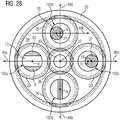
- Fig. 28 serves to illustrate an advantageous orientation of the profiles arranged in the handlebar area in relation to the overall system planetary gear stage.
- Fig. 28 shows a cross section through handlebar areas 2 of planetary axles 100a, 110b, 110c and 100d of a planetary gear stage with a fixed ring gear 35, a rotatably mounted sun gear 36, four rotatably mounted planet gears 20 with central axes R and a rotatably mounted planet carrier with a planet carrier cheek 38, in the viewing direction the central axis of rotation 37 of the planet carrier.
- the four planetary axles 100a, 100b, 100c, 100d, on which the planet gears 20 are rotatably mounted, are clamped into the planet carrier cheek 38 at right angles to them, distributed uniformly over the circumference.
- the teeth of the planet gears 20 mesh with the ring gear 35 surrounding the planet carrier 38.
- the sun gear 36 which also meshes with the planet gears 20, is arranged in the axial center 37 of the planet carrier.
- the sun gear is non-rotatably seated on a sun gear shaft 39 which is rotatably mounted about the axis of rotation 37.
- a first planetary axle 100a is configured analogously to a wishbone axle, with a cross section in the handlebar region as in FIG Fig. 6 shown.
- the through hole 12 extends perpendicular to the circular movement of the planetary axis 100a about the axis of rotation 37 of the planet carrier;
- the two wishbone arms 9, 10 of the handlebar region run parallel to a radial beam 40a, which begins at the axis of rotation 37 of the planet carrier and runs through the central axis R of the planetary axis 100a.
- a second planetary axis 100b is designed analogously to a push / flexure axis, with a cross section in the handlebar area as in Fig. 19 shown.
- the bar 25 of the handlebar region runs along a radial beam 40b, which begins at the axis of rotation 37 of the planet carrier and runs through the central axis R of the planetary axis 100b.
- a third planetary axle 100c is designed analogously to a trailing arm axle, with a cross section in the handlebar region as in FIG Fig. 22 shown.
- the axis of gravity 31 of the eccentrically arranged profile 27 is along a radial beam 40c, which begins at the axis of rotation 37 of the planet carrier and runs through the central axis R of the planetary axis 100c, offset by a distance g from the axis of gravity 33, in the direction of the beam.
- the axis of gravity 31 of the handlebar region 2 is thus formed eccentrically to the central axis R of the planetary axis 100 such that a plane spanned by the central axis 31 and the central axis R extends perpendicular to the circular path of the planet.
- a fourth planetary axle 100d is designed analogously to a trailing arm axle, with a cross section in the handlebar region as in FIG Fig. 22 shown.
- the center of gravity 31 of the eccentrically arranged profile 28 is transverse to a radial beam 40d, which begins at the axis of rotation 37 of the planet carrier and runs through the central axis R of the planetary axis 100d, by a distance g from the center of gravity 33, in the opposite direction a beam 40f which runs parallel to the radial beam 40c and through the central axis R of the planetary axis 100d.
- the axis of gravity 31 of the handlebar region 2 is thus designed eccentrically to the central axis R of the planetary axis 100 such that a plane spanned by the central axis 31 and the central axis R extends tangentially to the circular path of the planet.
Description
Die vorliegende Erfindung betrifft eine Planetenachse und eine Planetengetriebestufe.
In Planetengetrieben kämmen auf Planetenachsen drehbar gelagerte Planetenräder gleichzeitig mit einem innenverzahnten Hohlrad und mit einem außenverzahnten Sonnenrad. Es ist bekannt, an den Planetenachsen ihre elastische Nachgiebigkeit verbessernde Modifikationen vorzunehmen, um konstruktions- und lastbedingte Schiefstellungen der Planetenräder relativ zu dem Hohlrad und dem Sonnenrad ausgleichen zu können.The present invention relates to a planetary axis and a planetary gear stage.
In planetary gears, planet gears rotatably mounted on planet axes mesh simultaneously with an internally toothed ring gear and with an externally toothed sun wheel. It is known to make modifications to improve the elasticity of the planetary axes in order to be able to compensate for design and load-related misalignments of the planetary gears relative to the ring gear and the sun gear.
Aufgabe der vorliegenden Erfindung ist es, eine verbesserte Planetenachse bereitzustellen.
Diese Aufgabe wird erfindungsgemäß durch eine Planetenachse mit den in Anspruch 1 und 2 angegebenen Merkmalen gelöst.The object of the present invention is to provide an improved planetary axis.
This object is achieved by a planetary axis with the features specified in
Die Erfindung beruht auf der Erkenntnis, dass die Planetenradlagerung auf der Planetenachse eines Planetengetriebes vergleichbar ist zu einer Radaufhängung bei einem Automobil, wobei das Chassis der Planetenachse und die Straße dem Planetenträger entsprechen. Das Chassis soll auch bei einer unebenen Fahrbahn seine Lage möglichst nicht verändern. Die Planetenachse eines Planetengetriebes sollte seine Lage zum Hohlrad und zur Sonne ebenfalls nicht verändern.The invention is based on the knowledge that the planet gear bearing on the planet axis of a planetary gear is comparable to a wheel suspension in an automobile, the chassis of the planet axis and the road corresponding to the planet carrier. The chassis is said to be even on an uneven one Avoid changing its position if possible. The planet axis of a planetary gear should also not change its position to the ring gear and the sun.
Die erfinderische Lösung besteht also darin, dass im Automobilbereich bekannte Radaufhängungen auf die Planetenachse übertragen werden. Als für eine analoge Anwendung geeignet haben sich folgende Varianten der Radaufhängung erwiesen: Querlenkerachse, Schub-/Biegelenkerachse und Längslenkerachse.The solution according to the invention therefore consists in that known wheel suspensions in the automotive sector are transferred to the planetary axis. The following variants of the wheel suspension have proven suitable for an analog application: wishbone axle, thrust / flexible link axle and trailing link axle.
Die Planetenachse ist im Vergleich zu anderen Maschinenelementen des Planetengetriebes relativ gering beansprucht, sodass an der Planetenachse geometrische Modifikationen vorgenommen werden können ohne die Grenzen der Beanspruchbarkeit zu überschreiten. Dafür werden verschiedene elastisch wirkende wegausgleichende Mechanismen genutzt, die zu einer weichen Planetenradaufhängung führen.The planetary axis is stressed relatively little in comparison to other machine elements of the planetary gear, so that geometric modifications can be made to the planetary axis without exceeding the limits of the load-bearing capacity. For this, different elastic-acting path-balancing mechanisms are used, which lead to a soft planetary gear suspension.
Bei einer Doppelquerlenker-Radaufhängung im Automobilbereich schwingen zwei am Gestell gelagerte Glieder (sogenannte Querlenker oder Querlenkerarme) quer zur Fahrtrichtung (Doppelschwinge). Dem Gestell entspricht bei einem Planetengetriebe der Planetenträger. Gegenüber dem Fahrzeugmechanismus sind die Querlenker bei der Planetenachse jedoch nicht gelenkig gelagert sondern biegesteif; in diesem Fall übernehmen sie gleichzeitig die Federfunktion, welches sonst ein separates Feder-Dämpferelement übernimmt. Die Lenker verbinden den Einspannbereich und Lagersitzbereich der Planetenachse. Durch Variation der Lenkerlängen und -querschnitte kann der Steifigkeit und somit Art der Einlenkung des Systems variiert werden. Die Planetenachse hat über die quer zur Längsachse verlaufenden Durchgangsöffnungen eine variable Schubsteifigkeit. Die Lenkerachse erzeugt Relativverschiebungen von Lagersitzbereichen durch Lenkerelemente.In a double wishbone wheel suspension in the automotive sector, two links mounted on the frame (so-called wishbone arms or wishbone arms) swing transversely to the direction of travel (double swing arm). In the case of a planetary gear, the frame corresponds to the planet carrier. Compared to the vehicle mechanism, the wishbones are not articulated on the planetary axis, but are rigid; in this case they take over the spring function at the same time, which otherwise takes over a separate spring damper element. The handlebars connect the clamping area and the bearing seat area of the planetary axle. By varying the handlebar lengths and cross-sections, the rigidity and thus the type of steering of the system can be varied. The planetary axis has a variable shear stiffness via the through openings running transversely to the longitudinal axis. The handlebar axis generates relative displacements of bearing seat areas through handlebar elements.
Der Einfach-Schub-/Biegelenker gleicht ebenfalls Steifigkeitsunterschiede in Umfangsrichtung aus. Die erfinderische Lösung ist dadurch gekennzeichnet, dass die Planetenachse zwischen den Einspannbereichen zumindest einseitig so ausgeklinkt ist, dass ein Schub-/Biegelenker entsteht. Durch eine geschickte Wahl von Querschnitt und Länge des erzeugten Profils kann die Auslenkung gesteuert werden. Diese Variante hat Vorteile, wenn infolge einer Verformung der Planetenträgerwangen eine starke Schiefstellung der Planetenachsbohrungen vorliegt. Diese Variante erzeugt jedoch ein Biegemoment in der Achsaufnahme.The single push / flex joint also compensates for differences in stiffness in the circumferential direction. The inventive The solution is characterized in that the planetary axis is at least unlatched on one side between the clamping areas in such a way that a thrust / bending link is created. The deflection can be controlled by a clever choice of cross section and length of the generated profile. This variant has advantages if there is a strong misalignment of the planetary axis bores due to a deformation of the planet carrier cheeks. However, this variant creates a bending moment in the axis mount.
Die Übertragung der aus dem Automobilbereich bekannten Längslenkerachse-Mechanik auf die Planetenaufhängung ist dadurch gekennzeichnet, dass die Schwerachse des Lenkerbereichs exzentrisch zur Schwerachse des Lagersitzbereichs und/oder zu der Schwerachse des Auflager/Einspannbereichs ausgeführt ist. Durch elastisches Tordieren des Lenkerbereichs kann der Planet Kreisbahnbewegungen um die Schwerachse des exzentrischen Körpers ausführen, wobei der Radius der Kreisbahn dem Abstand der Schwerachsen der beiden Körper entspricht.The transmission of the trailing arm axle mechanism known from the automotive field to the planetary suspension is characterized in that the center of gravity of the link region is eccentric to the center of gravity of the bearing seat area and / or to the center of gravity of the support / clamping area. By twisting the handlebar region elastically, the planet can carry out circular orbital movements around the center of gravity of the eccentric body, the radius of the circular path corresponding to the distance between the center of gravity of the two bodies.
Vorteilhafte Ausgestaltungen und Weiterbildungen der Erfindung sind in den abhängigen Ansprüchen angegeben.Advantageous refinements and developments of the invention are specified in the dependent claims.
Gemäß der Erfindung ist die Planetenachse analog zu einer Querlenkerachse ausgebildet und weist zwischen einem Einspannungsbereich zum Einspannen in eine Planetenträgerwange und einem Lagersitzbereich zur Aufnahme eines Planetenlagers einen Lenkerbereich mit zumindest einer quer zur Planetenachse verlaufenden Durchgangsöffnung und zumindest zwei den Einspannungsbereich und den Lagersitzbereich verbindenden Querlenkerarmen auf.
Gemäß einer bevorzugten Ausgestaltung der Erfindung ist die Planetenachse analog zu einer Schub-/Biegelenkerachse ausgebildet und weist zwischen einem Einspannungsbereich zum Einspannen in eine Planetenträgerwange und einem Lagersitzbereich zur Aufnahme eines Planetenlagers einen Lenkerbereich mit einem Balken auf.According to the invention, the planetary axle is designed analogously to a wishbone axle and, between a clamping area for clamping in a planet carrier cheek and a bearing seat area for receiving a planetary bearing, has a handlebar area with at least one through opening running transverse to the planetary axis and at least two wishbone arms connecting the clamping area and the bearing seat area.
According to a preferred embodiment of the invention, the planetary axis is designed analogously to a thrust / flexible link axis and has a handlebar region with a bar between a clamping area for clamping in a planet carrier cheek and a bearing seat area for receiving a planetary bearing.
Gemäß der Erfindung ist die Planetenachse analog zu einer Längslenkerachse ausgebildet und weist zwischen einem Einspannungsbereich zum Einspannen in eine Planetenträgerwange und einem Lagersitzbereich zur Aufnahme eines Planetenlagers einen Lenkerbereich auf, wobei die Schwerachse des Lenkerbereichs exzentrisch zur Schwerachse des Lagersitzbereichs und/oder zur Schwerachse des Einspannbereichs ausgebildet ist.
Außerdem wird die Aufgabe gelöst durch eine Planetengetriebestufe mit einer erfindungsgemäßen Planetenachse.
Gemäß einer bevorzugten Ausgestaltung der Planetengetriebestufe ist im Falle einer analog zu einer Querlenkerachse ausgebildeten Planetenachse die Durchgangsöffnung senkrecht zu einer Umlaufbahn der Planetenachse ausgerichtet.
Gemäß einer bevorzugten Ausgestaltung der Planetengetriebestufe verläuft im Falle einer analog zu einer Schub-/Biegelenkerachse ausgebildeten Planetenachse die Ebene des Balkens radial zu einem Sonnenrad der Planetengetriebestufe.
Gemäß einer bevorzugten Ausgestaltung der Planetengetriebestufe ist im Falle einer analog zu einer Längslenkerachse ausgebildeten Planetenachse die Schwerachse des Lenkerbereichs exzentrisch radial zu einem Sonnenrad der Planetengetriebestufe ausgebildet.
Die Querlenker können unterschiedliche Längen und Querschnitte haben. Von Vorteil ist dabei, dass die Federsteifigkeit der Querlenker eingestellt werden kann.
Der Übergang der Lenker zu den Nachbarbereichen ist kann mit Radien oder elliptischer Ausrundungen versehen sein. Von Vorteil ist dabei, dass keine Spannungsspitzen entstehen bzw. Spannungsspitzen gemindert werden.According to the invention, the planetary axle is designed analogously to a trailing arm axle and has a handlebar area between a clamping area for clamping in a planet carrier cheek and a bearing seat area for receiving a planetary bearing, the center of gravity of the handlebar area being formed eccentrically to the center axis of the bearing seat area and / or the center axis of the clamping area is.
In addition, the object is achieved by a planetary gear stage with a planetary axis according to the invention.
According to a preferred embodiment of the planetary gear stage, in the case of a planetary axis designed analogously to a wishbone axis, the through opening is oriented perpendicular to an orbit of the planetary axis.
According to a preferred embodiment of the planetary gear stage, in the case of a planetary axis designed analogously to a thrust / flexible link axis, the plane of the beam runs radially to a sun gear of the planetary gear stage.
According to a preferred embodiment of the planetary gear stage, in the case of a planetary axis designed analogously to a trailing arm axis, the center of gravity of the link region is formed eccentrically radially to a sun gear of the planetary gear stage.
The wishbones can have different lengths and cross sections. The advantage here is that the spring stiffness of the wishbones can be adjusted.
The transition of the handlebars to the neighboring areas can be provided with radii or elliptical fillets. The advantage here is that no voltage peaks occur or voltage peaks are reduced.
Gemäß einer bevorzugten Ausgestaltung der Erfindung ist die Achse so gestaltet das unter Last die Achse selbst geführte/gerichtete elastische translatorisch und/oder rotatorische Verlagerungen der Teilbereiche zueinander erzeugt. Von Vorteil ist dabei, dass gezielt gewünschte Auslenkungen der Achse zum Ausgleich von Achsschränkungs- und Achsneigungsfehlern eingestellt werden können.According to a preferred embodiment of the invention, the axis is designed in such a way that the axis itself generates / translates and / or rotates displacements of the partial regions relative to one another under load. The advantage here is that the desired deflections of the axis can be set to compensate for axis restriction and axis inclination errors.
Gemäß einer bevorzugten Ausgestaltung der Erfindung ist zur Verbreiterung des Lagersitzbereichs zwischen dem Lagersitz der Achse und den Lagern (Wälz- oder Gleitlager) eine Distanzhülse mit möglichst hoher Steifigkeit zwischengeschaltet. Von Vorteil ist dabei, dass dadurch längere Querlenkerarme bei gleichem Bauraum in Bezug auf herkömmliche Ausführungen möglich sind. Somit kann eine erhöhte Auslenkung erreicht werden. Durch eine hohe Steifigkeit wird eine gleichmäßige Kraftaufteilung im Lager über dessen Breite erreicht.According to a preferred embodiment of the invention, a spacer sleeve with the highest possible rigidity is interposed to widen the bearing seat area between the bearing seat of the axle and the bearings (roller or slide bearings). The advantage here is that longer wishbone arms are possible with the same installation space in relation to conventional designs. An increased deflection can thus be achieved. A high degree of rigidity ensures that the force is distributed evenly across the width of the bearing.
Gemäß einer bevorzugten Ausgestaltung der Erfindung besteht die Achse aus einem oder mehreren beliebigen gleichförmigen Profilen. Von Vorteil ist dabei, dass diese einfach herzustellen sind.According to a preferred embodiment of the invention, the axis consists of one or more arbitrary uniform profiles. The advantage here is that they are easy to manufacture.
Gemäß einer bevorzugten Ausgestaltung der Erfindung ist der Lenkermechanismus stoff- und/oder form- und/oder kraftschlüssig hergestellt. Von Vorteil ist dabei, dass der Lenkermechanismus aus Körpern unterschiedlicher verschiedener Materialen zusammengesetzt werden kann. Des Weiteren ist ein aus mehreren Elementen gefügter Lenkermechanismus vorteilhaft für die Montage.According to a preferred embodiment of the invention, the handlebar mechanism is fabricated and / or positively and / or non-positively. The advantage here is that the handlebar mechanism can be composed of bodies made of different different materials. Furthermore, a handlebar mechanism made of several elements is advantageous for assembly.
Gemäß einer bevorzugten Ausgestaltung der Erfindung hat die Achse mindestens einen Sprung im Schubsteifigkeitsverlauf quer zur Achse. Das ist eine Eigenschaft der Achse. Von Vorteil ist, dass man auf kleinem Bauraum höhere Verformungen gegenüber Achsen mit stetiger Schubsteifigkeit erreicht. Der Grund dafür liegt darin, dass sich Schub- und Biegesteifigkeit überlagern und bei kurzen Körpern die Schubsteifigkeit dominant gegenüber der Biegesteifigkeit ist.According to a preferred embodiment of the invention, the axis has at least one jump in the shear stiffness profile transverse to the axis. It is a property of the axis. The advantage is that you can achieve higher deformations compared to axles with constant shear rigidity in a small installation space. The reason for this is that there is shear and bending stiffness superimpose and in the case of short bodies the shear stiffness is dominant over the bending stiffness.
Gemäß einer bevorzugten Ausgestaltung der Erfindung sind die äußeren Abmaße (Durchmesser) des Lenkerbereichs geringer als die des Einspannbereichs oder Lagersitzbereichs ausgeführt. Von Vorteil ist dabei, dass Hülsen ohne Absatz verwendet werden können.According to a preferred embodiment of the invention, the outer dimensions (diameter) of the handlebar area are smaller than those of the clamping area or bearing seat area. The advantage here is that sleeves without heels can be used.
Gemäß einer bevorzugten Ausgestaltung der Erfindung können durch eine Variation von Lenkerbalkenlängen und -höhen (Lenkerprofile) und deren Position über die Höhe der Achse die Steifigkeits- und Verformungseigenschaften der Achse eingestellt werden. Von Vorteil ist dabei, dass zum einen das Einschmiegen der Achse in die Planetenachsbohrung und zum anderen die Neigung der Achse relativ zum Planetenträger eingestellt werden kann. Beim Automobil wird dadurch der Sturz eingestellt.According to a preferred embodiment of the invention, the stiffness and deformation properties of the axle can be adjusted by varying the length and height of the handlebars (handlebar profiles) and their position over the height of the axle. The advantage here is that, on the one hand, the nesting of the axis into the planetary axis bore and, on the other hand, the inclination of the axis relative to the planet carrier can be adjusted. In the automobile, the camber is stopped.
Gemäß einer bevorzugten Ausgestaltung der Erfindung ist die Planetenachse als ein einfacher Schub-/Biegelenker ausgeführt. Von Vorteil ist dabei, dass die Achse zwischen Einspannbereich und Lagersitz elastische translatorische und rotatorische Auslenkungen ermöglicht.According to a preferred embodiment of the invention, the planetary axis is designed as a simple thrust / bending link. The advantage here is that the axis between the clamping area and the bearing seat enables elastic translatory and rotary deflections.
Gemäß einer bevorzugten Ausgestaltung der Erfindung ist die Planetenachse als ein mehrfacher Schub-/Biegelenker ausgeführt. Von Vorteil ist dabei, dass zwischen Einspannstelle und Lagersitz zumindest zwei gerichtete Steifigkeitseigenschaften ausgebildet und somit Achsneigungs- und Achsschränkungsfehler ausgeglichen werden können.According to a preferred embodiment of the invention, the planetary axis is designed as a multiple thrust / bending link. The advantage here is that at least two directional stiffness properties can be formed between the clamping point and the bearing seat and thus axis inclination and axis restriction errors can be compensated for.
Gemäß einer bevorzugten Ausgestaltung der Erfindung erfolgt die Auflagerung/Einspannung der Achse einseitig, beidseitig oder mittig. Von Vorteil ist dabei, dass die Achse in einem Planetenträger mit einer Wange, in einem herkömmlichen mit zwei Wangen oder einem mit mittigliegender Wange, ähnlich einem Bogie-Plate, genutzt werden kann.According to a preferred embodiment of the invention, the axle is supported / clamped on one side, on both sides or in the center. The advantage here is that the axle can be used in a planet carrier with one cheek, in a conventional one with two cheeks or one with a central cheek, similar to a bogie plate.
Gemäß einer bevorzugten Ausgestaltung der Erfindung ist die Achse form- und/oder kraftschlüssig gegen Verdrehen im Planetenträger gesichert. Von Vorteil ist dabei, dass hierdurch ein Verdrehen oder axiales Wandern der Achse im Planetenträger vermieden wird.According to a preferred embodiment of the invention, the axis is positively and / or non-positively secured against rotation in the planet carrier. The advantage here is that this avoids twisting or axial movement of the axis in the planet carrier.
Gemäß einer bevorzugten Ausgestaltung der Erfindung ist die Achse des Lagersitzes zur Schwerachse des Exzenterprofils exzentrisch angeordnet. Von Vorteil ist dabei, dass der Lagersitz gegenüber der Einspannstelle um die Schwerachse des Exzenterbereichs eine elastische Schwenkbewegung ausführen kann.According to a preferred embodiment of the invention, the axis of the bearing seat is arranged eccentrically to the axis of gravity of the eccentric profile. The advantage here is that the bearing seat can perform an elastic pivoting movement with respect to the clamping point about the axis of gravity of the eccentric region.
Gemäß einer bevorzugten Ausgestaltung der Erfindung hat die Achse kegelige Bereiche. Von Vorteil ist dabei, dass mit ebenfalls kegelig ausgeführten Gegenkörpern Kegelpresssitze realisiert werden können.According to a preferred embodiment of the invention, the axis has tapered areas. The advantage here is that conical press seats can also be realized with conical counterparts.
Gemäß einer bevorzugten Ausgestaltung der Erfindung ist im Falle einer analog zu einer Längslenkerachse ausgebildeten Planetenachse die Schwerachse des Lenkerbereichs exzentrisch zur Mittelachse der Planetenachse ausgebildet, wobei eine durch Schwerachse und Mittelachse aufgespannte Ebene beliebig ausgerichtet sein kann, bevorzugt tangential oder senkrecht zur Kreisbahn des Planeten.According to a preferred embodiment of the invention, in the case of a planetary axis designed analogously to a trailing arm axis, the center of gravity of the link region is formed eccentrically to the central axis of the planetary axis, wherein a plane spanned by the centerline and central axis can be oriented as desired, preferably tangentially or perpendicular to the circular path of the planet.
Im Folgenden wird die Erfindung anhand mehrerer Ausführungsbeispiele unter Zuhilfenahme der beiliegenden Zeichnung erläutert. Es zeigt jeweils schematisch und nicht maßstabsgetreu
- Fig. 1
- eine Vorderansicht einer einseitig eingespannten Achse mit einem Doppelquerlenkermechanismus;
- Fig. 2
- eine Draufsicht der Achse gemäß
Fig. 1 ; - Fig. 3
- einen Schnitt III-III der Achse gemäß
Fig. 1 ; - Fig. 4
- eine Vorderansicht einer zweiseitig eingespannten Achse mit einem Doppelquerlenkermechanismus;
- Fig. 5
- eine Draufsicht der Achse gemäß
Fig. 4 ; - Fig. 6
- einen Schnitt VI-VI der Achse gemäß
Fig. 4 ; - Fig. 7
- eine perspektivische Ansicht einer zweiseitig eingespannten Achse mit einem Doppelquerlenkermechanismus mit unterschiedlich ausgebildeten Lenkern;
- Fig. 8
- eine erste Ausgestaltung einer Planetenlagerung mit Doppelquerlenker;
- Fig. 9
- eine weitere Ausgestaltung einer Planetenlagerung mit Doppelquerlenker;
- Fig. 10
- eine weitere Ausgestaltung einer Planetenlagerung mit Doppelquerlenker;
- Fig. 11
- eine weitere Ausgestaltung einer Planetenlagerung mit Doppelquerlenker;
- Fig. 12
- eine Einfederung einer Planetenachse mit Doppelquerlenkermechanismus bei koaxialer Auflagerung;
- Fig. 13
- eine Einfederung einer Planetenachse mit Doppelquerlenkermechanismus bei exzentrischer Ausrichtung der Auflager;
- Fig. 14
- eine Vorderansicht einer zweiseitig eingespannten Achse mit einem Mehrlenkermechanismus;
- Fig. 15
- eine Draufsicht der Achse gemäß
Fig. 14 ; - Fig. 16
- einen Schnitt XVI-XVI der Achse gemäß
Fig. 14 ; - Fig. 17
- eine Vorderansicht einer zweiseitig eingespannten Achse mit einem Schub-/Biegelenkermechanismus;
- Fig. 18
- eine Draufsicht der Achse gemäß
Fig. 17 ; - Fig. 19
- einen Schnitt XIX-XIX der Achse gemäß
Fig. 17 ; - Fig. 20
- eine Vorderansicht einer zweiseitig eingespannten Achse mit einem Längslenkermechanismus;
- Fig. 21
- eine Draufsicht der Achse 100 gemäß
Fig. 20 ; - Fig. 22
- einen Schnitt XXII-
XXII der Achse 100 gemäßFig. 20 ; - Fig. 23
- eine Ausgestaltung einer wälzgelagerten Planetenlagerung mit Längslenker ohne Distanzhülse;
- Fig. 24
- einen Schnitt XXIV-
XXIV der Achse 100 gemäßFig. 23 ; - Fig. 25
- einen Schnitt durch eine weitere Ausgestaltung eines Längslenker-Profils;
- Fig. 26
- einen Schnitt durch eine weitere Ausgestaltung eines Längslenker-Profils; und
- Fig. 27
- einen Schnitt durch eine Ausgestaltung eines geteilten Längslenker-Profils;
- Fig. 28
-
Fig. 28 zeigt einen Querschnitt durch Lenkerbereiche 2 von Planetenachsen.
- Fig. 1
- a front view of a cantilever axis with a double wishbone mechanism;
- Fig. 2
- a plan view of the axis according
Fig. 1 ; - Fig. 3
- a section III-III of the axis according
Fig. 1 ; - Fig. 4
- a front view of a double-sided clamped axle with a double wishbone mechanism;
- Fig. 5
- a plan view of the axis according
Fig. 4 ; - Fig. 6
- a section VI-VI of the axis
Fig. 4 ; - Fig. 7
- a perspective view of a two-sided clamped axle with a double wishbone mechanism with differently designed links;
- Fig. 8
- a first embodiment of a planetary bearing with double wishbone;
- Fig. 9
- a further embodiment of a planetary bearing with double wishbone;
- Fig. 10
- a further embodiment of a planetary bearing with double wishbone;
- Fig. 11
- a further embodiment of a planetary bearing with double wishbone;
- Fig. 12
- a deflection of a planetary axis with double wishbone mechanism with coaxial support;
- Fig. 13
- a deflection of a planetary axis with double wishbone mechanism with eccentric alignment of the supports;
- Fig. 14
- a front view of a bilaterally clamped axle with a multi-link mechanism;
- Fig. 15
- a plan view of the axis according
Fig. 14 ; - Fig. 16
- a section XVI-XVI of the axis
Fig. 14 ; - Fig. 17
- a front view of a bilaterally clamped axis with a push / bend mechanism;
- Fig. 18
- a plan view of the axis according
Fig. 17 ; - Fig. 19
- a section XIX-XIX according to the axis
Fig. 17 ; - Fig. 20
- a front view of a bilaterally clamped axle with a trailing arm mechanism;
- Fig. 21
- a plan view of the
axis 100 according toFig. 20 ; - Fig. 22
- a section XXII-XXII of
axis 100 according toFig. 20 ; - Fig. 23
- an embodiment of a roller-bearing planetary bearing with trailing arm without spacer sleeve;
- Fig. 24
- a section XXIV-XXIV of
axis 100 according toFig. 23 ; - Fig. 25
- a section through a further embodiment of a trailing arm profile;
- Fig. 26
- a section through a further embodiment of a trailing arm profile; and
- Fig. 27
- a section through an embodiment of a split trailing arm profile;
- Fig. 28
-
Fig. 28 shows a cross section throughhandlebar areas 2 of planetary axles.
Zwischen den Planetenträgerwangen 16 sitzt auf der Planetenachse 100 eine Distanzhülse 17, die wiederum von einer Gleitlagerhülse 19 und einem Planetenrad 20 umgeben ist. Dabei weist die Distanzhülse 17 an ihrem inneren Durchmesser an jedem Ende jeweils einen Hinterschnitt 18 auf, so dass die Distanzhülse 17 in den Lenkerbereichen 2, 4 die Planetenachse 100 nicht berührt. Auf diese Weise berührt die Distanzhülse 17 die Planetenachse 100 nur im mittleren Lagersitzbereich 3, während in den benachbarten Lenkerbereichen 2, 4 die Distanzhülse 17 von der Planetenachse 100 radial beabstandet ist. Die radiale Beabstandung im Bereich der Lenkerbereichen 2, 4 dient dazu, der Planetenachse 100 eine radiale Verlagerung bzw. Verformung in den Lenkerbereichen 2, 4 zu erlauben.A
Je dünner die Balken, d.h. die ersten und zweiten Schub-/ Biegelenker 25, 26, desto geringer ist die Verdrillsteifigkeit. Durch die relative Verdrehung der beiden Planetenträgerwangen zueinander erfolgt auch ein relatives Verdrehen der beiden gegenüberliegenden Planetenachsbohrungen. Dieses relative Verdrehen der Achsaufnahmen kann somit durch die Planetenachse 100 elastisch ausgeglichen werden, und somit Mikroschlupf zwischen Achse und Planetenachsbohrung vermieden werden.The thinner the bars, i.e. the first and second thrust /
Eine Achse 100 zur Lagerung von Zahnrädern hat zur Fixierung in einem zweiwangigen Gestell, d.h. dem Planetenträger, an beiden Enden einen Einspannbereich 1, 5, einen mittig liegenden Bereich 3 mit dem Lagersitz und jeweils zwischen Einspannbereich 1, 5 und Lagersitzbereich 3 einen Längslenkerbereich 2 und 4. Die Längslenkerachse ist dadurch gekennzeichnet, dass jeweils der Lagersitzbereich 3 und der Einspannbereich 1, 5 durch einen Lenkerbereich 2, 5 mit beliebigem Profil, dessen Schwerachse 31 exzentrisch zur Schwerachse 33 des Lagerbereichs 3 liegt, verbunden sind. Der Lagersitzbereich 3 kann nun eine elastische Drehbewegung um die Schwerachse 31 der Lenkerbereiche 2, 4 auf einer Kreisbahn, dessen Radius dem Abstand g der Schwerachsen 31, 33 entspricht, ausführen. Prinzipiell ist es auch möglich die Einspannbereiche 1 und 5 wegzulassen und die Exzenterprofile 27, 28 direkt im Planetenträger beliebig zu fixieren.An
Zwischen den Planetenträgerwangen 16 sitzt im Lagersitzbereich 3 eine Distanzhülse 17, die wiederum Lagerinnenringen 22, Wälzlagern 21 und einem Planetenrad 20 umgeben ist. Dabei weist die Distanzhülse 17 an ihrem inneren Durchmesser an jedem Ende jeweils einen Hinterschnitt 18 auf, so dass die Distanzhülse 17 in den Lenkerbereichen 2, 4 die Planetenachse 100, genauer: die exzentrischen Profile 27, 28, nicht berührt. Auf diese Weise berührt die Distanzhülse 17 die Planetenachse 100 nur im mittleren Lagersitzbereich 3, während in den benachbarten Lenkerbereichen 2, 4 die Distanzhülse 17 von der Planetenachse 100 radial beabstandet ist. Die radiale Beabstandung im Bereich der Lenkerbereichen 2, 4 dient dazu, der Planetenachse 100 eine radiale Verlagerung bzw. Verformung in den Lenkerbereichen 2, 4 zu erlauben.A
Die Längslenker-Variante kann, analog zu den oben beschriebenen Querlenker-Varianten, auch ohne Distanzhülse 17 ausgeführt sein, alternativ gleitgelagert mit und ohne Distanzhülse 17.The trailing arm variant, analogous to the wishbone variants described above, can also be designed without a
Eine erste Planetenachse 100a ist analog zu einer Querlenkerachse ausgebildet, mit einem Querschnitt im Lenkerbereich wie in
Eine zweite Planetenachse 100b ist analog zu einer Schub-/ Biegelenkerachse ausgebildet, mit einem Querschnitt im Lenkerbereich wie in
Eine dritte Planetenachse 100c ist analog zu einer Längslenkerachse ausgebildet, mit einem Querschnitt im Lenkerbereich wie in
Die Schwerachse 31 des Lenkerbereichs 2 ist also derart exzentrisch zur Mittelachse R der Planetenachse 100 ausgebildet, dass eine durch Schwerachse 31 und Mittelachse R aufgespannte Ebene senkrecht zur Kreisbahn des Planeten verläuft.The axis of
Eine vierte Planetenachse 100d ist analog zu einer Längslenkerachse ausgebildet, mit einem Querschnitt im Lenkerbereich wie in
Die Schwerachse 31 des Lenkerbereichs 2 ist also derart exzentrisch zur Mittelachse R der Planetenachse 100 ausgebildet, dass eine durch Schwerachse 31 und Mittelachse R aufgespannte Ebene tangential zur Kreisbahn des Planeten verläuft.The axis of
Claims (5)
- Planetary axle (100) for a planetary gearbox, characterised in that the planetary axle (100) between a clamping area (1) for clamping in a planetary carrier side and a bearing seat area (3) for receiving a planetary bearing has a link area (2), wherein the centroidal axis of the link area (2) is embodied eccentrically with respect to the centroidal axis of the bearing seat area (15) and/or to the centroidal axis of the clamping area (14).
- Planetary axle (100) for a planetary gearbox, characterised in that the planetary axle (100) between a clamping area (1) for clamping in a planetary carrier side and a bearing seat area (3) for receiving a planetary bearing has a link area (2) with at least one through opening (12) running at right angles to the planetary axle and at least two transverse link arms (7, 8) connecting the clamping area (1) and the bearing seat area (3).
- Planetary gearbox stage with a planetary axle (100) according to one of the preceding claims.
- Planetary gearbox stage with a planetary axle (100) according to claim 2, wherein the through openings (12, 13) are aligned at right angles to a circular path of the planetary axle.
- Planetary gearbox stage having a planetary axle (100) according to claim 1, wherein the centroidal axis (31) of the link area (2) is embodied eccentrically with respect to the central axis (R) of the planetary axle (100), wherein a plane spanned by the centroidal axis (31) and central axis (R) can be aligned arbitrarily, preferably tangentially or at right angles to the circular path of the planet.
Priority Applications (5)
| Application Number | Priority Date | Filing Date | Title |
|---|---|---|---|
| ES16184864T ES2786572T3 (en) | 2016-08-19 | 2016-08-19 | Planetary axis |
| EP16184864.3A EP3284975B1 (en) | 2016-08-19 | 2016-08-19 | Planetary axis |
| DK16184864.3T DK3284975T3 (en) | 2016-08-19 | 2016-08-19 | planet shaft |
| CN201710707885.2A CN107763197B (en) | 2016-08-19 | 2017-08-17 | Planet wheel shaft and planet gear box stage |
| US15/680,913 US10371250B2 (en) | 2016-08-19 | 2017-08-18 | Planetary axle |
Applications Claiming Priority (1)
| Application Number | Priority Date | Filing Date | Title |
|---|---|---|---|
| EP16184864.3A EP3284975B1 (en) | 2016-08-19 | 2016-08-19 | Planetary axis |
Publications (2)
| Publication Number | Publication Date |
|---|---|
| EP3284975A1 EP3284975A1 (en) | 2018-02-21 |
| EP3284975B1 true EP3284975B1 (en) | 2020-02-26 |
Family
ID=56787305
Family Applications (1)
| Application Number | Title | Priority Date | Filing Date |
|---|---|---|---|
| EP16184864.3A Active EP3284975B1 (en) | 2016-08-19 | 2016-08-19 | Planetary axis |
Country Status (5)
| Country | Link |
|---|---|
| US (1) | US10371250B2 (en) |
| EP (1) | EP3284975B1 (en) |
| CN (1) | CN107763197B (en) |
| DK (1) | DK3284975T3 (en) |
| ES (1) | ES2786572T3 (en) |
Families Citing this family (11)
| Publication number | Priority date | Publication date | Assignee | Title |
|---|---|---|---|---|
| ES2940744T3 (en) | 2019-02-19 | 2023-05-11 | Moventas Gears Oy | planetary gear |
| FR3095252B1 (en) * | 2019-04-19 | 2021-05-14 | Safran Trans Systems | AIRCRAFT TURBOMACHINE MECHANICAL REDUCER |
| US10935076B2 (en) * | 2019-05-03 | 2021-03-02 | Pratt & Whitney Canada Corp. | Journal bearing assembly with dual oil cavities |
| EP3770466B1 (en) * | 2019-07-25 | 2022-09-28 | Rolls-Royce Deutschland Ltd & Co KG | Planetary gearbox |
| EP3795864A1 (en) | 2019-09-20 | 2021-03-24 | Flender GmbH | Noise optimised planetary gear carrier, planetary gear carrier arrangement, planetary gear, wind power plant and industrial application |
| US11209045B2 (en) * | 2020-02-14 | 2021-12-28 | Pratt & Whitney Canada Corp. | Dual land journal bearings for a compound planetary system |
| DE102020122430A1 (en) | 2020-08-27 | 2022-03-03 | Rolls-Royce Deutschland Ltd & Co Kg | planetary gear |
| DE102021202882A1 (en) | 2021-03-24 | 2022-09-29 | Zf Friedrichshafen Ag | planetary gear |
| DE102021205296B4 (en) | 2021-05-25 | 2023-02-02 | Zf Friedrichshafen Ag | planetary gear |
| DE102022104130A1 (en) * | 2022-02-22 | 2023-08-24 | Renk Gmbh | Planet carrier for a gearbox |
| WO2024016324A1 (en) * | 2022-07-22 | 2024-01-25 | 舍弗勒技术股份两合公司 | Planetary gearbox and wind power apparatus |
Family Cites Families (21)
| Publication number | Priority date | Publication date | Assignee | Title |
|---|---|---|---|---|
| US2095794A (en) * | 1934-07-20 | 1937-10-12 | Reed Propeller Co Inc | Reduction gear |
| US3381548A (en) * | 1966-07-25 | 1968-05-07 | Wuelfel Eisenwerk | Planetary gearing |
| GB1508999A (en) * | 1974-05-29 | 1978-04-26 | Vickers Ltd | Gears |
| TWI368696B (en) * | 2008-11-27 | 2012-07-21 | Univ Nat Sun Yat Sen | Driving apparatus with intermission output movement |
| US8216108B2 (en) * | 2009-02-05 | 2012-07-10 | Friede & Goldman, Ltd. | Gear assembly with tapered flex pin |
| EP2366988A1 (en) | 2010-03-19 | 2011-09-21 | Winergy AG | Method and apparatus for detecting a torque in a gear using a vibration sensor |
| DK2383480T3 (en) | 2010-04-30 | 2013-01-21 | Winergy Ag | Planetary gear for a wind turbine |
| PL2508754T3 (en) | 2011-04-04 | 2016-10-31 | Drive system for a wind turbine | |
| US8777802B2 (en) * | 2011-04-29 | 2014-07-15 | General Electric Company | Gear system and method for using same |
| DE102011075906A1 (en) * | 2011-05-16 | 2012-11-22 | Zf Friedrichshafen Ag | Planetary bolt for holding planetary wheel utilized for load distribution in planetary gear for wind power plant, has supporting portions coupled with planetary wheel and separated from each other by bending portion |
| EP2541058B1 (en) | 2011-06-30 | 2014-04-30 | Siemens Aktiengesellschaft | Drive system for a wind turbine |
| EP2541096A1 (en) | 2011-06-30 | 2013-01-02 | Siemens Aktiengesellschaft | Drive system for a wind turbine |
| EP2549257B1 (en) | 2011-07-18 | 2013-10-30 | Siemens Aktiengesellschaft | Method for detecting damage to drives |
| US8506446B2 (en) * | 2011-08-16 | 2013-08-13 | General Electric Company | Pin for planetary gear system |
| US8550955B2 (en) * | 2011-08-16 | 2013-10-08 | General Electric Company | Pin for planetary gear system |
| DK2573386T3 (en) | 2011-09-26 | 2015-02-09 | Siemens Ag | Drive system for a wind power plant |
| EP2674581A1 (en) | 2012-06-15 | 2013-12-18 | Siemens Aktiengesellschaft | Machine component for a drive train as well as method for designing and/or for starting-up and/or for operating such a drive train |
| CN104640666B (en) | 2012-09-17 | 2018-02-09 | 弗兰德有限公司 | The method of large-sized speed-changing gear and manufacture large-sized speed-changing gear |
| DE102013219445A1 (en) | 2013-09-26 | 2015-03-26 | Siemens Aktiengesellschaft | Gear manufacturing process |
| EP3001071B1 (en) * | 2014-09-29 | 2018-08-15 | Flender GmbH | Oil borehole planet web |
| CN204312662U (en) * | 2014-11-24 | 2015-05-06 | 玉环精工机械制造有限公司 | A kind of planet wheel shaft |
-
2016
- 2016-08-19 DK DK16184864.3T patent/DK3284975T3/en active
- 2016-08-19 ES ES16184864T patent/ES2786572T3/en active Active
- 2016-08-19 EP EP16184864.3A patent/EP3284975B1/en active Active
-
2017
- 2017-08-17 CN CN201710707885.2A patent/CN107763197B/en active Active
- 2017-08-18 US US15/680,913 patent/US10371250B2/en active Active
Non-Patent Citations (1)
| Title |
|---|
| None * |
Also Published As
| Publication number | Publication date |
|---|---|
| US20180051797A1 (en) | 2018-02-22 |
| DK3284975T3 (en) | 2020-05-04 |
| US10371250B2 (en) | 2019-08-06 |
| EP3284975A1 (en) | 2018-02-21 |
| ES2786572T3 (en) | 2020-10-13 |
| CN107763197B (en) | 2020-07-03 |
| CN107763197A (en) | 2018-03-06 |
Similar Documents
| Publication | Publication Date | Title |
|---|---|---|
| EP3284975B1 (en) | Planetary axis | |
| DE2343540C3 (en) | Tripod type synchronous universal joint | |
| EP3529090B1 (en) | Spring device for a motor-vehicle wheel suspension | |
| DE60002808T2 (en) | Propellerrotornabe | |
| DE2656799C2 (en) | Method for producing an elastically flexible component and using the component produced according to the method as an elastic pivot bearing for a wishbone of a vehicle axle | |
| EP3044017B1 (en) | Mounting device for a transverse leaf spring, mountable in the area of an axle of a vehicle | |
| DE1780082C3 (en) | Suspension for automobiles | |
| EP0683333A1 (en) | Axle drive differential for motor vehicles | |
| DE102009005899A1 (en) | Arrangement of a stabilizer on a suspension for motor vehicles | |
| DE3137650A1 (en) | Engine mount for motor cycles | |
| EP1080953A1 (en) | Motor vehicle wheel suspension with a wheel guiding leaf spring | |
| EP3221162B1 (en) | Axle for wheels of a double-tracked motor vehicle, and double-tracked motor vehicle having an axle of this type | |
| EP2607739B1 (en) | Elastic joint, particularly for a wheel suspension of a motor vehicle | |
| DE2825176A1 (en) | SUSPENSION FOR INDEPENDENT VEHICLE WHEELS | |
| EP1378382A1 (en) | Wheel suspension for a vehicle with a transverse leaf spring | |
| EP3400140B1 (en) | Wheel suspension | |
| EP0759392A2 (en) | Roller for endless tracks | |
| EP3707413B1 (en) | Planetary carrier having flexible bolts | |
| EP0812719A1 (en) | Mounting for the differential gearbox of a motor vehicle | |
| EP1928723B1 (en) | Axle pivot steering device of a vehicle | |
| EP1314585A2 (en) | Leaf sprung rear axle suspension for vehicles | |
| DE102004009722A1 (en) | Transverse control arm for use in vehicle suspensions has two or more sections with bearings at their ends, arm being made from sheet metal and sections having flanges along their edges which give it asymmetric cross-section | |
| DE10260062A1 (en) | Leaf spring for a motor vehicle suspension | |
| DE102019213979B4 (en) | Method for producing a spindle drive of a steer-by-wire steering and steer-by-wire steering | |
| DE102017219546B4 (en) | Gear arrangement |
Legal Events
| Date | Code | Title | Description |
|---|---|---|---|
| PUAI | Public reference made under article 153(3) epc to a published international application that has entered the european phase |
Free format text: ORIGINAL CODE: 0009012 |
|
| STAA | Information on the status of an ep patent application or granted ep patent |
Free format text: STATUS: THE APPLICATION HAS BEEN PUBLISHED |
|
| AK | Designated contracting states |
Kind code of ref document: A1 Designated state(s): AL AT BE BG CH CY CZ DE DK EE ES FI FR GB GR HR HU IE IS IT LI LT LU LV MC MK MT NL NO PL PT RO RS SE SI SK SM TR |
|
| AX | Request for extension of the european patent |
Extension state: BA ME |
|
| STAA | Information on the status of an ep patent application or granted ep patent |
Free format text: STATUS: REQUEST FOR EXAMINATION WAS MADE |
|
| 17P | Request for examination filed |
Effective date: 20180821 |
|
| RBV | Designated contracting states (corrected) |
Designated state(s): AL AT BE BG CH CY CZ DE DK EE ES FI FR GB GR HR HU IE IS IT LI LT LU LV MC MK MT NL NO PL PT RO RS SE SI SK SM TR |
|
| GRAP | Despatch of communication of intention to grant a patent |
Free format text: ORIGINAL CODE: EPIDOSNIGR1 |
|
| STAA | Information on the status of an ep patent application or granted ep patent |
Free format text: STATUS: GRANT OF PATENT IS INTENDED |
|
| INTG | Intention to grant announced |
Effective date: 20191008 |
|
| GRAS | Grant fee paid |
Free format text: ORIGINAL CODE: EPIDOSNIGR3 |
|
| GRAA | (expected) grant |
Free format text: ORIGINAL CODE: 0009210 |
|
| STAA | Information on the status of an ep patent application or granted ep patent |
Free format text: STATUS: THE PATENT HAS BEEN GRANTED |
|
| AK | Designated contracting states |
Kind code of ref document: B1 Designated state(s): AL AT BE BG CH CY CZ DE DK EE ES FI FR GB GR HR HU IE IS IT LI LT LU LV MC MK MT NL NO PL PT RO RS SE SI SK SM TR |
|
| REG | Reference to a national code |
Ref country code: GB Ref legal event code: FG4D Free format text: NOT ENGLISH |
|
| REG | Reference to a national code |
Ref country code: CH Ref legal event code: EP |
|
| REG | Reference to a national code |
Ref country code: AT Ref legal event code: REF Ref document number: 1238021 Country of ref document: AT Kind code of ref document: T Effective date: 20200315 |
|
| REG | Reference to a national code |
Ref country code: IE Ref legal event code: FG4D Free format text: LANGUAGE OF EP DOCUMENT: GERMAN |
|
| REG | Reference to a national code |
Ref country code: DE Ref legal event code: R096 Ref document number: 502016008896 Country of ref document: DE |
|
| REG | Reference to a national code |
Ref country code: DK Ref legal event code: T3 Effective date: 20200430 |
|
| REG | Reference to a national code |
Ref country code: SE Ref legal event code: TRGR |
|
| PG25 | Lapsed in a contracting state [announced via postgrant information from national office to epo] |
Ref country code: NO Free format text: LAPSE BECAUSE OF FAILURE TO SUBMIT A TRANSLATION OF THE DESCRIPTION OR TO PAY THE FEE WITHIN THE PRESCRIBED TIME-LIMIT Effective date: 20200526 Ref country code: FI Free format text: LAPSE BECAUSE OF FAILURE TO SUBMIT A TRANSLATION OF THE DESCRIPTION OR TO PAY THE FEE WITHIN THE PRESCRIBED TIME-LIMIT Effective date: 20200226 Ref country code: RS Free format text: LAPSE BECAUSE OF FAILURE TO SUBMIT A TRANSLATION OF THE DESCRIPTION OR TO PAY THE FEE WITHIN THE PRESCRIBED TIME-LIMIT Effective date: 20200226 |
|
| REG | Reference to a national code |
Ref country code: NL Ref legal event code: MP Effective date: 20200226 |
|
| REG | Reference to a national code |
Ref country code: LT Ref legal event code: MG4D |
|
| PG25 | Lapsed in a contracting state [announced via postgrant information from national office to epo] |
Ref country code: LV Free format text: LAPSE BECAUSE OF FAILURE TO SUBMIT A TRANSLATION OF THE DESCRIPTION OR TO PAY THE FEE WITHIN THE PRESCRIBED TIME-LIMIT Effective date: 20200226 Ref country code: IS Free format text: LAPSE BECAUSE OF FAILURE TO SUBMIT A TRANSLATION OF THE DESCRIPTION OR TO PAY THE FEE WITHIN THE PRESCRIBED TIME-LIMIT Effective date: 20200626 Ref country code: HR Free format text: LAPSE BECAUSE OF FAILURE TO SUBMIT A TRANSLATION OF THE DESCRIPTION OR TO PAY THE FEE WITHIN THE PRESCRIBED TIME-LIMIT Effective date: 20200226 Ref country code: GR Free format text: LAPSE BECAUSE OF FAILURE TO SUBMIT A TRANSLATION OF THE DESCRIPTION OR TO PAY THE FEE WITHIN THE PRESCRIBED TIME-LIMIT Effective date: 20200527 Ref country code: BG Free format text: LAPSE BECAUSE OF FAILURE TO SUBMIT A TRANSLATION OF THE DESCRIPTION OR TO PAY THE FEE WITHIN THE PRESCRIBED TIME-LIMIT Effective date: 20200526 |
|
| PG25 | Lapsed in a contracting state [announced via postgrant information from national office to epo] |
Ref country code: NL Free format text: LAPSE BECAUSE OF FAILURE TO SUBMIT A TRANSLATION OF THE DESCRIPTION OR TO PAY THE FEE WITHIN THE PRESCRIBED TIME-LIMIT Effective date: 20200226 |
|
| REG | Reference to a national code |
Ref country code: ES Ref legal event code: FG2A Ref document number: 2786572 Country of ref document: ES Kind code of ref document: T3 Effective date: 20201013 |
|
| PG25 | Lapsed in a contracting state [announced via postgrant information from national office to epo] |
Ref country code: LT Free format text: LAPSE BECAUSE OF FAILURE TO SUBMIT A TRANSLATION OF THE DESCRIPTION OR TO PAY THE FEE WITHIN THE PRESCRIBED TIME-LIMIT Effective date: 20200226 Ref country code: EE Free format text: LAPSE BECAUSE OF FAILURE TO SUBMIT A TRANSLATION OF THE DESCRIPTION OR TO PAY THE FEE WITHIN THE PRESCRIBED TIME-LIMIT Effective date: 20200226 Ref country code: SM Free format text: LAPSE BECAUSE OF FAILURE TO SUBMIT A TRANSLATION OF THE DESCRIPTION OR TO PAY THE FEE WITHIN THE PRESCRIBED TIME-LIMIT Effective date: 20200226 Ref country code: RO Free format text: LAPSE BECAUSE OF FAILURE TO SUBMIT A TRANSLATION OF THE DESCRIPTION OR TO PAY THE FEE WITHIN THE PRESCRIBED TIME-LIMIT Effective date: 20200226 Ref country code: PT Free format text: LAPSE BECAUSE OF FAILURE TO SUBMIT A TRANSLATION OF THE DESCRIPTION OR TO PAY THE FEE WITHIN THE PRESCRIBED TIME-LIMIT Effective date: 20200719 Ref country code: CZ Free format text: LAPSE BECAUSE OF FAILURE TO SUBMIT A TRANSLATION OF THE DESCRIPTION OR TO PAY THE FEE WITHIN THE PRESCRIBED TIME-LIMIT Effective date: 20200226 Ref country code: SK Free format text: LAPSE BECAUSE OF FAILURE TO SUBMIT A TRANSLATION OF THE DESCRIPTION OR TO PAY THE FEE WITHIN THE PRESCRIBED TIME-LIMIT Effective date: 20200226 |
|
| REG | Reference to a national code |
Ref country code: DE Ref legal event code: R097 Ref document number: 502016008896 Country of ref document: DE |
|
| PLBE | No opposition filed within time limit |
Free format text: ORIGINAL CODE: 0009261 |
|
| STAA | Information on the status of an ep patent application or granted ep patent |
Free format text: STATUS: NO OPPOSITION FILED WITHIN TIME LIMIT |
|
| 26N | No opposition filed |
Effective date: 20201127 |
|
| PG25 | Lapsed in a contracting state [announced via postgrant information from national office to epo] |
Ref country code: SI Free format text: LAPSE BECAUSE OF FAILURE TO SUBMIT A TRANSLATION OF THE DESCRIPTION OR TO PAY THE FEE WITHIN THE PRESCRIBED TIME-LIMIT Effective date: 20200226 Ref country code: PL Free format text: LAPSE BECAUSE OF FAILURE TO SUBMIT A TRANSLATION OF THE DESCRIPTION OR TO PAY THE FEE WITHIN THE PRESCRIBED TIME-LIMIT Effective date: 20200226 |
|
| REG | Reference to a national code |
Ref country code: CH Ref legal event code: NV Representative=s name: SIEMENS SCHWEIZ AG, CH |
|
| PG25 | Lapsed in a contracting state [announced via postgrant information from national office to epo] |
Ref country code: MC Free format text: LAPSE BECAUSE OF FAILURE TO SUBMIT A TRANSLATION OF THE DESCRIPTION OR TO PAY THE FEE WITHIN THE PRESCRIBED TIME-LIMIT Effective date: 20200226 |
|
| REG | Reference to a national code |
Ref country code: CH Ref legal event code: PL |
|
| PG25 | Lapsed in a contracting state [announced via postgrant information from national office to epo] |
Ref country code: CH Free format text: LAPSE BECAUSE OF NON-PAYMENT OF DUE FEES Effective date: 20200831 Ref country code: LU Free format text: LAPSE BECAUSE OF NON-PAYMENT OF DUE FEES Effective date: 20200819 Ref country code: LI Free format text: LAPSE BECAUSE OF NON-PAYMENT OF DUE FEES Effective date: 20200831 |
|
| REG | Reference to a national code |
Ref country code: DE Ref legal event code: R082 Ref document number: 502016008896 Country of ref document: DE Representative=s name: MICHALSKI HUETTERMANN & PARTNER PATENTANWAELTE, DE |
|
| REG | Reference to a national code |
Ref country code: BE Ref legal event code: MM Effective date: 20200831 |
|
| PG25 | Lapsed in a contracting state [announced via postgrant information from national office to epo] |
Ref country code: IE Free format text: LAPSE BECAUSE OF NON-PAYMENT OF DUE FEES Effective date: 20200819 Ref country code: BE Free format text: LAPSE BECAUSE OF NON-PAYMENT OF DUE FEES Effective date: 20200831 |
|
| PG25 | Lapsed in a contracting state [announced via postgrant information from national office to epo] |
Ref country code: TR Free format text: LAPSE BECAUSE OF FAILURE TO SUBMIT A TRANSLATION OF THE DESCRIPTION OR TO PAY THE FEE WITHIN THE PRESCRIBED TIME-LIMIT Effective date: 20200226 Ref country code: MT Free format text: LAPSE BECAUSE OF FAILURE TO SUBMIT A TRANSLATION OF THE DESCRIPTION OR TO PAY THE FEE WITHIN THE PRESCRIBED TIME-LIMIT Effective date: 20200226 Ref country code: CY Free format text: LAPSE BECAUSE OF FAILURE TO SUBMIT A TRANSLATION OF THE DESCRIPTION OR TO PAY THE FEE WITHIN THE PRESCRIBED TIME-LIMIT Effective date: 20200226 |
|
| PG25 | Lapsed in a contracting state [announced via postgrant information from national office to epo] |
Ref country code: MK Free format text: LAPSE BECAUSE OF FAILURE TO SUBMIT A TRANSLATION OF THE DESCRIPTION OR TO PAY THE FEE WITHIN THE PRESCRIBED TIME-LIMIT Effective date: 20200226 Ref country code: AL Free format text: LAPSE BECAUSE OF FAILURE TO SUBMIT A TRANSLATION OF THE DESCRIPTION OR TO PAY THE FEE WITHIN THE PRESCRIBED TIME-LIMIT Effective date: 20200226 |
|
| REG | Reference to a national code |
Ref country code: AT Ref legal event code: MM01 Ref document number: 1238021 Country of ref document: AT Kind code of ref document: T Effective date: 20210819 |
|
| PG25 | Lapsed in a contracting state [announced via postgrant information from national office to epo] |
Ref country code: AT Free format text: LAPSE BECAUSE OF NON-PAYMENT OF DUE FEES Effective date: 20210819 |
|
| PGFP | Annual fee paid to national office [announced via postgrant information from national office to epo] |
Ref country code: SE Payment date: 20220819 Year of fee payment: 7 Ref country code: IT Payment date: 20220825 Year of fee payment: 7 Ref country code: GB Payment date: 20220822 Year of fee payment: 7 Ref country code: DK Payment date: 20220824 Year of fee payment: 7 |
|
| PGFP | Annual fee paid to national office [announced via postgrant information from national office to epo] |
Ref country code: FR Payment date: 20220823 Year of fee payment: 7 |
|
| PGFP | Annual fee paid to national office [announced via postgrant information from national office to epo] |
Ref country code: DE Payment date: 20230830 Year of fee payment: 8 |
|
| PGFP | Annual fee paid to national office [announced via postgrant information from national office to epo] |
Ref country code: ES Payment date: 20231027 Year of fee payment: 8 |
|
| REG | Reference to a national code |
Ref country code: DK Ref legal event code: EBP Effective date: 20230831 |