EP3284855A1 - Device for preventing spray pipe orifice of roller washing machine from dripping water, and roller washing machine - Google Patents
Device for preventing spray pipe orifice of roller washing machine from dripping water, and roller washing machine Download PDFInfo
- Publication number
- EP3284855A1 EP3284855A1 EP16779527.7A EP16779527A EP3284855A1 EP 3284855 A1 EP3284855 A1 EP 3284855A1 EP 16779527 A EP16779527 A EP 16779527A EP 3284855 A1 EP3284855 A1 EP 3284855A1
- Authority
- EP
- European Patent Office
- Prior art keywords
- spray pipe
- detergent tank
- washing machine
- spray
- housing
- Prior art date
- Legal status (The legal status is an assumption and is not a legal conclusion. Google has not performed a legal analysis and makes no representation as to the accuracy of the status listed.)
- Withdrawn
Links
Images



Classifications
-
- D—TEXTILES; PAPER
- D06—TREATMENT OF TEXTILES OR THE LIKE; LAUNDERING; FLEXIBLE MATERIALS NOT OTHERWISE PROVIDED FOR
- D06F—LAUNDERING, DRYING, IRONING, PRESSING OR FOLDING TEXTILE ARTICLES
- D06F39/00—Details of washing machines not specific to a single type of machines covered by groups D06F9/00 - D06F27/00
- D06F39/08—Liquid supply or discharge arrangements
- D06F39/081—Safety arrangements for preventing water damage
-
- D—TEXTILES; PAPER
- D06—TREATMENT OF TEXTILES OR THE LIKE; LAUNDERING; FLEXIBLE MATERIALS NOT OTHERWISE PROVIDED FOR
- D06F—LAUNDERING, DRYING, IRONING, PRESSING OR FOLDING TEXTILE ARTICLES
- D06F35/00—Washing machines, apparatus, or methods not otherwise provided for
- D06F35/005—Methods for washing, rinsing or spin-drying
- D06F35/008—Methods for washing, rinsing or spin-drying for disinfecting the tub or the drum
-
- D—TEXTILES; PAPER
- D06—TREATMENT OF TEXTILES OR THE LIKE; LAUNDERING; FLEXIBLE MATERIALS NOT OTHERWISE PROVIDED FOR
- D06F—LAUNDERING, DRYING, IRONING, PRESSING OR FOLDING TEXTILE ARTICLES
- D06F39/00—Details of washing machines not specific to a single type of machines covered by groups D06F9/00 - D06F27/00
- D06F39/08—Liquid supply or discharge arrangements
- D06F39/088—Liquid supply arrangements
Definitions
- the present invention relates to the field of washing machine, and more particularly, to a device preventing water leakage at ends of spray pipe in drum washing machine and a drum washing machine comprising the device.
- the drum washing machine is used to wash laundry by rotating the drum. After the washing procedure, foam or other substances produced during cleaning are left in the drum or attached to the viewing window. In order to rinse the inside of the drum and the viewing window, a sprinkler system is typically provided.
- the sprinkler system is typically provided on the top of the drum, which includes a water inlet valve 1, a solenoid valve 2, a spray pipe 3 and a spray device 4 with a plurality of spray nozzles; wherein the water inlet valve 1 is connected to a faucet 5 to supply water for laundry; the water inlet valve 1 is further connected to the solenoid valve 2, the solenoid valve 2 is further connected to the water inlet end of the spray pipe 3, the water outlet end of the spray pipe 3 is connected to the spray device 4, and a plurality of spray nozzles of the spray device 4 are provided on the inner side wall of the drum 8, and also on the side of the viewing window.
- the solenoid valve 2 is opened and water flows into the spray device 4 through the spray pipe 3 and sprays out through the spray nozzles of the spray device 4, the inside of the drum 8 and the viewing window are rinsed with the sprayed water.
- the washing program ends once the rinsing is finished and the solenoid valve 2 is closed.
- the inside of the drum forms an enclosed sealing space that further results in the spray pipe of the spray device is in a sealing status. Accordingly, water inside the spray pipe cannot be drained out. The next time when users open the door of washing machine to do laundry, the residual water in the spray pipe may leak out to the floor.
- the present invention provides a device for preventing water leakage of spray pipe in drum washing machine and a drum washing machine including the device.
- a device for preventing water leakage at end of the spray pipe in drum washing machine including a faucet, a water inlet valve, a spray pipe, a detergent tank and a spray device, wherein the water inlet valve is connected to the faucet; the water inlet valve is provided with a solenoid valve; the water inlet end of the spray pipe is connected to the solenoid valve; the water outlet end of the spray pipe is connected to the spray device; and the spray pipe and the detergent tank are connected by means of a channel.
- a section of the spray pipe is disposed outside the housing of the detergent tank; and the channel is formed by means of a one-way valve mounted between the spray pipe and the housing of the detergent tank.
- a section of the spray pipe is disposed outside the housing of the detergent tank; and the channel is formed by means of a structure that the wall of the spray pipe is connecting to a vent hole opened on the housing of the detergent tank through a branch pipe.
- the spray pipe passes through the inside of the detergent tank; and the channel is formed by a one-way valve mounted on the part of the spray pipe wall inside the detergent tank.
- the spray pipe passes through the inside of the detergent tank; and the channel is formed by means of a vent hole opened on the part of the spray pipe wall inside the detergent tank.
- a section of the spray pipe disposed outside of the detergent tank housing; and a section of the spray pipe wall is integrated with the detergent tank housing; the channel is formed by a vent hole opened on the section of the spray pipe wall integrated with the detergent tank housing.
- a section of the spray pipe disposed outside of the detergent tank housing; and a section of the spray pipe wall is integrated with the detergent tank housing; the channel is formed by a one-way valve arranged on the section of the spray pipe wall integrated with the detergent tank housing.
- a section of the spray pipe disposed inside of the detergent tank housing; and a section of the spray pipe wall is integrated with the detergent tank housing; the channel is formed by a one-way valve arranged on the non-integrated section of the spray pipe wall away from the detergent tank housing.
- a section of the spray pipe disposed inside of the detergent tank housing; and a section of the spray pipe wall is integrated with the detergent tank housing; the channel is formed by a vent hole opened on the non-integrated section of the spray pipe wall away from the detergent tank housing.
- the present invention further provides a drum washing machine comprising a device for preventing water leakage of spray pipe in drum washing machine, the device comprising a faucet, a water inlet valve, a spray pipe, a detergent tank and a spray device, wherein the water inlet valve is connected to the faucet; the water inlet valve is provided with a solenoid valve; the water inlet end of the spray pipe is connected to the solenoid valve; the water outlet end of the spray pipe is connected to the spray device; and the spray pipe and the detergent tank are connected to a channel.
- the advantages and the positive effects of the present invention are: by means of the channel between the spray pipe and the detergent tank communicated with the atmosphere, the spray pipe communicates with the atmosphere as well.
- the solenoid valve closed after the washing procedure residual water caused by the sealed internal space leaving in the spray pipe will suffer atmosphere pressure and flow out to the drum because the spray pipe communicates with the atmosphere, accordingly there will be no water leaking out on the floor when users open the door next time, thereby improving user experience.
- FIG. 2 it is a schematic view showing the device for preventing water leakage at end of the spray pipe in drum washing machine.
- the device comprises a faucet 5, a water inlet valve 1, a spray pipe 3, a detergent tank 6 and a spray device 4; wherein the water inlet valve 1 is provided with a solenoid valve 2; the water inlet end of the spray pipe 3 is connected to a solenoid valve; the water outlet end of the spray pipe 3 is connected to the spray device 4; and the spray pipe 3 and the detergent tank 7 are connected by means of a channel 7.
- the spray pipe 3 communicates with the atmosphere as well.
- the solenoid valve 2 closed after the washing procedure, residual water caused by the sealed internal space leaving in the spray pipe 3 will suffer atmosphere pressure and flow out to the drum because the spray pipe 3 communicates with the atmosphere.
- the solenoid valve 2 connected to the sprinkler pipe 3 is opened, and water from the faucet 5 flows to the spray pipe 3, and then into the spray device 4, and the inside of the drum and the viewing window are rinsed with water sprayed by the spray device 4.
- the water flows into the spray pipe 3, and the water is also introduced into the channel 7. But as long as the channel 7 is designed to be thinner or smaller than the spray pipe 3, the amount of water in the channel 7 could be negligible.
- the water in the channel 7 may flow into the detergent tank 6 because they are communicated with, and then flow to the drum through the detergent tank 6.
- the form of the channel could be various and is not limited in the present invention. However, it should be ensured that the spray pipe 3 is communicated with the detergent tank 6 allowing air passing through, thus the spray pipe 3 is communicated with the atmosphere through the detergent tank 6.
- a section of the spray pipe 3 is provided outside the housing of the detergent tank 6, selectively on the upper side, on the lower side, on the left side or on the right side.
- the channel 7 is formed by means of a one-way valve disposed between the spray pipe 3 and the housing of the detergent tank 6.
- a vent hole 71 is opened on the housing of the detergent tank 6.
- the end A of the one-way valve 7 is arranged on the pipe wall of the spray pipe 3 and the end P of the one-way valve 7 passes through the vent hole 71 on the detergent tank housing.
- the solenoid valve 2 is opened, and the inside of the drum, as well as the viewing window are rinsed by the sprayed water, force due to water flow exerts on the one-way valve port to close it, further shut off the air flow between the end A and the end P; when the spray step finishes and the solenoid valve 2 is closed, the interior pressure of the spray pipe 3 drops so that the valve port of the one-way valve 7 is opened, air flows from the end P to the end A, and eventually flows into the spray pipe 3. Accordingly, the interior pressure of the spray pipe 3 and the exterior pressure outside the pipe end is balanced, thereby the residual water in the spray pipe 3 could exhaust.
- a section of the spray pipe 3 is located outside of the housing of the detergent tank 6, selectively on the upper side, on the lower side, on the left side or on the right side.
- the channel 7 is formed by means of a structure as follows. Specifically, a vent hole 71 is opened on the housing of the detergent tank 6, a branch pipe 72 thinner than the spray pipe 3 is provided on the pipe wall of the spray pipe 3, and thus the branch pipe 72 is communicated with the vent hole 71 to build on the channel between the spray pipe 3 and the detergent tank 6.
- the solenoid valve 2 is opened, and the inside of the drum, as well as the viewing window are rinsed by the sprayed water.
- the spray pipe 3 passes through the inside of the detergent tank 6.
- the channel 7 is a one-way valve disposed on the pipe wall of the part of the spray pipe 3 inside the detergent tank 6.
- the end A of the one-way valve is arranged facing to the wall of the spray pipe.
- the solenoid valve 2 is opened, and the inside of the drum, as well as the viewing window are cleaned by the sprayed water, force due to water flow exerts on the one-way valve port to close it, further shut off the air flow between the end A and the end P; when the spray step finishes and the solenoid valve 2 is closed, the interior pressure of the spray pipe 3 drops so that the valve port of the one-way valve 7 is opened, air flows from the end P to the end A, and eventually flows into the spray pipe 3. Accordingly, the interior pressure of the spray pipe 3 and the exterior pressure outside the pipe end are balanced, so that the residual water in the spray pipe 3 could be drained out.
- the spray pipe 3 passes through the inside of the detergent tank 6.
- the channel 7 is formed by means of a structure that a vent hole 71 is opened on the pipe wall of the part of the spray pipe 3 inside the detergent tank 6.
- the solenoid valve 2 is opened, and the inside of the drum, as well as the viewing window are rinsed by the sprayed water.
- a small part of water flows into the detergent tank 6 via the vent hole 71, and eventually flows into the drum, on the other hand most water flows from the spray pipe 3 to the spray device 4 for spray.
- a section of the spray pipe 3 is disposed outside of the detergent tank 6 and integrated with the detergent tank, and part of the wall of the spray pipe is integrated with the housing of the detergent tank 3.
- the channel 7 is formed by means of a structure that a vent hole 71 is opened on the part of the wall of the spray pipe integrated with the housing of the detergent tank 3.
- the solenoid valve 2 is opened, and the inside of the drum, as well as the viewing window are rinsed by the sprayed water.
- a small part of water flows to the detergent tank 6 via the vent hole 71, and eventually flows into the drum, on the other hand most water flows from the spray pipe 3 to the spray device 4 for spray.
- a section of the spray pipe 3 is disposed outside of the housing of the detergent tank 6 and is integrated with the detergent tank 6, and a part of the pipe wall of the spray pipe 3 is integrated with the housing of the detergent tank 6.
- the channel 7 is formed by means of a one-way valve arranged on the part of the spray pipe wall integrated with the detergent tank housing, the end P of the one-way valve is arranged facing the interior of the housing of the detergent tank 6 and the end A is arranged facing the pipe wall of the spray pipe.
- the solenoid valve 2 is opened, and the inside of the drum, as well as the viewing window are rinsed by the sprayed water, force due to water flow exerts on the one-way valve port to close it, further shut off the air flow between the end A and the end P; when the spray step finishes and the solenoid valve 2 is closed, the interior pressure of the spray pipe 3 drops so that the valve port of the one-way valve 7 is opened, air flows from the end P to the end A, and eventually flows into the spray pipe 3. Accordingly, the interior pressure of the spray pipe 3 and the exterior pressure outside the pipe end are balanced, so that the residual water in the spray pipe 3 could be drained out.
- a section of the spray pipe 3 is disposed inside of the housing of the detergent tank 6 and is integrated with the detergent tank 6, and a part of the pipe wall of the spray pipe 3 is integrated with the housing of the detergent tank 6.
- the channel 7 is formed by means of a one-way valve arranged on the non-integrated part of the pipe wall of the spray pipe 3 away from the housing of the detergent tank 6, and the end A is arranged facing the spray pipe wall.
- the solenoid valve 2 is opened, and the inside of the drum, as well as the viewing window are rinsed by the sprayed water, force due to water flow exerts on the one-way valve port to close it, further shut off the air flow between the end A and the end P; when the spray step finishes and the solenoid valve 2 is closed, the interior pressure of the spray pipe 3 drops so that the valve port of the one-way valve 7 is opened, air flows from the end P to the end A, and eventually flows into the spray pipe 3. Accordingly, the interior pressure of the spray pipe 3 and the exterior pressure outside the pipe end are balanced, so that the residual water in the spray pipe 3 could be drained out.
- a section of the spray pipe 3 is disposed inside of the housing of the detergent tank 6 and is integrated with the detergent tank 6, and a part of the pipe wall of the spray pipe 3 is integrated with the housing of the detergent tank 6, and the channel 7 is formed by the structure that a vent hole 71 is opened on the non-integrated part of the pipe wall of the spray pipe 3 away from the housing of the detergent tank 6.
- the solenoid valve 2 is opened, and the inside of the drum, as well as the viewing window are rinsed by the sprayed water.
- a section of the spray pipe 3 passes through the housing of the detergent tank 6 and is integrated with the housing where the channel is formed by means of a one-way valve disposed inside the housing of the detergent tank, or by means of a vent hole opened inside the housing of the detergent tank 6.
- one or more vent holes or one or more one-way valves could be provided.
- the present invention also provides a drum washing machine comprising any of the devices for preventing water leakage of spray pipe in drum washing machine as described in various embodiments above.
- a device for preventing water leakage of spray pipe in the drum washing machine and a drum washing machine comprises the same are provided.
- the device provides a channel between the spray pipe of the drum washing machine and the detergent tank communicating with the atmosphere so that the spray pipe is communicated with the atmosphere as well.
- the solenoid valve is closed and the spray pipe is communicated with the atmosphere via the channel so that the residual water in the spray pipe suffers atmosphere and flows out.
- the next time when users open the door there will be no water leaking out on the floor because no water residing in the spray pipe, thereby enhancing user experience.
Landscapes
- Engineering & Computer Science (AREA)
- Textile Engineering (AREA)
- Detail Structures Of Washing Machines And Dryers (AREA)
Abstract
Description
- The present invention relates to the field of washing machine, and more particularly, to a device preventing water leakage at ends of spray pipe in drum washing machine and a drum washing machine comprising the device.
- The drum washing machine is used to wash laundry by rotating the drum. After the washing procedure, foam or other substances produced during cleaning are left in the drum or attached to the viewing window. In order to rinse the inside of the drum and the viewing window, a sprinkler system is typically provided.
- As shown in
Fig. 1 , the sprinkler system is typically provided on the top of the drum, which includes awater inlet valve 1, asolenoid valve 2, aspray pipe 3 and aspray device 4 with a plurality of spray nozzles; wherein thewater inlet valve 1 is connected to a faucet 5 to supply water for laundry; thewater inlet valve 1 is further connected to thesolenoid valve 2, thesolenoid valve 2 is further connected to the water inlet end of thespray pipe 3, the water outlet end of thespray pipe 3 is connected to thespray device 4, and a plurality of spray nozzles of thespray device 4 are provided on the inner side wall of thedrum 8, and also on the side of the viewing window. After the laundry, thesolenoid valve 2 is opened and water flows into thespray device 4 through thespray pipe 3 and sprays out through the spray nozzles of thespray device 4, the inside of thedrum 8 and the viewing window are rinsed with the sprayed water. The washing program ends once the rinsing is finished and thesolenoid valve 2 is closed. - Once the
solenoid valve 2 is closed, the inside of the drum forms an enclosed sealing space that further results in the spray pipe of the spray device is in a sealing status. Accordingly, water inside the spray pipe cannot be drained out. The next time when users open the door of washing machine to do laundry, the residual water in the spray pipe may leak out to the floor. - In order to solve the problem, the present invention provides a device for preventing water leakage of spray pipe in drum washing machine and a drum washing machine including the device.
- In order to solve the above technical problems, the following technical solution is provided.
- Provided is a device for preventing water leakage at end of the spray pipe in drum washing machine, including a faucet, a water inlet valve, a spray pipe, a detergent tank and a spray device, wherein the water inlet valve is connected to the faucet; the water inlet valve is provided with a solenoid valve; the water inlet end of the spray pipe is connected to the solenoid valve; the water outlet end of the spray pipe is connected to the spray device; and the spray pipe and the detergent tank are connected by means of a channel.
- Further a section of the spray pipe is disposed outside the housing of the detergent tank; and the channel is formed by means of a one-way valve mounted between the spray pipe and the housing of the detergent tank.
- Further a section of the spray pipe is disposed outside the housing of the detergent tank; and the channel is formed by means of a structure that the wall of the spray pipe is connecting to a vent hole opened on the housing of the detergent tank through a branch pipe.
- Further the spray pipe passes through the inside of the detergent tank; and the channel is formed by a one-way valve mounted on the part of the spray pipe wall inside the detergent tank.
- Further the spray pipe passes through the inside of the detergent tank; and the channel is formed by means of a vent hole opened on the part of the spray pipe wall inside the detergent tank.
- Further a section of the spray pipe disposed outside of the detergent tank housing; and a section of the spray pipe wall is integrated with the detergent tank housing; the channel is formed by a vent hole opened on the section of the spray pipe wall integrated with the detergent tank housing.
- Further a section of the spray pipe disposed outside of the detergent tank housing; and a section of the spray pipe wall is integrated with the detergent tank housing; the channel is formed by a one-way valve arranged on the section of the spray pipe wall integrated with the detergent tank housing.
- Further a section of the spray pipe disposed inside of the detergent tank housing; and a section of the spray pipe wall is integrated with the detergent tank housing; the channel is formed by a one-way valve arranged on the non-integrated section of the spray pipe wall away from the detergent tank housing.
- Further a section of the spray pipe disposed inside of the detergent tank housing; and a section of the spray pipe wall is integrated with the detergent tank housing; the channel is formed by a vent hole opened on the non-integrated section of the spray pipe wall away from the detergent tank housing.
- The present invention further provides a drum washing machine comprising a device for preventing water leakage of spray pipe in drum washing machine, the device comprising a faucet, a water inlet valve, a spray pipe, a detergent tank and a spray device, wherein the water inlet valve is connected to the faucet; the water inlet valve is provided with a solenoid valve; the water inlet end of the spray pipe is connected to the solenoid valve; the water outlet end of the spray pipe is connected to the spray device; and the spray pipe and the detergent tank are connected to a channel.
- Compared with the prior art, the advantages and the positive effects of the present invention are: by means of the channel between the spray pipe and the detergent tank communicated with the atmosphere, the spray pipe communicates with the atmosphere as well. As the solenoid valve closed after the washing procedure, residual water caused by the sealed internal space leaving in the spray pipe will suffer atmosphere pressure and flow out to the drum because the spray pipe communicates with the atmosphere, accordingly there will be no water leaking out on the floor when users open the door next time, thereby improving user experience.
-
- Figure 1
- is a schematic view showing the traditional sprinkler system of a drum washing machine;
- Figure 2
- is a schematic view showing the device for pre-venting water leakage at end of the spray pipe in drum washing machine of the present invention;
- Figure 3
- is a schematic view showing the device for preventing water leakage at end of the spray pipe in drum washing machine according to an embodiment of the present invention;
- Figure 4
- is a schematic view showing the device for preventing water leakage at end of the spray pipe in drum washing machine according to an embodiment of the present invention;
- Figure 5
- is a schematic view showing the device for preventing water leakage at end of the spray pipe in drum washing machine according to an embodiment of the present invention;
- Figure 6
- is a schematic view showing the device for preventing water leakage at end of the spray pipe in drum washing machine according to an embodiment of the present invention;
- Figure 7
- is a schematic view showing the device for preventing water leakage at end of the spray pipe in drum washing machine according to an embodiment of the present invention;
- Figure 8
- is a schematic view showing the device for preventing water leakage at end of the spray pipe in drum washing machine according to an embodiment of the present invention;
- Figure 9
- is a schematic view showing the device for preventing water leakage at end of the spray pipe in drum washing machine according to an embodiment of the present invention;
- Figure 10
- is a schematic view showing the device for preventing water leakage at end of the spray pipe in drum washing machine according to an embodiment of the present invention;
- Fig. 11
- is a schematic view showing the device for preventing water leakage at end of the spray pipe in drum washing machine according to an embodiment of the present invention.
- Hereinafter, specific embodiments of the present invention will be described in further detail with reference to the accompanying drawings.
- As shown in
Fig. 2 , it is a schematic view showing the device for preventing water leakage at end of the spray pipe in drum washing machine. The device comprises a faucet 5, awater inlet valve 1, aspray pipe 3, adetergent tank 6 and aspray device 4; wherein thewater inlet valve 1 is provided with asolenoid valve 2; the water inlet end of thespray pipe 3 is connected to a solenoid valve; the water outlet end of thespray pipe 3 is connected to thespray device 4; and thespray pipe 3 and the detergent tank 7 are connected by means of a channel 7. - By means of the channel 7 between the
spray pipe 3 and thedetergent tank 6 communicated with the atmosphere, thespray pipe 3 communicates with the atmosphere as well. As thesolenoid valve 2 closed after the washing procedure, residual water caused by the sealed internal space leaving in thespray pipe 3 will suffer atmosphere pressure and flow out to the drum because thespray pipe 3 communicates with the atmosphere. There will be no residual water in thespray pipe 3 and will be no residual water leaking out on the floor when users open the door next time, thereby improving user experience. - After the washing procedure, the
solenoid valve 2 connected to thesprinkler pipe 3 is opened, and water from the faucet 5 flows to thespray pipe 3, and then into thespray device 4, and the inside of the drum and the viewing window are rinsed with water sprayed by thespray device 4. During the spray process, the water flows into thespray pipe 3, and the water is also introduced into the channel 7. But as long as the channel 7 is designed to be thinner or smaller than thespray pipe 3, the amount of water in the channel 7 could be negligible. The water in the channel 7 may flow into thedetergent tank 6 because they are communicated with, and then flow to the drum through thedetergent tank 6. - The form of the channel could be various and is not limited in the present invention. However, it should be ensured that the
spray pipe 3 is communicated with thedetergent tank 6 allowing air passing through, thus thespray pipe 3 is communicated with the atmosphere through thedetergent tank 6. - Hereinafter, several embodiments are provided to illustrate the device preventing water leakage of spray pipe in drum washing machine of the present invention in detail.
- As shown in
Fig. 3 , a section of thespray pipe 3 is provided outside the housing of thedetergent tank 6, selectively on the upper side, on the lower side, on the left side or on the right side. In this embodiment, the channel 7 is formed by means of a one-way valve disposed between thespray pipe 3 and the housing of thedetergent tank 6. To be specific, avent hole 71 is opened on the housing of thedetergent tank 6. The end A of the one-way valve 7 is arranged on the pipe wall of thespray pipe 3 and the end P of the one-way valve 7 passes through thevent hole 71 on the detergent tank housing. After the washing procedure, thesolenoid valve 2 is opened, and the inside of the drum, as well as the viewing window are rinsed by the sprayed water, force due to water flow exerts on the one-way valve port to close it, further shut off the air flow between the end A and the end P; when the spray step finishes and thesolenoid valve 2 is closed, the interior pressure of thespray pipe 3 drops so that the valve port of the one-way valve 7 is opened, air flows from the end P to the end A, and eventually flows into thespray pipe 3. Accordingly, the interior pressure of thespray pipe 3 and the exterior pressure outside the pipe end is balanced, thereby the residual water in thespray pipe 3 could exhaust. - As shown in
Fig. 4 , a section of thespray pipe 3 is located outside of the housing of thedetergent tank 6, selectively on the upper side, on the lower side, on the left side or on the right side. The channel 7 is formed by means of a structure as follows. Specifically, avent hole 71 is opened on the housing of thedetergent tank 6, abranch pipe 72 thinner than thespray pipe 3 is provided on the pipe wall of thespray pipe 3, and thus thebranch pipe 72 is communicated with thevent hole 71 to build on the channel between thespray pipe 3 and thedetergent tank 6. After the washing procedure, thesolenoid valve 2 is opened, and the inside of the drum, as well as the viewing window are rinsed by the sprayed water. During the spray process, on one hand, a small part of water flows to thevent hole 71 from thebranch pipe 72, and then to thedetergent tank 6, and eventually flows into the drum, on the other hand most water flows from thespray pipe 3 to thespray device 4 for spray. When the spray step finishes and thesolenoid valve 2 is closed, the interior of thespray pipe 3 is communicated with thedetergent tank 6 via the channel, so that the pressure is balanced due to the fact that thedetergent tank 6 is communicated with the atmosphere, and then the residual water flows out from the spray pipe. - As shown in
Fig. 5 , thespray pipe 3 passes through the inside of thedetergent tank 6. The channel 7 is a one-way valve disposed on the pipe wall of the part of thespray pipe 3 inside thedetergent tank 6. The end A of the one-way valve is arranged facing to the wall of the spray pipe. After the washing procedure, thesolenoid valve 2 is opened, and the inside of the drum, as well as the viewing window are cleaned by the sprayed water, force due to water flow exerts on the one-way valve port to close it, further shut off the air flow between the end A and the end P; when the spray step finishes and thesolenoid valve 2 is closed, the interior pressure of thespray pipe 3 drops so that the valve port of the one-way valve 7 is opened, air flows from the end P to the end A, and eventually flows into thespray pipe 3. Accordingly, the interior pressure of thespray pipe 3 and the exterior pressure outside the pipe end are balanced, so that the residual water in thespray pipe 3 could be drained out. - As shown in
Fig. 6 , thespray pipe 3 passes through the inside of thedetergent tank 6. The channel 7 is formed by means of a structure that avent hole 71 is opened on the pipe wall of the part of thespray pipe 3 inside thedetergent tank 6. After the washing procedure, thesolenoid valve 2 is opened, and the inside of the drum, as well as the viewing window are rinsed by the sprayed water. During the spray process, on one hand, a small part of water flows into thedetergent tank 6 via thevent hole 71, and eventually flows into the drum, on the other hand most water flows from thespray pipe 3 to thespray device 4 for spray. When the spray step finishes and thesolenoid valve 2 is closed, the interior of thespray pipe 3 is communicated with thedetergent tank 6 via thevent hole 71, so that the pressure is balanced due to the fact that thedetergent tank 6 is communicated with the atmosphere, and then the residual water flows out from the spray pipe. - As shown in
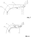
Fig. 7 , a section of thespray pipe 3 is disposed outside of thedetergent tank 6 and integrated with the detergent tank, and part of the wall of the spray pipe is integrated with the housing of thedetergent tank 3. The channel 7 is formed by means of a structure that avent hole 71 is opened on the part of the wall of the spray pipe integrated with the housing of thedetergent tank 3. After the washing procedure, thesolenoid valve 2 is opened, and the inside of the drum, as well as the viewing window are rinsed by the sprayed water. During the spray process, on one hand, a small part of water flows to thedetergent tank 6 via thevent hole 71, and eventually flows into the drum, on the other hand most water flows from thespray pipe 3 to thespray device 4 for spray. When the spray step finishes and thesolenoid valve 2 is closed, the interior of thespray pipe 3 is communicated with thedetergent tank 6 via the channel, so that the pressure is balanced due to the fact that thedetergent tank 6 is communicated with the atmosphere, and then the residual water flows out from the spray pipe. - As shown in
Fig. 8 , a section of thespray pipe 3 is disposed outside of the housing of thedetergent tank 6 and is integrated with thedetergent tank 6, and a part of the pipe wall of thespray pipe 3 is integrated with the housing of thedetergent tank 6. The channel 7 is formed by means of a one-way valve arranged on the part of the spray pipe wall integrated with the detergent tank housing, the end P of the one-way valve is arranged facing the interior of the housing of thedetergent tank 6 and the end A is arranged facing the pipe wall of the spray pipe. After the washing procedure, thesolenoid valve 2 is opened, and the inside of the drum, as well as the viewing window are rinsed by the sprayed water, force due to water flow exerts on the one-way valve port to close it, further shut off the air flow between the end A and the end P; when the spray step finishes and thesolenoid valve 2 is closed, the interior pressure of thespray pipe 3 drops so that the valve port of the one-way valve 7 is opened, air flows from the end P to the end A, and eventually flows into thespray pipe 3. Accordingly, the interior pressure of thespray pipe 3 and the exterior pressure outside the pipe end are balanced, so that the residual water in thespray pipe 3 could be drained out. - As shown in
Fig. 9 , a section of thespray pipe 3 is disposed inside of the housing of thedetergent tank 6 and is integrated with thedetergent tank 6, and a part of the pipe wall of thespray pipe 3 is integrated with the housing of thedetergent tank 6. The channel 7 is formed by means of a one-way valve arranged on the non-integrated part of the pipe wall of thespray pipe 3 away from the housing of thedetergent tank 6, and the end A is arranged facing the spray pipe wall. After the washing procedure, thesolenoid valve 2 is opened, and the inside of the drum, as well as the viewing window are rinsed by the sprayed water, force due to water flow exerts on the one-way valve port to close it, further shut off the air flow between the end A and the end P; when the spray step finishes and thesolenoid valve 2 is closed, the interior pressure of thespray pipe 3 drops so that the valve port of the one-way valve 7 is opened, air flows from the end P to the end A, and eventually flows into thespray pipe 3. Accordingly, the interior pressure of thespray pipe 3 and the exterior pressure outside the pipe end are balanced, so that the residual water in thespray pipe 3 could be drained out. - As shown in
Fig. 10 , a section of thespray pipe 3 is disposed inside of the housing of thedetergent tank 6 and is integrated with thedetergent tank 6, and a part of the pipe wall of thespray pipe 3 is integrated with the housing of thedetergent tank 6, and the channel 7 is formed by the structure that avent hole 71 is opened on the non-integrated part of the pipe wall of thespray pipe 3 away from the housing of thedetergent tank 6. After the washing procedure, thesolenoid valve 2 is opened, and the inside of the drum, as well as the viewing window are rinsed by the sprayed water. During the spray process, on one hand, a small part of water flows to thedetergent tank 6 through thevent hole 71, and eventually flows into the drum, on the other hand most water flows from thespray pipe 3 to thespray device 4 for spray. When the spray step finishes and thesolenoid valve 2 is closed, the interior of thespray pipe 3 is communicated with thedetergent tank 6 via the channel, so that the pressure is balanced due to the fact that thedetergent tank 6 is communicated with the atmosphere, and then the residual water flows out from the spray pipe. - Based on the embodiments illustrated in
Fig. 9 and Fig. 10 , as well as the status as shown in theFig. 11 , it is featured that a section of thespray pipe 3 passes through the housing of thedetergent tank 6 and is integrated with the housing where the channel is formed by means of a one-way valve disposed inside the housing of the detergent tank, or by means of a vent hole opened inside the housing of thedetergent tank 6. - In the embodiments, one or more vent holes or one or more one-way valves could be provided.
- The present invention also provides a drum washing machine comprising any of the devices for preventing water leakage of spray pipe in drum washing machine as described in various embodiments above.
- According to the embodiments of the present invention, a device for preventing water leakage of spray pipe in the drum washing machine and a drum washing machine comprises the same are provided. The device provides a channel between the spray pipe of the drum washing machine and the detergent tank communicating with the atmosphere so that the spray pipe is communicated with the atmosphere as well. After the washing procedure, the solenoid valve is closed and the spray pipe is communicated with the atmosphere via the channel so that the residual water in the spray pipe suffers atmosphere and flows out. The next time when users open the door, there will be no water leaking out on the floor because no water residing in the spray pipe, thereby enhancing user experience.
- It should be noted that the foregoing description is not to be construed as limitation of the invention. The invention also should not be limited is the above-described embodiments. Changes, modifications, additions or substitutions made by one of ordinary skill in the art should be regarded within the spirit and scope of the invention.
Claims (10)
- A device for preventing water leakage at end of the spray pipe in drum washing machine, including a faucet, a water inlet valve, a spray pipe, a detergent tank and a spray device, wherein the water inlet valve is connected to the faucet; the water inlet valve is provided with a solenoid valve; the water inlet end of the spray pipe is connected to the solenoid valve; the water outlet end of the spray pipe is connected to the spray device; and the spray pipe and the detergent tank are connected by means of a channel.
- The device for preventing water leakage at end of the spray pipe in drum washing machine according to claim 1, wherein a section of the spray pipe is disposed outside the housing of the detergent tank; and the channel is formed by means of a one-way valve mounted between the spray pipe and the housing of the detergent tank.
- The device for preventing water leakage at end of the spray pipe in drum washing machine according to claim 1, wherein a section of the spray pipe is disposed outside the housing of the detergent tank; and the channel is formed by means of a structure that the wall of the spray pipe is connecting to a vent hole opened on the housing of the detergent tank through a branch pipe.
- The device for preventing water leakage at end of the spray pipe in drum washing machine according to claim 1, wherein the spray pipe passes through the inside of the detergent tank; and the channel is formed by a one-way valve mounted on the part of the spray pipe wall inside the detergent tank.
- The device for preventing water leakage at end of the spray pipe in drum washing machine according to claim 1, wherein the spray pipe passes through the inside of the detergent tank; and the channel is formed by means of a vent hole opened on the part of the spray pipe wall inside the detergent tank.
- The device for preventing water leakage at end of the spray pipe in drum washing machine according to claim 1, wherein a section of the spray pipe disposed outside of the detergent tank housing; and a section of the spray pipe wall is integrated with the detergent tank housing; the channel is formed by a vent hole opened on the section of the spray pipe wall integrated with the detergent tank housing.
- The device for preventing water leakage at end of the spray pipe in drum washing machine according to claim 1, wherein a section of the spray pipe disposed outside of the detergent tank housing; and a section of the spray pipe wall is integrated with the detergent tank housing; the channel is formed by a one-way valve arranged on the section of the spray pipe wall integrated with the detergent tank housing.
- The device for preventing water leakage at end of the spray pipe in drum washing machine according to claim 1, wherein a section of the spray pipe disposed inside of the detergent tank housing; and a section of the spray pipe wall is integrated with the detergent tank housing; the channel is formed by a one-way valve arranged on the non-integrated section of the spray pipe wall away from the detergent tank housing.
- The device for preventing water leakage at end of the spray pipe in drum washing machine according to claim 1, wherein a section of the spray pipe disposed inside of the detergent tank housing; and a section of the spray pipe wall is integrated with the detergent tank housing; the channel is formed by a vent hole opened on the non-integrated section of the spray pipe wall away from the detergent tank housing.
- A drum washing machine, including the device for preventing water leakage at end of the spray pipe in drum washing machine according to any one of claim 1 to claim 9.
Applications Claiming Priority (2)
| Application Number | Priority Date | Filing Date | Title |
|---|---|---|---|
| CN201510177345.9A CN106149308B (en) | 2015-04-15 | 2015-04-15 | The device and roller washing machine for preventing roller washing machine spray nozzle from dripping |
| PCT/CN2016/077491 WO2016165552A1 (en) | 2015-04-15 | 2016-03-28 | Device for preventing spray pipe orifice of roller washing machine from dripping water, and roller washing machine |
Publications (2)
| Publication Number | Publication Date |
|---|---|
| EP3284855A1 true EP3284855A1 (en) | 2018-02-21 |
| EP3284855A4 EP3284855A4 (en) | 2018-12-26 |
Family
ID=57126394
Family Applications (1)
| Application Number | Title | Priority Date | Filing Date |
|---|---|---|---|
| EP16779527.7A Withdrawn EP3284855A4 (en) | 2015-04-15 | 2016-03-28 | Device for preventing spray pipe orifice of roller washing machine from dripping water, and roller washing machine |
Country Status (4)
| Country | Link |
|---|---|
| EP (1) | EP3284855A4 (en) |
| KR (1) | KR20170137892A (en) |
| CN (1) | CN106149308B (en) |
| WO (1) | WO2016165552A1 (en) |
Cited By (3)
| Publication number | Priority date | Publication date | Assignee | Title |
|---|---|---|---|---|
| CN111334980A (en) * | 2018-12-19 | 2020-06-26 | 青岛海尔滚筒洗衣机有限公司 | Air washing device for laundry treatment equipment and laundry treatment equipment |
| JP2022512296A (en) * | 2018-12-19 | 2022-02-03 | 青島海爾▲滾▼筒洗衣机有限公司 | Air wash equipment and garment processing equipment for garment processing equipment |
| EP3901351A4 (en) * | 2018-12-19 | 2022-03-23 | Qingdao Haier Drum Washing Machine Co., Ltd. | Laundry treatment apparatus |
Families Citing this family (12)
| Publication number | Priority date | Publication date | Assignee | Title |
|---|---|---|---|---|
| CN107119423B (en) * | 2017-03-30 | 2021-10-22 | 青岛海尔洗涤电器有限公司 | A washing machine door end spray device, working method and washing machine |
| CN108729141A (en) * | 2017-04-17 | 2018-11-02 | 青岛海尔滚筒洗衣机有限公司 | A kind of detergent launches structure and washing machine |
| CN107090697A (en) * | 2017-04-19 | 2017-08-25 | 青岛海尔滚筒洗衣机有限公司 | A kind of washing machine inflow control method and washing machine |
| CN107164920B (en) * | 2017-06-14 | 2024-10-29 | 天津海尔洗涤电器有限公司 | Washing machine water storage tank and washing machine |
| CN109402963B (en) * | 2017-08-17 | 2024-02-09 | 上海小吉互联网科技有限公司 | Automatic detergent throwing device of washing machine |
| JP2022514764A (en) * | 2018-12-19 | 2022-02-15 | 青島海爾▲滾▼筒洗衣机有限公司 | Clothes processing equipment |
| CN111334988B (en) * | 2018-12-19 | 2023-05-26 | 青岛海尔洗涤电器有限公司 | Clothes treating apparatus |
| CN111719288A (en) * | 2019-03-04 | 2020-09-29 | 青岛海尔洗衣机有限公司 | Laundry washing equipment with internal circulation function |
| CN112709052B (en) * | 2019-10-25 | 2024-05-31 | 青岛海尔洗涤电器有限公司 | Drum washing machine and control method thereof |
| CN112900018B (en) * | 2019-11-19 | 2024-05-28 | 重庆海尔滚筒洗衣机有限公司 | Water inlet control method for clothing processing equipment and clothing processing equipment |
| CN115613284B (en) * | 2022-09-26 | 2025-11-28 | 珠海格力电器股份有限公司 | Runner plate and washing machine |
| CN121951875A (en) * | 2024-10-31 | 2026-05-01 | 青岛海尔洗衣机有限公司 | A garment processing device and its control method |
Family Cites Families (8)
| Publication number | Priority date | Publication date | Assignee | Title |
|---|---|---|---|---|
| IT1259234B (en) * | 1992-11-11 | 1996-03-11 | Zanussi Elettrodomestici | WASHING MACHINES WITH A PERFECTED WATER FILLING DEVICE |
| JPH09308796A (en) * | 1996-05-23 | 1997-12-02 | Sanyo Electric Co Ltd | Washing machine |
| CN201037211Y (en) * | 2007-04-13 | 2008-03-19 | 松下电化住宅设备机器(杭州)有限公司 | Drum-type washing machine |
| KR101128809B1 (en) * | 2008-12-29 | 2012-03-23 | 엘지전자 주식회사 | A Washing Machine |
| KR101635873B1 (en) * | 2009-09-04 | 2016-07-20 | 엘지전자 주식회사 | Laundry machine |
| CN201762574U (en) * | 2009-10-30 | 2011-03-16 | 王焕江 | Rolling washing machine |
| JP2013009810A (en) * | 2011-06-29 | 2013-01-17 | Panasonic Corp | Drum type washer |
| WO2013091288A1 (en) * | 2011-12-19 | 2013-06-27 | 海尔集团公司 | Device and method for cleaning observation window and window spacer sealing ring, and washing machine applying the same |
-
2015
- 2015-04-15 CN CN201510177345.9A patent/CN106149308B/en active Active
-
2016
- 2016-03-28 WO PCT/CN2016/077491 patent/WO2016165552A1/en not_active Ceased
- 2016-03-28 KR KR1020177033095A patent/KR20170137892A/en not_active Ceased
- 2016-03-28 EP EP16779527.7A patent/EP3284855A4/en not_active Withdrawn
Cited By (3)
| Publication number | Priority date | Publication date | Assignee | Title |
|---|---|---|---|---|
| CN111334980A (en) * | 2018-12-19 | 2020-06-26 | 青岛海尔滚筒洗衣机有限公司 | Air washing device for laundry treatment equipment and laundry treatment equipment |
| JP2022512296A (en) * | 2018-12-19 | 2022-02-03 | 青島海爾▲滾▼筒洗衣机有限公司 | Air wash equipment and garment processing equipment for garment processing equipment |
| EP3901351A4 (en) * | 2018-12-19 | 2022-03-23 | Qingdao Haier Drum Washing Machine Co., Ltd. | Laundry treatment apparatus |
Also Published As
| Publication number | Publication date |
|---|---|
| WO2016165552A1 (en) | 2016-10-20 |
| CN106149308B (en) | 2019-06-28 |
| EP3284855A4 (en) | 2018-12-26 |
| KR20170137892A (en) | 2017-12-13 |
| CN106149308A (en) | 2016-11-23 |
Similar Documents
| Publication | Publication Date | Title |
|---|---|---|
| CN106149308B (en) | The device and roller washing machine for preventing roller washing machine spray nozzle from dripping | |
| KR101748474B1 (en) | Spraying washing device of drum washing machine, washing method thereof and the drum washing machine | |
| CN201074281Y (en) | Barrel washing machine | |
| CN106555299B (en) | A kind of spray system and washing machine of washing machine | |
| CN104545751B (en) | The ventilative of water tank cleaner, spilling water protection and cleaning agent adding set | |
| CN107164920B (en) | Washing machine water storage tank and washing machine | |
| JP2019517365A (en) | Drum type washing machine and washing method thereof | |
| CN111334964B (en) | Clothes processing equipment | |
| US7426932B2 (en) | Spray fill device and method for using the same | |
| CN107119423A (en) | A kind of door of washing machine end spray equipment, method of work and washing machine | |
| CN104109965B (en) | Washing machine detergent dissolves foaming mechanisms and its washing machine | |
| CN110387707B (en) | Roller washing machine and door body and spraying system thereof | |
| WO2019214517A1 (en) | Drum washing machine and spraying system thereof | |
| WO2019201119A1 (en) | Front-loading washer and spray system thereof | |
| CN107090697A (en) | A kind of washing machine inflow control method and washing machine | |
| WO2018121260A1 (en) | Laundry detergent supplying device and washing machine | |
| CN209953422U (en) | Quantitative nano atomization medicine supply pipeline automatic cleaning system | |
| CN112709052B (en) | Drum washing machine and control method thereof | |
| CN110387699B (en) | Front-loading washing machine and its spray system | |
| CN101629373A (en) | Sterilizing and cleaning device for washing machine, washing machine provided with same as well as sterilizing and cleaning method for washing machine | |
| KR20190075618A (en) | Dish Washer | |
| CN118127755A (en) | Isolation washing control method for washing equipment | |
| CN203947333U (en) | Washing machine detergent dissolving and foaming mechanism and its washing machine | |
| CN110387706B (en) | Roller washing machine and spraying system thereof | |
| KR102518818B1 (en) | Detergent supply device for washing machine |
Legal Events
| Date | Code | Title | Description |
|---|---|---|---|
| PUAI | Public reference made under article 153(3) epc to a published international application that has entered the european phase |
Free format text: ORIGINAL CODE: 0009012 |
|
| 17P | Request for examination filed |
Effective date: 20171114 |
|
| AK | Designated contracting states |
Kind code of ref document: A1 Designated state(s): AL AT BE BG CH CY CZ DE DK EE ES FI FR GB GR HR HU IE IS IT LI LT LU LV MC MK MT NL NO PL PT RO RS SE SI SK SM TR |
|
| AX | Request for extension of the european patent |
Extension state: BA ME |
|
| DAV | Request for validation of the european patent (deleted) | ||
| DAX | Request for extension of the european patent (deleted) | ||
| A4 | Supplementary search report drawn up and despatched |
Effective date: 20181128 |
|
| RIC1 | Information provided on ipc code assigned before grant |
Ipc: D06F 35/00 20060101ALN20181121BHEP Ipc: D06F 39/08 20060101AFI20181121BHEP |
|
| STAA | Information on the status of an ep patent application or granted ep patent |
Free format text: STATUS: THE APPLICATION IS DEEMED TO BE WITHDRAWN |
|
| 18D | Application deemed to be withdrawn |
Effective date: 20190625 |