EP3283925B1 - Verfahren und vorrichtung zum herstellen eines volumenhologramms in einem fotopolymermaterial sowie verfahren zum herstellen eines wert- oder sicherheitsdokuments - Google Patents
Verfahren und vorrichtung zum herstellen eines volumenhologramms in einem fotopolymermaterial sowie verfahren zum herstellen eines wert- oder sicherheitsdokuments Download PDFInfo
- Publication number
- EP3283925B1 EP3283925B1 EP16717608.0A EP16717608A EP3283925B1 EP 3283925 B1 EP3283925 B1 EP 3283925B1 EP 16717608 A EP16717608 A EP 16717608A EP 3283925 B1 EP3283925 B1 EP 3283925B1
- Authority
- EP
- European Patent Office
- Prior art keywords
- photopolymer material
- photopolymer
- nir
- volume hologram
- exposure
- Prior art date
- Legal status (The legal status is an assumption and is not a legal conclusion. Google has not performed a legal analysis and makes no representation as to the accuracy of the status listed.)
- Active
Links
Images


Classifications
-
- G—PHYSICS
- G03—PHOTOGRAPHY; CINEMATOGRAPHY; ANALOGOUS TECHNIQUES USING WAVES OTHER THAN OPTICAL WAVES; ELECTROGRAPHY; HOLOGRAPHY
- G03H—HOLOGRAPHIC PROCESSES OR APPARATUS
- G03H1/00—Holographic processes or apparatus using light, infrared or ultraviolet waves for obtaining holograms or for obtaining an image from them; Details peculiar thereto
- G03H1/04—Processes or apparatus for producing holograms
- G03H1/18—Particular processing of hologram record carriers, e.g. for obtaining blazed holograms
- G03H1/182—Post-exposure processing, e.g. latensification
-
- B—PERFORMING OPERATIONS; TRANSPORTING
- B32—LAYERED PRODUCTS
- B32B—LAYERED PRODUCTS, i.e. PRODUCTS BUILT-UP OF STRATA OF FLAT OR NON-FLAT, e.g. CELLULAR OR HONEYCOMB, FORM
- B32B37/00—Methods or apparatus for laminating, e.g. by curing or by ultrasonic bonding
- B32B37/06—Methods or apparatus for laminating, e.g. by curing or by ultrasonic bonding characterised by the heating method
-
- B—PERFORMING OPERATIONS; TRANSPORTING
- B42—BOOKBINDING; ALBUMS; FILES; SPECIAL PRINTED MATTER
- B42D—BOOKS; BOOK COVERS; LOOSE LEAVES; PRINTED MATTER CHARACTERISED BY IDENTIFICATION OR SECURITY FEATURES; PRINTED MATTER OF SPECIAL FORMAT OR STYLE NOT OTHERWISE PROVIDED FOR; DEVICES FOR USE THEREWITH AND NOT OTHERWISE PROVIDED FOR; MOVABLE-STRIP WRITING OR READING APPARATUS
- B42D25/00—Information-bearing cards or sheet-like structures characterised by identification or security features; Manufacture thereof
- B42D25/30—Identification or security features, e.g. for preventing forgery
- B42D25/328—Diffraction gratings; Holograms
-
- B—PERFORMING OPERATIONS; TRANSPORTING
- B65—CONVEYING; PACKING; STORING; HANDLING THIN OR FILAMENTARY MATERIAL
- B65H—HANDLING THIN OR FILAMENTARY MATERIAL, e.g. SHEETS, WEBS, CABLES
- B65H20/00—Advancing webs
- B65H20/24—Advancing webs by looping or like devices
-
- F—MECHANICAL ENGINEERING; LIGHTING; HEATING; WEAPONS; BLASTING
- F26—DRYING
- F26B—DRYING SOLID MATERIALS OR OBJECTS BY REMOVING LIQUID THEREFROM
- F26B3/00—Drying solid materials or objects by processes involving the application of heat
- F26B3/28—Drying solid materials or objects by processes involving the application of heat by radiation, e.g. from the sun
- F26B3/30—Drying solid materials or objects by processes involving the application of heat by radiation, e.g. from the sun from infrared-emitting elements
-
- G—PHYSICS
- G03—PHOTOGRAPHY; CINEMATOGRAPHY; ANALOGOUS TECHNIQUES USING WAVES OTHER THAN OPTICAL WAVES; ELECTROGRAPHY; HOLOGRAPHY
- G03D—APPARATUS FOR PROCESSING EXPOSED PHOTOGRAPHIC MATERIALS; ACCESSORIES THEREFOR
- G03D13/00—Processing apparatus or accessories therefor, not covered by groups G11B3/00 - G11B11/00
- G03D13/002—Heat development apparatus, e.g. Kalvar
-
- G—PHYSICS
- G11—INFORMATION STORAGE
- G11B—INFORMATION STORAGE BASED ON RELATIVE MOVEMENT BETWEEN RECORD CARRIER AND TRANSDUCER
- G11B7/00—Recording or reproducing by optical means, e.g. recording using a thermal beam of optical radiation by modifying optical properties or the physical structure, reproducing using an optical beam at lower power by sensing optical properties; Record carriers therefor
- G11B7/24—Record carriers characterised by shape, structure or physical properties, or by the selection of the material
- G11B7/2403—Layers; Shape, structure or physical properties thereof
- G11B7/24035—Recording layers
- G11B7/24044—Recording layers for storing optical interference patterns, e.g. holograms; for storing data in three dimensions [3D], e.g. volume storage
-
- G—PHYSICS
- G11—INFORMATION STORAGE
- G11B—INFORMATION STORAGE BASED ON RELATIVE MOVEMENT BETWEEN RECORD CARRIER AND TRANSDUCER
- G11B7/00—Recording or reproducing by optical means, e.g. recording using a thermal beam of optical radiation by modifying optical properties or the physical structure, reproducing using an optical beam at lower power by sensing optical properties; Record carriers therefor
- G11B7/24—Record carriers characterised by shape, structure or physical properties, or by the selection of the material
- G11B7/241—Record carriers characterised by shape, structure or physical properties, or by the selection of the material characterised by the selection of the material
- G11B7/242—Record carriers characterised by shape, structure or physical properties, or by the selection of the material characterised by the selection of the material of recording layers
- G11B7/244—Record carriers characterised by shape, structure or physical properties, or by the selection of the material characterised by the selection of the material of recording layers comprising organic materials only
- G11B7/245—Record carriers characterised by shape, structure or physical properties, or by the selection of the material characterised by the selection of the material of recording layers comprising organic materials only containing a polymeric component
-
- B—PERFORMING OPERATIONS; TRANSPORTING
- B32—LAYERED PRODUCTS
- B32B—LAYERED PRODUCTS, i.e. PRODUCTS BUILT-UP OF STRATA OF FLAT OR NON-FLAT, e.g. CELLULAR OR HONEYCOMB, FORM
- B32B2309/00—Parameters for the laminating or treatment process; Apparatus details
- B32B2309/02—Temperature
-
- B—PERFORMING OPERATIONS; TRANSPORTING
- B32—LAYERED PRODUCTS
- B32B—LAYERED PRODUCTS, i.e. PRODUCTS BUILT-UP OF STRATA OF FLAT OR NON-FLAT, e.g. CELLULAR OR HONEYCOMB, FORM
- B32B2310/00—Treatment by energy or chemical effects
- B32B2310/08—Treatment by energy or chemical effects by wave energy or particle radiation
- B32B2310/0806—Treatment by energy or chemical effects by wave energy or particle radiation using electromagnetic radiation
- B32B2310/0825—Treatment by energy or chemical effects by wave energy or particle radiation using electromagnetic radiation using IR radiation
-
- B—PERFORMING OPERATIONS; TRANSPORTING
- B32—LAYERED PRODUCTS
- B32B—LAYERED PRODUCTS, i.e. PRODUCTS BUILT-UP OF STRATA OF FLAT OR NON-FLAT, e.g. CELLULAR OR HONEYCOMB, FORM
- B32B2425/00—Cards, e.g. identity cards, credit cards
-
- B—PERFORMING OPERATIONS; TRANSPORTING
- B32—LAYERED PRODUCTS
- B32B—LAYERED PRODUCTS, i.e. PRODUCTS BUILT-UP OF STRATA OF FLAT OR NON-FLAT, e.g. CELLULAR OR HONEYCOMB, FORM
- B32B37/00—Methods or apparatus for laminating, e.g. by curing or by ultrasonic bonding
- B32B37/0046—Methods or apparatus for laminating, e.g. by curing or by ultrasonic bonding characterised by constructional aspects of the apparatus
- B32B37/0053—Constructional details of laminating machines comprising rollers; Constructional features of the rollers
-
- B—PERFORMING OPERATIONS; TRANSPORTING
- B65—CONVEYING; PACKING; STORING; HANDLING THIN OR FILAMENTARY MATERIAL
- B65H—HANDLING THIN OR FILAMENTARY MATERIAL, e.g. SHEETS, WEBS, CABLES
- B65H2557/00—Means for control not provided for in groups B65H2551/00 - B65H2555/00
- B65H2557/50—Use of particular electromagnetic waves, e.g. light, radiowaves or microwaves
- B65H2557/514—Use of particular electromagnetic waves, e.g. light, radiowaves or microwaves ultraviolet
-
- B—PERFORMING OPERATIONS; TRANSPORTING
- B65—CONVEYING; PACKING; STORING; HANDLING THIN OR FILAMENTARY MATERIAL
- B65H—HANDLING THIN OR FILAMENTARY MATERIAL, e.g. SHEETS, WEBS, CABLES
- B65H2701/00—Handled material; Storage means
- B65H2701/10—Handled articles or webs
- B65H2701/17—Nature of material
- B65H2701/175—Plastic
- B65H2701/1752—Polymer film
-
- G—PHYSICS
- G03—PHOTOGRAPHY; CINEMATOGRAPHY; ANALOGOUS TECHNIQUES USING WAVES OTHER THAN OPTICAL WAVES; ELECTROGRAPHY; HOLOGRAPHY
- G03H—HOLOGRAPHIC PROCESSES OR APPARATUS
- G03H1/00—Holographic processes or apparatus using light, infrared or ultraviolet waves for obtaining holograms or for obtaining an image from them; Details peculiar thereto
- G03H1/0005—Adaptation of holography to specific applications
- G03H1/0011—Adaptation of holography to specific applications for security or authentication
-
- G—PHYSICS
- G03—PHOTOGRAPHY; CINEMATOGRAPHY; ANALOGOUS TECHNIQUES USING WAVES OTHER THAN OPTICAL WAVES; ELECTROGRAPHY; HOLOGRAPHY
- G03H—HOLOGRAPHIC PROCESSES OR APPARATUS
- G03H1/00—Holographic processes or apparatus using light, infrared or ultraviolet waves for obtaining holograms or for obtaining an image from them; Details peculiar thereto
- G03H1/02—Details of features involved during the holographic process; Replication of holograms without interference recording
- G03H1/024—Hologram nature or properties
- G03H1/0248—Volume holograms
-
- G—PHYSICS
- G03—PHOTOGRAPHY; CINEMATOGRAPHY; ANALOGOUS TECHNIQUES USING WAVES OTHER THAN OPTICAL WAVES; ELECTROGRAPHY; HOLOGRAPHY
- G03H—HOLOGRAPHIC PROCESSES OR APPARATUS
- G03H1/00—Holographic processes or apparatus using light, infrared or ultraviolet waves for obtaining holograms or for obtaining an image from them; Details peculiar thereto
- G03H1/04—Processes or apparatus for producing holograms
- G03H1/18—Particular processing of hologram record carriers, e.g. for obtaining blazed holograms
- G03H2001/185—Applying a curing step
-
- G—PHYSICS
- G03—PHOTOGRAPHY; CINEMATOGRAPHY; ANALOGOUS TECHNIQUES USING WAVES OTHER THAN OPTICAL WAVES; ELECTROGRAPHY; HOLOGRAPHY
- G03H—HOLOGRAPHIC PROCESSES OR APPARATUS
- G03H2227/00—Mechanical components or mechanical aspects not otherwise provided for
- G03H2227/04—Production line for mass production
-
- G—PHYSICS
- G03—PHOTOGRAPHY; CINEMATOGRAPHY; ANALOGOUS TECHNIQUES USING WAVES OTHER THAN OPTICAL WAVES; ELECTROGRAPHY; HOLOGRAPHY
- G03H—HOLOGRAPHIC PROCESSES OR APPARATUS
- G03H2250/00—Laminate comprising a hologram layer
- G03H2250/10—Laminate comprising a hologram layer arranged to be transferred onto a carrier body
-
- G—PHYSICS
- G03—PHOTOGRAPHY; CINEMATOGRAPHY; ANALOGOUS TECHNIQUES USING WAVES OTHER THAN OPTICAL WAVES; ELECTROGRAPHY; HOLOGRAPHY
- G03H—HOLOGRAPHIC PROCESSES OR APPARATUS
- G03H2260/00—Recording materials or recording processes
- G03H2260/12—Photopolymer
Definitions
- the present invention relates to a method for producing a volume hologram in a photopolymer material, also a device for producing the volume hologram, the device being designed in particular to carry out the method according to the invention for producing the volume hologram, and a method for producing a value or security document, which has a volume hologram and in which the method for producing the volume hologram is applied.
- Valuable or security documents are used to verify the identity of a person, for example when crossing a national border, or the identity or thing or a claim, for example for payment of a sum of money or for the release of a product or the provision of a service. To this end, it must be ensured that the product cannot be imitated, counterfeited or falsified, or only with considerable effort.
- the document therefore contains security features which are extremely difficult or even practically impossible to imitate. For example, like banknotes, the document is made of a material that is not readily available.
- security features can be formed by special colors, for example luminescent or optically variable colors, optical security elements such as holograms, tilting images, kinegraphic objects, lens or prism arrays, also guilloches, mottled fibers, security threads and others. Furthermore, it is also necessary for the value or security documents to be easy to produce.
- Optical security elements can be produced separately, for example, and then glued as patches, security threads, security strips or the like to an external surface on the value or security document or to an internal surface in the value or security document.
- Such security elements can be optical be variable elements, so that visually perceptible phenomena generated therewith are either recognizable and/or can assume different shapes, depending on the angle at which the value or security document is viewed.
- These include surface and volume holograms. For example, results from DE 10 2009 007 552 A1 that value or security documents can be provided, for example, with a holographic, in particular volume holographic, security feature produced.
- Volume holograms can be used, among other things, to produce three-dimensional holographic disk systems that serve as storage and correlation devices with a high storage density and correlation rate.
- the photopolymer HRF-150 manufactured by DuPont is used, which is suitable for the production of transmission holograms with high resolution.
- the holograms are recorded with blue-green light.
- a 38 ⁇ m thick photopolymer film was sandwiched between two Mylar® (trademark of DuPont Teijin Film, US) sheets and exposed with a hologram generating device. After exposure, the hologram is fixed by exposure to UV radiation.
- Mylar® trademark of DuPont Teijin Film, US
- DE 10 2006 023 159 A1 describes a manufacturing process for documents with a hologram, in which, in a first step, a hologram is exposed and fixed in a photo film and, in a second step, the photo film is glued to a document carrier. For fixation, the photo film is fixed by irradiating it with UV light and then drying it in a dryer.
- DE 10 2007 019 837 A1 describes a method for generating the individual holographic personal information of a volume hologram, in which a photopolymer film is used, which is laminated to a holographic master and then all standard optical elements of the master are copied into the film with laser light.
- the exposed photopolymer film is developed in the usual way, namely fixed with UV light and baked at higher temperatures, preferably at 120.degree.
- U.S. 5,774,240 A discloses that a hologram recording disk is irradiated with an infrared generating device.
- U.S. 6,401,360 B1 discloses photo processing and, more particularly, an apparatus and method for drying photosensitive material.
- EP 0 962 822 A1 also discloses photo processing and an apparatus and method for drying photosensitive material.
- the EP 0 754 987 A2 discloses an article disc for recording holograms by exposure, a hologram manufacturing method and a hologram recorded article.
- volume hologram in which the volume of the recording material (a photopolymer material or laminate) is used to store the holographic image.
- the thickness of the recording material is in the order of the wavelength of the electromagnetic radiation used for recording, ie only slightly larger or even smaller than the wavelength of the radiation, even though the preferred application of the present invention relates to such recording materials refers, the thickness of which is substantially greater than the wavelength of the radiation, for example at least greater than twice the wavelength.
- the thickness of the recording material is limited to large thicknesses by desired physical properties and economics.
- the volume hologram can be a transmission hologram or a reflection hologram.
- the term 'value or security document' includes, for example, a passport, identity card, driver's license, access control card or other ID card, vehicle registration document, vehicle registration document, visa, cheque, Means of payment, in particular a bank note, a check, bank, credit or cash payment card, customer card, health card, chip card, company ID card, proof of entitlement, membership card, gift or shopping voucher, bill of lading or other proof of entitlement, tax stamp, postage stamp, ticket, token or understand another document.
- the value or security document can also be a smart card, for example.
- the value or security document can be in ID 1, ID 2, ID 3 or in any other standardized or non-standard format, for example in booklet form, like a passport-like object, or for example in card form.
- a valuable or security document is generally a laminate made up of several document layers which are connected to one another in a precise register under the action of heat and increased pressure. These documents should meet the standardized requirements, for example according to ISO 10373, ISO/IEC 7810, ISO 14443 in the version valid at the time of the priority of the present application.
- the document layers consist, for example, of a carrier material that is suitable for lamination.
- the value or security document can have further security features that are individualizing, in particular personalizing, or not individualizing. Guilloches, watermarks, embossed prints, a security thread, microwriting, tilting images, holograms, optically variable pigments, luminescent colors, transmitted light registers, mottled fibers and the like come into consideration as such security features.
- the document can also have electronic components, for example an RFID circuit with antenna and RFID microchip, electronic display elements, LEDs, touch-sensitive sensors and the like.
- the electronic components can be hidden between two opaque layers of the document.
- the value or security document can be formed from one or more polymers selected from a group comprising polycarbonate (PC), in particular bisphenol A polycarbonate, polyethylene terephthalate (PET), their derivatives, such as glycol-modified PET (PETG), Polyethylene naphthalate (PEN), Polyvinyl chloride (PVC), Polyvinyl butyral (PVB), Polymethyl methacrylate (PMMA), Polyimide (PI), Polyvinyl alcohol (PVA), Polystyrene (PS), Polyvinyl phenol (PVP), polypropylene (PP), polyethylene (PE), thermoplastic elastomers (TPE), in particular thermoplastic polyurethane (TPU), acrylonitrile butadiene styrene copolymer (ABS) and derivatives thereof, or paper or cardboard or glass or metal or pottery.
- PC polycarbonate
- PET polyethylene terephthalate
- PET polyethylene terephthalate
- their derivatives such as glycol-modified PET (PETG
- the document can also be made of several of these materials. It preferably consists of PC or PC/TPU/PC.
- the polymers can be either filled or unfilled. In the latter case, they are preferably transparent or translucent. If the polymers are filled, they are opaque.
- the document is preferably produced from 3 to 12, preferably 4 to 10 foils.
- the films can also carry printed layers.
- the present invention relates to a method for producing a volume hologram in a photopolymer material / a photopolymer layer according to claim 1.
- the method comprises, in a first method step, exposing the photopolymer material to an exposure pattern forming the volume hologram and, in a second method step, fixing the volume hologram by introducing thermal energy into the exposed photopolymer material so that the photopolymer material hardens.
- fixing can also include irradiation with electromagnetic radiation, in particular with UV radiation.
- this additional treatment can be carried out before the heat treatment.
- the UV treatment can lead to pre-polymerization of the exposed photopolymer material.
- UV treatment is required or not depends on the type of photopolymer material used.
- the subsequent heat treatment leads to the final polymerisation of the exposed photopolymer material.
- the thermal energy is introduced by irradiating electromagnetic radiation in the short-wave infrared spectral range.
- This electromagnetic radiation is in the near infrared range, particularly preferably in the wavelength range from 760 nm to 2000 nm (2 ⁇ m), most preferably in the wavelength range from 800 nm to 1200 nm (1.2 ⁇ m).
- the present invention relates to a method for producing a value or security document according to claim 7.
- the method comprises the production of a document blank and the application of a volume hologram to the document blank.
- the volume hologram is produced using the aforementioned production method according to the present invention.
- the present invention relates to a device for producing a volume hologram in a photopolymer material, in particular in a photopolymer layer, according to claim 8.
- This device is designed in particular for carrying out the method for producing a volume hologram in the photopolymer material according to the present invention.
- the device has an exposure device for exposing the photopolymer material with an exposure pattern forming the volume hologram and a fixing device for fixing the volume hologram by introducing thermal energy into the exposed photopolymer material.
- the fixing device has an NIR irradiation device (NIR: near infrared) in which the photopolymer material is exposed to electromagnetic radiation in the short-wave infrared spectral range, ie electromagnetic radiation in the near infrared range, particularly preferably in the wavelength range from 760 nm to 2000 nm and most preferably from 800 nm to 1200 nm.
- NIR near infrared
- the fixing device has at least two NIR emitters, which emit said electromagnetic radiation.
- the fixing device can also have a UV radiation device.
- Such a UV radiation device has at least one UV radiator that emits the UV radiation, for example radiation in the UVA spectral range (380 nm to 315 nm).
- the UV radiation device can be followed by the NIR radiation device in the direction of passage of the photopolymer material through the production device.
- the UV radiation device serves to pre-polymerize the exposed photopolymer material.
- the subsequent heat treatment in the NIR irradiation device leads to the final polymerisation of the exposed photopolymer material.
- the thermal treatment of the exposed photopolymer material with electromagnetic radiation in the short-wave infrared spectral range instead of a conventional treatment with warm air enables a thermal process to fix the hologram in the photopolymer material in a matter of seconds.
- This significant shortening of the processing time compared to conventional heat treatment is due to the properties of the photopolymer material, which absorb the electromagnetic radiation in the specified spectral range only slightly and thus practically uniformly in the entire volume of the photopolymer material.
- This behavior also applies to the usual use of a photopolymer laminate in which the photopolymer material is sandwiched between other polymeric films. As a result, the radiation can penetrate far into the material and is evenly absorbed in it.
- the invention thus results in many advantages over a conventional procedure for fixing the hologram produced by exposure, namely uniform and rapid polymerization of the exposed holographic material, uniform quality and appearance of the material surfaces, efficient baking of the holographic material, an increase in production through a optimized drying process, a reduction in energy and costs during drying (during fixing), maximum process reliability and the possibility of being able to easily integrate the concept according to the invention into existing and new devices for producing volume holograms.
- NIR band emitters are available for generating electromagnetic radiation in the short-wave infrared spectral range, which emit electromagnetic radiation, for example, with an emission maximum of 1200 nm.
- the radiation can be diffused or focused onto the photopolymer material by means of elliptical or parabolic reflectors.
- These NIR emitters can, in particular, be designed in the form of rods, so that, in conjunction with a parabolic reflector, a uniformly illuminated radiation field is generated, in which the photopolymer material is located during the irradiation.
- the electromagnetic NIR radiation is irradiated for a period of 0.5 min to 10 min, more preferably 0.75 min to 5 min and most preferably 1 min to 2 min.
- This period of time is sufficient to fix the hologram in the photopolymer material.
- This period of time is significantly shorter than the processing time required with some conventional drying methods, for example the processing time for hot air drying. In the latter case, it is generally necessary to treat the photopolymer material for a period of from 15 minutes to 20 minutes in order to achieve the desired polymerization of the material.
- the short fixation time with the method according to the invention enables a compact design of the fixation device and also only requires a small amount of energy.
- the photopolymer material is heated to a temperature of no more than 160° C., more preferably no more than 150° C. and most preferably no more than 120° C., by exposure to the electromagnetic NIR radiation , heated. This ensures gentle treatment of the photopolymer material. The volume heating of the material also prevents local temperature peaks from occurring in the material.
- the temperature of the photopolymer material is measured while the thermal energy is being introduced.
- the NIR irradiation device can additionally have temperature sensors. With this, it is possible to adjust the temperature in the photopolymer material within a narrow range.
- the power of an NIR emitter in the NIR irradiation device can be regulated as a function of the measured temperature in the photopolymer material. On the one hand, this allows the temperature to be set to a minimum value so that the hologram is fixed in the photopolymer material as quickly as possible, and on the other hand, a maximum temperature is not exceeded, which ensures that the photopolymer material is not thermally overloaded.
- the photopolymer material is exposed to laser radiation in the exposure device in order to produce the volume hologram. If a multicolored volume hologram is to be generated, laser radiation with different frequencies is used, for example by use of three laser devices that emit, for example, red or green or blue radiation.
- the photopolymer material is processed in a roll-to-roll process so that the manufacturing process can be carried out continuously.
- the photopolymer material is presented in the form of a strip and wound up on a feed roller.
- the feed roller forms a supply device for the fixing device with the band-shaped photopolymer material.
- the material is unwound from the roll and first reaches the exposure device, in which the material is exposed with the exposure pattern forming the volume hologram.
- the strip-shaped material then enters the fixing device, which has at least the NIR irradiation device.
- the photopolymer material is irradiated with electromagnetic radiation in the short-wave infrared spectral range.
- the fixing device also has the UV radiation device, with which the photopolymer material exposed in the exposure device is prepolymerized.
- the UV radiation device is preferably arranged in front of the NIR irradiation device in the direction of passage of the photopolymer material, so that the material first passes through the UV radiation device and only then through the NIR irradiation device. After the strip material has been processed in the fixing device, it arrives at a winding device, in which the material is wound onto a winding roll.
- the photopolymer material is passed through a first buffer device before exposure, in which the photopolymer material is temporarily stored in sections.
- This first buffer device is arranged before the exposure device in the direction of passage of the photopolymer material through the production device.
- the purpose of this is that the photopolymer material for exposure can be fixed in place in the exposure device in order to enable precise transfer of the exposure pattern forming the volume hologram onto the material. This requires an intermittent (clocked) transport of the photopolymer material through the exposure device. After exposing a portion of the web, the web is advanced in the exposure apparatus to allow a new portion to be exposed with another exposure pattern. Between these conveyance steps, the photopolymer material is in the exposure apparatus fixed and therefore immobile.
- the first buffer device buffers the intermittent movement in the exposure device. For this purpose, a section of the strip material is conveyed into the first buffer device during the period in which the strip material is held stationary in the exposure device and exposed, without being transported further to the exposure device. Only when the exposure is complete and the strip material is conveyed further in the exposure device is the strip material section conveyed into the first buffer device subsequently delivered to the exposure device.
- the photopolymer material is passed through a second buffer device after exposure and before the introduction of the thermal energy, in which the photopolymer material is temporarily stored in sections.
- the second buffer device is arranged after the exposure device and before the fixing device in the direction of passage of the photopolymer material through the production device.
- the intermittent movement of the web material is also buffered by the second buffering device when further conveyed from the exposure device to the fixing device. This also achieves continuous tape transport to the fixing device, while the tape material is moved intermittently in the exposure device.
- the thermal energy is radiated into the exposed photopolymer material from both sides.
- This achieves a very homogeneous introduction of the thermal energy into the photopolymer material.
- NIR emitters are arranged on both sides of the flow path for the strip-shaped photopolymer material, i.e. at least one NIR emitter in each case on each side of the photopolymer material.
- the thermal energy is introduced into the photopolymer material by means of one of the two NIR emitters that emit electromagnetic radiation, which is arranged on a first side of the photopolymer material, and after irradiating the photopolymer material at a reflector device, which is on a second side of the photopolymer material opposite the first side is arranged, reflected.
- a reflector device On a second side opposite the first A reflector device for the electromagnetic radiation emitted by the NIR irradiation device and radiated through the photopolymer material is therefore arranged on the side of the photopolymer material and is arranged opposite the NIR radiator.
- the NIR radiation device contains at least two NIR emitters according to the invention, which are arranged one behind the other along a flow path through the production device.
- the at least two NIR emitters in the NIR radiation device on one side of the flow path are each opposite a reflector device on the other side of the flow path, with the NIR emitters and the reflector devices on the respective sides alternating, i.e. one behind the other in the flow direction alternately, are arranged.
- the photopolymer material can be used in a conventional manner.
- the photopolymer material can be formed by a photopolymer layer in which the hologram is generated and which is located between a carrier film and a protective film. Together with these foils, the photopolymer layer forms a photopolymer laminate, which is processed in the production device.
- the photopolymer layer can have a thickness of 10 ⁇ m, for example, while the carrier film can have a thickness of 50 ⁇ m and the protective film can have a thickness of 21 ⁇ m. In principle, other thicknesses are also conceivable for these layers and foils.
- the carrier film and the protective film can be made of PET.
- the photopolymer laminate is in the form of a strip-like material (strip material), which is wound up on a feed roll, unwound from the feed roll and processed for processing (formation of the volume hologram) and wound up again on a take-up roll after processing.
- strip material strip material
- the carrier film is removed from the photopolymer material.
- An adhesive is preferably used to apply the hologram to the blank.
- the exposed and fixed photopolymer material can cover the value or security document over the whole area or only partially.
- the hologram may occupy part of the area occupied by the photopolymer material.
- the finished document preferably has a transparent protective layer over the applied material, which can be formed by a layer of lacquer.
- the hologram can be individualizing, i.e. the hologram can be assigned to a specific subject (person, animal, object) or forms a mark that uniquely identifies the document itself or a group of documents, or it can be personalizing, i.e. the hologram of a person is assignable. Or the hologram is not individualizing and only serves to verify the document. Accordingly, the hologram can show, for example, the passport photo of the person to whom the document is assigned, a serial number or a coat of arms.
- a document blank is first produced.
- the finished hologram is applied to this, for example glued on.
- the document blank can be produced in the usual way, for example by laminating polymer films, and, apart from the volume hologram, can already contain all or almost all other security features of the finished value or security document.
- a protective layer can finally be applied, which protects the hologram against damage and manipulation.
- a value or security document 100 in the form of an identity card is in 1 shown.
- This card preferably has the standardized dimensions in format ID 1 according to DIN/IEC 7810 in the version valid at the time of the priority of the present application.
- the card can be made in the form of a laminate based on PC and PET, which are partly opaque (inner layers) and partly transparent (outer layers). An internal electronic circuit can be shielded from view from the outside by means of inner opaque layers.
- the card has a front 101 and a back 102 (in 1 not shown).
- a facial image of the holder in the form of a passport photo 110 and data fields 120, 130 showing the holder's data and other data such as a serial number and the like are visible on the front.
- Also on the front is a hologram 200 formed in a photopolymer material (in 1 not shown).
- In 2 is the card 100 from 1 shown in a schematic sectional view, with the depiction of details of the card material below the exposed and fixed photopolymer material 310 being dispensed with, for example an electronic circuit located inside the card, such as an RFID circuit with an RFID chip and RFID antenna, and various layer structures .
- photopolymer material 310 On top of the blank card 150 is photopolymer material 310, which covers the entire surface of the blank, for example, is applied/glued on. Since the carrier film 320 and the protective film 330 of the photopolymer laminate 300 have been removed, only the exposed and fixed photopolymer layer (photopolymer material) remains on the card.
- a volume hologram 200 is exposed into this material using the method according to the invention and fixed therein ( 1 ).
- a protective layer 160 is additionally applied to the photopolymer layer, which can be formed from a transparent, colorless protective lacquer, for example.
- a photopolymer laminate 300 is shown in a schematic sectional view. This laminate is easy to handle, while the photopolymer material 310 is extremely delicate.
- the photopolymer layer 310 is sandwiched in the laminate between a bottom support sheet 320 and a top protective sheet 330 .
- the carrier film and the protective film are formed from PET, for example.
- the thickness of the carrier film is, for example, 50 ⁇ m, that of the protective film is 21 ⁇ m and that of the photopolymer layer is, for example, 10 ⁇ m.
- a device 1000 according to the invention for producing a volume hologram 200 in a photopolymer material 310, which is provided in the form of a photopolymer laminate 300, is shown schematically. It is a device in which a roll-to-roll process is carried out.
- a supply device 1100 with a feed roller 1110 with photopolymer material that has not yet been processed is provided for this purpose.
- the photopolymer laminate is wound up on the feed roll and can be made available by unwinding.
- a first buffer device 1200 Downstream of the supply device 1100 in the throughput direction R of the photopolymer laminate 300 in the production device 1000 is a first buffer device 1200. As shown, this device can contain three deflection rollers 1210, 1220, 1230, which guide the photopolymer laminate on a winding path D through this device. Of these pulleys, the top two pulleys 1210, 1220 are stationary in the apparatus, while the center lower pulley 1230 is vertically displaceable so that the length of the portion of the photopolymer laminate in the apparatus can vary.
- an exposure device 1300 Downstream of the first buffer device 1200 in the throughput direction R of the photopolymer laminate 300 in the production device 1000 is an exposure device 1300, with which the is exposed through this passing photopolymer laminate with the exposure pattern forming the volume hologram 200 .
- three laser devices 1310, 1320, 1330 are shown here, the laser beams of which are directed via deflection mirrors 1340, 1350, 1360 onto the photopolymer laminate or the photopolymer material 310 located therein. These three lasers emit laser light with different wavelengths, so a multicolored hologram can be created.
- the first laser device 1310 emits red laser radiation
- the laser beams are focused onto the photopolymer material using suitable optical means (not shown), so that even very small exposure structures can be produced. The optical elements required for this are not shown.
- a second buffer device 1400 Downstream of the exposure device 1300 in the throughput direction R of the photopolymer laminate 300 in the production device 1000 is a second buffer device 1400. Like the first buffer device 1200, this can also contain three deflection rollers 1410, 1420, 1430, as shown, which guide the photopolymer laminate on a winding path D through the guide device. Of these pulleys, the top two pulleys 1410, 1420 are stationary in the apparatus, while the center lower pulley 1430 is vertically displaceable so that the length of the portion of the photopolymer laminate in the apparatus can vary.
- the fixing device 1500 Downstream of the second buffer device 1400 in the throughput direction R of the photopolymer laminate 300 in the production device 1000 is the fixing device 1500.
- This has a UV radiation device 1510 and an NIR radiation device 1520.
- the UV radiation device 1510 is followed by the NIR radiation device 1520 in the direction R of passage of the photopolymer laminate through the production device.
- a UV radiator 1511 is arranged in the UV radiation device, which emits, for example, UV radiation in the UVA spectral range.
- the UV emitter can be a gas discharge lamp, for example, such as an Osram L18/965 gas discharge lamp. This radiation impinges on the photopolymer laminate 300 passed through this device. As a result, the photopolymer material 310 is prepolymerized in accordance with the volume hologram 200 generated by the exposure.
- NIR emitters are arranged in the NIR irradiation device 1520, specifically a first NIR emitter 1521 above the throughput path D for the photopolymer laminate 300 and a second NIR emitter 1522 below the throughput path. These emitters generate NIR radiation within a wavelength range of, for example, 800 nm to 2000 nm.
- the NIR emitters can be commercially available devices, for example emitters of the MICOR-*KIR type (Micor GmbH, DE), which have an emission maximum wavelength of 1.2 have ⁇ m. These emitters can have parabolic reflector designs, for example, so that a uniformly illuminated radiation field is generated.
- Reflector devices 1523, 1524 are arranged opposite the two NIR emitters 1521, 1522 on the respective other side of the flow path D.
- the NIR radiation generated by the NIR emitters on each side of the photopolymer laminate 300 passes through the laminate material, hits the reflector devices on its other side and is reflected back by them. As a result, it again reaches the area of the photopolymer material 310. In this way, the material is also exposed to infrared radiation even more uniformly in its volume than without the reflector devices. Due to the fact that the NIR emitters are also arranged on different sides of the flow path, the volume of the photopolymer material as it passes through the NIR irradiation device 1520 is once again evenly exposed to NIR radiation.
- Temperature sensors 1525, 1526 which are arranged on the NIR emitters 1521, 1522 and downstream of them in the throughput direction R, are used for gentle yet rapid processing of the photopolymer laminate 300 in the NIR irradiation device 1520.
- the temperature of the photopolymer laminate 300 or of the photopolymer material 310 is determined with these sensors.
- the power of the NIR emitters can be controlled by a controller/regulator (not shown), so that the temperature of the laminate/material is kept largely constant within a predetermined temperature range. This achieves a gentle yet fast curing of the material.
- a winding device 1600 Downstream of the fixing device 1500 in the throughput direction R of the photopolymer laminate 300 in the production device 1000 is a winding device 1600 with a winding roller 1610. The laminate is wound up on the winding roller to form a roll.
- the completed roll of photopolymer laminate 300 includes a plurality of holograms 200 formed in the photopolymer material 310.
- FIG. For further processing, the individual sections, each with a hologram 200, are glued onto an associated document blank 150. For this purpose, first the carrier film 320 and after the application of the laminate of photopolymer material and protective film 330 to the blank, the protective film is also pulled off, so that ultimately only the photopolymer material 310 is located on the document blank.
- the power P [Watt] of the NIR radiation emitted by the NIR emitters 1521, 1522 as a function of the wavelength ⁇ [ ⁇ m] is recorded as an example.
- the power in this maximum varies. The higher the energy of the radiation, ie the shorter the wavelength, the smaller the wavelength range over which the total power is distributed.
- the power in case (A) is greater than in case (B), in which the emission maximum is at a longer wavelength.
- the power maximum is lowest in case (C), where it is at the longest wavelength of the cases considered.
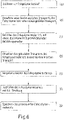
- the inventive method for producing holograms 200 is in 6 schematically sketched: Accordingly, for the production of holograms 200, the photopolymer laminate 300 is first provided, in the roll-to-roll process in the form of a strip-shaped material that is wound up on the feed roll 1110 (method step (A)). This laminate contains the photopolymer material 310 in which a hologram 200 is to be formed.
- the photopolymer material 310 / photopolymer laminate 300 is then transferred to the first buffer device 1200 in order to convert the continuous transport of the material or laminate into clocked transport in the subsequent exposure device 1300 (process step (B)) .
- the photopolymer material 310 / photopolymer laminate 300 is transferred to the exposure device. There the photopolymer material is exposed with an exposure pattern forming the volume hologram 200 (method step (C)).
- the photopolymer material 310/photopolymer laminate 300 is then transferred to the second buffer device 1400, where the clocked transport in the exposure device 1300 is converted back into continuous transport (method step (D)).
- the photopolymer material 310/photopolymer laminate 300 enters the fixing device 1500 and in this first enters the UV radiation device 1510, in which the photopolymer material is prepolymerized (method step (E)).
- the photopolymer material 310 / photopolymer laminate 300 is then conveyed into the NIR irradiation device 1520, where it is cured. There the material or laminate is irradiated with NIR radiation (process step (F)).
- the photopolymer material 310/photopolymer laminate 300 is stored and for this purpose conveyed in a roll-to-roll process to a winding device 1600 with a winding roll 1610, where it is wound up in the form of a roll (method step (G)).
- the process according to the invention comprises at least process steps (C) and (F), preferably also the further process step (E).
- Process steps (B) and (D) are advantageous.
Landscapes
- Engineering & Computer Science (AREA)
- Physics & Mathematics (AREA)
- General Physics & Mathematics (AREA)
- Chemical & Material Sciences (AREA)
- Combustion & Propulsion (AREA)
- Life Sciences & Earth Sciences (AREA)
- Microbiology (AREA)
- Mechanical Engineering (AREA)
- General Engineering & Computer Science (AREA)
- Holo Graphy (AREA)
- Credit Cards Or The Like (AREA)
Description
- Die vorliegende Erfindung betrifft ein Verfahren zum Herstellen eines Volumenhologramms in einem Fotopolymermaterial, ferner eine Vorrichtung zum Herstellen des Volumenhologramms, wobei die Vorrichtung insbesondere dazu ausgebildet ist, das erfindungsgemäße Verfahren zum Herstellen des Volumenhologramms ausführen, sowie ein Verfahren zum Herstellen eines Wert- oder Sicherheitsdokuments, das ein Volumenhologramm aufweist und bei dem das Verfahren zum Herstellen des Volumenhologramms angewendet wird.
- Wert- oder Sicherheitsdokumente dienen dazu, die Identität einer Person, beispielsweise beim Übertritt einer Landesgrenze, oder die Identität oder Sache oder einen Anspruch, beispielsweise auf Zahlung eines Geldbetrages oder auf Herausgabe eines Produktes oder Erbringung einer Dienstleistung, zu verifizieren. Hierzu ist sicherzustellen, dass das Produkt nicht oder nur mit erheblichem Aufwand imitiert, gefälscht oder verfälscht werden kann. Das Dokument enthält daher Sicherheitsmerkmale, deren Nachahmung äußerst schwierig oder sogar praktisch unmöglich ist. Beispielsweise besteht das Dokument, wie Banknoten, aus einem nicht ohne weiteres verfügbaren Material. Zusätzlich oder alternativ können Sicherheitsmerkmale durch spezielle Farben, beispielsweise lumineszierende oder optisch variable Farben, optische Sicherheitselemente, wie Hologramme, Kippbilder, kinegrafische Objekte, Linsen- oder Prismenarrays, ferner Guillochen, Melierfasern, Sicherheitsfäden und andere, gebildet sein. Des Weiteren ist es auch erforderlich, dass die Wert- oder Sicherheitsdokumente einfach herstellbar sind.
- Optische Sicherheitselemente können beispielsweise separat hergestellt und dann als Patches, Sicherheitsfäden, Sicherheitsstreifen oder dergleichen auf eine außenliegende Oberfläche auf dem Wert- oder Sicherheitsdokument oder auf eine innenliegende Oberfläche in dem Wert- oder Sicherheitsdokument aufgeklebt werden. Derartige Sicherheitselemente können optisch variable Elemente sein, sodass damit erzeugte visuell wahrnehmbare Erscheinungen je nach dem Winkel, unter dem das Wert- oder Sicherheitsdokument betrachtet wird, entweder erkennbar sind und/oder unterschiedliche Gestalt annehmen können. Hierzu gehören Oberflächen- und Volumenhologramme. Beispielsweise ergibt sich aus
DE 10 2009 007 552 A1 , dass Wert- oder Sicherheitsdokumente beispielsweise mit einem auf holografischem, insbesondere volumenholografischem, Wege hergestellten Sicherheitsmerkmal versehen sein können. - Volumenhologramme können unter anderem zur Herstellung von dreidimensionalen holografischen Disksystemen eingesetzt werden, die als Speicher und Korrelationsvorrichtungen mit hoher Speicherdichte und Korrelationsrate dienen. Hierzu wird beispielsweise das von DuPont hergestellte Fotopolymer HRF-150 verwendet, das zur Herstellung von Transmissionshologrammen mit hoher Auflösung geeignet ist. Die Hologramme werden mit blaugrünem Licht aufgezeichnet. Zur Herstellung der Hologramme wird ein 38 µm dicker Fotopolymerfilm in Form eines Sandwichs zwischen zwei Mylar®-Folien (Marke von DuPont Teijin Film, US) gebildet und mit einer Vorrichtung zur Erzeugung von Hologrammen belichtet. Nach der Belichtung wird das Hologramm durch Bestrahlen mit UV-Strahlung fixiert. (Kevin ,Curtis und Demetri Psaltis: "Characterization of the DuPont Photopolymer for Three-Dimensional Holographic Storage", Applied Optics, Vol. 33, Nr. 23, Seiten 5396-5399, August 1994).
- In
DE 10 2006 023 159 A1 ist ein Herstellungsverfahren für Dokumente mit Hologramm beschrieben, bei dem in einem ersten Schritt ein Hologramm in eine Fotofolie belichtet und fixiert wird und in einem zweiten Schritt die Fotofolie auf einen Dokumententräger aufgeklebt wird. Zur Fixierung wird die Fotofolie durch Bestrahlen mit UV-Licht und anschließendes Trocknen in einem Trockner fixiert. - In
DE 10 2007 019 837 A1 ist ein Verfahren zur Erzeugung der individuellen holografischen Personalinformation eines Volumenhologramms beschrieben, bei dem ein Fotopolymerfilm verwendet wird, der auf einen holografischen Master laminiert wird und anschließend alle optischen Standardelemente des Masters mit Laserlicht in den Film kopiert werden. Der belichtete Fotopolymerfilm wird in üblicher Weise entwickelt, nämlich mit UV-Licht fixiert und bei höheren Temperaturen, bevorzugter Weise bei 120 °C, gebacken. - Die
US 5,024,909 A offenbart ein Verfahren zum Formen eines Hologramms, wobei das Hologramm durch Infrarotstrahlung erwärmt wird. Der Oberbegriff des Anspruchs 1 bzw. 8 entspricht diesem Dokument. - Die
US 5 774 240 A offenbart, dass eine Hologramm-Aufzeichnungsplatte mit einer Infraroterzeugungseinrichtung bestrahlt wird. - Die
US 6 401 360 B1 offenbart Fotoverarbeitung und insbesondere eine Vorrichtung und ein Verfahren zum Trocknen von fotoempfindlichem Material. - Die
EP 0 962 822 A1 offenbart ebenfalls Fotoverarbeitung und eine Vorrichtung und ein Verfahren zum Trocknen von fotoempfindlichem Material. - Die
EP 0 754 987 A2 offenbart eine Gegenstandsplatte zum Aufzeichnen von Hologrammen durch Belichtung, ein Hologramm-Herstellungsverfahren und einen hologrammaufgezeichneten Artikel. - Das Dokument "Anonymous: "Infrared heat-emission spectra, infrared emitter, infrared lamps, IR emitter infrared oven, infrared drier, carbon infrared, carbon emitter, 17. März 2012 (2012-03-17, XP055665492, gefunden im Internet: URL: https://web.archive.org/web/20120317153834/http://www.heraeus-noblelight.com /en/divisions/infrared/furtherinformation/ir_emission_spectra/ir_emission_spectra_ 1.aspx " offenbart Wellenlängenbereiche von verschiedenen Infrarot-Emittertypen.
- Das Dokument "Germany Heraeus ET AL: "Infrared Emitters for Industrial Processes", 1. September 2015 (2015-09-01 ), XP055662400, Gefunden im Internet: URL:https://www.heraeus.com/media/media/hng/doc_hng/products_and_solutions_ 1 /infrared_emitters_and_systems/IR_products_ENupdate.pdf" offenbart Infrarot-Emitter für industrielle Prozesse.
- Das Dokument "Anonymous: "Technologie 1 MICOR", 1. Januar2021 (2021-01-01), Seiten 1-7, XP055873200, Gefunden im Internet:URL:https://www.micor.de/de/technologie" offenbart das Trocknen mit kurzwelliger Infrarotstrahlung.
- Das Dokument "Anonymous: "Infrared Basics and Technology", 2. Juli 2011 (2011-07-02), Seiten 1-56, XP055873251, Gefunden im Internet: URL:https://web.archive.org/web/20110702064109if_/http://heraeusnoblelight.com/media/webm edia_local/media/pdf/ip/downloads/IR_basics_and_technology.pdf " offenbart Infrarot-Basiswissen und Infrarottechnologie.
- Es hat sich gezeigt, dass eine Fixierung der mit den herkömmlichen Methoden erzeugten Volumenhologramme mittels Wärme aufwändig ist. Denn die Wärmebehandlung erfordert eine relativ lange Prozessierungsdauer. Daher muss die Vorrichtung zur Fixierung groß ausgelegt werden, um einen ausreichenden Durchsatz gewährleisten zu können. Daraus ergeben sich verschiedene Nachteile, beispielsweise eine große Wärmekapazität, die in der Vorrichtung gespeichert ist, damit verbunden eine große Trägheit des Systems bei einer Temperaturanpassung sowie hohe Anlagen- und Betriebskosten. Darüber hinaus hat sich auch gezeigt, dass die Qualität und Optik der erzeugten Materialoberflächen nicht immer den erforderlichen Standards genügen.
- Soweit in der Beschreibung und in den Ansprüchen der vorliegenden Anmeldung der Begriff 'Volumenhologramm' verwendet wird, ist darunter ein Hologramm zu verstehen, bei dem das Volumen des Aufnahmematerials (eines Fotopolymermaterials bzw. -laminats) zur Speicherung des holografischen Bildes genutzt wird. Dies soll allerdings nicht ausschließen, dass die Dicke des Aufnahmematerials in der Größenordnung der Wellenlänge der zum Aufzeichnen verwendeten elektromagnetischen Strahlung liegt, d.h. nur wenig größer oder sogar kleiner ist als die Wellenlänge der Strahlung, wenn auch sich die bevorzugte Anwendung der vorliegenden Erfindung auf solche Aufnahmematerialien bezieht, deren Dicke wesentlich größer ist als die Wellenlänge der Strahlung, beispielsweise mindestens größer als die doppelte Wellenlänge. Die Dicke des Aufnahmematerials ist zu großen Dicken hin durch die gewünschten physikalischen Eigenschaften und die Wirtschaftlichkeit begrenzt. Das Volumenhologramm kann ein Transmissionshologramm oder ein Reflexionshologramm sein.
- Soweit in der Beschreibung und in den Ansprüchen der vorliegenden Anmeldung der Begriff 'Wert- oder Sicherheitsdokument' verwendet wird, ist darunter beispielsweise ein Reisepass, Personalausweis, Führerschein, ein Zugangskontrollausweis oder eine andere ID-Karte, ein Fahrzeugschein, Fahrzeugbrief, Visum, Scheck, Zahlungsmittel, insbesondere eine Banknote, eine Scheck-, Bank-, Kredit- oder Barzahlungskarte, Kundenkarte, Gesundheitskarte, Chipkarte, ein Firmenausweis, Berechtigungsnachweis, Mitgliedsausweis, Geschenk- oder Einkaufsgutschein, Frachtbrief oder ein sonstiger Berechtigungsnachweis, Steuerzeichen, Postwertzeichen, Ticket, Jeton oder ein anderes Dokument zu verstehen. Das Wert- oder Sicherheitsdokument kann beispielsweise auch eine Smartcard sein. Das Wert- oder Sicherheitsdokument kann im ID 1-, ID 2-, ID 3- oder in irgendeinem anderen normierten oder nicht normierten Format vorliegen, beispielsweise in Heftform, wie bei einem passähnlichen Gegenstand, oder beispielsweise in Kartenform. Ein Wert- oder Sicherheitsdokument ist im Allgemeinen ein Laminat aus mehreren Dokumentenlagen, die passergenau unter Wärmeeinwirkung und unter erhöhtem Druck flächig miteinander verbunden sind. Diese Dokumente sollen den normierten Anforderungen genügen, beispielsweise gemäß ISO 10373, ISO/IEC 7810, ISO 14443 in der zum Zeitpunkt der Priorität der vorliegenden Anmeldung gültigen Fassung. Die Dokumentenlagen bestehen beispielsweise aus einem Trägermaterial, das sich für eine Lamination eignet. Das Wert- oder Sicherheitsdokument kann zusätzlich zu dem Volumenhologramm, das mit dem Verfahren gemäß der vorliegenden Erfindung hergestellt wird, weitere Sicherheitsmerkmale aufweisen, die individualisierend, insbesondere personalisierend, oder nicht individualisierend sind. Als derartige Sicherheitsmerkmale kommen Guillochen, Wasserzeichen, Prägedrucke, ein Sicherheitsfaden, Mikroschrift, Kippbilder, Hologramme, optisch variable Pigmente, lumineszierende Farben, Durchlichtpasser, Melierfasern und dergleichen in Betracht. Ferner kann das Dokument auch elektronische Komponenten aufweisen, beispielsweise einen RFID-Schaltkreis mit Antenne und RFID-Mikrochip, elektronische Anzeigeelemente, LEDs, berührungsempfindliche Sensoren und dergleichen. Die elektronischen Komponenten können beispielsweise zwischen zwei opaken Lagen des Dokuments versteckt angeordnet sein.
- Das Wert- oder Sicherheitsdokument kann aus einem oder mehreren Polymeren gebildet sein, die ausgewählt sind aus einer Gruppe, umfassend Polycarbonat (PC), insbesondere Bisphenol A-Polycarbonat, Polyethylenterephthalat (PET), deren Derivate, wie Glykol-modifiziertes PET (PETG), Polyethylennaphthalat (PEN), Polyvinylchlorid (PVC), Polyvinylbutyral (PVB), Polymethylmethacrylat (PMMA), Polyimid (PI), Polyvinylalkohol (PVA), Polystyrol (PS), Polyvinylphenol (PVP), Polypropylen (PP), Polyethylen (PE), thermoplastische Elastomere (TPE), insbesondere thermoplastisches Polyurethan (TPU), Acrylnitril-Butadien-Styrol-Copolymer (ABS) sowie deren Derivate, oder Papier oder Pappe oder Glas oder Metall oder Keramik. Außerdem kann das Dokument auch aus mehreren dieser Materialien hergestellt sein. Bevorzugt besteht es aus PC oder PC/TPU/PC. Die Polymere können entweder gefüllt oder ungefüllt vorliegen. Im letzteren Falle sind sie vorzugsweise transparent oder transluzent. Falls die Polymere gefüllt sind, sind sie opak. Bevorzugt wird das Dokument aus 3 bis 12, vorzugsweise 4 bis 10, Folien hergestellt. Die Folien können ferner Druckschichten tragen.
- Soweit nachfolgend jeweils Begriffe in der Singularform verwendet werden, beispielsweise 'NIR-Bestrahlungsvorrichtung', 'Reflektorvorrichtung', 'UV-Strahlungsvorrichtung' usw., so können darunter jeweils auch die entsprechenden Pluralformen zu verstehen sein, nämlich 'NIR-Bestrahlungsvorrichtungen', 'Reflektorvorrichtungen', 'UV-Strahlungsvorrichtungen', usw., sofern nicht ausdrücklich etwas anderes angegeben ist. Entsprechendes gilt auch im umgekehrten Sinne.
- Gemäß einem ersten Aspekt betrifft die vorliegende Erfindung ein Verfahren zum Herstellen eines Volumenhologramms in einem Fotopolymermaterial / einer Fotopolymerschicht nach Anspruch 1. Das Verfahren umfasst in einem ersten Verfahrensschritt das Belichten des Fotopolymermaterials mit einem das Volumenhologramm bildenden Belichtungsmuster und in einem zweiten Verfahrensschritt das Fixieren des Volumenhologramms durch Einbringen von Wärmeenergie in das belichtete Fotopolymermaterial, sodass das Fotopolymermaterial aushärtet. Zusätzlich kann das Fixieren auch das Bestrahlen mit elektromagnetischer Strahlung, insbesondere mit UV-Strahlung, umfassen. Diese zusätzliche Behandlung kann insbesondere vor der Wärmebehandlung durchgeführt werden. Die UV-Behandlung kann zu einer Vorpolymerisation des belichteten Fotopolymermaterials führen. Ob eine UV-Behandlung erforderlich ist oder nicht, hängt von der Art des eingesetzten Fotopolymermaterials ab. Die anschließende Wärmebehandlung führt zur abschließenden Polymerisation des belichteten Fotopolymermaterials. Weiter wird die Wärmeenergie durch Einstrahlen von elektromagnetischer Strahlung im kurzwelligen Infrarot-Spektralbereich eingebracht. Diese elektromagnetische Strahlung liegt dabei im nahen Infrarot-Bereich, ganz besonders bevorzugt im Wellenlängenbereich von 760 nm bis 2000 nm (2 µm), am meisten bevorzugt im Wellenlängenbereich von 800 nm bis 1200 nm (1,2 µm).
- Gemäß einem zweiten Aspekt betrifft die vorliegende Erfindung ein Verfahren zum Herstellen eines Wert- oder Sicherheitsdokuments nach Anspruch 7. Hierzu umfasst das Verfahren das Herstellen eines Dokumentenrohlings und das Applizieren eines Volumenhologramms auf den Dokumentenrohling. Erfindungsgemäß wird das Volumenhologramm mit dem vorgenannten Herstellverfahren gemäß der vorliegenden Erfindung hergestellt.
- Gemäß einem dritten Aspekt betrifft die vorliegende Erfindung eine Vorrichtung zum Herstellen eines Volumenhologramms in einem Fotopolymermaterial, insbesondere in einer Fotopolymerschicht, nach Anspruch 8. Diese Vorrichtung ist insbesondere zur Durchführung des Verfahrens zum Herstellen eines Volumenhologramms in dem Fotopolymermaterial gemäß der vorliegenden Erfindung ausgebildet. Die Vorrichtung weist eine Belichtungsvorrichtung zum Belichten des Fotopolymermaterials mit einem das Volumenhologramm bildenden Belichtungsmuster und eine Fixiervorrichtung zum Fixieren des Volumenhologramms durch Einbringen von Wärmeenergie in das belichtete Fotopolymermaterial auf. Erfindungsgemäß weist die Fixiervorrichtung eine NIR-Bestrahlungsvorrichtung (NIR: nahes Infrarot) auf, in der das Fotopolymermaterial mit elektromagnetischer Strahlung im kurzwelligen Infrarot-Spektralbereich, d.h. mit elektromagnetischer Strahlung im nahen Infrarot-Bereich, besonders bevorzugt im Wellenlängenbereich von 760 nm bis 2000 nm und am meisten bevorzugt von 800 nm bis 1200 nm, bestrahlt wird. Die Fixiervorrichtung weist mindestens zwei NIR-Strahler auf, die die genannte elektromagnetische Strahlung emittieren. Die Fixiervorrichtung kann zusätzlich auch eine UV-Strahlungsvorrichtung aufweisen. Eine derartige UV-Strahlungsvorrichtung weist mindestens einen UV-Strahler auf, der die UV-Strahlung emittiert, beispielsweise Strahlung im UVA-Spektralbereich (380 nm bis 315 nm). Der UV-Strahlungsvorrichtung kann die NIR-Bestrahlungsvorrichtung in der Durchlaufrichtung des Fotopolymermaterials durch die Herstellvorrichtung nachgelagert sein. Wie vorstehend erläutert, dient die UV-Strahlungsvorrichtung dazu, das belichtete Fotopolymermaterial vorzupolymerisieren. Die anschließende Wärmebehandlung in der NIR-Bestrahlungsvorrichtung führt zur abschließenden Polymerisation des belichteten Fotopolymermaterials.
- Durch die Wärmebehandlung des belichteten Fotopolymermaterials mit elektromagnetischer Strahlung im kurzwelligen Infrarot-Spektralbereich anstelle einer herkömmlichen Behandlung mit Warmluft wird ein sekundenschneller thermischer Prozess zur Fixierung des Hologramms in dem Fotopolymermaterial ermöglicht. Diese signifikante Verkürzung der Prozessierungsdauer gegenüber der herkömmlichen Wärmebehandlung ist auf die Eigenschaften des Fotopolymermaterials zurückzuführen, die elektromagnetische Strahlung in dem genannten Spektralbereich nur wenig und damit im gesamten Volumen des Fotopolymermaterials praktisch gleichmäßig zu absorbieren. Dieses Verhalten gilt auch bei der üblichen Verwendung eines Fotopolymerlaminats, in der das Fotopolymermaterial zwischen anderen Polymerfolien sandwichartig angeordnet ist. Dadurch kann die Strahlung weit in das Material eindringen und wird darin gleichmäßig absorbiert. Folglich wird eine homogene Erwärmung ermöglicht, sodass weiter innen liegende Materialbereiche nicht wie bei herkömmlichen Verfahren allein durch die langsam wirkenden Wärmeleitungsprozesse erhitzt werden, sondern unmittelbar durch Strahlungsabsorption, sodass eine Erwärmung spontan und damit sehr schnell durch Volumenbeheizung eintritt.
- Aus der Erfindung ergeben sich damit viele Vorteile gegenüber einer herkömmlichen Vorgehensweise zum Fixieren des durch Belichtung erzeugten Hologramms, nämlich eine gleichmäßige und schnelle Polymerisation des belichteten Holografiematerials, eine gleichmäßige Qualität und Optik der Materialoberflächen, ein effizientes Ausbacken des Holografiematerials, eine Steigerung der Produktionsleistung durch einen optimierten Trocknungsprozess, eine Energie- und Kostenverringerung bei der Trocknung (beim Fixieren), eine maximale Prozesssicherheit sowie die Möglichkeit, das erfindungsgemäße Konzept in bestehende und neue Vorrichtungen zum Herstellen von Volumenhologrammen problemlos integrieren zu können.
- Für die Erzeugung der elektromagnetischen Strahlung im kurzwelligen Infrarot-Spektralbereich stehen handelsübliche NIR-Bandstrahler zur Verfügung, die elektromagnetische Strahlung beispielsweise mit einem Emissionsmaximum von 1200 nm abstrahlen. Die Strahlung kann mittels elliptischer oder parabolischer Reflektoren diffus oder fokussiert auf das Fotopolymermaterial gerichtet werden. Diese NIR-Strahler können insbesondere stabförmig ausgebildet sein, sodass in Verbindung mit einem parabolischen Reflektor ein gleichmäßig ausgeleuchtetes Strahlungsfeld erzeugt wird, in dem sich das Fotopolymermaterial während der Bestrahlung befindet.
- In einer bevorzugten Weiterbildung der vorliegenden Erfindung wird die elektromagnetische NIR-Strahlung während einer Zeitdauer von 0,5 min bis 10 min, weiter bevorzugt von 0,75 min bis 5 min und am meisten bevorzugt von 1 min bis 2 min, eingestrahlt. Diese Zeitdauer reicht aus, um das Hologramm in dem Fotopolymermaterial zu fixieren. Diese Zeitdauer ist deutlich kürzer als die mit manchen herkömmlichen Trocknungsverfahren benötigte Prozessierungsdauer, beispielsweise die Prozessierungsdauer bei einer Warmlufttrocknung. In letzterem Falle ist es im Allgemeinen erforderlich, das Fotopolymermaterial über eine Zeitdauer von 15 min bis 20 min zu behandeln, um die gewünschte Polymerisation des Materials zu erreichen. Die kurze Fixierungszeit mit dem erfindungsgemäßen Verfahren ermöglicht eine kompakte Bauweise der Fixiervorrichtung und erfordert außerdem einen nur geringen Energieaufwand.
- In einer weiteren bevorzugten Weiterbildung der vorliegenden Erfindung wird das Fotopolymermaterial durch die Einstrahlung der elektromagnetischen NIR-Strahlung auf eine Temperatur von nicht mehr als 160 °C, weiter bevorzugt von nicht mehr als 150 °C und am meisten bevorzugt von nicht mehr als 120 °C, erwärmt. Dadurch wird eine schonende Behandlung des Fotopolymermaterials erreicht. Durch die Volumenbeheizung des Materials wird zudem vermieden, dass sich im Material lokale Temperaturspitzen einstellen.
- In einer weiteren bevorzugten Weiterbildung der vorliegenden Erfindung wird die Temperatur des Fotopolymermaterials während des Einbringens der Wärmeenergie gemessen. Hierzu kann die NIR-Bestrahlungsvorrichtung zusätzlich Temperatursensoren aufweisen. Damit ist es möglich, die Temperatur in dem Fotopolymermaterial innerhalb eines engen Bereiches einzustellen. Hierzu kann die Leistung eines NIR-Strahlers in der NIR-Bestrahlungsvorrichtung in Abhängigkeit von der gemessenen Temperatur in dem Fotopolymermaterial geregelt werden. Dies ermöglicht zum einen, die Temperatur auf einen Mindestwert einzustellen, damit das Hologramm im Fotopolymermaterial so schnell wie möglich fixiert wird, und zum anderen, dass eine maximale Temperatur nicht überschritten wird, womit gewährleistet wird, dass das Fotopolymermaterial thermisch nicht überlastet wird.
- In einer weiteren bevorzugten Weiterbildung der vorliegenden Erfindung wird das Fotopolymermaterial in der Belichtungsvorrichtung mit Laserstrahlung beaufschlagt, um das Volumenhologramm zu erzeugen. Wenn ein mehrfarbiges Volumenhologramm erzeugt werden soll, wird Laserstrahlung mit unterschiedlichen Frequenzen eingesetzt, beispielsweise durch Verwendung von drei Laservorrichtungen, die beispielsweise rote bzw. grüne bzw. blaue Strahlung emittieren.
- In der vorliegenden Erfindung wird das Fotopolymermaterial in einem Rolle-zu-Rolle-Prozess verarbeitet, sodass das Herstellverfahren kontinuierlich durchgeführt werden kann. Hierzu wird das Fotopolymermaterial bandförmig und auf einer Zuführrolle aufgewickelt vorgelegt. Die Zuführrolle bildet eine Versorgungsvorrichtung für die Fixiervorrichtung mit dem bandförmigen Fotopolymermaterial. Für die Prozessierung wird das Material von der Rolle abgewickelt und gelangt zunächst in die Belichtungsvorrichtung, in der das Material mit dem das Volumenhologramm bildenden Belichtungsmuster belichtet wird. Anschließend gelangt das bandförmige Material in die Fixiervorrichtung, die zumindest die NIR-Bestrahlungsvorrichtung aufweist. In der Fixiervorrichtung wird das Fotopolymermaterial mit der elektromagnetischen Strahlung im kurzwelligen Infrarot-Spektralbereich bestrahlt. Gegebenenfalls weist die Fixiervorrichtung auch die UV-Strahlungsvorrichtung auf, mit der das in der Belichtungsvorrichtung belichtete Fotopolymermaterial vorpolymerisiert wird. Die UV-Strahlungsvorrichtung ist in der Durchlaufrichtung des Fotopolymermaterials vorzugsweise vor der NIR-Bestrahlungsvorrichtung angeordnet, sodass das Material zuerst die UV-Strahlungsvorrichtung und erst dann die NIR-Bestrahlungsvorrichtung durchläuft. Nach der Prozessierung des Bandmaterials in der Fixiervorrichtung gelangt es zu einer Aufwickelvorrichtung, in der das Material auf eine Aufwickelrolle aufgewickelt wird.
- In einer besonders bevorzugten Ausführungsform der vorliegenden Erfindung wird das Fotopolymermaterial vor dem Belichten durch eine erste Puffervorrichtung geführt, in der das Fotopolymermaterial abschnittsweise zwischengespeichert wird. Diese erste Puffervorrichtung ist in der Durchlaufrichtung des Fotopolymermaterials durch die Herstellvorrichtung vor der Belichtungsvorrichtung angeordnet. Damit wird bezweckt, dass das Fotopolymermaterial für die Belichtung in der Belichtungsvorrichtung ortsfest fixiert werden kann, um eine präzise Übertragung des das Volumenhologramm bildenden Belichtungsmusters auf das Material zu ermöglichen. Dies erfordert einen intermittierenden (getakteten) Transport des Fotopolymermaterials durch die Belichtungsvorrichtung. Nach dem Belichten eines Abschnittes des Bandmaterials wird das Bandmaterial in der Belichtungsvorrichtung weiterbefördert, damit ein neuer Abschnitt mit einem weiteren Belichtungsmuster belichtet werden kann. Zwischen diesen Beförderungsschritten ist das Fotopolymermaterial in der Belichtungsvorrichtung fixiert und damit immobil. Damit das Bandmaterial von der Versorgungsvorrichtung dennoch kontinuierlich an die Belichtungsvorrichtung weiterbefördert werden kann, puffert die erste Puffervorrichtung die intermittierende Bewegung in der Belichtungsvorrichtung ab. Hierzu wird ein Abschnitt des Bandmaterials während des Zeitabschnittes, in dem das Bandmaterial in der Belichtungsvorrichtung ortsfest gehalten und belichtet wird, in die erste Puffervorrichtung hineinbefördert, ohne zu der Belichtungsvorrichtung weiter transportiert zu werden. Erst wenn die Belichtung abgeschlossen ist und das Bandmaterial in der Belichtungsvorrichtung weiter befördert wird, wird der in die erste Puffervorrichtung hineinbeförderte Bandmaterialabschnitt in die Belichtungsvorrichtung nachgeliefert.
- In einer weiteren besonders bevorzugten Ausführungsform der vorliegenden Erfindung wird das Fotopolymermaterial nach dem Belichten und vor dem Einbringen der Wärmeenergie durch eine zweite Puffervorrichtung geführt, in der das Fotopolymermaterial abschnittsweise zwischengespeichert wird. Die zweite Puffervorrichtung ist in der Durchlaufrichtung des Fotopolymermaterials durch die Herstellvorrichtung hinter der Belichtungsvorrichtung und vor der Fixiervorrichtung angeordnet. Wie im Falle der Beförderung von der Versorgungsvorrichtung zur Belichtungsvorrichtung durch die erste Puffervorrichtung wird die intermittierende Bewegung des Bandmaterials auch bei der weiteren Beförderung von der Belichtungsvorrichtung zur Fixiervorrichtung durch die zweite Puffervorrichtung gepuffert. Auch hierdurch wird ein kontinuierlicher Bandtransport zur Fixiervorrichtung erreicht, während das Bandmaterial in der Belichtungsvorrichtung intermittierend bewegt wird.
- Erfindungsgemäß wird die Wärmeenergie von beiden Seiten in das belichtete Fotopolymermaterial eingestrahlt. Dadurch wird eine sehr homogene Einbringung der Wärmeenergie in das Fotopolymermaterial erreicht. Hierzu sind NIR-Strahler an beiden Seiten des Durchlaufweges für das bandförmige Fotopolymermaterial angeordnet, d.h. an jeder Seite des Fotopolymermaterials jeweils mindestens ein NIR-Strahler.
- Dabei wird die Wärmeenergie mittels eines der beiden die elektromagnetische Strahlung emittierenden NIR-Strahler, der an einer ersten Seite des Fotopolymermaterials angeordnet ist, in das Fotopolymermaterial eingebracht und nach Durchstrahlen des Fotopolymermaterials an einer Reflektorvorrichtung, die an einer zweiten der ersten Seite gegenüberliegenden Seite des Fotopolymermaterials angeordnet ist, reflektiert. An einer zweiten der ersten Seite gegenüberliegenden Seite des Fotopolymermaterials ist also eine Reflektorvorrichtung für die von der NIR-Bestrahlungsvorrichtung emittierte und durch das Fotopolymermaterial hindurchgestrahlte elektromagnetische Strahlung angeordnet, die dem NIR-Strahler gegenüberliegend angeordnet ist.
- Da das Fotopolymermaterial bandförmig ausgebildet ist und in einem Rolle-zu-Rolle-Prozess prozessiert wird, befinden sich in der NIR-Strahlungsvorrichtung erfindungsgemäß mindestens zwei NIR-Strahler, die entlang eines Durchlaufweges durch die Herstellvorrichtung hintereinander angeordnet sind.
- Weiter erfindungsgemäß liegen die mindestens zwei NIR-Strahler in der NIR-Strahlungsvorrichtung an einer Seite des Durchlaufweges jeweils einer Reflektorvorrichtung an der jeweils anderen Seite des Durchlaufweges gegenüber, wobei die NIR-Strahler und die Reflektorvorrichtungen an den jeweiligen Seiten alternierend, d.h. in der Durchlaufrichtung hintereinander abwechselnd, angeordnet sind.
- Das Fotopolymermaterial kann in üblicher Art und Weise verwendet werden. Insbesondere kann das Fotopolymermaterial durch eine Fotopolymerschicht gebildet sein, in der das Hologramm erzeugt wird und die sich zwischen einer Trägerfolie und einer Schutzfolie befindet. Die Fotopolymerschicht bildet zusammen mit diesen Folien ein Fotopolymerlaminat, das in der Herstellvorrichtung prozessiert wird. Die Fotopolymerschicht kann beispielsweise eine Dicke von 10 µm haben, während die Trägerfolie eine Dicke von 50 µm und die Schutzfolie eine Dicke von 21 µm haben können. Grundsätzlich sind für diese Schichten und Folien auch andere Dicken denkbar. Die Trägerfolie und die Schutzfolie können aus PET hergestellt sein. Das Fotopolymerlaminat liegt in Form eines bandförmiger Materials vor (Bandmaterial), das auf einer Zuführrolle aufgewickelt vorgelegt, für die Prozessierung (Bildung des Volumenhologramms) von der Zuführrolle abgewickelt und prozessiert und nach der Prozessierung wieder auf eine Aufwickelrolle aufgewickelt wird.
- Zum Applizieren des Hologramms auf einen Dokumentenrohling wird ein dem Hologramm entsprechender Abschnitt von dem Fotopolymermaterial von dem Bandmaterial vereinzelt, beispielsweise abgeschnitten. Vor dem Applizieren des Hologramms auf den Rohling wird die Trägerfolie von dem Fotopolymermaterial abgezogen. Vorzugsweise wird auch die Schutzfolie von dem Fotopolymermaterial abgezogen und zwar nach dem Aufbringen des Laminats aus Fotopolymermaterial/-schicht und Schutzfolie auf den Rohling. Zum Applizieren des Hologramms auf den Rohling wird vorzugsweise ein Kleber verwendet. Das belichtete und fixierte Fotopolymermaterial kann das Wert- oder Sicherheitsdokument ganzflächig bedecken oder nur teilweise. Das Hologramm kann einen Teil der von dem Fotopolymermaterial eingenommenen Fläche einnehmen. Zum Schutz gegen Beschädigungen und Manipulation befindet sich in dem fertigen Dokument vorzugsweise eine transparente Schutzschicht über dem aufgebrachten Material, die durch eine Lackschicht gebildet werden kann.
- Das Hologramm kann individualisierend sein, d.h. dass das Hologramm einem bestimmten Subjekt (Person, Tier, Gegenstand) zuordenbar ist oder eine Kennzeichnung bildet, die das Dokument selbst oder eine Gruppe von Dokumenten eindeutig bezeichnet, oder es ist personalisierend, d.h. dass das Hologramm einer Person zuordenbar ist. Oder das Hologramm ist nicht individualisierend und dient lediglich der Verifikation des Dokuments. Demgemäß kann das Hologramm beispielsweise das Passbild der Person, der das Dokument zugeordnet ist, eine Seriennummer oder ein Wappen zeigen.
- Zur Herstellung des Wert- oder Sicherheitsdokuments mit dem erfindungsgemäß hergestellten Volumenhologramm wird zunächst ein Dokumentenrohling hergestellt. Auf diesen wird das fertig gestellte Hologramm aufgebracht, beispielsweise aufgeklebt. Der Dokumentenrohling kann in üblicher Weise beispielsweise durch Laminieren von Polymerfolien hergestellt werden und, abgesehen von dem Volumenhologramm, bereits alle oder fast alle übrigen Sicherheitsmerkmale des fertigen Wert- oder Sicherheitsdokuments enthalten. Nach dem Aufbringen des Fotopolymermaterials mit dem darin enthaltenen Hologramm kann schließlich noch eine Schutzschicht aufgebracht werden, die das Hologramm gegen Beschädigungen und Manipulation schützt.
- Die vorliegende Erfindung wird nachfolgend anhand von Figuren näher erläutert, wobei die dargestellten Zeichnungen und Beispiele lediglich exemplarischen Charakter haben und keine Einschränkung hinsichtlich der Tragweite der beschriebenen Erfindung darstellen. Es zeigen im Einzelnen:
- Fig. 1
- ein Wert- oder Sicherheitsdokument mit einem Hologramm in einer schematischen isometrischen Darstellung;
- Fig. 2
- das Wert- oder Sicherheitsdokument von
Fig. 1 in einer schematischen Schnittdarstellung; - Fig. 3
- ein Fotopolymerlaminat zur Herstellung von Hologrammen in einer schematischen Schnittdarstellung;
- Fig. 4
- eine Darstellung einer erfindungsgemäßen Vorrichtung zum Herstellen eines Volumenhologramms in einem Fotopolymermaterial in einer schematischen Seitenansicht;
- Fig. 5
- die spektrale Abhängigkeit der Emission eines NIR-Strahlers;
- Fig. 6
- eine schematische Darstellung der Schritte des beanspruchten Verfahrens zum Herstellen eines Volumenhologramms in einem Fotopolymermaterial.
- In den Figuren bezeichnen gleiche Bezugszeichen gleiche Elemente und/oder Elemente mit derselben Funktion. Die Figuren zeigen die Gegenstände nicht in jedem Falle maßstäblich zueinander. Ferner sind auch die Größenverhältnisse einzelner Elemente zu denen anderer in einer Figur oder zwischen den Figuren nicht in jedem Falle maßstäblich zueinander dargestellt.
- Ein Wert- oder Sicherheitsdokument 100 in Form einer Ausweiskarte ist in
Fig. 1 dargestellt. Diese Karte weist vorzugsweise die normierten Maße im Format ID 1 gemäß DIN/IEC 7810 in der zum Zeitpunkt der Priorität der vorliegenden Anmeldung gültigen Fassung auf. Die Karte kann in Form eines Laminats auf der Basis von PC und PET hergestellt sein, die teilweise opak (innere Lagen) und teilweise transparent (äußere Lagen) sind. Durch innere opake Lagen kann eine sich innen befindende elektronische Schaltung nach außen hin gegen Sicht abgeschirmt sein. Die Karte hat eine Vorderseite 101 und eine Rückseite 102 (inFig. 1 nicht dargestellt). Auf der Vorderseite sind ein Gesichtsbild des Inhabers in Form eines Passphotos 110 sowie Datenfelder 120, 130, die Daten des Inhabers sowie weitere Daten wiedergeben, wie eine Seriennummer und dergleichen, sichtbar. Außerdem befindet sich auf der Vorderseite ein Hologramm 200, das in einem Fotopolymermaterial gebildet ist (inFig. 1 nicht dargestellt). - In
Fig. 2 ist die Karte 100 vonFig. 1 in einer schematischen Schnittdarstellung gezeigt, wobei auf die Darstellung von Einzelheiten des Kartenmaterials unterhalb des belichteten und fixierten Fotopolymermaterials 310 verzichtet wurde, beispielsweise eine sich im Karteninneren befindende elektronische Schaltung, wie eine RFID-Schaltung mit RFID-Chip und RFID-Antenne, und verschiedene Lagenstrukturen. Auf die Oberseite des Kartenrohlings 150 ist Fotopolymermaterial 310, das den Rohling beispielsweise ganzflächig bedeckt, aufgebracht/aufgeklebt. Da die Trägerfolie 320 und die Schutzfolie 330 des Fotopolymerlaminats 300 abgezogen sind, verbleibt auf der Karte allein die belichtete und fixierte Fotopolymerschicht (Fotopolymermaterial). In dieses Material ist ein Volumenhologramm 200 mit dem erfindungsgemäßen Verfahren einbelichtet und darin fixiert (Fig. 1 ). Zum Schutz gegen Beschädigungen und Manipulation ist zusätzlich auf die Fotopolymerschicht eine Schutzschicht 160 aufgebracht, die beispielsweise aus einem transparenten, farblosen Schutzlack gebildet sein kann. - In
Fig. 3 ist ein Fotopolymerlaminat 300 in einer schematischen Schnittansicht gezeigt. Dieses Laminat ist leicht handhabbar, während das Fotopolymermaterial 310 äußerst empfindlich ist. Die Fotopolymerschicht 310 ist in dem Laminat sandwichartig zwischen einer unteren Trägerfolie 320 und einer oberen Schutzfolie 330 angeordnet. Die Trägerfolie und die Schutzfolie sind beispielsweise aus PET gebildet. Die Dicke der Trägerfolie beträgt beispielsweise 50 µm, die der Schutzfolie 21 µm und die der Fotopolymerschicht beispielsweise 10 µm. - In
Fig. 4 ist eine erfindungsgemäße Vorrichtung 1000 zum Herstellen eines Volumenhologramms 200 in einem Fotopolymermaterial 310, das in Form von Fotopolymerlaminat 300 bereitgestellt wird, schematisch dargestellt. Es handelt sich um eine Vorrichtung, in der ein Rolle-zu-Rolle-Prozess durchgeführt wird. Hierzu ist eine Versorgungsvorrichtung 1100 mit einer Zuführrolle 1110 mit noch nicht prozessiertem Fotopolymermaterial vorgesehen. Auf der Zuführrolle ist das Fotopolymerlaminat aufgewickelt und kann durch Abwickeln bereitgestellt werden. - Der Versorgungsvorrichtung 1100 in der Durchlaufrichtung R des Fotopolymerlaminats 300 in der Herstellvorrichtung 1000 nachgelagert ist eine erste Puffervorrichtung 1200. Diese Vorrichtung kann wie dargestellt drei Umlenkrollen 1210, 1220, 1230 enthalten, die das Fotopolymerlaminat auf einem gewundenen Durchlaufweg D durch diese Vorrichtung führen. Von diesen Umlenkrollen sind die beiden oberen Umlenkrollen 1210, 1220 ortsfest in der Vorrichtung angeordnet, während die mittige untere Umlenkrolle 1230 vertikal verschiebbar ist, sodass sich die Länge des in der Vorrichtung befindlichen Abschnittes des Fotopolymerlaminats verändern kann.
- Der ersten Puffervorrichtung 1200 in der Durchlaufrichtung R des Fotopolymerlaminats 300 in der Herstellvorrichtung 1000 nachgelagert ist eine Belichtungsvorrichtung 1300, mit der das durch diese hindurchlaufende Fotopolymerlaminat mit dem das Volumenhologramm 200 bildenden Belichtungsmuster belichtet wird. Hierzu sind vorliegend drei Laservorrichtungen 1310, 1320, 1330 gezeigt, deren Laserstrahlen über Umlenkspiegel 1340, 1350, 1360 auf das Fotopolymerlaminat bzw. das darin befindliche Fotopolymermaterial 310 gerichtet werden. Diese drei Laser emittieren Laserlicht mit unterschiedlichen Wellenlängen, sodass ein mehrfarbiges Hologramm erzeugt werden kann. Beispielsweise emittiert die erste Laservorrichtung 1310 rote, die zweite Laservorrichtung 1320 grüne und die dritte Laservorrichtung 1330 blaue Laserstrahlung. Die Laserstrahlen werden mit geeigneten optischen Mitteln (nicht dargestellt) auf das Fotopolymermaterial fokussiert, sodass auch sehr kleine Belichtungsstrukturen erzeugt werden können. Die hierfür erforderlichen optischen Elemente sind nicht dargestellt.
- Der Belichtungsvorrichtung 1300 in der Durchlaufrichtung R des Fotopolymerlaminats 300 in der Herstellvorrichtung 1000 nachgelagert ist eine zweite Puffervorrichtung 1400. Wie die erste Puffervorrichtung 1200 kann auch diese wie dargestellt drei Umlenkrollen 1410, 1420, 1430 enthalten, die das Fotopolymerlaminat auf einem gewundenen Durchlaufweg D durch die Vorrichtung führen. Von diesen Umlenkrollen sind die beiden oberen Umlenkrollen 1410, 1420 ortsfest in der Vorrichtung angeordnet, während die mittige untere Umlenkrolle 1430 vertikal verschiebbar ist, sodass sich die Länge des in der Vorrichtung befindlichen Abschnittes des Fotopolymerlaminats verändern kann.
- Der zweiten Puffervorrichtung 1400 in der Durchlaufrichtung R des Fotopolymerlaminats 300 in der Herstellvorrichtung 1000 nachgelagert ist die Fixiervorrichtung 1500. Diese weist eine UV-Strahlungsvorrichtung 1510 und eine NIR-Bestrahlungsvorrichtung 1520 auf. Der UV-Strahlungsvorrichtung 1510 ist die NIR-Bestrahlungsvorrichtung 1520 in der Durchlaufrichtung R des Fotopolymerlaminats durch die Herstellvorrichtung nachgelagert.
- In der UV-Strahlungsvorrichtung ist ein UV-Strahler 1511 angeordnet, der beispielsweise UV-Strahlung im UVA-Spektralbereich aussendet. Der UV-Strahler kann beispielsweise eine Gasentladungslampe sein, wie eine Osram L18/965-Gasentladungslampe. Diese Strahlung trifft auf das durch diese Vorrichtung hindurchgeführte Fotopolymerlaminat 300. Dadurch wird das Fotopolymermaterial 310 entsprechend dem durch die Belichtung generierten Volumenhologramm 200 vorpolymerisiert.
- In der NIR-Bestrahlungsvorrichtung 1520 sind zwei NIR-Strahler angeordnet und zwar ein erster NIR-Strahler 1521 oberhalb des Durchlaufweges D für das Fotopolymerlaminat 300 und ein zweiter NIR-Strahler 1522 unterhalb des Durchlaufweges. Diese Strahler erzeugen NIR-Strahlung innerhalb eines Wellenlängenbereiches von beispielsweise 800 nm bis 2000 nm. Die NIR-Strahler können handelsübliche Vorrichtungen sein, beispielsweise Strahler vom TYP MICOR-*KIR (Micor GmbH, DE), die ein Emissionsmaximum der Wellenlänge bei 1,2 µm haben. Diese Strahler können beispielsweise parabolförmige Reflektorausführungen aufweisen, sodass ein gleichmäßig ausgeleuchtetes Strahlungsfeld erzeugt wird.
- Den beiden NIR-Strahlern 1521, 1522 sind Reflektorvorrichtungen 1523, 1524 auf der jeweils anderen Seite des Durchlaufweges D gegenüberliegend angeordnet. Die von den NIR-Strahlern an jeweils einer Seite des Fotopolymerlaminats 300 erzeugte NIR-Strahlung tritt durch das Laminatmaterial hindurch, trifft auf dessen anderer Seite auf die Reflektorvorrichtungen und wird von diesen wieder zurückgeworfen. Dadurch gelangt es erneut in den Bereich des Fotopolymermaterials 310. Das Material wird auf diese Weise auch in dessen Volumen noch gleichmäßiger mit Infrarot-Strahlung beaufschlagt als ohne die Reflektorvorrichtungen. Dadurch dass die NIR-Strahler zudem an unterschiedlichen Seiten des Durchlaufweges angeordnet sind, wird das Fotopolymermaterial beim Durchlaufen der NIR-Bestrahlungsvorrichtung 1520 nochmals weiter vergleichmäßigt mit NIR-Strahlung in dessen Volumen beaufschlagt.
- Zur schonenden und dennoch schnellen Prozessierung des Fotopolymerlaminats 300 in der NIR-Bestrahlungsvorrichtung 1520 dienen Temperatursensoren 1525, 1526, die an den NIR-Strahlern 1521, 1522 und diesen in der Durchlaufrichtung R nachgelagert angeordnet sind. Mit diesen Sensoren wird die Temperatur des Fotopolymerlaminats 300 bzw. des Fotopolymermaterials 310 ermittelt. Durch eine Steuerung/Regelung (nicht dargestellt) kann die Leistung der NIR-Strahler gesteuert werden, sodass die Temperatur des Laminats/Materials weitgehend innerhalb eines vorgegebenen Temperaturbereiches konstant gehalten wird. Dadurch wird eine schonende und dennoch schnelle Aushärtung des Materials erreicht.
- Der Fixiervorrichtung 1500 in der Durchlaufrichtung R des Fotopolymerlaminats 300 in der Herstellvorrichtung 1000 nachgelagert ist eine Aufwickelvorrichtung 1600 mit einer Aufwickelrolle 1610. Das Laminat wird auf der Aufwickelrolle zu einer Rolle aufgewickelt.
- Die fertig gestellte Rolle des Fotopolymerlaminats 300 enthält eine Vielzahl von Hologrammen 200, die in dem Fotopolymermaterial 310 gebildet sind. Zur weiteren Verarbeitung werden die einzelnen Abschnitte mit jeweils einem Hologramm 200 auf einen zugehörigen Dokumentenrohling 150 aufgeklebt. Hierzu werden zunächst die Trägerfolie 320 und nach dem Aufbringen des Laminats aus Fotopolymermaterial und Schutzfolie 330 auf den Rohling auch die Schutzfolie abgezogen, sodass sich schließlich allein das Fotopolymermaterial 310 auf dem Dokumentenrohling befindet.
- In
Fig. 5 ist die Leistung P [Watt] der von den NIR-Strahlern 1521, 1522 emittierten NIR-Strahlung in Abhängigkeit von der Wellenlänge λ [µm] beispielhaft aufgezeichnet. Je nach Wellenlänge, bei der ein Leistungsmaximum auftritt, ist die Leistung in diesem Maximum unterschiedlich hoch. Je energiereicher die Strahlung ist, d.h. je kürzer die Wellenlänge ist, desto kleiner ist der Wellenlängenbereich, auf den sich die Gesamtleistung verteilt. Wegen einer relativ schmalen Emissionsbande bei kurzerwelliger Strahlung ist die Leistung im Fall (A) größer als im Fall (B), bei dem das Emissionsmaximum bei größerer Wellenlänge liegt. Am niedrigsten ist das Leistungsmaximum im Fall (C), bei dem dieses bei der größten Wellenlänge der betrachteten Fälle liegt. - Das erfindungsgemäße Verfahren zum Herstellen von Hologrammen 200 ist in
Fig. 6 schematisch skizziert:
Zur Herstellung von Hologrammen 200 wird demgemäß zunächst das Fotopolymerlaminat 300 bereitgestellt, im Rolle-zu-Rolle-Prozess in Form eines bandförmigen Materials, das auf der Zuführrolle 1110 aufgewickelt vorliegt (Verfahrensschritt (A)). Dieses Laminat enthält das Fotopolymermaterial 310, in dem ein Hologramm 200 gebildet werden soll. - Im Rolle-zu-Rolle-Prozess wird das Fotopolymermaterial 310 / Fotopolymerlaminat 300 anschließend in die erste Puffervorrichtung 1200 überführt, um den kontinuierlichen Transport des Materials bzw. Laminats beim Zuführen in einen getakteten Transport in der nachfolgenden Belichtungsvorrichtung 1300 umzusetzen (Verfahrensschritt (B)).
- Danach wird das Fotopolymermaterial 310 / Fotopolymerlaminat 300 in die Belichtungsvorrichtung überführt. Dort wird das Fotopolymermaterial mit einem das Volumenhologramm 200 bildenden Belichtungsmuster belichtet (Verfahrensschritt (C)).
- Im Rolle-zu-Rolle-Prozess wird das Fotopolymermaterial 310 / Fotopolymerlaminat 300 anschließend in die zweite Puffervorrichtung 1400 überführt, wo der getaktete Transport in der Belichtungsvorrichtung 1300 wieder in einen kontinuierlichen Transport umgesetzt wird (Verfahrensschritt (D)).
- Danach gelangt das Fotopolymermaterial 310 / Fotopolymerlaminat 300 in die Fixiervorrichtung 1500 und in dieser zunächst in die UV-Strahlungsvorrichtung 1510, in der das Fotopolymermaterial vorpolymerisiert wird (Verfahrensschritt (E)).
- Anschließend wird das Fotopolymermaterial 310 / Fotopolymerlaminat 300 in die NIR-Bestrahlungsvorrichtung 1520 befördert, wo es ausgehärtet wird. Dort wird das Material bzw. Laminat mit NIR-Strahlung bestrahlt (Verfahrensschritt (F)).
- Schließlich wird das Fotopolymermaterial 310 / Fotopolymerlaminat 300 gespeichert und hierzu im Rolle-zu-Rolle-Prozess zu einer Aufwickelvorrichtung 1600 mit einer Aufwickelrolle 1610 befördert, wo es rollenförmig aufgewickelt wird (Verfahrensschritt (G)).
- Das erfindungsgemäße Verfahren umfasst zumindest die Verfahrensschritte (C) und (F), vorzugsweise zusätzlich auch den weiteren Verfahrensschritt (E). Die Verfahrensschritte (B) und (D) sind vorteilhaft.
-
- 100
- Wert- oder Sicherheitsdokument, (Ausweis-)Karte
- 101
- Vorderseite
- 102
- Rückseite
- 110
- Passphoto
- 120
- Datenfeld
- 130
- Datenfeld
- 150
- Kartenrohling
- 160
- Schutzschicht
- 200
- (Volumen-)Hologramm
- 300
- Fotopolymerlaminat
- 310
- Fotopolymermaterial, Fotopolymerschicht
- 320
- Trägerfolie
- 330
- Schutzfolie
- 1000
- Vorrichtung zum Herstellen eines Volumenhologramms
- 1100
- Versorgungsvorrichtung
- 1110
- Zuführrolle
- 1200
- erste Puffervorrichtung
- 1210
- ortsfeste Umlenkrolle
- 1220
- ortsfeste Umlenkrolle
- 1230
- vertikal verschiebbare Umlenkrolle
- 1300
- Belichtungsvorrichtung
- 1310
- Laservorrichtung für rote Laserstrahlung
- 1320
- Laservorrichtung für grüne Laserstrahlung
- 1330
- Laservorrichtung für blaue Laserstrahlung
- 1340
- Umlenkspiegel für rote Laserstrahlung
- 1350
- Umlenkspiegel für grüne Laserstrahlung
- 1360
- Umlenkspiegel für blaue Laserstrahlung
- 1400
- zweite Puffervorrichtung
- 1410
- ortsfeste Umlenkrolle
- 1420
- ortsfeste Umlenkrolle
- 1430
- vertikal verschiebbare Umlenkrolle
- 1500
- Fixiervorrichtung
- 1510
- UV-Strahlungsvorrichtung
- 1511
- UV-Strahler
- 1520
- NIR-Bestrahlungsvorrichtung
- 1521
- erster NIR-Strahler
- 1522
- zweiter NIR-Strahler
- 1523
- erste Reflektorvorrichtung
- 1524
- zweite Reflektorvorrichtung
- 1525
- erster Temperatursensor
- 1526
- zweiter Temperatursensor
- 1600
- Aufwickelvorrichtung
- 1610
- Aufwickelrolle
- D
- Durchlaufweg
- NIR
- nahes Infrarot
- R
- Durchlaufrichtung
- UV
- Ultraviolett
Claims (10)
- Verfahren zum Herstellen eines Volumenhologramms (200) in einem Fotopolymermaterial (310), wobei das Verfahren das Belichten des Fotopolymermaterials (310) mit einem das Volumenhologramm (200) bildenden Belichtungsmuster und das Fixieren des Volumenhologramms (200) durch Einbringen von Wärmeenergie in das belichtete Fotopolymermaterial (310) umfasst,wobei die Wärmeenergie durch Einstrahlen von elektromagnetischer Strahlung im kurzwelligen Infrarot-Spektralbereich (NIR) eingebracht wird,dadurch gekennzeichnet, dassdas Fotopolymermaterial (310) in einem Rolle-zu-Rolle-Prozess verarbeitet wird, wobei die Wärmeenergie von beiden Seiten in das belichtete Fotopolymermaterial (310) eingestrahlt wird, wobei mindestens zwei NIR-Strahler (1521, 1522) entlang eines Durchlaufweges (D) des Fotopolymermaterials (310) hintereinander angeordnet sind, wobei die mindestens zwei NIR-Strahler (1521, 1522) an einer Seite des Durchlaufweges (D) jeweils einer Reflektorvorrichtung (1523, 1524) an der jeweils anderen Seite des Durchlaufweges (D) gegenüberliegen, wobei die NIR-Strahler (1521, 1522) und die Reflektorvorrichtungen (1523, 1524) an den jeweiligen Seiten alternierend angeordnet sind.
- Verfahren nach Anspruch 1, dadurch gekennzeichnet, dass die elektromagnetische Strahlung (NIR) während einer Zeitdauer von 1 bis 2 min eingestrahlt wird.
- Verfahren nach einem der vorstehenden Ansprüche, dadurch gekennzeichnet, dass das Fotopolymermaterial (310) durch die Einstrahlung der elektromagnetischen Strahlung (NIR) auf eine Temperatur von nicht mehr als 160 °C erwärmt wird.
- Verfahren nach einem der vorstehenden Ansprüche, dadurch gekennzeichnet, dass während des Einbringens der Wärmeenergie eine Temperatur des Fotopolymermaterials (310) ermittelt wird.
- Verfahren nach einem der vorstehenden Ansprüche, dadurch gekennzeichnet, dass das Fotopolymermaterial (310) vor dem Belichten durch eine erste Puffervorrichtung (1200) geführt wird, in der das Fotopolymermaterial (310) abschnittsweise zwischengespeichert wird.
- Verfahren nach Anspruch 5, dadurch gekennzeichnet, dass das Fotopolymermaterial (310) nach dem Belichten und vor dem Einbringen der Wärmeenergie durch eine zweite Puffervorrichtung (1400) geführt wird, in der das belichtete Fotopolymermaterial (310) abschnittsweise zwischengespeichert wird.
- Verfahren zum Herstellen eines Wert- oder Sicherheitsdokuments (100), umfassend das Herstellen eines Dokumentenrohlings (150) und das Applizieren eines Volumenhologramms (200) auf den Dokumentenrohling (150), wobei das Volumenhologramm (200) mit dem Verfahren nach einem der Ansprüche 1 bis 6 hergestellt wird.
- Vorrichtung (1000) zum Herstellen eines Volumenhologramms (200) in einem Fotopolymermaterial (310), insbesondere zur Durchführung des Verfahrens nach einem der Ansprüche 1 bis 6, wobei die Vorrichtung (1000) eine Belichtungsvorrichtung (1300) zum Belichten des Fotopolymermaterials (310) mit einem das Volumenhologramm (200) bildenden Belichtungsmuster und eine Fixiervorrichtung (1500) zum Fixieren des Volumenhologramms (200) durch Einbringen von Wärmeenergie in das belichtete Fotopolymermaterial (310) aufweist,wobei die Fixiervorrichtung (1500) eine NIR-Bestrahlungsvorrichtung (1520) aufweist, in der das Fotopolymermaterial (310) mit elektromagnetischer Strahlung im kurzwelligen Infrarot-Spektralbereich (NIR) bestrahlt wirddadurch gekennzeichnet, dassdas Fotopolymermaterial (310) in einem Rolle-zu-Rolle-Prozess verarbeitet wird, wobei die Wärmeenergie von beiden Seiten in das belichtete Fotopolymermaterial (310) eingestrahlt wird, wobei mindestens zwei NIR-Strahler (1521, 1522) entlang eines Durchlaufweges (D) des Fotopolymermaterials (310) hintereinander angeordnet sind, wobei die mindestens zwei NIR-Strahler (1521, 1522) an einer Seite des Durchlaufweges (D) jeweils einer Reflektorvorrichtung (1523, 1524) an der jeweils anderen Seite des Durchlaufweges (D) gegenüberliegen, wobei die NIR-Strahler (1521, 1522) und die Reflektorvorrichtungen (1523, 1524) an den jeweiligen Seiten alternierend angeordnet sind.
- Vorrichtung (1000) nach Anspruch 8, dadurch gekennzeichnet, dass die Vorrichtung (1000) ferner eine erste Puffervorrichtung (1200) aufweist, die in einer Durchlaufrichtung (R) des Fotopolymermaterials (310) durch die Herstellvorrichtung (1000) vor der Belichtungsvorrichtung (1300) angeordnet ist.
- Vorrichtung (1000) nach Anspruch 9, dadurch gekennzeichnet, dass die Vorrichtung (1000) ferner eine zweite Puffervorrichtung (1400) aufweist, die in einer Durchlaufrichtung (R) des Fotopolymermaterials (310) durch die Herstellvorrichtung (1000) hinter der Belichtungsvorrichtung (1300) und vor der Fixiervorrichtung (1500) angeordnet ist.
Applications Claiming Priority (2)
| Application Number | Priority Date | Filing Date | Title |
|---|---|---|---|
| DE102015206852.8A DE102015206852A1 (de) | 2015-04-16 | 2015-04-16 | Verfahren und Vorrichtung zum Herstellen eines Volumenhologramms in einem Fotopolymermaterial sowie Verfahren zum Herstellen eines Wert- oder Sicherheitsdokuments |
| PCT/EP2016/058314 WO2016166266A1 (de) | 2015-04-16 | 2016-04-15 | Verfahren und vorrichtung zum herstellen eines volumenhologramms in einem fotopolymermaterial sowie verfahren zum herstellen eines wert- oder sicherheitsdokuments |
Publications (2)
| Publication Number | Publication Date |
|---|---|
| EP3283925A1 EP3283925A1 (de) | 2018-02-21 |
| EP3283925B1 true EP3283925B1 (de) | 2023-01-04 |
Family
ID=55802356
Family Applications (1)
| Application Number | Title | Priority Date | Filing Date |
|---|---|---|---|
| EP16717608.0A Active EP3283925B1 (de) | 2015-04-16 | 2016-04-15 | Verfahren und vorrichtung zum herstellen eines volumenhologramms in einem fotopolymermaterial sowie verfahren zum herstellen eines wert- oder sicherheitsdokuments |
Country Status (3)
| Country | Link |
|---|---|
| EP (1) | EP3283925B1 (de) |
| DE (1) | DE102015206852A1 (de) |
| WO (1) | WO2016166266A1 (de) |
Citations (6)
| Publication number | Priority date | Publication date | Assignee | Title |
|---|---|---|---|---|
| US4485565A (en) * | 1981-06-24 | 1984-12-04 | Afga-Gevaert Aktiengesellschaft | Drying arrangement for photosensitive articles |
| US4778093A (en) * | 1987-04-13 | 1988-10-18 | Walter Renold | Film transport assembly |
| JPH07319144A (ja) * | 1994-05-19 | 1995-12-08 | Konica Corp | 写真感光材料の乾燥装置 |
| JP2001142186A (ja) * | 1999-11-10 | 2001-05-25 | Fuji Photo Film Co Ltd | ハロゲン化銀カラー写真感光材料の現像処理方法 |
| WO2005078533A1 (en) * | 2004-02-10 | 2005-08-25 | Zebra Imaging, Inc. | Deposition of photosensitive media for digital hologram recording |
| US20130119182A1 (en) * | 2011-11-15 | 2013-05-16 | Nittoku Engineering Co., Ltd. | Film intermittent carrying device and film intermittent carrying method |
Family Cites Families (13)
| Publication number | Priority date | Publication date | Assignee | Title |
|---|---|---|---|---|
| US5024909A (en) * | 1988-01-15 | 1991-06-18 | E. I. Du Pont De Nemours And Company | Dry film process for altering wavelength response of holograms |
| DE4130550A1 (de) * | 1991-09-13 | 1993-03-18 | Inst Neue Mat Gemein Gmbh | Optische elemente und verfahren zu deren herstellung |
| US5774240A (en) * | 1992-02-20 | 1998-06-30 | Nikon Corporation | Exposure apparatus for reproducing a mask pattern onto a photo-sensitive surface of a substrate using holographic techniques |
| EP2290472A1 (de) * | 1995-07-18 | 2011-03-02 | Dai Nippon Printing Co., Ltd. | Hologrammaufgezeichneter Artikel |
| DE19809502B4 (de) * | 1997-08-04 | 2007-06-14 | Bundesdruckerei Gmbh | Vorrichtung zur Herstellung einer Kontaktkopie eines Hologramms |
| US6092303A (en) * | 1998-06-05 | 2000-07-25 | Eastman Kodak Company | Apparatus and method for drying photosensitive material using radiant section and an air flow section |
| DE19960920A1 (de) * | 1999-12-17 | 2001-06-28 | Dupont Performance Coatings | Verfahren zur Kennzeichnung temperaturempfindlicher Substrate mit Temperaturüberschreitungen anzeigenden Indikatoren |
| US6401360B1 (en) * | 2000-04-13 | 2002-06-11 | Eastman Kodak Company | Apparatus and method for drying photosensitive material using a radiant heat assembly |
| EP1723475A4 (de) * | 2003-12-12 | 2009-03-25 | Dce Aprilis Inc | Verfahren und vorrichtungen zur fixierung holographischer medien in holographischen datenspeichersystemen |
| DE102006023159A1 (de) | 2006-05-16 | 2007-11-22 | Hologram Industries Research Gmbh | Herstellungsverfahren für Dokumente mit Hologramm sowie Hologramm |
| DE102007019837A1 (de) | 2007-04-25 | 2008-11-13 | Hologram Industries Research Gmbh | Volumenhologramm, Master zur Herstellung der Standardelemente des Volumenhologramms und Verfahren zur nachträglichen Hologrammindividualisierung bei der Applikation auf Personal- und Wertdokumente |
| DE102008052067A1 (de) * | 2008-10-17 | 2010-04-22 | Ovd Kinegram Ag | Volumenhologramm mit Expansionsmittelschicht bzw. Kontraktionsmittelschicht |
| DE102009007552A1 (de) | 2009-02-04 | 2010-08-05 | Bundesdruckerei Gmbh | Verfahren zur Herstellung von mehrlagigen Sicherheitsprodukten |
-
2015
- 2015-04-16 DE DE102015206852.8A patent/DE102015206852A1/de not_active Withdrawn
-
2016
- 2016-04-15 WO PCT/EP2016/058314 patent/WO2016166266A1/de not_active Ceased
- 2016-04-15 EP EP16717608.0A patent/EP3283925B1/de active Active
Patent Citations (6)
| Publication number | Priority date | Publication date | Assignee | Title |
|---|---|---|---|---|
| US4485565A (en) * | 1981-06-24 | 1984-12-04 | Afga-Gevaert Aktiengesellschaft | Drying arrangement for photosensitive articles |
| US4778093A (en) * | 1987-04-13 | 1988-10-18 | Walter Renold | Film transport assembly |
| JPH07319144A (ja) * | 1994-05-19 | 1995-12-08 | Konica Corp | 写真感光材料の乾燥装置 |
| JP2001142186A (ja) * | 1999-11-10 | 2001-05-25 | Fuji Photo Film Co Ltd | ハロゲン化銀カラー写真感光材料の現像処理方法 |
| WO2005078533A1 (en) * | 2004-02-10 | 2005-08-25 | Zebra Imaging, Inc. | Deposition of photosensitive media for digital hologram recording |
| US20130119182A1 (en) * | 2011-11-15 | 2013-05-16 | Nittoku Engineering Co., Ltd. | Film intermittent carrying device and film intermittent carrying method |
Non-Patent Citations (5)
| Title |
|---|
| ANONYMOUS: "Infrared Basics and Technology", 2 July 2011 (2011-07-02), pages 1 - 56, XP055873251, Retrieved from the Internet <URL:https://web.archive.org/web/20110702064109if_/http://heraeus-noblelight.com/media/webmedia_local/media/pdf/ip/downloads/IR_basics_and_technology.pdf> [retrieved on 20211215] * |
| ANONYMOUS: "Infrared heat - emission spectra, infrared emitter, Infrared lamps, IR emitter, infrared oven, infrared drier, carbon infrared, carbon emitter", 17 March 2012 (2012-03-17), XP055665492, Retrieved from the Internet <URL:https://web.archive.org/web/20120317153834/http://www.heraeus-noblelight.com/en/divisions/infrared/furtherinformation/ir_emission_spectra/ir_emission_spectra_1.aspx> [retrieved on 20200205] * |
| ANONYMOUS: "Technologie | MICOR", 1 January 2021 (2021-01-01), pages 1 - 7, XP055873200, Retrieved from the Internet <URL:https://www.micor.de/de/technologie> [retrieved on 20211215] * |
| GERMANY HERAEUS ET AL: "Infrared Emitters for Industrial Processes", 1 September 2015 (2015-09-01), XP055662400, Retrieved from the Internet <URL:https://www.heraeus.com/media/media/hng/doc_hng/products_and_solutions_1/infrared_emitters_and_systems/IR_products_ENupdate.pdf> [retrieved on 20200128] * |
| NITTOKU OFFICIAL: "Web Handling System_E", 26 April 2019 (2019-04-26), XP055924797, Retrieved from the Internet <URL:https://www.youtube.com/watch?v=V5FWw7NC5jI&t=27s> * |
Also Published As
| Publication number | Publication date |
|---|---|
| WO2016166266A1 (de) | 2016-10-20 |
| EP3283925A1 (de) | 2018-02-21 |
| DE102015206852A1 (de) | 2016-10-20 |
Similar Documents
| Publication | Publication Date | Title |
|---|---|---|
| DE112009002538T5 (de) | Passerverfahren und Vorrichtung für geprägte und gedruckte Merkmale | |
| CH698157B1 (de) | Mit Strahlung härtbare geprägte Tintensicherheitseinrichtungen für Sicherheitsdokumente. | |
| DE112015001886T5 (de) | Inline-Herstellung von Dokumenten mit Sicherheitselementen | |
| DE102018207251B4 (de) | Verfahren zum Herstellen eines Sicherheitselements mit zwei Sicherheitsmerkmalen und Verwendung des Verfahrens | |
| EP2920002B1 (de) | Sicherheitsmerkmal für ein wert- und/oder sicherheitsprodukt, das wert- und/oder sicherheitsprodukt und verfahren zum herstellen des sicherheitsmerkmals | |
| DE102013203303B3 (de) | Sicherheitsmerkmal für ein Wert- und/oder Sicherheitsprodukt, das Sicherheitsmerkmal aufweisendes Wert- und/oder Sicherheitsprodukt und Verfahren zum Herstellen des Sicherheitsmerkmals | |
| EP2035230B1 (de) | Verfahren zur herstellung eines laminierten schichtverbunds, laminierter schichtverbund und dessen verwendung | |
| DE112016000676T5 (de) | Winkelabhängige Effekte erzeugende diffraktive Vorrichtung | |
| DE112014001682T5 (de) | Linsenfolienbasierte Sicherheitsvorrichtung | |
| US20190210397A1 (en) | Laser treatment of secure documents | |
| EP3989187A1 (de) | Verfahren zur echtheitsverifikation eines aus mehreren teilen gebildeten sicherheitsmerkmals eines wert- oder sicherheitsprodukts | |
| DE102013218751A1 (de) | Verfahren zum Herstellen eines Sicherheitsmerkmals eines Wert- oder Sicherheitsprodukts sowie Verfahren zum Herstellen eines derartigen Produkts | |
| DE112015001463T5 (de) | Volumenhologramme für Sicherheitsdokumente | |
| US10821765B2 (en) | Secure documents and methods of manufacturing the same | |
| WO2016166266A1 (de) | Verfahren und vorrichtung zum herstellen eines volumenhologramms in einem fotopolymermaterial sowie verfahren zum herstellen eines wert- oder sicherheitsdokuments | |
| AT519066A2 (de) | Diffraktive Vorrichtung mit eingebettetem Lichtquellenmechanismus | |
| US20190210398A1 (en) | Secure document having image established with metal complex ink | |
| EP3256329B1 (de) | Wert- oder sicherheitsprodukt und verfahren zu dessen herstellung mit dezentraler individualisierung | |
| DE102019121821A1 (de) | Wert- oder sicherheitsprodukt, verfahren zu dessen herstellung und vorrichtung zur rekonstruktion und erfassung eines reflexionshologramms eines solchen | |
| DE102012220703B4 (de) | Sicherheitsmerkmal für ein Wert- und/oder Sicherheitsprodukt, das Wert- und/oder Sicherheitsprodukt und Verfahren zum Herstellen des Sicherheitsmerkmals | |
| EP2214914B1 (de) | Verfahren zur herstellung eines sicherheitsmerkmals für ein dokument und entsprechendes dokument | |
| DE102022000589A1 (de) | Vorrichtung zum Übertragen eines Sicherheitselements auf ein Zielsubstrat | |
| AT517681B1 (de) | Inline-Herstellung von Dokumenten mit Sicherheitselementen | |
| EP4187512A1 (de) | Vorrichtung und verfahren zur optischen erfassung eines wert- oder sicherheitsprodukts | |
| EP3989007A1 (de) | Wert- oder sicherheitsprodukt sowie verfahren zu dessen verifikation |
Legal Events
| Date | Code | Title | Description |
|---|---|---|---|
| STAA | Information on the status of an ep patent application or granted ep patent |
Free format text: STATUS: THE INTERNATIONAL PUBLICATION HAS BEEN MADE |
|
| PUAI | Public reference made under article 153(3) epc to a published international application that has entered the european phase |
Free format text: ORIGINAL CODE: 0009012 |
|
| STAA | Information on the status of an ep patent application or granted ep patent |
Free format text: STATUS: REQUEST FOR EXAMINATION WAS MADE |
|
| 17P | Request for examination filed |
Effective date: 20171107 |
|
| AK | Designated contracting states |
Kind code of ref document: A1 Designated state(s): AL AT BE BG CH CY CZ DE DK EE ES FI FR GB GR HR HU IE IS IT LI LT LU LV MC MK MT NL NO PL PT RO RS SE SI SK SM TR |
|
| AX | Request for extension of the european patent |
Extension state: BA ME |
|
| DAV | Request for validation of the european patent (deleted) | ||
| DAX | Request for extension of the european patent (deleted) | ||
| STAA | Information on the status of an ep patent application or granted ep patent |
Free format text: STATUS: EXAMINATION IS IN PROGRESS |
|
| 17Q | First examination report despatched |
Effective date: 20200212 |
|
| REG | Reference to a national code |
Ref country code: DE Ref legal event code: R079 Ref document number: 502016015523 Country of ref document: DE Free format text: PREVIOUS MAIN CLASS: G03H0001180000 Ipc: G03H0001000000 |
|
| GRAP | Despatch of communication of intention to grant a patent |
Free format text: ORIGINAL CODE: EPIDOSNIGR1 |
|
| STAA | Information on the status of an ep patent application or granted ep patent |
Free format text: STATUS: GRANT OF PATENT IS INTENDED |
|
| RIC1 | Information provided on ipc code assigned before grant |
Ipc: B32B 37/00 20060101ALN20220623BHEP Ipc: B42D 25/328 20140101ALN20220623BHEP Ipc: B32B 37/06 20060101ALN20220623BHEP Ipc: G11B 7/24044 20130101ALI20220623BHEP Ipc: G03D 13/00 20060101ALI20220623BHEP Ipc: G03C 1/74 20060101ALI20220623BHEP Ipc: G11B 7/245 20060101ALI20220623BHEP Ipc: B65H 20/24 20060101ALI20220623BHEP Ipc: B65H 20/04 20060101ALI20220623BHEP Ipc: G03B 1/18 20060101ALI20220623BHEP Ipc: B65H 23/26 20060101ALI20220623BHEP Ipc: B65H 20/22 20060101ALI20220623BHEP Ipc: F26B 3/30 20060101ALI20220623BHEP Ipc: G03H 1/18 20060101ALI20220623BHEP Ipc: G03H 1/02 20060101ALI20220623BHEP Ipc: G03H 1/00 20060101AFI20220623BHEP |
|
| INTG | Intention to grant announced |
Effective date: 20220725 |
|
| GRAS | Grant fee paid |
Free format text: ORIGINAL CODE: EPIDOSNIGR3 |
|
| GRAA | (expected) grant |
Free format text: ORIGINAL CODE: 0009210 |
|
| STAA | Information on the status of an ep patent application or granted ep patent |
Free format text: STATUS: THE PATENT HAS BEEN GRANTED |
|
| AK | Designated contracting states |
Kind code of ref document: B1 Designated state(s): AL AT BE BG CH CY CZ DE DK EE ES FI FR GB GR HR HU IE IS IT LI LT LU LV MC MK MT NL NO PL PT RO RS SE SI SK SM TR |
|
| REG | Reference to a national code |
Ref country code: GB Ref legal event code: FG4D Free format text: NOT ENGLISH |
|
| REG | Reference to a national code |
Ref country code: DE Ref legal event code: R096 Ref document number: 502016015523 Country of ref document: DE |
|
| REG | Reference to a national code |
Ref country code: CH Ref legal event code: EP |
|
| REG | Reference to a national code |
Ref country code: AT Ref legal event code: REF Ref document number: 1542393 Country of ref document: AT Kind code of ref document: T Effective date: 20230115 |
|
| REG | Reference to a national code |
Ref country code: IE Ref legal event code: FG4D Free format text: LANGUAGE OF EP DOCUMENT: GERMAN |
|
| REG | Reference to a national code |
Ref country code: LT Ref legal event code: MG9D |
|
| REG | Reference to a national code |
Ref country code: NL Ref legal event code: MP Effective date: 20230104 |
|
| PG25 | Lapsed in a contracting state [announced via postgrant information from national office to epo] |
Ref country code: NL Free format text: LAPSE BECAUSE OF FAILURE TO SUBMIT A TRANSLATION OF THE DESCRIPTION OR TO PAY THE FEE WITHIN THE PRESCRIBED TIME-LIMIT Effective date: 20230104 |
|
| P01 | Opt-out of the competence of the unified patent court (upc) registered |
Effective date: 20230526 |
|
| PG25 | Lapsed in a contracting state [announced via postgrant information from national office to epo] |
Ref country code: RS Free format text: LAPSE BECAUSE OF FAILURE TO SUBMIT A TRANSLATION OF THE DESCRIPTION OR TO PAY THE FEE WITHIN THE PRESCRIBED TIME-LIMIT Effective date: 20230104 Ref country code: PT Free format text: LAPSE BECAUSE OF FAILURE TO SUBMIT A TRANSLATION OF THE DESCRIPTION OR TO PAY THE FEE WITHIN THE PRESCRIBED TIME-LIMIT Effective date: 20230504 Ref country code: NO Free format text: LAPSE BECAUSE OF FAILURE TO SUBMIT A TRANSLATION OF THE DESCRIPTION OR TO PAY THE FEE WITHIN THE PRESCRIBED TIME-LIMIT Effective date: 20230404 Ref country code: LV Free format text: LAPSE BECAUSE OF FAILURE TO SUBMIT A TRANSLATION OF THE DESCRIPTION OR TO PAY THE FEE WITHIN THE PRESCRIBED TIME-LIMIT Effective date: 20230104 Ref country code: LT Free format text: LAPSE BECAUSE OF FAILURE TO SUBMIT A TRANSLATION OF THE DESCRIPTION OR TO PAY THE FEE WITHIN THE PRESCRIBED TIME-LIMIT Effective date: 20230104 Ref country code: HR Free format text: LAPSE BECAUSE OF FAILURE TO SUBMIT A TRANSLATION OF THE DESCRIPTION OR TO PAY THE FEE WITHIN THE PRESCRIBED TIME-LIMIT Effective date: 20230104 Ref country code: ES Free format text: LAPSE BECAUSE OF FAILURE TO SUBMIT A TRANSLATION OF THE DESCRIPTION OR TO PAY THE FEE WITHIN THE PRESCRIBED TIME-LIMIT Effective date: 20230104 |
|
| PG25 | Lapsed in a contracting state [announced via postgrant information from national office to epo] |
Ref country code: SE Free format text: LAPSE BECAUSE OF FAILURE TO SUBMIT A TRANSLATION OF THE DESCRIPTION OR TO PAY THE FEE WITHIN THE PRESCRIBED TIME-LIMIT Effective date: 20230104 Ref country code: PL Free format text: LAPSE BECAUSE OF FAILURE TO SUBMIT A TRANSLATION OF THE DESCRIPTION OR TO PAY THE FEE WITHIN THE PRESCRIBED TIME-LIMIT Effective date: 20230104 Ref country code: IS Free format text: LAPSE BECAUSE OF FAILURE TO SUBMIT A TRANSLATION OF THE DESCRIPTION OR TO PAY THE FEE WITHIN THE PRESCRIBED TIME-LIMIT Effective date: 20230504 Ref country code: GR Free format text: LAPSE BECAUSE OF FAILURE TO SUBMIT A TRANSLATION OF THE DESCRIPTION OR TO PAY THE FEE WITHIN THE PRESCRIBED TIME-LIMIT Effective date: 20230405 Ref country code: FI Free format text: LAPSE BECAUSE OF FAILURE TO SUBMIT A TRANSLATION OF THE DESCRIPTION OR TO PAY THE FEE WITHIN THE PRESCRIBED TIME-LIMIT Effective date: 20230104 |
|
| REG | Reference to a national code |
Ref country code: DE Ref legal event code: R097 Ref document number: 502016015523 Country of ref document: DE |
|
| PG25 | Lapsed in a contracting state [announced via postgrant information from national office to epo] |
Ref country code: SM Free format text: LAPSE BECAUSE OF FAILURE TO SUBMIT A TRANSLATION OF THE DESCRIPTION OR TO PAY THE FEE WITHIN THE PRESCRIBED TIME-LIMIT Effective date: 20230104 Ref country code: RO Free format text: LAPSE BECAUSE OF FAILURE TO SUBMIT A TRANSLATION OF THE DESCRIPTION OR TO PAY THE FEE WITHIN THE PRESCRIBED TIME-LIMIT Effective date: 20230104 Ref country code: EE Free format text: LAPSE BECAUSE OF FAILURE TO SUBMIT A TRANSLATION OF THE DESCRIPTION OR TO PAY THE FEE WITHIN THE PRESCRIBED TIME-LIMIT Effective date: 20230104 Ref country code: DK Free format text: LAPSE BECAUSE OF FAILURE TO SUBMIT A TRANSLATION OF THE DESCRIPTION OR TO PAY THE FEE WITHIN THE PRESCRIBED TIME-LIMIT Effective date: 20230104 Ref country code: CZ Free format text: LAPSE BECAUSE OF FAILURE TO SUBMIT A TRANSLATION OF THE DESCRIPTION OR TO PAY THE FEE WITHIN THE PRESCRIBED TIME-LIMIT Effective date: 20230104 |
|
| PLBE | No opposition filed within time limit |
Free format text: ORIGINAL CODE: 0009261 |
|
| STAA | Information on the status of an ep patent application or granted ep patent |
Free format text: STATUS: NO OPPOSITION FILED WITHIN TIME LIMIT |
|
| PG25 | Lapsed in a contracting state [announced via postgrant information from national office to epo] |
Ref country code: SK Free format text: LAPSE BECAUSE OF FAILURE TO SUBMIT A TRANSLATION OF THE DESCRIPTION OR TO PAY THE FEE WITHIN THE PRESCRIBED TIME-LIMIT Effective date: 20230104 |
|
| REG | Reference to a national code |
Ref country code: CH Ref legal event code: PL |
|
| 26N | No opposition filed |
Effective date: 20231005 |
|
| PG25 | Lapsed in a contracting state [announced via postgrant information from national office to epo] |
Ref country code: LU Free format text: LAPSE BECAUSE OF NON-PAYMENT OF DUE FEES Effective date: 20230415 |
|
| REG | Reference to a national code |
Ref country code: BE Ref legal event code: MM Effective date: 20230430 |
|
| PG25 | Lapsed in a contracting state [announced via postgrant information from national office to epo] |
Ref country code: MC Free format text: LAPSE BECAUSE OF FAILURE TO SUBMIT A TRANSLATION OF THE DESCRIPTION OR TO PAY THE FEE WITHIN THE PRESCRIBED TIME-LIMIT Effective date: 20230104 |
|
| PG25 | Lapsed in a contracting state [announced via postgrant information from national office to epo] |
Ref country code: SI Free format text: LAPSE BECAUSE OF FAILURE TO SUBMIT A TRANSLATION OF THE DESCRIPTION OR TO PAY THE FEE WITHIN THE PRESCRIBED TIME-LIMIT Effective date: 20230104 Ref country code: MC Free format text: LAPSE BECAUSE OF FAILURE TO SUBMIT A TRANSLATION OF THE DESCRIPTION OR TO PAY THE FEE WITHIN THE PRESCRIBED TIME-LIMIT Effective date: 20230104 Ref country code: LI Free format text: LAPSE BECAUSE OF NON-PAYMENT OF DUE FEES Effective date: 20230430 Ref country code: CH Free format text: LAPSE BECAUSE OF NON-PAYMENT OF DUE FEES Effective date: 20230430 |
|
| REG | Reference to a national code |
Ref country code: IE Ref legal event code: MM4A |
|
| PG25 | Lapsed in a contracting state [announced via postgrant information from national office to epo] |
Ref country code: BE Free format text: LAPSE BECAUSE OF NON-PAYMENT OF DUE FEES Effective date: 20230430 |
|
| PG25 | Lapsed in a contracting state [announced via postgrant information from national office to epo] |
Ref country code: IE Free format text: LAPSE BECAUSE OF NON-PAYMENT OF DUE FEES Effective date: 20230415 |
|
| PG25 | Lapsed in a contracting state [announced via postgrant information from national office to epo] |
Ref country code: IE Free format text: LAPSE BECAUSE OF NON-PAYMENT OF DUE FEES Effective date: 20230415 |
|
| PG25 | Lapsed in a contracting state [announced via postgrant information from national office to epo] |
Ref country code: IT Free format text: LAPSE BECAUSE OF FAILURE TO SUBMIT A TRANSLATION OF THE DESCRIPTION OR TO PAY THE FEE WITHIN THE PRESCRIBED TIME-LIMIT Effective date: 20230104 |
|
| REG | Reference to a national code |
Ref country code: AT Ref legal event code: MM01 Ref document number: 1542393 Country of ref document: AT Kind code of ref document: T Effective date: 20230415 |
|
| PG25 | Lapsed in a contracting state [announced via postgrant information from national office to epo] |
Ref country code: AT Free format text: LAPSE BECAUSE OF NON-PAYMENT OF DUE FEES Effective date: 20230415 |
|
| PG25 | Lapsed in a contracting state [announced via postgrant information from national office to epo] |
Ref country code: AT Free format text: LAPSE BECAUSE OF NON-PAYMENT OF DUE FEES Effective date: 20230415 |
|
| PG25 | Lapsed in a contracting state [announced via postgrant information from national office to epo] |
Ref country code: BG Free format text: LAPSE BECAUSE OF FAILURE TO SUBMIT A TRANSLATION OF THE DESCRIPTION OR TO PAY THE FEE WITHIN THE PRESCRIBED TIME-LIMIT Effective date: 20230104 |
|
| PG25 | Lapsed in a contracting state [announced via postgrant information from national office to epo] |
Ref country code: BG Free format text: LAPSE BECAUSE OF FAILURE TO SUBMIT A TRANSLATION OF THE DESCRIPTION OR TO PAY THE FEE WITHIN THE PRESCRIBED TIME-LIMIT Effective date: 20230104 |
|
| PGFP | Annual fee paid to national office [announced via postgrant information from national office to epo] |
Ref country code: DE Payment date: 20250417 Year of fee payment: 10 |
|
| PGFP | Annual fee paid to national office [announced via postgrant information from national office to epo] |
Ref country code: FR Payment date: 20250422 Year of fee payment: 10 |
|
| PG25 | Lapsed in a contracting state [announced via postgrant information from national office to epo] |
Ref country code: CY Free format text: LAPSE BECAUSE OF FAILURE TO SUBMIT A TRANSLATION OF THE DESCRIPTION OR TO PAY THE FEE WITHIN THE PRESCRIBED TIME-LIMIT; INVALID AB INITIO Effective date: 20160415 |
|
| PG25 | Lapsed in a contracting state [announced via postgrant information from national office to epo] |
Ref country code: HU Free format text: LAPSE BECAUSE OF FAILURE TO SUBMIT A TRANSLATION OF THE DESCRIPTION OR TO PAY THE FEE WITHIN THE PRESCRIBED TIME-LIMIT; INVALID AB INITIO Effective date: 20160415 |
|
| PG25 | Lapsed in a contracting state [announced via postgrant information from national office to epo] |
Ref country code: TR Free format text: LAPSE BECAUSE OF FAILURE TO SUBMIT A TRANSLATION OF THE DESCRIPTION OR TO PAY THE FEE WITHIN THE PRESCRIBED TIME-LIMIT Effective date: 20230104 |
|
| PGFP | Annual fee paid to national office [announced via postgrant information from national office to epo] |
Ref country code: GB Payment date: 20260324 Year of fee payment: 11 |