EP3283793B1 - Getriebe, aufweisend eine welle, ein flanschteil und ein gehäuseteil - Google Patents
Getriebe, aufweisend eine welle, ein flanschteil und ein gehäuseteil Download PDFInfo
- Publication number
- EP3283793B1 EP3283793B1 EP16709700.5A EP16709700A EP3283793B1 EP 3283793 B1 EP3283793 B1 EP 3283793B1 EP 16709700 A EP16709700 A EP 16709700A EP 3283793 B1 EP3283793 B1 EP 3283793B1
- Authority
- EP
- European Patent Office
- Prior art keywords
- flange part
- gear unit
- housing part
- unit according
- housing
- Prior art date
- Legal status (The legal status is an assumption and is not a legal conclusion. Google has not performed a legal analysis and makes no representation as to the accuracy of the status listed.)
- Active
Links
Images


Classifications
-
- F—MECHANICAL ENGINEERING; LIGHTING; HEATING; WEAPONS; BLASTING
- F16—ENGINEERING ELEMENTS AND UNITS; GENERAL MEASURES FOR PRODUCING AND MAINTAINING EFFECTIVE FUNCTIONING OF MACHINES OR INSTALLATIONS; THERMAL INSULATION IN GENERAL
- F16H—GEARING
- F16H57/00—General details of gearing
- F16H57/04—Features relating to lubrication or cooling or heating
- F16H57/0412—Cooling or heating; Control of temperature
- F16H57/0415—Air cooling or ventilation; Heat exchangers; Thermal insulations
- F16H57/0416—Air cooling or ventilation
-
- F—MECHANICAL ENGINEERING; LIGHTING; HEATING; WEAPONS; BLASTING
- F16—ENGINEERING ELEMENTS AND UNITS; GENERAL MEASURES FOR PRODUCING AND MAINTAINING EFFECTIVE FUNCTIONING OF MACHINES OR INSTALLATIONS; THERMAL INSULATION IN GENERAL
- F16H—GEARING
- F16H57/00—General details of gearing
- F16H57/02—Gearboxes; Mounting gearing therein
-
- F—MECHANICAL ENGINEERING; LIGHTING; HEATING; WEAPONS; BLASTING
- F16—ENGINEERING ELEMENTS AND UNITS; GENERAL MEASURES FOR PRODUCING AND MAINTAINING EFFECTIVE FUNCTIONING OF MACHINES OR INSTALLATIONS; THERMAL INSULATION IN GENERAL
- F16H—GEARING
- F16H57/00—General details of gearing
- F16H57/02—Gearboxes; Mounting gearing therein
- F16H57/021—Shaft support structures, e.g. partition walls, bearing eyes, casing walls or covers with bearings
-
- F—MECHANICAL ENGINEERING; LIGHTING; HEATING; WEAPONS; BLASTING
- F16—ENGINEERING ELEMENTS AND UNITS; GENERAL MEASURES FOR PRODUCING AND MAINTAINING EFFECTIVE FUNCTIONING OF MACHINES OR INSTALLATIONS; THERMAL INSULATION IN GENERAL
- F16H—GEARING
- F16H57/00—General details of gearing
- F16H57/02—Gearboxes; Mounting gearing therein
- F16H57/029—Gearboxes; Mounting gearing therein characterised by means for sealing the gearboxes, e.g. to improve airtightness
-
- F—MECHANICAL ENGINEERING; LIGHTING; HEATING; WEAPONS; BLASTING
- F16—ENGINEERING ELEMENTS AND UNITS; GENERAL MEASURES FOR PRODUCING AND MAINTAINING EFFECTIVE FUNCTIONING OF MACHINES OR INSTALLATIONS; THERMAL INSULATION IN GENERAL
- F16H—GEARING
- F16H57/00—General details of gearing
- F16H57/02—Gearboxes; Mounting gearing therein
- F16H57/031—Gearboxes; Mounting gearing therein characterised by covers or lids for gearboxes
-
- F—MECHANICAL ENGINEERING; LIGHTING; HEATING; WEAPONS; BLASTING
- F16—ENGINEERING ELEMENTS AND UNITS; GENERAL MEASURES FOR PRODUCING AND MAINTAINING EFFECTIVE FUNCTIONING OF MACHINES OR INSTALLATIONS; THERMAL INSULATION IN GENERAL
- F16H—GEARING
- F16H57/00—General details of gearing
- F16H57/04—Features relating to lubrication or cooling or heating
- F16H57/0412—Cooling or heating; Control of temperature
- F16H57/0415—Air cooling or ventilation; Heat exchangers; Thermal insulations
-
- F—MECHANICAL ENGINEERING; LIGHTING; HEATING; WEAPONS; BLASTING
- F16—ENGINEERING ELEMENTS AND UNITS; GENERAL MEASURES FOR PRODUCING AND MAINTAINING EFFECTIVE FUNCTIONING OF MACHINES OR INSTALLATIONS; THERMAL INSULATION IN GENERAL
- F16H—GEARING
- F16H57/00—General details of gearing
- F16H57/04—Features relating to lubrication or cooling or heating
- F16H57/0463—Grease lubrication; Drop-feed lubrication
-
- F—MECHANICAL ENGINEERING; LIGHTING; HEATING; WEAPONS; BLASTING
- F16—ENGINEERING ELEMENTS AND UNITS; GENERAL MEASURES FOR PRODUCING AND MAINTAINING EFFECTIVE FUNCTIONING OF MACHINES OR INSTALLATIONS; THERMAL INSULATION IN GENERAL
- F16H—GEARING
- F16H57/00—General details of gearing
- F16H57/04—Features relating to lubrication or cooling or heating
- F16H57/048—Type of gearings to be lubricated, cooled or heated
- F16H57/0493—Gearings with spur or bevel gears
- F16H57/0495—Gearings with spur or bevel gears with fixed gear ratio
-
- F—MECHANICAL ENGINEERING; LIGHTING; HEATING; WEAPONS; BLASTING
- F16—ENGINEERING ELEMENTS AND UNITS; GENERAL MEASURES FOR PRODUCING AND MAINTAINING EFFECTIVE FUNCTIONING OF MACHINES OR INSTALLATIONS; THERMAL INSULATION IN GENERAL
- F16H—GEARING
- F16H57/00—General details of gearing
- F16H57/02—Gearboxes; Mounting gearing therein
- F16H2057/02008—Gearboxes; Mounting gearing therein characterised by specific dividing lines or planes of the gear case
-
- F—MECHANICAL ENGINEERING; LIGHTING; HEATING; WEAPONS; BLASTING
- F16—ENGINEERING ELEMENTS AND UNITS; GENERAL MEASURES FOR PRODUCING AND MAINTAINING EFFECTIVE FUNCTIONING OF MACHINES OR INSTALLATIONS; THERMAL INSULATION IN GENERAL
- F16H—GEARING
- F16H57/00—General details of gearing
- F16H57/02—Gearboxes; Mounting gearing therein
- F16H2057/02034—Gearboxes combined or connected with electric machines
Definitions
- the invention relates to a transmission having a shaft, a flange part and a housing part.
- the invention is therefore based on the object of developing a transmission having a shaft, a flange part and a housing part, it being possible to carry out effective cooling and simple operation.
- the object is achieved in the transmission according to the features specified in claim 1.
- the driving shaft is mounted in the housing part by means of bearings, whereby a fan is non-rotatably connected to the shaft
- the housing part has cooling ribs, in particular which extend in the axial direction, i.e. the axial direction of the shaft, where the cooling fins are stepped, wherein the flange part surrounds the stepped region of the cooling ribs, in particular surrounds it to form the housing.
- the flange part can be placed on the housing part in a well-defined manner.
- the air flow conveyed by the fan can be passed between the cooling fins and the flange part.
- Improved cooling of the housing part can thus be achieved.
- an integrated protection against tampering can be implemented in that the flange part covers the recessed area of the cooling ribs and thus contact with rotatably mounted parts can be prevented.
- the air flow conveyed by the fan flows between the flange part and the cooling fins.
- the advantage here is that respective channels are formed which are each delimited by cooling ribs and the housing part and the flange part. The exiting air flow is thus directed towards the housing part and thus effectively cools it.
- the cooling fins advantageously guide this emerging air flow along the housing.
- the flange part has a recess on its outer surface through which the air flow enters.
- the advantage here is that the sucked in air enters radially and thus the fan can be designed as an axial fan.
- the recess is closed with a perforated plate which is connected to the flange part, in particular screw-connected, in particular wherein the diameter of the holes is smaller than the diameter of a human finger. The advantage here is that protection against interference is implemented.
- the axial area covered by the flange part overlaps with the axial area covered by the cooling ribs, in particular wherein the overlap area is wider than the length of a human finger.
- the flange part has an area similar to an apron which surrounds the recessed area of the cooling ribs and thus delimits air ducts, the flange part smoothly adjoining the cooling ribs of the housing in the axial direction.
- each cooling rib which is arranged on the housing part and whose covered radial spacing area overlaps with the radial spacing area covered by the flange part, is assigned an elevation arranged on the flange part, in particular assigned one-to-one, the respective elevation being arranged at the same circumferential angular position as the respectively assigned cooling fin.
- the respective elevation is designed as a cooling rib, in particular is formed on the flange part.
- the advantage here is that the heat dissipation is improved.
- a connection means in particular a lubricating nipple, is attached to the flange part, wherein a pipeline is attached to the housing part.
- a lubricating grease can be supplied in a simple manner and the lubricant supply can be carried out on the flange part, although the bearing to be lubricated is received by the housing part.
- the flange part is arranged placed on the step.
- the advantage here is that simple alignment and centering of the flange part can be carried out.
- the transmission according to the invention has a housing part 10 which is screw-connected to a flange part 4.
- the flange part 4 is designed essentially as a hollow cylinder and surrounds the driving shaft 7 and a fan 6 connected to it in a rotationally fixed manner.
- the flange part 4 At the first axial end of the flange part 4, that is to say in the axial direction of the driving shaft 7, the flange part 4 is connected to the housing part 10. At the other axial end of the flange part 4, an adapter or an electric motor can be screwed together.
- the flange part 4 has bores 5 which are regularly spaced from one another in the circumferential direction and are arranged at the same radial distance in each case.
- the housing part 10 has cooling ribs 8, which extend in the axial direction and are designed to be offset, that is to say the course of the greatest radial distance between the cooling ribs 8 is step-shaped in the axial direction.
- the flange part 4 sits with its first axial end on this step formed in this way or on the shoulder formed in this way.
- the elevations 9 likewise extend in the axial direction, that is to say are aligned parallel or even coaxially to the respective cooling fins 8.
- the flange part 4 On its outer surface, the flange part 4 has a recess which is covered by a perforated plate 3.
- the fan can thus be designed as an axial fan which sucks in the air coming from the radial direction and then conveys it in the axial direction into the spaces between the cooling fins 8.
- the driving shaft 7 is mounted in the housing part 10 by means of bearings 30 and sealed by means of a contactless seal 31, in particular a labyrinth seal.
- a contactless seal 31 in particular a labyrinth seal.
- this seal 31 must be lubricated, in particular with grease.
- a pipe is attached to the housing part 10 for this purpose, which leads to the seal 31.
- a connecting means 1, in particular a lubricating nipple, is arranged on a radially protruding bay section of the flange part 4.
- the connecting means 1 Before assembly of the transmission, the connecting means 1 is arranged precompleted on the flange part 4 and connected to it; the pipeline 2 is precompleted and connected to the housing part 10.
- connection means 1 is also tightly connected to the pipeline.
- the lubricating grease for the contactless seal can thus then be added to the flange part 4, although the pipeline 2 is fastened to the housing part 10.
- the flange part 4 After the flange part 4 has been placed on the shoulder of the cooling fins 8, the flange part 4 surrounds the recessed area of the cooling fins 8. The air flow conveyed by the fan flows through between the cooling fins 8 and the flange part 4. The axial area covered by the flange part 4 overlaps with the axial area covered by the cooling ribs 8. The overlap area is wider in the axial direction than a human finger. This prevents parts rotating from the outside from being touchable by a person.
- the air flow emerging from the space between the flange part 4 and cooling ribs 8 is guided further along the housing part 10, in particular along between the cooling ribs 8 in the axial direction.
- the housing part 10 can be effectively cooled.
- Further shafts in particular also the output shaft, are mounted in the housing part 10.
- the driving shaft 7 is non-rotatably connected to a toothed part.
- the further shafts are each connected in a rotationally fixed manner to at least one toothed part.
- the meshing gear parts are lubricated with lubricating oil.
- the perforated plate 3 is designed with such small holes that no human finger can be passed through.
- a human finger is always understood here to be a finger with the dimensions specified in a standard.
- the pipeline 2 can preferably be made of a flexible material such as copper or steel.
- the perforated plate 3 is preferably made of sheet steel as a stamped and bent part.
- the flange part 4, in particular the lantern flange, is preferably made of steel.
- the housing part 10 is preferably made of steel or cast steel. A multi-part design is also advantageous if the individual parts are tightly connected to one another. Alternatively, the housing part 10 is made in one piece, so that the cost of seals is reduced, but the shape of the housing 10 may then be less complex.
Landscapes
- Engineering & Computer Science (AREA)
- General Engineering & Computer Science (AREA)
- Mechanical Engineering (AREA)
- General Details Of Gearings (AREA)
- Structures Of Non-Positive Displacement Pumps (AREA)
Description
- Die Erfindung betrifft ein Getriebe, aufweisend eine Welle, ein Flanschteil und ein Gehäuseteil.
- Es ist allgemein bekannt, dass Lüfter zum Kühlen von Vorrichtungen verwendbar sind.
- Aus der
US 3417 636 A ist als nächstliegender Stand der Technik ein Getriebe bekannt, dessen Gehäuseteil Kühlrippen aufweist. - Aus der
DE 12 98 819 B ist eine Kühlvorrichtung für Umlaufrädergetriebe bekannt. - Der Erfindung liegt daher die Aufgabe zugrunde, ein Getriebe, aufweisend eine Welle, ein Flanschteil und ein Gehäuseteil weiterzubilden, wobei ein effektives Entwärmen und eine einfache Bedienung ausführbar sein sollen.
- Erfindungsgemäß wird die Aufgabe bei dem Getriebe nach den in Anspruch 1 angegebenen Merkmalen gelöst.
- Wichtige Merkmale der Erfindung bei dem Getriebe, aufweisend eine Welle, insbesondere eine eintreibende Welle, ein Flanschteil und ein Gehäuseteil, sind, dass die eintreibende Welle mittels Lager im Gehäuseteil gelagert ist,
wobei ein Lüfter mit der Welle drehfest verbunden ist,
wobei das Gehäuseteil Kühlrippen aufweist, insbesondere welche sich in axialer Richtung, also Achsrichtung der Welle, erstrecken,
wobei die Kühlrippen gestuft ausgeführt sind,
wobei das Flanschteil den gestuften Bereich der Kühlrippen umgibt, insbesondere gehäusebildend umgibt. - Von Vorteil ist dabei, dass ein wohldefiniertes Aufsetzen des Flanschteils auf das Gehäuseteil ausführbar ist. Außerdem ist der vom Lüfter geförderte Luftstrom zwischen den Kühlrippen und dem Flanschteil hindurchleitbar. Somit ist eine verbesserte Kühlung des Gehäuseteils erreichbar. Des Weiteren ist ein integrierter Eingriffsschutz realisierbar, indem das Flanschteil den abgesetzten Bereich der Kühlrippen überdeckt und somit ein Berühren von drehbar gelagerten Teilen verhinderbar ist.
- Bei einer vorteilhaften Ausgestaltung strömt der vom Lüfter geförderte Luftstrom zwischen dem Flanschteil und den Kühlrippen hindurch. Von Vorteil ist dabei, dass jeweilige Kanäle gebildet sind, welche jeweils von Kühlrippen und dem Gehäuseteil sowie dem Flanschteil begrenzt sind. Der austretende Luftstrom wird somit gerichtet auf das Gehäuseteil und entwärmt dieses somit effektiv. Vorteiligerweise leiten die Kühlrippen diesen austretenden Luftstrom entlang dem Gehäuse.
- Bei einer vorteilhaften Ausgestaltung weist das Flanschteil an seiner Außenfläche eine Ausnehmung auf, durch welche der Luftstrom eintritt. Von Vorteil ist dabei, dass die angesaugte Luft radial eintritt und somit der Lüfter als Axiallüfter ausführbar ist.
Bei einer vorteilhaften Ausgestaltung ist die Ausnehmung mit einem Lochblech verschlossen, das mit dem Flanschteil verbunden ist, insbesondere schraubverbunden,
insbesondere wobei der Durchmesser der Löcher kleiner als der Durchmesser eines menschlichen Fingers ist. Von Vorteil ist dabei, dass ein Eingriffsschutz realisiert ist. - Bei einer vorteilhaften Ausgestaltung überlappt der vom Flanschteil überdeckte axiale Bereich mit dem von den Kühlrippen überdeckten axialen Bereich, insbesondere wobei der Überlappungsbereich weiter ausgedehnt ist als die Länge eines menschlichen Fingers. Von Vorteil ist dabei, dass das Flanschteil einen einer Schurze ähnlichen Bereich hat, welcher den abgesetzten Bereich der Kühlrippen umgibt und somit Luftkanäle begrenzt, wobei das Flanschteil in axialer Richtung glatt anschließt an die Kühlrippen des Gehäuses.
- Erfindungsgemäß ist jeder Kühlrippe, die am Gehäuseteil angeordnet ist und deren überdeckter Radialabstandsbereich mit dem von dem Flanschteil überdeckten Radialabstandsbereich überlappt, eine am Flanschteil angeordnete Erhebung zugeordnet, insbesondere eineindeutig zugeordnet, wobei die jeweilige Erhebung an derselben Umfangswinkelposition angeordnet ist wie die jeweils zugeordnete Kühlrippe. Von Vorteil ist dabei, dass ein glatter Übergang vom Flanschteil zum Gehäuseteil in axialer Richtung ausgeführt ist und somit auch die Verletzungsgefahr reduziert ist.
- Bei einer vorteilhaften Ausgestaltung ist die jeweilige Erhebung als Kühlrippe ausgeführt, insbesondere am Flanschteil ausgeformt ist. Von Vorteil ist dabei, dass die Entwärmung verbessert ist.
- Bei einer vorteilhaften Ausgestaltung ist am Flanschteil ein Anschlussmittel, insbesondere Schmiernippel, befestigt,
wobei am Gehäuseteil eine Rohrleitung befestigt ist. Von Vorteil ist dabei, dass ein Schmierfett in einfacher Weise zuführbar ist und die Schmiermittelzufuhr am Flanschteil ausführbar ist, obwohl das zu schmierende Lager vom Gehäuseteil aufgenommen ist. - Bei einer vorteilhaften Ausgestaltung ist das Flanschteil auf die Stufe aufgesetzt angeordnet. Von Vorteil ist dabei, dass eine einfache Ausrichtung und Zentrierung des Flanschteils ausführbar ist.
- Weitere Vorteile ergeben sich aus den Unteransprüchen. Die Erfindung ist nicht auf die Merkmalskombination der Ansprüche beschränkt. Für den Fachmann ergeben sich weitere sinnvolle Kombinationsmöglichkeiten von Ansprüchen und/oder einzelnen Anspruchsmerkmalen und/oder Merkmalen der Beschreibung und/oder der Figuren, insbesondere aus der Aufgabenstellung und/oder der sich durch Vergleich mit dem Stand der Technik stellenden Aufgabe.
- Die Erfindung wird nun anhand von Abbildungen näher erläutert:
- In der
Figur 1 ist ein erfindungsgemäßes Getriebe mit Flanschteil 4 in Schrägansicht dargestellt. - In der
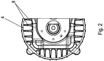
Figur 2 ist ein Querschnitt durch das Flanschteil 4 gezeigt. - In der
Figur 3 ist ein vergrößerter Ausschnitt eines Längsschnitts durch das Flanschteil 4 gezeigt. - In der
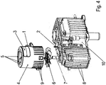
Figur 4 ist eine Schrägansicht auf das explodierte Getriebe dargestellt. - Wie in den Figuren gezeigt, weist das erfindungsgemäße Getriebe ein Gehäuseteil 10 auf, das mit einem Flanschteil 4 schraubverbunden ist.
- Das Flanschteil 4 ist im Wesentlichen hohlzylindrisch ausgeführt und umgibt die eintreibende Welle 7 und einen mit ihr drehfest verbundenen Lüfter 6.
- Am ersten axialen, also in Achsrichtung der eintreibenden Welle 7 gesehenen, Ende des Flanschteils 4 ist dieses mit dem Gehäuseteil 10 verbunden. Am anderen axialen Ende des Flanschteils 4 ist ein Adapter schraubverbindbar oder ein Elektromotor. Für diese Schraubverbindung weist das Flanschteil 4 Bohrungen 5 auf, die in Umfangsrichtung regelmäßig voneinander beabstandet sind und auf dem jeweils gleichen Radialabstand angeordnet sind.
- Das Gehäuseteil 10 weise Kühlrippen 8 auf, welche in axialer Richtung sich erstrecken und abgesetzt ausgeführt sind, also der Verlauf des größten Radialabstands der Kühlrippen 8 in axialer Richtung stufenförmig ist.
- Das Flanschteil 4 sitzt mit seinem ersten axialen Ende auf dieser so gebildeten Stufe beziehungsweise auf dem so gebildeten Absatz auf.
- Jeder axial sich erstreckenden Kühlrippe 8 des Gehäuseteils 10, welche im von dem Flanschteil 4 überdeckten Radialabstandsbereich angeordnet ist oder mit diesem überlappt, ist jeweils eine Erhebung 9 zugeordnet, die in derselben Umfangswinkelposition angeordnet ist wie die jeweils zugeordnete Kühlrippe 8. Der von der jeweiligen Erhebung 9 überdeckte Radialabstandsbereich überlappt mit dem von der zugeordneten Kühlrippe 8 jeweils überdeckte Radialabstandsbereich oder ist von diesem umfasst.
- Die Erhebungen 9 erstrecken sich ebenfalls in axialer Richtung, sind also parallel oder sogar koaxial ausgerichtet zu den jeweiligen Kühlrippen 8.
- An seiner Außenfläche weist das Flanschteil 4 eine Ausnehmung auf, die mittels eines Lochblechs 3 bedeckt ist. Somit ist der Lüfter als Axiallüfter ausführbar, welcher die Luft aus radialer Richtung kommend ansaugt und dann in axialer Richtung in die Zwischenräume zwischen des Kühlrippen 8 fördert.
- Somit wird die Luft seitlich angesaugt und in axialer Richtung parallel zur Erstreckungsrichtung der Kühlrippen 8 gefördert. Auf diese Weise ist ein effektives Kühlen des Gehäuseteils 10 ermöglicht. Aber auch das Flanschteil 4 wird durch die Erhebungen 9 entwärmt.
- Die eintreibende Welle 7 ist mittels Lager 30 im Gehäuseteil 10 gelagert und mittels einer berührungslosen Dichtung 31, insbesondere Labyrinthdichtung, abgedichtet. Allerdings ist diese Dichtung 31 zu schmieren, insbesondere mit Schmierfett.
- Wie in
Figur 4 gezeigt, ist hierzu eine Rohrleitung am Gehäuseteil 10 befestigt, welche zur Dichtung 31 führt. - An einem radial hervorkragenden Erkerabschnitt des Flanschteils 4 ist ein Anschlussmittel 1, insbesondere Schmiernippel, angeordnet.
- Vor Montage des Getriebes ist also das Anschlussmittel 1 vorkomplettiert am Flanschteil 4 angeordnet und mit diesem verbunden; die Rohrleitung 2 ist mit dem Gehäuseteil 10 vorkomplettiert und verbunden.
- Bei Montage des Getriebes wird das Flanschteil 4 aufgesetzt auf das Gehäuseteil 10, wobei das Flanschteil 4 am Absatz der Kühlrippen zum Anliegen kommen kann. Bei diesem Aufsetzen wird auch das Anschlussmittel 1mit der Rohrleitung dicht verbunden.
- Somit ist dann das Schmierfett für die berührungslose Dichtung am Flanschteil 4 hinzuführbar, obwohl die Rohrleitung 2 am Gehäuseteil 10 befestigt ist.
- Nach Aufsetzen des Flanschteils 4 auf den Absatz der Kühlrippen 8 umgibt das Flanschteil 4 den abgesetzten Bereich der Kühlrippen 8. Der vom Lüfter geförderte Luftstrom fließt dabei zwischen den Kühlrippen 8 und dem Flanschteil 4 hindurch. Der von dem Flanschteil 4 überdeckte axiale Bereich überlappt mit dem von den Kühlrippen 8 überdeckten axialen Bereich. Dabei ist der Überlappungsbereich in axialer Richtung weiter ausgedehnt als ein menschlicher Finger. Auf diese Weise wird verhindert, dass von außen drehende Teile durch einen Menschen berührbar sind.
- Der aus dem Zwischenraum zwischen Flanschteil 4 und Kühlrippen 8 austretende Luftstrom wird weiter entlang am Gehäuseteil 10 geführt, insbesondere zwischen den Kühlrippen 8 in axialer Richtung entlang. Somit ist ein effektives Kühlen des Gehäuseteils 10 ausführbar.
- Im Gehäuseteil 10 sind weitere Wellen, insbesondere auch die Abtriebswelle, gelagert. Die eintreibende Welle 7 ist mit einem Verzahnungsteil drehfest verbunden. Ebenso sind auch die weiteren Wellen jeweils mit zumindest einem Verzahnungsteil drehfest verbunden. Die im Eingriff stehenden Verzahnungsteile sind mittels Schmieröl geschmiert.
- Das Lochblech 3 ist mit derart kleinen Löchern ausgeführt, dass kein menschlicher Finger hindurchführbar ist.
- Nach Anbau des Adapters und/oder des Motors mittels Vorsehen von schrauben in den Bohrungen 5 ist die in
Figur 1 nach oben geöffnete Ausnehmung des Flanschteils 4 verschlossen. - Unter menschlichem Finger wird hierbei stets ein Finger mit den in einer Norm angegebenen Maßen verstanden.
- Die Rohrleitung 2 ist vorzugsweise aus einem biegbaren Material, wie Kupfer oder Stahl, ausführbar.
- Das Lochblech 3 ist vorzugsweise aus Stahlblech als Stanz-Biegeteil gefertigt.
- Das Flanschteil 4, insbesondere Laternenflansch, ist vorzugsweise aus Stahl gefertigt. Das Gehäuseteil 10 ist vorzugsweise aus Stahl oder Stahlguss hergestellt. Dabei ist auch eine mehrteilige Ausführung vorteilhaft, wenn die jeweiligen Einzelteile dicht miteinander verbunden sind. Alternativ ist das gehäuseteil 10 einteilig hergestellt, so dass der Aufwand für Dichtungen verringert ist, aber die Ausformung des Gehäuses 10 dann weniger komplex sein darf.
-
- 1
- Anschlussmittel, insbesondere Schmiernippel
- 2
- Rohrleitung
- 3
- Lochblech
- 4
- Flanschteil, insbesondere Laternenflansch
- 5
- Bohrungen
- 6
- Lüfter
- 7
- eintreibende Welle
- 8
- Kühlrippen
- 9
- Erhebungen, insbesondere Kühlrippen
- 10
- Gehäuseteil
- 30
- Lager
- 31
- berührungslose Dichtung, insbesondere Labyrinthdichtung
Claims (8)
- Getriebe, aufweisend eine eintreibende Welle (7) ein Flanschteil (4) und ein Gehäuseteil (10), das mit dem Flanschteil (4) schraubverbunden ist,
wobei die eintreibende Welle (7) mittels Lager (30) im Gehäuseteil (10) gelagert ist,
wobei ein Lüfter (6) mit der Welle (7) drehfest verbunden ist,
wobei das Gehäuseteil (10) Kühlrippen (8) aufweist, insbesondere welche sich in axialer Richtung, also Achsrichtung der Welle (7), erstrecken,
wobei die Kühlrippen (8) gestuft ausgeführt sind,
wobei das Flanschteil (4) den gestuften Bereich der Kühlrippen (8) umgibt, insbesondere gehäusebildend umgibt,
dadurch gekennzeichnet, dass
jeder Kühlrippe (8), die am Gehäuseteil (10) angeordnet ist und deren überdeckter Radialabstandsbereich mit dem von dem Flanschteil (4) überdeckten Radialabstandsbereich überlappt, eine am Flanschteil (4) angeordnete Erhebung (9) zugeordnet ist, insbesondere eineindeutig zugeordnet ist,
wobei die jeweilige Erhebung (9) an derselben Umfangswinkelposition angeordnet ist wie die jeweils zugeordnete Kühlrippe (8). - Getriebe nach Anspruch 1,
dadurch gekennzeichnet, dass
der vom Lüfter (6) geförderte Luftstrom zwischen dem Flanschteil (4) und den Kühlrippen (8) hindurchströmt. - Getriebe nach mindestens einem der vorangegangenen Ansprüche,
dadurch gekennzeichnet, dass
das Flanschteil (4) an seiner Außenfläche eine Ausnehmung aufweist, durch welche der Luftstrom eintritt. - Getriebe nach mindestens einem der vorangegangenen Ansprüche,
dadurch gekennzeichnet, dass
die Ausnehmung mit einem Lochblech (3) verschlossen ist, das mit dem Flanschteil (4) verbunden ist, insbesondere schraubverbunden,
insbesondere wobei der Durchmesser der Löcher kleiner als der Durchmesser eines menschlichen Fingers ist. - Getriebe nach mindestens einem der vorangegangenen Ansprüche,
dadurch gekennzeichnet, dass
der vom Flanschteil (4) überdeckte axiale Bereich mit dem von den Kühlrippen (8) überdeckten axialen Bereich überlappt,
insbesondere wobei der Überlappungsbereich weiter ausgedehnt ist als die Länge eines menschlichen Fingers. - Getriebe nach mindestens einem der vorangegangenen Ansprüche,
dadurch gekennzeichnet, dass
die jeweilige Erhebung als Kühlrippe ausgeführt ist, insbesondere am Flanschteil (4) ausgeformt ist. - Getriebe nach mindestens einem der vorangegangenen Ansprüche,
dadurch gekennzeichnet, dass
am Flanschteil (4) ein Anschlussmittel (1), insbesondere Schmiernippel, befestigt ist,
wobei am Gehäuseteil (10) eine Rohrleitung (2) befestigt ist. - Getriebe nach mindestens einem der vorangegangenen Ansprüche,
dadurch gekennzeichnet, dass
das Flanschteil (4) auf die Stufe aufgesetzt angeordnet ist.
Applications Claiming Priority (3)
| Application Number | Priority Date | Filing Date | Title |
|---|---|---|---|
| DE102015004509 | 2015-04-13 | ||
| DE102015011163.9A DE102015011163B4 (de) | 2015-04-13 | 2015-09-01 | Getriebe, aufweisend eine Welle, ein Flanschteil und ein Gehäuseteil |
| PCT/EP2016/000400 WO2016165802A1 (de) | 2015-04-13 | 2016-03-07 | Getriebe, aufweisend eine welle, ein flanschteil und ein gehäuseteil |
Publications (2)
| Publication Number | Publication Date |
|---|---|
| EP3283793A1 EP3283793A1 (de) | 2018-02-21 |
| EP3283793B1 true EP3283793B1 (de) | 2021-08-18 |
Family
ID=56986067
Family Applications (1)
| Application Number | Title | Priority Date | Filing Date |
|---|---|---|---|
| EP16709700.5A Active EP3283793B1 (de) | 2015-04-13 | 2016-03-07 | Getriebe, aufweisend eine welle, ein flanschteil und ein gehäuseteil |
Country Status (5)
| Country | Link |
|---|---|
| US (1) | US10539223B2 (de) |
| EP (1) | EP3283793B1 (de) |
| CN (1) | CN107438729B (de) |
| DE (1) | DE102015011163B4 (de) |
| WO (1) | WO2016165802A1 (de) |
Families Citing this family (5)
| Publication number | Priority date | Publication date | Assignee | Title |
|---|---|---|---|---|
| US10995846B2 (en) * | 2016-09-23 | 2021-05-04 | Bell Helicopter Textron Inc. | Fan with labyrinth seal for prevention of water damage to a gearbox |
| CN107401600A (zh) * | 2017-08-30 | 2017-11-28 | 江苏泰隆减速机股份有限公司 | 一种便于散热的工业机器人用减速机 |
| US10458534B1 (en) * | 2018-05-31 | 2019-10-29 | Abb Schweiz Ag | Gearbox system with add-on cooling fin panels |
| AU2020317435B2 (en) * | 2019-07-19 | 2023-11-09 | Sew-Eurodrive Gmbh & Co. Kg | Gear motor, comprising a gear mechanism driven via a clutch by an electric motor |
| JP7373987B2 (ja) * | 2019-12-26 | 2023-11-06 | 住友重機械工業株式会社 | 直交減速装置 |
Family Cites Families (16)
| Publication number | Priority date | Publication date | Assignee | Title |
|---|---|---|---|---|
| US2786614A (en) * | 1954-08-26 | 1957-03-26 | Joseph F Giusto | Attachment for paint cans or the like |
| US2756614A (en) * | 1954-08-30 | 1956-07-31 | Illinois Tool Works | Gearing unit |
| US3417636A (en) * | 1966-04-25 | 1968-12-24 | Randolph Mfg Company | Heat transfer apparatus |
| DE1298819B (de) | 1966-07-21 | 1969-07-03 | Wuelfel Eisenwerk | Kuehlvorrichtung fuer Umlaufraedergetriebe |
| US4414861A (en) * | 1982-02-17 | 1983-11-15 | The Falk Corporation | Gear drive cooling |
| DE3331038A1 (de) | 1983-08-29 | 1985-03-14 | Dorstener Maschinenfabrik Ag, 4270 Dorsten | Verzweigungsgetriebe mit kuehlmantel |
| RO99709B1 (ro) | 1989-05-03 | 1991-06-01 | îNTREPRINDEREA DE MOTOARE ELECTRICE | Carcasa din tabla pentru motoare electrice |
| DE19607882C1 (de) | 1996-03-01 | 1997-02-27 | Kaercher Gmbh & Co Alfred | Hochdruckreinigungsgerät |
| DE19853459B4 (de) | 1998-11-19 | 2005-11-24 | Sew-Eurodrive Gmbh & Co. Kg | Planetengetriebe |
| DE102004030180A1 (de) * | 2004-06-22 | 2006-02-09 | A. Friedr. Flender Ag | Stirnradgetriebe |
| DE102008017643B4 (de) * | 2008-04-04 | 2016-09-15 | Sew-Eurodrive Gmbh & Co Kg | Adapter, Getriebe und Antrieb |
| DE102008017755A1 (de) | 2008-04-07 | 2009-10-15 | Sew-Eurodrive Gmbh & Co. Kg | Kühlanordnung für ein Getriebe, Getriebe und Antrieb |
| DE102009014314B4 (de) | 2009-03-25 | 2024-05-16 | Sew-Eurodrive Gmbh & Co Kg | Getriebe |
| CN202048174U (zh) * | 2011-05-11 | 2011-11-23 | Sew-工业减速机(天津)有限公司 | 减速器装置 |
| DE102012000682B4 (de) * | 2012-01-17 | 2024-03-21 | Sew-Eurodrive Gmbh & Co Kg | Lüfteranordnung für ein Getriebe und Getriebe mit einer Lüfteranordnung |
| DE102012025596A1 (de) | 2012-07-06 | 2014-01-09 | Sew-Eurodrive Gmbh & Co Kg | Getriebe mit einer Welle |
-
2015
- 2015-09-01 DE DE102015011163.9A patent/DE102015011163B4/de active Active
-
2016
- 2016-03-07 EP EP16709700.5A patent/EP3283793B1/de active Active
- 2016-03-07 US US15/566,562 patent/US10539223B2/en active Active
- 2016-03-07 WO PCT/EP2016/000400 patent/WO2016165802A1/de not_active Ceased
- 2016-03-07 CN CN201680021429.6A patent/CN107438729B/zh active Active
Also Published As
| Publication number | Publication date |
|---|---|
| DE102015011163B4 (de) | 2022-07-14 |
| US20180119794A1 (en) | 2018-05-03 |
| EP3283793A1 (de) | 2018-02-21 |
| DE102015011163A1 (de) | 2016-10-13 |
| CN107438729B (zh) | 2020-02-07 |
| CN107438729A (zh) | 2017-12-05 |
| WO2016165802A1 (de) | 2016-10-20 |
| US10539223B2 (en) | 2020-01-21 |
Similar Documents
| Publication | Publication Date | Title |
|---|---|---|
| EP2286502B1 (de) | Spindelmotor | |
| DE102015011163B4 (de) | Getriebe, aufweisend eine Welle, ein Flanschteil und ein Gehäuseteil | |
| DE102016204519B4 (de) | Nasslaufendes Zugmittelgetriebe | |
| EP2834538B1 (de) | Getriebe mit einem ersten und einem zweiten gehäuseteil | |
| EP3595954B1 (de) | Getriebe, insbesondere für antriebsstrang von schienenfahrzeugen | |
| EP3268634A1 (de) | Getriebe mit einer planetengetriebestufe | |
| EP3772159A1 (de) | Elektromechanische antriebseinheit, insbesondere einzelradantriebseinheit | |
| DE102014017696B4 (de) | Getriebe, dessen Innenraum zumindest teilweise mit Schmieröl befüllt ist | |
| EP3924646B1 (de) | Antriebssystem, aufweisend einen elektromotor, ein getriebe und einen einen lüfter aufweisenden adapter | |
| DE102019213949B3 (de) | Vorrichtung zum Fördern von Schmiermittel | |
| WO2013091769A2 (de) | Antrieb, umfassend getriebemotor | |
| DE102014009317B4 (de) | Antrieb | |
| EP3999753B1 (de) | Getriebemotor, aufweisend ein über eine kupplung von einem elektromotor angetriebenes getriebe | |
| DE102012008895A1 (de) | Getriebe mit einem Getriebegehäuseteil | |
| EP3353451B1 (de) | Getriebe mit einer rohrleitung | |
| DE102014005002B4 (de) | Antriebssystem für eine Last | |
| DE102015204092A1 (de) | Getriebe sowie Kraftfahrzeug | |
| DE102018102572A1 (de) | Drehmomentübertragungseinrichtung | |
| DE102023004609A1 (de) | Lageranordnung, insbesondere für einen Elektromotor oder für ein Getriebe, und Elektromotor mit Lageranordnung | |
| EP4552207A1 (de) | Elektromotor mit lüfter | |
| DE102012216238A1 (de) | Kupplung und Kupplungsnabe | |
| EP4565804A1 (de) | Antriebsanordnung und fahrzeug mit einer solchen antriebsanordnung | |
| DE102020107535A1 (de) | Hohlwelleneinrichtung mit passiver Flüssigkeitsversorgung und Antriebsvorrichtung mit Hohlwelleneinrichtung | |
| DE102016211433A1 (de) | Wellendichtungssystem und Pumpenanordnung mit einem derartigen Wellendichtungssystem |
Legal Events
| Date | Code | Title | Description |
|---|---|---|---|
| STAA | Information on the status of an ep patent application or granted ep patent |
Free format text: STATUS: THE INTERNATIONAL PUBLICATION HAS BEEN MADE |
|
| PUAI | Public reference made under article 153(3) epc to a published international application that has entered the european phase |
Free format text: ORIGINAL CODE: 0009012 |
|
| STAA | Information on the status of an ep patent application or granted ep patent |
Free format text: STATUS: REQUEST FOR EXAMINATION WAS MADE |
|
| 17P | Request for examination filed |
Effective date: 20171113 |
|
| AK | Designated contracting states |
Kind code of ref document: A1 Designated state(s): AL AT BE BG CH CY CZ DE DK EE ES FI FR GB GR HR HU IE IS IT LI LT LU LV MC MK MT NL NO PL PT RO RS SE SI SK SM TR |
|
| AX | Request for extension of the european patent |
Extension state: BA ME |
|
| DAV | Request for validation of the european patent (deleted) | ||
| DAX | Request for extension of the european patent (deleted) | ||
| GRAP | Despatch of communication of intention to grant a patent |
Free format text: ORIGINAL CODE: EPIDOSNIGR1 |
|
| STAA | Information on the status of an ep patent application or granted ep patent |
Free format text: STATUS: GRANT OF PATENT IS INTENDED |
|
| INTG | Intention to grant announced |
Effective date: 20210408 |
|
| GRAS | Grant fee paid |
Free format text: ORIGINAL CODE: EPIDOSNIGR3 |
|
| GRAA | (expected) grant |
Free format text: ORIGINAL CODE: 0009210 |
|
| STAA | Information on the status of an ep patent application or granted ep patent |
Free format text: STATUS: THE PATENT HAS BEEN GRANTED |
|
| AK | Designated contracting states |
Kind code of ref document: B1 Designated state(s): AL AT BE BG CH CY CZ DE DK EE ES FI FR GB GR HR HU IE IS IT LI LT LU LV MC MK MT NL NO PL PT RO RS SE SI SK SM TR |
|
| REG | Reference to a national code |
Ref country code: GB Ref legal event code: FG4D Free format text: NOT ENGLISH |
|
| REG | Reference to a national code |
Ref country code: CH Ref legal event code: EP |
|
| REG | Reference to a national code |
Ref country code: DE Ref legal event code: R096 Ref document number: 502016013648 Country of ref document: DE |
|
| REG | Reference to a national code |
Ref country code: IE Ref legal event code: FG4D Free format text: LANGUAGE OF EP DOCUMENT: GERMAN Ref country code: AT Ref legal event code: REF Ref document number: 1421929 Country of ref document: AT Kind code of ref document: T Effective date: 20210915 |
|
| REG | Reference to a national code |
Ref country code: LT Ref legal event code: MG9D |
|
| REG | Reference to a national code |
Ref country code: NL Ref legal event code: MP Effective date: 20210818 |
|
| PG25 | Lapsed in a contracting state [announced via postgrant information from national office to epo] |
Ref country code: RS Free format text: LAPSE BECAUSE OF FAILURE TO SUBMIT A TRANSLATION OF THE DESCRIPTION OR TO PAY THE FEE WITHIN THE PRESCRIBED TIME-LIMIT Effective date: 20210818 Ref country code: SE Free format text: LAPSE BECAUSE OF FAILURE TO SUBMIT A TRANSLATION OF THE DESCRIPTION OR TO PAY THE FEE WITHIN THE PRESCRIBED TIME-LIMIT Effective date: 20210818 Ref country code: BG Free format text: LAPSE BECAUSE OF FAILURE TO SUBMIT A TRANSLATION OF THE DESCRIPTION OR TO PAY THE FEE WITHIN THE PRESCRIBED TIME-LIMIT Effective date: 20211118 Ref country code: LT Free format text: LAPSE BECAUSE OF FAILURE TO SUBMIT A TRANSLATION OF THE DESCRIPTION OR TO PAY THE FEE WITHIN THE PRESCRIBED TIME-LIMIT Effective date: 20210818 Ref country code: PT Free format text: LAPSE BECAUSE OF FAILURE TO SUBMIT A TRANSLATION OF THE DESCRIPTION OR TO PAY THE FEE WITHIN THE PRESCRIBED TIME-LIMIT Effective date: 20211220 Ref country code: NO Free format text: LAPSE BECAUSE OF FAILURE TO SUBMIT A TRANSLATION OF THE DESCRIPTION OR TO PAY THE FEE WITHIN THE PRESCRIBED TIME-LIMIT Effective date: 20211118 Ref country code: ES Free format text: LAPSE BECAUSE OF FAILURE TO SUBMIT A TRANSLATION OF THE DESCRIPTION OR TO PAY THE FEE WITHIN THE PRESCRIBED TIME-LIMIT Effective date: 20210818 Ref country code: FI Free format text: LAPSE BECAUSE OF FAILURE TO SUBMIT A TRANSLATION OF THE DESCRIPTION OR TO PAY THE FEE WITHIN THE PRESCRIBED TIME-LIMIT Effective date: 20210818 Ref country code: HR Free format text: LAPSE BECAUSE OF FAILURE TO SUBMIT A TRANSLATION OF THE DESCRIPTION OR TO PAY THE FEE WITHIN THE PRESCRIBED TIME-LIMIT Effective date: 20210818 |
|
| PG25 | Lapsed in a contracting state [announced via postgrant information from national office to epo] |
Ref country code: PL Free format text: LAPSE BECAUSE OF FAILURE TO SUBMIT A TRANSLATION OF THE DESCRIPTION OR TO PAY THE FEE WITHIN THE PRESCRIBED TIME-LIMIT Effective date: 20210818 Ref country code: LV Free format text: LAPSE BECAUSE OF FAILURE TO SUBMIT A TRANSLATION OF THE DESCRIPTION OR TO PAY THE FEE WITHIN THE PRESCRIBED TIME-LIMIT Effective date: 20210818 Ref country code: GR Free format text: LAPSE BECAUSE OF FAILURE TO SUBMIT A TRANSLATION OF THE DESCRIPTION OR TO PAY THE FEE WITHIN THE PRESCRIBED TIME-LIMIT Effective date: 20211119 |
|
| PG25 | Lapsed in a contracting state [announced via postgrant information from national office to epo] |
Ref country code: NL Free format text: LAPSE BECAUSE OF FAILURE TO SUBMIT A TRANSLATION OF THE DESCRIPTION OR TO PAY THE FEE WITHIN THE PRESCRIBED TIME-LIMIT Effective date: 20210818 |
|
| PG25 | Lapsed in a contracting state [announced via postgrant information from national office to epo] |
Ref country code: DK Free format text: LAPSE BECAUSE OF FAILURE TO SUBMIT A TRANSLATION OF THE DESCRIPTION OR TO PAY THE FEE WITHIN THE PRESCRIBED TIME-LIMIT Effective date: 20210818 |
|
| REG | Reference to a national code |
Ref country code: DE Ref legal event code: R097 Ref document number: 502016013648 Country of ref document: DE |
|
| PG25 | Lapsed in a contracting state [announced via postgrant information from national office to epo] |
Ref country code: SM Free format text: LAPSE BECAUSE OF FAILURE TO SUBMIT A TRANSLATION OF THE DESCRIPTION OR TO PAY THE FEE WITHIN THE PRESCRIBED TIME-LIMIT Effective date: 20210818 Ref country code: SK Free format text: LAPSE BECAUSE OF FAILURE TO SUBMIT A TRANSLATION OF THE DESCRIPTION OR TO PAY THE FEE WITHIN THE PRESCRIBED TIME-LIMIT Effective date: 20210818 Ref country code: RO Free format text: LAPSE BECAUSE OF FAILURE TO SUBMIT A TRANSLATION OF THE DESCRIPTION OR TO PAY THE FEE WITHIN THE PRESCRIBED TIME-LIMIT Effective date: 20210818 Ref country code: EE Free format text: LAPSE BECAUSE OF FAILURE TO SUBMIT A TRANSLATION OF THE DESCRIPTION OR TO PAY THE FEE WITHIN THE PRESCRIBED TIME-LIMIT Effective date: 20210818 Ref country code: CZ Free format text: LAPSE BECAUSE OF FAILURE TO SUBMIT A TRANSLATION OF THE DESCRIPTION OR TO PAY THE FEE WITHIN THE PRESCRIBED TIME-LIMIT Effective date: 20210818 Ref country code: AL Free format text: LAPSE BECAUSE OF FAILURE TO SUBMIT A TRANSLATION OF THE DESCRIPTION OR TO PAY THE FEE WITHIN THE PRESCRIBED TIME-LIMIT Effective date: 20210818 |
|
| PLBE | No opposition filed within time limit |
Free format text: ORIGINAL CODE: 0009261 |
|
| STAA | Information on the status of an ep patent application or granted ep patent |
Free format text: STATUS: NO OPPOSITION FILED WITHIN TIME LIMIT |
|
| 26N | No opposition filed |
Effective date: 20220519 |
|
| PG25 | Lapsed in a contracting state [announced via postgrant information from national office to epo] |
Ref country code: SI Free format text: LAPSE BECAUSE OF FAILURE TO SUBMIT A TRANSLATION OF THE DESCRIPTION OR TO PAY THE FEE WITHIN THE PRESCRIBED TIME-LIMIT Effective date: 20210818 |
|
| PG25 | Lapsed in a contracting state [announced via postgrant information from national office to epo] |
Ref country code: MC Free format text: LAPSE BECAUSE OF FAILURE TO SUBMIT A TRANSLATION OF THE DESCRIPTION OR TO PAY THE FEE WITHIN THE PRESCRIBED TIME-LIMIT Effective date: 20210818 |
|
| REG | Reference to a national code |
Ref country code: CH Ref legal event code: PL |
|
| GBPC | Gb: european patent ceased through non-payment of renewal fee |
Effective date: 20220307 |
|
| PG25 | Lapsed in a contracting state [announced via postgrant information from national office to epo] |
Ref country code: LU Free format text: LAPSE BECAUSE OF NON-PAYMENT OF DUE FEES Effective date: 20220307 Ref country code: LI Free format text: LAPSE BECAUSE OF NON-PAYMENT OF DUE FEES Effective date: 20220331 Ref country code: IE Free format text: LAPSE BECAUSE OF NON-PAYMENT OF DUE FEES Effective date: 20220307 Ref country code: GB Free format text: LAPSE BECAUSE OF NON-PAYMENT OF DUE FEES Effective date: 20220307 Ref country code: FR Free format text: LAPSE BECAUSE OF NON-PAYMENT OF DUE FEES Effective date: 20220331 Ref country code: CH Free format text: LAPSE BECAUSE OF NON-PAYMENT OF DUE FEES Effective date: 20220331 |
|
| REG | Reference to a national code |
Ref country code: AT Ref legal event code: MM01 Ref document number: 1421929 Country of ref document: AT Kind code of ref document: T Effective date: 20220307 |
|
| PG25 | Lapsed in a contracting state [announced via postgrant information from national office to epo] |
Ref country code: AT Free format text: LAPSE BECAUSE OF NON-PAYMENT OF DUE FEES Effective date: 20220307 |
|
| PG25 | Lapsed in a contracting state [announced via postgrant information from national office to epo] |
Ref country code: HU Free format text: LAPSE BECAUSE OF FAILURE TO SUBMIT A TRANSLATION OF THE DESCRIPTION OR TO PAY THE FEE WITHIN THE PRESCRIBED TIME-LIMIT; INVALID AB INITIO Effective date: 20160307 |
|
| PG25 | Lapsed in a contracting state [announced via postgrant information from national office to epo] |
Ref country code: MK Free format text: LAPSE BECAUSE OF FAILURE TO SUBMIT A TRANSLATION OF THE DESCRIPTION OR TO PAY THE FEE WITHIN THE PRESCRIBED TIME-LIMIT Effective date: 20210818 Ref country code: CY Free format text: LAPSE BECAUSE OF FAILURE TO SUBMIT A TRANSLATION OF THE DESCRIPTION OR TO PAY THE FEE WITHIN THE PRESCRIBED TIME-LIMIT Effective date: 20210818 |
|
| PG25 | Lapsed in a contracting state [announced via postgrant information from national office to epo] |
Ref country code: TR Free format text: LAPSE BECAUSE OF FAILURE TO SUBMIT A TRANSLATION OF THE DESCRIPTION OR TO PAY THE FEE WITHIN THE PRESCRIBED TIME-LIMIT Effective date: 20210818 |
|
| PG25 | Lapsed in a contracting state [announced via postgrant information from national office to epo] |
Ref country code: MT Free format text: LAPSE BECAUSE OF FAILURE TO SUBMIT A TRANSLATION OF THE DESCRIPTION OR TO PAY THE FEE WITHIN THE PRESCRIBED TIME-LIMIT Effective date: 20210818 |
|
| PGFP | Annual fee paid to national office [announced via postgrant information from national office to epo] |
Ref country code: DE Payment date: 20260331 Year of fee payment: 11 |
|
| PGFP | Annual fee paid to national office [announced via postgrant information from national office to epo] |
Ref country code: BE Payment date: 20260330 Year of fee payment: 11 Ref country code: IT Payment date: 20260128 Year of fee payment: 11 |