EP3283370B1 - Halter für portable elektronische geräte - Google Patents
Halter für portable elektronische geräte Download PDFInfo
- Publication number
- EP3283370B1 EP3283370B1 EP15719869.8A EP15719869A EP3283370B1 EP 3283370 B1 EP3283370 B1 EP 3283370B1 EP 15719869 A EP15719869 A EP 15719869A EP 3283370 B1 EP3283370 B1 EP 3283370B1
- Authority
- EP
- European Patent Office
- Prior art keywords
- electronic device
- portable electronic
- clamping structure
- flap
- clamping
- Prior art date
- Legal status (The legal status is an assumption and is not a legal conclusion. Google has not performed a legal analysis and makes no representation as to the accuracy of the status listed.)
- Active
Links
- 239000012780 transparent material Substances 0.000 claims description 10
- 210000003739 neck Anatomy 0.000 description 2
- 238000010186 staining Methods 0.000 description 2
- 230000000712 assembly Effects 0.000 description 1
- 238000000429 assembly Methods 0.000 description 1
- 230000008878 coupling Effects 0.000 description 1
- 238000010168 coupling process Methods 0.000 description 1
- 238000005859 coupling reaction Methods 0.000 description 1
- 230000001419 dependent effect Effects 0.000 description 1
- 235000012054 meals Nutrition 0.000 description 1
Images


Classifications
-
- B—PERFORMING OPERATIONS; TRANSPORTING
- B60—VEHICLES IN GENERAL
- B60N—SEATS SPECIALLY ADAPTED FOR VEHICLES; VEHICLE PASSENGER ACCOMMODATION NOT OTHERWISE PROVIDED FOR
- B60N3/00—Arrangements or adaptations of other passenger fittings, not otherwise provided for
- B60N3/001—Arrangements or adaptations of other passenger fittings, not otherwise provided for of tables or trays
- B60N3/002—Arrangements or adaptations of other passenger fittings, not otherwise provided for of tables or trays of trays
- B60N3/004—Arrangements or adaptations of other passenger fittings, not otherwise provided for of tables or trays of trays of foldable trays mounted on the back-rest
-
- B—PERFORMING OPERATIONS; TRANSPORTING
- B64—AIRCRAFT; AVIATION; COSMONAUTICS
- B64D—EQUIPMENT FOR FITTING IN OR TO AIRCRAFT; FLIGHT SUITS; PARACHUTES; ARRANGEMENT OR MOUNTING OF POWER PLANTS OR PROPULSION TRANSMISSIONS IN AIRCRAFT
- B64D11/00—Passenger or crew accommodation; Flight-deck installations not otherwise provided for
- B64D11/0015—Arrangements for entertainment or communications, e.g. radio, television
- B64D11/00152—Seat back fixtures for removable monitors, e.g. tablet computers
-
- B—PERFORMING OPERATIONS; TRANSPORTING
- B64—AIRCRAFT; AVIATION; COSMONAUTICS
- B64D—EQUIPMENT FOR FITTING IN OR TO AIRCRAFT; FLIGHT SUITS; PARACHUTES; ARRANGEMENT OR MOUNTING OF POWER PLANTS OR PROPULSION TRANSMISSIONS IN AIRCRAFT
- B64D11/00—Passenger or crew accommodation; Flight-deck installations not otherwise provided for
- B64D11/0015—Arrangements for entertainment or communications, e.g. radio, television
-
- B—PERFORMING OPERATIONS; TRANSPORTING
- B64—AIRCRAFT; AVIATION; COSMONAUTICS
- B64D—EQUIPMENT FOR FITTING IN OR TO AIRCRAFT; FLIGHT SUITS; PARACHUTES; ARRANGEMENT OR MOUNTING OF POWER PLANTS OR PROPULSION TRANSMISSIONS IN AIRCRAFT
- B64D11/00—Passenger or crew accommodation; Flight-deck installations not otherwise provided for
- B64D11/06—Arrangements of seats, or adaptations or details specially adapted for aircraft seats
- B64D11/0638—Arrangements of seats, or adaptations or details specially adapted for aircraft seats with foldable tables, trays or cup holders
Definitions
- the present invention relates generally to a portable electronic device holder for a passenger seat and an integrated entertainment system for a passenger seat.
- PEDs portable electronic devices
- IFE In-Flight Entertainment
- a seat is provided with an IFE monitor, passengers will have limited places where they can place their PEDs. They can either place their PEDs on the tray tables or in a removable pouch that is stuck to the top of the seat back. However, usage of their PEDs in these locations is limited.
- Fig. 1 shows a schematic 100 illustrating a portable electronic device placed on a tray table.
- a passenger seat 102 is provided with a tray table 104, on which a portable electronic device 106 can be placed.
- passengers are not able to use the portable electronic device 106 when the table 104 is stowed or when meals are being served.
- the viewing angle of the portable electronic device 106 is limited when placed on the table 104.
- Fig. 2 shows a schematic 200 illustrating a portable electronic device placed in a removable pouch.
- a removable pouch 204 is attached to the seat back of a passenger seat 202, and a portable electronic device 206 is placed in the pouch 204.
- viewing angle of the portable electronic device 206 is highly dependent on the backrest recline angle.
- the pouches that are typically provided by airlines can be easily taken away by passengers.
- FIG. 3 shows a schematic 300 illustrating a portable electronic device placed at the location of the IFE monitor.
- the portable electronic device 306 is placed in the location of the passenger chair 302 where the IFE monitor should be, and is held by a holder 304 including a base support to support the portable electronic device 306 and a grip on top to hold the portable electronic device 306 inbetween.
- DE 10 2012 112 942 A1 describes a securing device on an aircraft seat, said device comprising at least one seat component and at least one securing unit, which is at least partially positioned on the seat component and is designed to secure at least one tablet PC on the seat component so that said PC can be exchanged and operated.
- WO 2015/010123 A1 describes adjustable support assemblies that include a base, a support platform elastically coupled to the base, and a slide bar elastically coupled to a pair of tracks on the base, wherein the adjustable support assembly is positioned within a recess of a passenger seat back and at least partially surrounded by a shroud so that only portions of the support platform and the slide bar extend through the shroud, wherein the adjustable support assembly is configured to securely hold portable electronic devices having a range of heights, widths, and thicknesses.
- EP 2 746 158 A1 describes an aircraft seat with an aircraft seat holding device, with at least one backrest, with at least one aircraft seat carrier unit that is embodied by a backrest bridge and comprises, respectively on a righthand side and a lefthand side of the backrest, a connection region in which the aircraft seat carrier unit that is embodied as a backrest bridge is respectively connected to the backrest, the aircraft seat carrier unit comprising between the two connection regions a middle region, with a literature pocket having an opening via which literature and other objects are introduisible into the literature pocket, and with at least one fastening unit, which is configured for fastening a PED to the backrest in an exchangeable and operable manner in at least one operating state, the fastening unit being at least partially integrated in the aircraft seat carrier unit that is embodied as a backrest bridge.
- the present invention provides a portable electronic device holder for a passenger seat as defined in claims 1 to 12.
- a portable electronic device holder for a passenger seat including a planar support, and a longitudinal clamping structure attached to the planar support.
- the clamping structure has a generally L-shaped cross-section and is configured to hold the portable electronic device between the clamping structure and the planar support.
- the clamping structure includes a supporting flap forming an L-base of the generally L-shaped clamping structure and configured to support the portable electronic device, and a clamping flap forming an L-leg of the generally L-shaped clamping structure and configured to clamp the portable electronic device against the planar support.
- the portable electronic device holder further includes a mounting element for slidably or tiltably mounting the portable electronic holder to the passenger seat.
- an integrated entertainment system including a monitor mounted to a back of the passenger seat, and a longitudinal clamping structure mounted to the monitor.
- the clamping structure has a generally L-shaped cross-section and is configured to hold a portable electronic device between the monitor and the clamping structure.
- the clamping structure includes a supporting flap forming an L-base of the generally L-shaped clamping structure, and configured to support the portable electronic device, and a clamping flap forming an L-leg of the generally L-shaped clamping structure, and configured to clamp the portable electronic device against the monitor.
- the integrated entertainment system further includes a mounting element for slidably or tiltably mounting the clamping structure to the monitor.
- Various embodiments provide a portable electronic device holder for a passenger seat, for example, an aircraft seat.
- exemplary is used herein to mean “serving as an example, instance, or illustration”. Any embodiment or design described herein as “exemplary” is not necessarily to be construed as preferred or advantageous over other embodiments or designs.
- Fig. 4 shows a portable electronic device (PED) holder 400 for a passenger seat according to various embodiments.
- the PED holder includes a longitudinal clamping structure 420 having a generally L-shaped cross-section as shown in Fig. 4 .
- the clamping structure 420 includes a supporting flap 422 forming an L-base of the generally L-shaped clamping structure 420 and configured to support a portable electronic device (not shown).
- the clamping structure 420 include a clamping flap 424 forming an L-leg of the generally L-shaped clamping structure 420 and configured to clamp the portable electronic device against a surface abutting the portable electronic device.
- the portable electronic device holder 400 further includes a mounting element 410 for slidably mounting the clamping structure 420 to the passenger seat (not shown).
- the clamping structure 420 is configured to be mounted to a back of the passenger seat slidably in a direction 430 at least substantially perpendicular to a plane of the back of the seat to adjust a space between the clamping flap 424 and the surface abutting the portable electronic device.
- the direction 430 at least substantially perpendicular to the plane of the back of the seat is also referred to as a translational direction 430 in this context.
- the mounting element 410 may be a strip-like structure for slidably mounting the clamping structure 420 to the passenger seat, e.g. by coupling or inserting into a guide provided at the passenger seat.
- the mounting element 410 is provided for tiltably mounting the clamping structure 420 to the passenger seat.
- the mounting element 410 may include a hinge for tiltably mounting the clamping structure 420 to the passenger seat.
- the clamping structure 420 is tiltable relative to the back of the passenger seat to adjust a viewing angle of the portable electronic device.
- Fig. 5 shows a side view of a portable electronic device (PED) holder 500 for a passenger seat according to various embodiments. Similar to Fig. 4 , the PED holder 500 may include a longitudinal clamping structure 520 having a generally L-shaped cross-section as shown in Fig. 5 .
- the clamping structure 520 includes a supporting flap 522 forming an L-base of the generally L-shaped clamping structure 520 and configured to support a portable electronic device (not shown).
- the clamping structure 520 includes a clamping flap 524 forming an L-leg of the generally L-shaped clamping structure 520 and configured to clamp the portable electronic device against a surface abutting the portable electronic device.
- the portable electronic device holder 500 further includes a mounting element 510 for tiltably mounting the clamping structure 520 to the passenger seat (not shown).
- the mounting element 510 is provided for tiltably mounting the clamping structure 520 to the passenger seat.
- the clamping structure 520 is tiltable relative to the back of the passenger seat in a rotational direction 540 to adjust a viewing angle of the portable electronic device.
- the tiltable PED holder allows the passenger to adjust the PED holder's viewing angle in order to compensate the change in viewing angle when the backrest in front of the passenger changes it recline angle.
- the PED holder may be placed at the upper section of the seatback, which will allow passengers to look at their PED comfortably without staining their necks.
- the surface abutting the portable electronic device may be the seat back of the passenger seat, for example, when the PED holder 400, 500 is directly mounted to the seat back of the passenger seat.
- the surface abutting the portable electronic device may be a monitor, for example, an in-flight entertainment (IFE) monitor mounted to the passenger seat.
- the surface abutting the portable electronic device may be a planar support, which may be mounted to the passenger seat directly or through the clamping structure 520.
- the mounting element 410,510 may be integrally formed together with the supporting flap 422, 522 of the clamping structure 420, 520. In other embodiments, the mounting element 410, 510 may be connected to the clamping structure 420, 520, e.g. the mounting element 410, 510 may be separate pieces which is joined or connected to the clamping structure 420, 520.
- a flap refers to a generally flat piece with a longitudinal shape or strip shape.
- the supporting flap may be a strip-like structure having a flat and longitudinal top surface for supporting and receiving the portable electronic device thereon, e.g. the supporting flap 422, 522 as shown in Fig. 4 and Fig. 5 for supporting the portable electronic device standing on the top surface of the supporting flap.
- the clamping flap may be a longitudinal structure having a flat surface, e.g. the clamping flap 424 as shown in Fig. 4 and Fig. 8 below.
- the clamping flap may be a longitudinal structure having a curved shape or cross-section, e.g. the clamping flap 524 as shown in Fig. 5 and Fig. 9 below.
- the clamping flap and the supporting are pivotably connected to each other at their longitudinal edges.
- the clamping flap is configured to clamp or abut a front plane of the portable electronic device against the surface abutting a back plane of the portable electronic device when the portable electronic device is supported on the supporting flap.
- the clamping flap 424, 524 is pivotably coupled to the supporting flap 422, 522 through a hinge, e.g. the hinge 526 shown in Fig. 5 .
- the clamping flap 424, 524 may be pivotable to adjust a space between the clamping flap 424, 524 and the surface abutting the portable electronic device.
- the clamping flap 424, 524 may be formed as a single flap, or may be formed by a plurality of portions connected by interconnecting portions (e.g. as shown in Fig. 4 ), or may be formed by a plurality of portions separated from each other.
- the clamping flap 424, 524 may be made of transparent material, to prevent or minimize blockage of the effective area (e.g. the screen) of the PED.
- the entire clamping structure 420, 520 may be made of transparent material, for example, to prevent or minimize blockage of PED effective area.
- the clamping structure 420, 520 includes a biasing element, e.g. a spring, configured to urge the clamping flap 424, 524 towards the supporting flap 422, 522, thereby exerting a force to clamp the portable electronic device against the surface abutting the portable electronic device when the portable electronic device is supported on the supporting flap 422, 522.
- a biasing element e.g. a spring
- the clamping structure 420, 520 movable in translational motion, or rotational motion, or both translational and rotational motion is provided to cater for PEDs of different thickness and/or to adjust the viewing angle of the PEDs, and is also referred to as an adjustable grip in this context.
- the adjustable clamping structure 420, 520 may be designed with different shape and size to suit for seat recline and targeted PED requirements.
- the strength of the adjustable clamping structure may also be adjusted to cater for different PEDs.
- the clamping structure may be designed with different grip/clamping force to suit for different seat recline and targeted PEDs.
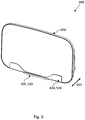
- Fig. 6 shows a PED holder 600 together with a surface abutting the PED according to various embodiments.
- the PED holder 600 may include a clamping structure 420, 520 described above, which includes a clamping flap 424, 524 configured to clamp a PED (not shown) against a surface 650 abutting the PED.
- the surface 650 may be a seat back of the passenger seat, or may be a monitor, or may be a planar support.
- the PED is clamped between the clamping flap 424, 524 and the surface 650.
- the surface 650 may be the back of the passenger seat, and the PED holder 600 is mounted across the back of the passenger seat in a horizontal direction such that the supporting flap of the clamping structure 420, 520 is oriented horizontally and the longitudinal axis of the clamping structure 420, 520 is oriented horizontally and is parallel to the plane of the back of the passenger seat.
- the clamping flap is oriented substantially vertically or inclined inward toward the back of the passenger seat to clamp the PED between the clamping flap and the back of the passenger seat.
- the PED holder 600 may be slidably or tiltably mounted to the back of the passenger seat by a mounting element 410, 510, e.g., shown in Figs 7-10 below.
- the surface 650 may be a planar support or a monitor included in the PED holder 600.
- the entire PED holder 600 is mounted across the back of the passenger seat in a horizontal direction such that the longitudinal axis of the clamping structure 420, 520 is oriented horizontally and is parallel to the plane of the back of the passenger seat.
- the clamping flap is oriented substantially vertically or inclined inward toward the planar support/monitor to clamp the PED between the clamping flap and the planar support/monitor.
- the entire PED holder 600 may be fixedly or tiltably mounted to the back of the passenger seat by a mounting element, e.g., shown in Figs 11-15 below.
- Fig. 7 shows a PED holder 700 together with a surface abutting the PED according to various embodiments.
- the PED holder 700 may include a clamping structure 420 described in various embodiments above, which includes a clamping flap 424 configured to clamp a PED (not shown) against a surface 650 abutting the PED.
- the surface 650 may be a seat back of the passenger seat, or may be a monitor, or may be a planar support.
- the PED is clamped between the clamping flap 424 and the surface 650.
- the mounting element 410 is provided for slidably mounting the clamping structure 420 to the passenger seat.
- the mounting element 410 is configured to slidably mount the clamping structure 420 to the seat back 650 of the passenger seat directly.
- the clamping structure 420 is slidably mounted to the seat back of the passenger seat indirectly through a monitor 650 or a planar support 650.
- the clamping structure 420 may be slidably mounted or coupled to the planar support 650.
- the clamping structure 420 may be slidably mounted or coupled to the monitor 650, in which the PED holder 700 may be referred to as an integrated entertainment system.
- the clamping structure 420 is slidably mounted to the surface 650, such that the clamping structure 420 is moveable or slidable in the translational direction 630 to adjust a space between the clamping flap 424 and the surface 650 abutting the portable electronic device.
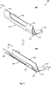
- Fig. 8 shows side views of a slide-in and a slide-out state of the PED holder 700 of Fig. 7 according to various embodiments.
- the clamping flap 424 of the clamping structure 420 is in physical contact or is abutting the surface 650.
- the clamping structure 420 is moved or slide in the translational direction 630 to reach the slide-out state 804, in order to adjust a space between the clamping flap 424 and the surface 650 abutting the portable electronic device.
- the mounting element 410 may include a guide for guiding the translational motion of the clamping structure 420, and may include a stopper for stopping the translational motion of the clamping structure 420.
- the adjustable clamping structure 420 of various embodiments slides in and out of the surface 650(e.g. IFE monitor/planar support/seat back) in the translational motion.
- Guides may be installed within the assembly of the PED holder or at the passenger seat to provide the sliding mechanism, e.g. similar to the sliding mechanism of a drawer.
- the mounting element 410 may include a hinge, and may be configured to tiltably mount the clamping structure to the surface 650.
- a PED holder for a passenger seat, including a planar support, a longitudinal clamping structure attached to the planar support, and a mounting element for slidably mounting the PED holder to the passenger seat.
- the clamping structure has a generally L-shaped cross-section, and is configured to hold the portable electronic device between the clamping structure and the planar support.
- the clamping structure includes a supporting flap forming an L-base of the generally L-shaped clamping structure and configured to support the portable electronic device, and a clamping flap forming an L-leg of the generally L-shaped clamping structure and configured to clamp the portable electronic device against the planar support.
- the portable electronic device holder is configured to be mounted to a back of the passenger seat slidably in a direction at least substantially perpendicular to a plane of the back of the seat to adjust a space between the clamping flap and the planar support.
- the clamping structure is attached to the planar support slidably in a direction at least substantially perpendicular to a plane of the planar support and/or a plane of the back of the seat to adjust a space between the clamping flap and the planar support.
- the clamping structure is tiltable relative to a back of the passenger seat to adjust a viewing angle of the portable electronic device.
- the clamping flap is pivotably coupled to the supporting flap through a hinge. In various embodiments, the clamping flap is pivotable to adjust a space between the clamping flap and the planar support.
- the clamping structure includes a biasing element configured to urge the clamping flap towards the supporting flap.
- the biasing element is configured to exert a force to clamp the portable electronic device against the planar support, when the portable electronic device is held by the portable electronic device holder.
- the mounting element may be integrally formed together with the supporting flap of the clamping structure.
- the mounting element may be connected to the clamping structure, e.g. the mounting element may be separate pieces which is joined or connected to the clamping structure.
- a further mounting element may be provided for tiltably mounting the planar support to the passenger seat.
- the clamping flap is made of transparent material.
- an integrated entertainment system for a passenger seat, including a monitor mounted to a back of the passenger seat, a longitudinal clamping structure mounted to the monitor, and a mounting element for slidably mounting the clamping structure to the monitor.
- the clamping structure has a generally L-shaped cross-section, and is configured to hold the portable electronic device between the clamping structure and the planar support.
- the clamping structure includes a supporting flap forming an L-base of the generally L-shaped clamping structure and configured to support the portable electronic device, and a clamping flap forming an L-leg of the generally L-shaped clamping structure and configured to clamp the portable electronic device against the monitor.
- clamping structure is mounted to the monitor slidably in a direction at least substantially perpendicular to a surface of monitor to adjust a space between the clamping flap and the monitor.
- the clamping flap is pivotably coupled to the supporting flap through a hinge. In various embodiments, the clamping flap is pivotable to adjust a space between the clamping flap and the monitor.
- the clamping structure includes a biasing element configured to urge the clamping flap towards the supporting flap, thereby exerting a force to clamp the portable electronic device against the monitor when the portable electronic device is held by the integrated entertainment system.
- the mounting element may be integrally formed together with the supporting flap of the clamping structure.
- the mounting element may be connected to the clamping structure, e.g. the mounting element may be separate pieces which is joined or connected to the clamping structure.
- a further mounting element may be provided for tiltably mounting the monitor to the passenger seat.
- the clamping flap is made of transparent material.
- Fig. 9 shows perspective views of a closed state and an open state of a PED holder according to various embodiments
- Fig. 10 shows side views of the closed state and the open state of the PED holder of Fig. 9 according to various embodiments.
- the PED holder 900 may be the PED holder 600 of Fig. 6 , including a clamping structure 520 and a mounting element 510 of Fig. 5 described in various embodiments above.
- the clamping structure 520 includes the clamping flap 524 configured to clamp a PED (not shown) against the surface 650 abutting the PED.
- the surface 650 may be a seat back of the passenger seat, or may be a monitor, or may be a planar support.
- the PED is clamped between the clamping flap 524 and the surface 650.
- the mounting element 510 is provided for tiltably mounting the clamping structure 520 to the passenger seat.
- the clamping structure 520 is tiltable relative to the passenger seat in a rotational direction to adjust a viewing angle of the portable electronic device.
- the mounting element 510 is configured to tiltably mount the clamping structure 520 to the seat back 650 of the passenger seat directly.
- the mounting element 510 may include two pieces as shown in Fig. 9 , which may be respectively installed at the two opposing sides of the passenger seat, or may be installed at the seat back of the passenger seat.
- the clamping structure 520 is tiltably mounted to the seat back of the passenger seat through a monitor 650 or a planar support 650 as described in more detail below. It is understood that the mounting element 510 may be an integral piece, or may include a plurality of separated mounting pieces.
- the clamping structure 520 may further be slidably mounted or coupled to the planar support 650, such that the clamping structure 520 may be slidable relative to the planar support as in Fig. 8 .
- the clamping structure 520 may be slidably mounted or coupled to the monitor 650 such that the clamping structure 520 may be slidable relative to the monitor as in Fig. 8
- the PED holder 900 may be referred to as an integrated entertainment system.
- the surface 650 abutting the portable electronic device may be the seat back of the passenger seat, for example, when the PED holder 900 is directly mounted to the seat back of the passenger seat.
- the surface 650 abutting the portable electronic device may be a monitor or a planar support mounted to the passenger seat.
- the PED holder 900 may be provided to include the clamping structure 520, the mounting element 510, and a planar support/monitor 650 integrated together, such that the entire PED holder may be installed to the passenger seat, or to other objects, such as wall, desk, etc.
- the mounting element 510 may be integrally formed together with the supporting flap 522 of the clamping structure 520. In other embodiments, the mounting element 510 may be connected to the clamping structure, e.g. the mounting element may be separate pieces which is joined or connected to the clamping structure 520.
- the clamping flap 524 is pivotably coupled to the supporting flap 522 through a hinge 526. In various embodiments, the clamping flap 524 may be pivotable to adjust a space between the clamping flap 524 and the surface 650 abutting the portable electronic device.
- the clamping structure 520 includes a biasing element, e.g. a spring, configured to urge the clamping flap 524 towards the supporting flap 522, thereby exerting a force to clamp the portable electronic device against the surface abutting the portable electronic device.
- a biasing element e.g. a spring
- the clamping flap 524 in the closed states 902, 1002, the clamping flap 524 is urged towards the supporting flap 522 and is abutting the surface 650.
- the camping flap 524 is pivoted along the hinge 526 in the rotational direction 960, thereby to open the space between the clamping flap 524 and the surface 650. In this manner, the space between the clamping flap 524 and the surface 650 for clamping PEDs can be adjusted to cater for PEDs of different widths.
- the PED holder is pivotable or rotatable about a hinge as shown in Fig. 9 and Fig. 10 .
- the passenger may pull the clamping flap 524 to open the clamping structure 520, so as to open up a space that a PED can be fitted in between the clamping structure 520 and the surface 650.
- the clamping structure 520 is movable in translational motion, or rotational motion, or both translational and rotational motion, and is provided to cater for PEDs of different thickness and/or to adjust the viewing angle of PEDs.
- the clamping flap 524 may be formed as a single flap, or may be formed by a plurality of portions connected by interconnecting portions, or may be formed by a plurality of portions separated from each other.
- the clamping flap 524 may be made of transparent material, to prevent or minimize blockage of the effective area (e.g. the screen) of the PED.
- the entire clamping structure 520 may be made of transparent material.
- Fig. 11 shows a PED holder 1100 according to various embodiments.
- the PED holder 1100 may include a clamping structure 420 described in various embodiments above, and a planar support 650.
- the clamping structure 420 includes a clamping flap configured to clamp a PED (not shown) against the planar support 650 abutting the PED.
- the planar support 650 may be a monitor, and the PED holder 1100 including the monitor is referred to as an integrated entertainment system.
- the clamping structure 420 is slidably mounted to the surface 650, such that the clamping structure 420 is moveable or slidable in the translational direction to adjust a space between the clamping flap of the clamping structure 420 and the surface 650 abutting the portable electronic device, similar to the embodiments of Fig. 7 .
- a mounting element 1110 is provided for mounting the planar support/monitor 650 to the passenger seat.
- the angle between the passenger seat and the planar support/monitor 650 may be fixed, e.g. to align the planar support/monitor 650 substantially parallel to the plane of the back of the passenger seat.
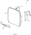
- Fig. 12 shows a PED holder according to various embodiments
- Fig. 13 shows an exploded view of the PED holder of Fig. 12 according to various embodiments.
- the PED holder 1100 of Fig. 12 and Fig. 13 may be the PED holder described in Fig. 11 above.
- the mounting element 1110 may include a hinge, such that the mounting element 1110 is configured to tiltably mount the planar support/monitor 650 to the passenger seat.
- the planar support/monitor 650 is tiltable relative to the passenger seat in a rotational direction to adjust a viewing angle of the portable electronic device clamped between the planar support/monitor 650 and the clamping structure 420.
- the mounting element 1110 may include two pieces as shown in Figs. 11-13 , which may be respectively located at the two opposing corners or side edges of the planar support/monitor 650 for mounting to the passenger seat.
- the mounting element 1110 may be a single piece, for example, located at the top edge of the planar support/monitor 650.
- the mounting element 1110 may include a plurality of pieces.
- Fig. 14 shows a PED holder according to various embodiments
- Fig. 15 shows an exploded view of the PED holder of Fig. 14 according to various embodiments.
- the PED holder 1400 is similar to the PED holder of Fig. 9 , including a clamping structure 520 and a mounting element 1410 similar to the mounting element 510 of Fig. 5 described in various embodiments above.
- the clamping structure 520 includes the clamping flap 524 configured to clamp a PED (not shown) against a planar support/monitor 650 abutting the PED.
- planar support/monitor 650 may be mounted on the supporting flap 522 of the clamping structure 520.
- the PED holder 1400 including the monitor 650 is referred to as an integrated entertainment system.
- the PED holder 1400 may be provided to include the clamping structure 520, the mounting element 1410, and the planar support/monitor 650 integrated together, such that the entire PED holder/integrated entertainment system may be installed to the passenger seat, or to other objects, such as wall, desk, etc.
- the mounting element 1410 is provided for tiltably mounting the clamping structure 520 to the passenger seat.
- the clamping structure 520 is tiltable relative to the passenger seat in a rotational direction to adjust a viewing angle of the portable electronic device.
- the mounting element 1410 is configured to tiltably mount the clamping structure 520 to the seat back of the passenger seat directly.
- the mounting element 1410 may include two pieces as shown in Fig. 14 and Fig. 15 , which may be respectively installed at the two opposing sides of the passenger seat, or may be installed at the seat back of the passenger seat. It is understood that the mounting element 1410 may be an integral piece, or may include a plurality of separated mounting pieces.
- the mounting element 1410 may be integrally formed together with the supporting flap 522 of the clamping structure 520. In other embodiments, the mounting element 1410 may be connected to the clamping structure 520.
- the clamping flap 524 is pivotably coupled to the supporting flap 522 through the hinge 526. In various embodiments, the clamping flap 524 may be pivotable to adjust a space between the clamping flap 524 and the planar support/monitor 650 abutting the portable electronic device.
- the clamping structure 520 includes a biasing element, e.g. a spring, configured to urge the clamping flap 524 towards the supporting flap 522, thereby exerting a force to clamp the portable electronic device against the planar support/monitor 650 abutting the portable electronic device when the PED is held.
- a biasing element e.g. a spring
- a PED holder e.g., the PED holder 1100 of Figs. 11-13 or the PED holder 1400 of Figs. 14-15 , for a passenger seat, including a planar support, a longitudinal clamping structure attached to the planar support, and a mounting element for tiltably mounting the PED holder to the passenger seat.
- the clamping structure has a generally L-shaped cross-section, and is configured to hold the portable electronic device between the clamping structure and the planar support.
- the clamping structure includes a supporting flap forming an L-base of the generally L-shaped clamping structure and configured to support the portable electronic device, and a clamping flap forming an L-leg of the generally L-shaped clamping structure and configured to clamp the portable electronic device against the planar support.
- the portable electronic device holder is configured to be mounted to a back of the passenger seat slidably in a direction at least substantially perpendicular to a plane of the back of the seat to adjust a space between the clamping flap and the planar support.
- the clamping structure is attached to the planar support slidably in a direction at least substantially perpendicular to a plane of the planar support and/or a plane of the back of the seat to adjust a space between the clamping flap and the planar support.
- the clamping structure is tiltable relative to a back of the passenger seat to adjust a viewing angle of the portable electronic device.
- the clamping flap is pivotably coupled to the supporting flap through a hinge. In various embodiments, the clamping flap is pivotable to adjust a space between the clamping flap and the planar support.
- the clamping structure includes a biasing element configured to urge the clamping flap towards the supporting flap, thereby exerting a force to clamp the portable electronic device against the planar support when the PED is held.
- the mounting element may be integrally formed together with the supporting flap of the clamping structure.
- the mounting element may be connected to the clamping structure, e.g. the mounting element may be separate pieces which is joined or connected to the clamping structure.
- the portable electronic device holder may include a further mounting element for tiltably mounting the planar support to the passenger seat.
- the clamping flap is made of transparent material.
- an integrated entertainment system e.g. the integrated entertainment system 1100 of Figs. 11-13 or the integrated entertainment system 1400 of Figs. 14-15 , for a passenger seat, including a monitor mounted to a back of the passenger seat, a longitudinal clamping structure, and a mounting element for slidably or tiltably mounting the clamping structure to the monitor.
- the clamping structure has a generally L-shaped cross-section, and is configured to hold the portable electronic device between the clamping structure and the planar support.
- the clamping structure includes a supporting flap forming an L-base of the generally L-shaped clamping structure and configured to support the portable electronic device, and a clamping flap forming an L-leg of the generally L-shaped clamping structure and configured to clamp the portable electronic device against the planar support.
- the clamping structure is mounted to the monitor slidably in a direction at least substantially perpendicular to a surface of monitor to adjust a space between the clamping flap and the monitor.
- the clamping flap is pivotably coupled to the supporting flap through a hinge. In various embodiments, the clamping flap is pivotable to adjust a space between the clamping flap and the monitor.
- the clamping structure includes a biasing element configured to urge the clamping flap towards the supporting flap, thereby exerting a force to clamp the portable electronic device against the monitor.
- the mounting element may be integrally formed together with the supporting flap of the clamping structure.
- the mounting element may be connected to the clamping structure, e.g. the mounting element may be separate pieces which is joined or connected to the clamping structure.
- the integrated entertainment system may include a further mounting element for tiltably mounting the monitor to the passenger seat.
- the clamping flap is made of transparent material.
- a PED holder/integrated entertainment system slidable in the translation direction perpendicular to the back of the passenger seat to adjust the space between the clamping flap and the surface abutting the PED
- a PED holder/integrated entertainment system having a clamping structure with one flap pivotable coupled to the another flap to adjust the space between the clamping flap and the surface abutting the PED
- a PED holder/integrated entertainment system both slidable in the translation direction and pivotable to adjust the space between the clamping flap and the surface abutting the PED
- a PED holder/integrated entertainment system tiltably mounted to a passenger seat to adjust the viewing angle of the PED and a combination thereof.
- Various embodiments further provide a passenger seat including a portable electronic device holder described in various embodiments of Figs. 4-15 above mounted on the back of the seat.
- Various embodiments further provide a passenger seat including an integrated entertainment system described in various embodiments of Figs. 6-15 above mounted on the back of the seat.
- the IFE system manufacturers' strengths are synergized with the growing trend of PED usage on board the plane.
- Airlines enable their passengers to use their PEDs independently from the tray table.
- airlines do not have to worry about their pouches from being taken away.
- the PED holder takes up less space as shown in Fig. 4-15 above.
- the tiltable PED holder allows the passenger to adjust the PED holder's viewing angle in order to compensate the change in viewing angle when the backrest in front of the passenger changes it recline angle.
- the PED holder may be placed at the upper section of the seatback, which will allow passengers to look at their PED comfortably without staining their necks. This may be achieved by utilizing the IFE mounting provisions for the planar support of the PED holder.
- the planar support of the PED holder may also be the IFE monitor.
- the PED holder of various embodiments neither interferes with passenger's use of the dining table nor is it easily carried away.
- the PED holder is adjustable in translational and/or rotational directions to cater for PEDs of different thickness.
- the PED will be sandwiched between the clamping structure and the planar support/IFE monitor screen/seat back to keep the PED in place.
- the clamping structure can be designed with different grip force to suit for different seat recline and targeted PEDs.
- a PED holder mountable onto an aircraft seat The PED holder may be tiltably mounted, allowing the aircraft passenger to view the PED at different angles.
- Various embodiments provide an integrated entertainment system combining an IFE monitor with a PED holder.
- the PED holder may include a base (e.g. a planar support or a monitor), an adjustable clamping structure, and a mounting provision.
- the base may act as a foundation support for the PED to rest on, which may be an IFE monitor or a planar support, or the seat back of the passenger seat.
- the adjustable clamping structure to grip the PED in place may be moved translational or rotationally, or both.
- the adjustable clamping structure may have a spring force that will automatically try to close the gap between the adjustable clamping structure and the base.
- the mounting provision may be a tiltable mounting provision used to tilt the PED holder, so that the user of the PED holder is able to adjust the viewing angle of the PED.
- the PED is sandwiched between the base and the adjustable clamping structure.
- the adjustable clamping structure may be designed with different shape and size to suit for seat recline and targeted PED requirements.
- the strength of the adjustable clamping structure may also be adjusted to cater for different PEDs.
- the adjustable clamping structure may be made from transparent material to minimize blockage of PED effective area.
Landscapes
- Engineering & Computer Science (AREA)
- Aviation & Aerospace Engineering (AREA)
- Transportation (AREA)
- Mechanical Engineering (AREA)
- Fittings On The Vehicle Exterior For Carrying Loads, And Devices For Holding Or Mounting Articles (AREA)
- Telephone Set Structure (AREA)
- Pivots And Pivotal Connections (AREA)
- Seats For Vehicles (AREA)
- Devices For Indicating Variable Information By Combining Individual Elements (AREA)
- Chair Legs, Seat Parts, And Backrests (AREA)
Claims (12)
- Halter für tragbare elektronische Geräte für einen Passagiersitz, aufweisend:eine längliche Klemmstruktur (520) mit einem allgemein L-förmigen Querschnitt, aufweisend:eine Stützklappe (522), die eine L-Basis der allgemein L-förmigen Klemmstruktur bildet und konfiguriert ist, um ein tragbares elektronisches Gerät zu tragen;eine Klemmklappe (524), die ein L-Bein der allgemein L-förmigen Klemmstruktur bildet und konfiguriert ist, um das tragbare elektronische Gerät gegen eine Oberfläche (650) zu klemmen, die an dem tragbaren elektronischen Gerät anliegt, wobei die Klemmklappe schwenkbar mit der Stützklappe durch ein Scharnier gekoppelt ist, wobei die Klemmstruktur ein Vorspannelement umfasst, das konfiguriert ist, um die Klemmklappe in Richtung der Stützklappe zu drücken, undein Befestigungselement (510) zum verschiebbaren oder kippbaren Befestigen der Klemmstruktur am Passagiersitz.
- Der Halter für tragbare elektronische Geräte gemäß Anspruch 1,
wobei die Klemmstruktur (520) so konfiguriert ist, dass sie auf einer Rückseite des Passagiersitzes verschiebbar in einer Richtung montiert ist, die mindestens im Wesentlichen senkrecht zu einer Ebene der Rückenlehne des Sitzes ist, um einen Raum zwischen der Klemmklappe (521) und der Oberfläche (650) einzustellen, die an das tragbare elektronische Gerät angrenzt. - Der Halter für tragbare elektronische Geräte gemäß Anspruch 1,
wobei die Klemmstruktur (520) kippbar ist, um einen Betrachtungswinkel des tragbaren elektronischen Geräts einzustellen. - Der Halter für tragbare elektronische Geräte gemäß irgend einem der Ansprüche 1 bis 3,
wobei das Befestigungselement (510) integral mit der Stützklappe der Klemmstruktur ausgebildet ist. - Der Halter für tragbare elektronische Geräte gemäß irgend einem der Ansprüche 1 bis 4,
wobei das Befestigungselement (510) mit der Klemmstruktur verbunden ist. - Der Halter für tragbare elektronische Geräte gemäß irgend einem der Ansprüche 1 bis 5,
wobei die Klemmklappe (524) aus einem transparentem Material besteht. - Der Halter für tragbare elektronische Geräte gemäß irgend einem der Ansprüche 1 bis 6,
wobei die Oberfläche (650), die an dem tragbaren elektronischen Gerät anliegt, einen Monitor oder eine planare Stütze umfasst. - Der Halter für tragbare elektronische Geräte gemäß dem Anspruch 1, 3, 4, 5 oder 6, aufweisend:einen planaren Träger, umfassend die Oberfläche (650), die an dem tragbaren elektronischen Gerät anliegt;wobei die längliche Klemmstruktur an dem planaren Träger angebracht ist und konfiguriert ist, um das tragbare elektronische Gerät zwischen der Klemmstruktur (520) und dem planaren Träger zu halten.
- Der Halter für tragbare elektronische Geräte gemäß Anspruch 8,
wobei der Halter für tragbare elektronische Geräte konfiguriert ist, um an einer Rückseite des Passagiersitzes verschiebbar in einer Richtung montiert zu sein, die mindestens im Wesentlichen senkrecht zu einer Ebene der Rückenlehne des Sitzes ist, um einen Raum zwischen der Klemmklappe (524) und dem planaren Träger einzustellen. - Der Halter für tragbare elektronische Geräte gemäß Anspruch 8 oder 9,
wobei die Klemmstruktur (520) in einer Richtung mindestens im Wesentlichen senkrecht zu einer Ebene des planaren Trägers verschiebbar an dem planaren Träger angebracht ist, um einen Raum zwischen der Klemmklappe (524) und dem planaren Träger einzustellen. - Der Halter für tragbare elektronische Geräte gemäß irgend einem der Ansprüche 8 bis 10, aufweisend:
ein weiteres Befestigungselement (510) zum kippbaren Befestigen des planaren Trägers am Passagiersitz. - Der Halter für tragbare elektronische Geräte gemäß dem Anspruch 1, 2, 4, 5 oder 6, und einen Monitor zum Anbringen an einer Rückseite eines Passagiersitzes, wobei der Monitor die Oberfläche (650) aufweist, die zum Anliegen an dem tragbaren elektronischen Gerät geeignet ist;
wobei die längliche Klemmstruktur (520) an dem Monitor angebracht ist und konfiguriert ist, um das tragbare elektronische Gerät zwischen der Klemmstruktur (520) und dem Monitor zu halten,
und das Befestigungselement (510) ist konfiguriert, um die Klemmstruktur verschiebbar oder kippbar an dem Monitor zu montieren.
Applications Claiming Priority (1)
| Application Number | Priority Date | Filing Date | Title |
|---|---|---|---|
| PCT/SG2015/050069 WO2016167720A1 (en) | 2015-04-13 | 2015-04-13 | Portable electronic device holder |
Publications (2)
| Publication Number | Publication Date |
|---|---|
| EP3283370A1 EP3283370A1 (de) | 2018-02-21 |
| EP3283370B1 true EP3283370B1 (de) | 2020-04-22 |
Family
ID=53039557
Family Applications (1)
| Application Number | Title | Priority Date | Filing Date |
|---|---|---|---|
| EP15719869.8A Active EP3283370B1 (de) | 2015-04-13 | 2015-04-13 | Halter für portable elektronische geräte |
Country Status (6)
| Country | Link |
|---|---|
| US (1) | US10597159B2 (de) |
| EP (1) | EP3283370B1 (de) |
| JP (1) | JP6483853B2 (de) |
| CN (1) | CN107709159B (de) |
| SG (1) | SG11201707083UA (de) |
| WO (1) | WO2016167720A1 (de) |
Families Citing this family (6)
| Publication number | Priority date | Publication date | Assignee | Title |
|---|---|---|---|---|
| CA3007549A1 (en) | 2018-06-07 | 2019-12-07 | Michael Furshman | An apparatus for holding a portable electronic device |
| US11050453B2 (en) * | 2019-04-25 | 2021-06-29 | Aatc, Llc | Smart phone holder |
| USD908709S1 (en) | 2019-09-10 | 2021-01-26 | Seth Fine | Holder for a portable electronic device |
| US10906574B1 (en) | 2019-12-30 | 2021-02-02 | Brandy Neal | Phone caddy stroller clamp apparatus |
| US11979048B2 (en) | 2020-09-18 | 2024-05-07 | B/E Aerospace, Inc. | Inductive charging device holder |
| US11076033B1 (en) | 2020-09-29 | 2021-07-27 | Ricardo Huelga | Smart device support |
Citations (1)
| Publication number | Priority date | Publication date | Assignee | Title |
|---|---|---|---|---|
| WO2016092509A1 (en) * | 2014-12-10 | 2016-06-16 | Zodiac Seats France | Retractable device holder for an aircraft seat |
Family Cites Families (17)
| Publication number | Priority date | Publication date | Assignee | Title |
|---|---|---|---|---|
| US2835072A (en) * | 1957-04-30 | 1958-05-20 | Gramacy William | Book support with independent cover holder |
| US5765799A (en) * | 1996-12-10 | 1998-06-16 | Weber; Barbara | Portable collapsible stand for facilitating holding book pages open |
| EP1777111B1 (de) * | 2005-10-20 | 2009-04-29 | Robert Bosch Gmbh | Multifuntionelle Befestigungsvorrichtung für eine elektrische Gerät |
| US8567740B2 (en) * | 2006-03-23 | 2013-10-29 | Byron Richard Tarnutzer | Deployable support unit for reading material |
| EP2046605A1 (de) | 2006-07-25 | 2009-04-15 | Panasonic Avionics Corporation | System und verfahren zur montage von benutzerschnittstellenvorrichtungen |
| US20090189039A1 (en) | 2008-01-29 | 2009-07-30 | Labuda Darrin | Portable Electronic Holder |
| CN201638916U (zh) * | 2009-09-24 | 2010-11-17 | 陈桂宏 | 手机充电架 |
| EP2569187B1 (de) * | 2010-05-14 | 2017-01-25 | Zodiac Seats US LLC | Kupplungseinheit |
| CA2812871C (en) | 2010-10-29 | 2014-09-09 | Christopher Partridge | Portable electronic device holder |
| US8839501B2 (en) | 2011-03-26 | 2014-09-23 | Bryan Ulrich McClain | Seatback-mountable holder for a portable electronic device |
| JP5643463B2 (ja) | 2011-04-04 | 2014-12-17 | ビーイー・エアロスペース・インコーポレーテッド | タブレットコンピュータ用シートバックホルダ |
| DE102012112942A1 (de) | 2012-12-21 | 2014-06-26 | Recaro Aircraft Seating Gmbh & Co. Kg | Flugzeugsitzbefestigungsvorrichtung |
| TR201910601T4 (tr) * | 2012-12-21 | 2019-08-21 | Recaro Aircraft Seating Gmbh & Co Kg | Uçak koltuğu tutma tertibatı. |
| EP3022090B1 (de) * | 2013-07-19 | 2018-05-02 | Zodiac Seats US LLC | Anpassbare unterstützungsvorrichtung für tragbare elektronische vorrichtungen |
| CN203377934U (zh) * | 2013-08-13 | 2014-01-01 | 江西理工大学南昌校区 | 一种便携式新型手机支架 |
| DE102014212635A1 (de) * | 2014-06-30 | 2015-12-31 | Airbus Operations Gmbh | Fahrzeugsitz mit integrierter Halterung für elektronische Geräte |
| US9776722B2 (en) * | 2015-03-24 | 2017-10-03 | B/E Aerospace, Inc. | Seat back personal electronic device holder |
-
2015
- 2015-04-13 JP JP2017553425A patent/JP6483853B2/ja active Active
- 2015-04-13 SG SG11201707083UA patent/SG11201707083UA/en unknown
- 2015-04-13 EP EP15719869.8A patent/EP3283370B1/de active Active
- 2015-04-13 WO PCT/SG2015/050069 patent/WO2016167720A1/en active Application Filing
- 2015-04-13 US US15/561,942 patent/US10597159B2/en active Active
- 2015-04-13 CN CN201580078725.5A patent/CN107709159B/zh active Active
Patent Citations (1)
| Publication number | Priority date | Publication date | Assignee | Title |
|---|---|---|---|---|
| WO2016092509A1 (en) * | 2014-12-10 | 2016-06-16 | Zodiac Seats France | Retractable device holder for an aircraft seat |
Also Published As
| Publication number | Publication date |
|---|---|
| EP3283370A1 (de) | 2018-02-21 |
| US10597159B2 (en) | 2020-03-24 |
| SG11201707083UA (en) | 2017-09-28 |
| JP6483853B2 (ja) | 2019-03-13 |
| WO2016167720A1 (en) | 2016-10-20 |
| CN107709159A (zh) | 2018-02-16 |
| US20180111690A1 (en) | 2018-04-26 |
| WO2016167720A9 (en) | 2017-08-17 |
| JP2018513806A (ja) | 2018-05-31 |
| CN107709159B (zh) | 2021-03-02 |
Similar Documents
| Publication | Publication Date | Title |
|---|---|---|
| EP3283370B1 (de) | Halter für portable elektronische geräte | |
| EP3450318B1 (de) | Ausfahrbare tischanordnung | |
| EP3303133B1 (de) | Entfaltbare rückenlehnenhalterung für tragbare elektronische vorrichtungen | |
| US8851565B2 (en) | Seatback holder for tablet computers | |
| US9820568B2 (en) | Integral tray table personal electronic device holder and tray table | |
| US10703482B1 (en) | Deployable portable electronic device holder for aircraft seat | |
| EP3350022B1 (de) | Tischhalter für tragbares elektronisches gerät | |
| EP3230162A1 (de) | Einziehbarer vorrichtungshalter für einen flugzeugsitz | |
| EP3722209B1 (de) | Passagierunterhaltungsvorrichtung, passagiersitzanordnung und fahrzeug | |
| US20220234739A1 (en) | Portable electronic device holder for seat | |
| US20220289118A1 (en) | Deployable personal entertainment device holder | |
| US20220371526A1 (en) | Adjustable device holder | |
| US10689116B1 (en) | Seat system with mounting option | |
| US11858427B2 (en) | PED holder arm concept | |
| WO2018151664A1 (en) | Portable electronic device holder for a passenger seat |
Legal Events
| Date | Code | Title | Description |
|---|---|---|---|
| STAA | Information on the status of an ep patent application or granted ep patent |
Free format text: STATUS: THE INTERNATIONAL PUBLICATION HAS BEEN MADE |
|
| PUAI | Public reference made under article 153(3) epc to a published international application that has entered the european phase |
Free format text: ORIGINAL CODE: 0009012 |
|
| STAA | Information on the status of an ep patent application or granted ep patent |
Free format text: STATUS: REQUEST FOR EXAMINATION WAS MADE |
|
| 17P | Request for examination filed |
Effective date: 20170905 |
|
| AK | Designated contracting states |
Kind code of ref document: A1 Designated state(s): AL AT BE BG CH CY CZ DE DK EE ES FI FR GB GR HR HU IE IS IT LI LT LU LV MC MK MT NL NO PL PT RO RS SE SI SK SM TR |
|
| AX | Request for extension of the european patent |
Extension state: BA ME |
|
| DAV | Request for validation of the european patent (deleted) | ||
| DAX | Request for extension of the european patent (deleted) | ||
| RAP1 | Party data changed (applicant data changed or rights of an application transferred) |
Owner name: ST ENGINEERING AEROSPACE LTD. |
|
| STAA | Information on the status of an ep patent application or granted ep patent |
Free format text: STATUS: EXAMINATION IS IN PROGRESS |
|
| 17Q | First examination report despatched |
Effective date: 20190301 |
|
| GRAP | Despatch of communication of intention to grant a patent |
Free format text: ORIGINAL CODE: EPIDOSNIGR1 |
|
| STAA | Information on the status of an ep patent application or granted ep patent |
Free format text: STATUS: GRANT OF PATENT IS INTENDED |
|
| INTG | Intention to grant announced |
Effective date: 20191128 |
|
| GRAS | Grant fee paid |
Free format text: ORIGINAL CODE: EPIDOSNIGR3 |
|
| GRAA | (expected) grant |
Free format text: ORIGINAL CODE: 0009210 |
|
| STAA | Information on the status of an ep patent application or granted ep patent |
Free format text: STATUS: THE PATENT HAS BEEN GRANTED |
|
| AK | Designated contracting states |
Kind code of ref document: B1 Designated state(s): AL AT BE BG CH CY CZ DE DK EE ES FI FR GB GR HR HU IE IS IT LI LT LU LV MC MK MT NL NO PL PT RO RS SE SI SK SM TR |
|
| REG | Reference to a national code |
Ref country code: CH Ref legal event code: EP |
|
| REG | Reference to a national code |
Ref country code: IE Ref legal event code: FG4D |
|
| REG | Reference to a national code |
Ref country code: DE Ref legal event code: R096 Ref document number: 602015051122 Country of ref document: DE |
|
| REG | Reference to a national code |
Ref country code: AT Ref legal event code: REF Ref document number: 1259752 Country of ref document: AT Kind code of ref document: T Effective date: 20200515 |
|
| REG | Reference to a national code |
Ref country code: LT Ref legal event code: MG4D |
|
| REG | Reference to a national code |
Ref country code: NL Ref legal event code: MP Effective date: 20200422 |
|
| PG25 | Lapsed in a contracting state [announced via postgrant information from national office to epo] |
Ref country code: GR Free format text: LAPSE BECAUSE OF FAILURE TO SUBMIT A TRANSLATION OF THE DESCRIPTION OR TO PAY THE FEE WITHIN THE PRESCRIBED TIME-LIMIT Effective date: 20200723 Ref country code: PT Free format text: LAPSE BECAUSE OF FAILURE TO SUBMIT A TRANSLATION OF THE DESCRIPTION OR TO PAY THE FEE WITHIN THE PRESCRIBED TIME-LIMIT Effective date: 20200824 Ref country code: NO Free format text: LAPSE BECAUSE OF FAILURE TO SUBMIT A TRANSLATION OF THE DESCRIPTION OR TO PAY THE FEE WITHIN THE PRESCRIBED TIME-LIMIT Effective date: 20200722 Ref country code: SE Free format text: LAPSE BECAUSE OF FAILURE TO SUBMIT A TRANSLATION OF THE DESCRIPTION OR TO PAY THE FEE WITHIN THE PRESCRIBED TIME-LIMIT Effective date: 20200422 Ref country code: IS Free format text: LAPSE BECAUSE OF FAILURE TO SUBMIT A TRANSLATION OF THE DESCRIPTION OR TO PAY THE FEE WITHIN THE PRESCRIBED TIME-LIMIT Effective date: 20200822 Ref country code: FI Free format text: LAPSE BECAUSE OF FAILURE TO SUBMIT A TRANSLATION OF THE DESCRIPTION OR TO PAY THE FEE WITHIN THE PRESCRIBED TIME-LIMIT Effective date: 20200422 Ref country code: NL Free format text: LAPSE BECAUSE OF FAILURE TO SUBMIT A TRANSLATION OF THE DESCRIPTION OR TO PAY THE FEE WITHIN THE PRESCRIBED TIME-LIMIT Effective date: 20200422 Ref country code: LT Free format text: LAPSE BECAUSE OF FAILURE TO SUBMIT A TRANSLATION OF THE DESCRIPTION OR TO PAY THE FEE WITHIN THE PRESCRIBED TIME-LIMIT Effective date: 20200422 |
|
| REG | Reference to a national code |
Ref country code: AT Ref legal event code: MK05 Ref document number: 1259752 Country of ref document: AT Kind code of ref document: T Effective date: 20200422 |
|
| PG25 | Lapsed in a contracting state [announced via postgrant information from national office to epo] |
Ref country code: HR Free format text: LAPSE BECAUSE OF FAILURE TO SUBMIT A TRANSLATION OF THE DESCRIPTION OR TO PAY THE FEE WITHIN THE PRESCRIBED TIME-LIMIT Effective date: 20200422 Ref country code: LV Free format text: LAPSE BECAUSE OF FAILURE TO SUBMIT A TRANSLATION OF THE DESCRIPTION OR TO PAY THE FEE WITHIN THE PRESCRIBED TIME-LIMIT Effective date: 20200422 Ref country code: BG Free format text: LAPSE BECAUSE OF FAILURE TO SUBMIT A TRANSLATION OF THE DESCRIPTION OR TO PAY THE FEE WITHIN THE PRESCRIBED TIME-LIMIT Effective date: 20200722 Ref country code: RS Free format text: LAPSE BECAUSE OF FAILURE TO SUBMIT A TRANSLATION OF THE DESCRIPTION OR TO PAY THE FEE WITHIN THE PRESCRIBED TIME-LIMIT Effective date: 20200422 |
|
| PG25 | Lapsed in a contracting state [announced via postgrant information from national office to epo] |
Ref country code: AL Free format text: LAPSE BECAUSE OF FAILURE TO SUBMIT A TRANSLATION OF THE DESCRIPTION OR TO PAY THE FEE WITHIN THE PRESCRIBED TIME-LIMIT Effective date: 20200422 |
|
| REG | Reference to a national code |
Ref country code: DE Ref legal event code: R097 Ref document number: 602015051122 Country of ref document: DE |
|
| PG25 | Lapsed in a contracting state [announced via postgrant information from national office to epo] |
Ref country code: ES Free format text: LAPSE BECAUSE OF FAILURE TO SUBMIT A TRANSLATION OF THE DESCRIPTION OR TO PAY THE FEE WITHIN THE PRESCRIBED TIME-LIMIT Effective date: 20200422 Ref country code: AT Free format text: LAPSE BECAUSE OF FAILURE TO SUBMIT A TRANSLATION OF THE DESCRIPTION OR TO PAY THE FEE WITHIN THE PRESCRIBED TIME-LIMIT Effective date: 20200422 Ref country code: DK Free format text: LAPSE BECAUSE OF FAILURE TO SUBMIT A TRANSLATION OF THE DESCRIPTION OR TO PAY THE FEE WITHIN THE PRESCRIBED TIME-LIMIT Effective date: 20200422 Ref country code: EE Free format text: LAPSE BECAUSE OF FAILURE TO SUBMIT A TRANSLATION OF THE DESCRIPTION OR TO PAY THE FEE WITHIN THE PRESCRIBED TIME-LIMIT Effective date: 20200422 Ref country code: IT Free format text: LAPSE BECAUSE OF FAILURE TO SUBMIT A TRANSLATION OF THE DESCRIPTION OR TO PAY THE FEE WITHIN THE PRESCRIBED TIME-LIMIT Effective date: 20200422 Ref country code: SM Free format text: LAPSE BECAUSE OF FAILURE TO SUBMIT A TRANSLATION OF THE DESCRIPTION OR TO PAY THE FEE WITHIN THE PRESCRIBED TIME-LIMIT Effective date: 20200422 Ref country code: RO Free format text: LAPSE BECAUSE OF FAILURE TO SUBMIT A TRANSLATION OF THE DESCRIPTION OR TO PAY THE FEE WITHIN THE PRESCRIBED TIME-LIMIT Effective date: 20200422 Ref country code: CZ Free format text: LAPSE BECAUSE OF FAILURE TO SUBMIT A TRANSLATION OF THE DESCRIPTION OR TO PAY THE FEE WITHIN THE PRESCRIBED TIME-LIMIT Effective date: 20200422 |
|
| PG25 | Lapsed in a contracting state [announced via postgrant information from national office to epo] |
Ref country code: SK Free format text: LAPSE BECAUSE OF FAILURE TO SUBMIT A TRANSLATION OF THE DESCRIPTION OR TO PAY THE FEE WITHIN THE PRESCRIBED TIME-LIMIT Effective date: 20200422 Ref country code: PL Free format text: LAPSE BECAUSE OF FAILURE TO SUBMIT A TRANSLATION OF THE DESCRIPTION OR TO PAY THE FEE WITHIN THE PRESCRIBED TIME-LIMIT Effective date: 20200422 |
|
| PLBE | No opposition filed within time limit |
Free format text: ORIGINAL CODE: 0009261 |
|
| STAA | Information on the status of an ep patent application or granted ep patent |
Free format text: STATUS: NO OPPOSITION FILED WITHIN TIME LIMIT |
|
| 26N | No opposition filed |
Effective date: 20210125 |
|
| PG25 | Lapsed in a contracting state [announced via postgrant information from national office to epo] |
Ref country code: SI Free format text: LAPSE BECAUSE OF FAILURE TO SUBMIT A TRANSLATION OF THE DESCRIPTION OR TO PAY THE FEE WITHIN THE PRESCRIBED TIME-LIMIT Effective date: 20200422 |
|
| REG | Reference to a national code |
Ref country code: DE Ref legal event code: R119 Ref document number: 602015051122 Country of ref document: DE |
|
| PG25 | Lapsed in a contracting state [announced via postgrant information from national office to epo] |
Ref country code: MC Free format text: LAPSE BECAUSE OF FAILURE TO SUBMIT A TRANSLATION OF THE DESCRIPTION OR TO PAY THE FEE WITHIN THE PRESCRIBED TIME-LIMIT Effective date: 20200422 |
|
| GBPC | Gb: european patent ceased through non-payment of renewal fee |
Effective date: 20210413 |
|
| PG25 | Lapsed in a contracting state [announced via postgrant information from national office to epo] |
Ref country code: LU Free format text: LAPSE BECAUSE OF NON-PAYMENT OF DUE FEES Effective date: 20210413 |
|
| REG | Reference to a national code |
Ref country code: BE Ref legal event code: MM Effective date: 20210430 |
|
| PG25 | Lapsed in a contracting state [announced via postgrant information from national office to epo] |
Ref country code: LI Free format text: LAPSE BECAUSE OF NON-PAYMENT OF DUE FEES Effective date: 20210430 Ref country code: CH Free format text: LAPSE BECAUSE OF NON-PAYMENT OF DUE FEES Effective date: 20210430 Ref country code: GB Free format text: LAPSE BECAUSE OF NON-PAYMENT OF DUE FEES Effective date: 20210413 Ref country code: FR Free format text: LAPSE BECAUSE OF NON-PAYMENT OF DUE FEES Effective date: 20210430 Ref country code: DE Free format text: LAPSE BECAUSE OF NON-PAYMENT OF DUE FEES Effective date: 20211103 |
|
| PG25 | Lapsed in a contracting state [announced via postgrant information from national office to epo] |
Ref country code: IE Free format text: LAPSE BECAUSE OF NON-PAYMENT OF DUE FEES Effective date: 20210413 |
|
| PG25 | Lapsed in a contracting state [announced via postgrant information from national office to epo] |
Ref country code: BE Free format text: LAPSE BECAUSE OF NON-PAYMENT OF DUE FEES Effective date: 20210430 |
|
| PG25 | Lapsed in a contracting state [announced via postgrant information from national office to epo] |
Ref country code: HU Free format text: LAPSE BECAUSE OF FAILURE TO SUBMIT A TRANSLATION OF THE DESCRIPTION OR TO PAY THE FEE WITHIN THE PRESCRIBED TIME-LIMIT; INVALID AB INITIO Effective date: 20150413 |
|
| PG25 | Lapsed in a contracting state [announced via postgrant information from national office to epo] |
Ref country code: CY Free format text: LAPSE BECAUSE OF FAILURE TO SUBMIT A TRANSLATION OF THE DESCRIPTION OR TO PAY THE FEE WITHIN THE PRESCRIBED TIME-LIMIT Effective date: 20200422 |
|
| PG25 | Lapsed in a contracting state [announced via postgrant information from national office to epo] |
Ref country code: MK Free format text: LAPSE BECAUSE OF FAILURE TO SUBMIT A TRANSLATION OF THE DESCRIPTION OR TO PAY THE FEE WITHIN THE PRESCRIBED TIME-LIMIT Effective date: 20200422 |