EP3283231B1 - Colour change system - Google Patents
Colour change system Download PDFInfo
- Publication number
- EP3283231B1 EP3283231B1 EP16728214.4A EP16728214A EP3283231B1 EP 3283231 B1 EP3283231 B1 EP 3283231B1 EP 16728214 A EP16728214 A EP 16728214A EP 3283231 B1 EP3283231 B1 EP 3283231B1
- Authority
- EP
- European Patent Office
- Prior art keywords
- valve
- media
- stator
- selection head
- control channel
- Prior art date
- Legal status (The legal status is an assumption and is not a legal conclusion. Google has not performed a legal analysis and makes no representation as to the accuracy of the status listed.)
- Active
Links
Images


Classifications
-
- B—PERFORMING OPERATIONS; TRANSPORTING
- B05—SPRAYING OR ATOMISING IN GENERAL; APPLYING FLUENT MATERIALS TO SURFACES, IN GENERAL
- B05B—SPRAYING APPARATUS; ATOMISING APPARATUS; NOZZLES
- B05B15/00—Details of spraying plant or spraying apparatus not otherwise provided for; Accessories
- B05B15/50—Arrangements for cleaning; Arrangements for preventing deposits, drying-out or blockage; Arrangements for detecting improper discharge caused by the presence of foreign matter
- B05B15/55—Arrangements for cleaning; Arrangements for preventing deposits, drying-out or blockage; Arrangements for detecting improper discharge caused by the presence of foreign matter using cleaning fluids
-
- B—PERFORMING OPERATIONS; TRANSPORTING
- B05—SPRAYING OR ATOMISING IN GENERAL; APPLYING FLUENT MATERIALS TO SURFACES, IN GENERAL
- B05B—SPRAYING APPARATUS; ATOMISING APPARATUS; NOZZLES
- B05B12/00—Arrangements for controlling delivery; Arrangements for controlling the spray area
- B05B12/14—Arrangements for controlling delivery; Arrangements for controlling the spray area for supplying a selected one of a plurality of liquids or other fluent materials or several in selected proportions to a spray apparatus, e.g. to a single spray outlet
- B05B12/149—Arrangements for controlling delivery; Arrangements for controlling the spray area for supplying a selected one of a plurality of liquids or other fluent materials or several in selected proportions to a spray apparatus, e.g. to a single spray outlet characterised by colour change manifolds or valves therefor
-
- B—PERFORMING OPERATIONS; TRANSPORTING
- B08—CLEANING
- B08B—CLEANING IN GENERAL; PREVENTION OF FOULING IN GENERAL
- B08B9/00—Cleaning hollow articles by methods or apparatus specially adapted thereto
- B08B9/02—Cleaning pipes or tubes or systems of pipes or tubes
- B08B9/027—Cleaning the internal surfaces; Removal of blockages
Definitions
- the invention relates to a color change system according to the preamble of claim 1.
- a color change system in which fluid pressure-controlled media valves are arranged in a stator, a media inlet arranged in a selection head, which was rotated in front of the media valve outlet of an open media valve, being supplied with a colored medium (lacquer). Furthermore, a flushing line is provided which opens laterally into the media line adjoining the media inlet. Such an arrangement only allows the media line to be flushed when the selection head rests on the stator. Thus, during a flush, the selection head cannot be rotated with respect to the stator and thus there can be no color change.
- the media valve consists of a valve closing body and a valve seat in the stator and a fluid-operated tappet in the selection head. For flushing, this is withdrawn so that the media valve closes. A flush valve is then opened to flush the media line. The selection head rests on the stator to keep the media inlet closed.
- the media valve is actuated by a plunger fixed to the selection head.
- the selection head rests on the stator to keep the media inlet closed when the media line is flushed.
- WO 01/51216 A2 discloses a color change system with a stator having a plurality of color connections, a media valve being located in each color connection.
- a selection head can optionally be coupled to one of the paint connections, a plunger connected to an actuating piston in the selection head pushing open the respective media valve, so that a medium can flow from the selected paint connection into a media line in the selection head.
- a flushing line which is controlled by an externally operated valve, opens into the media line.
- the invention is based on the task of simplifying the control of the media valves and making them safer and of creating a possibility that the media line can be flushed during a color change.
- the invention provides that a check valve is arranged in the media inlet in the immediate connection to the rear of the selection head, which blocks to the back of the selection head and that the flushing line, in which the flushing check valve is located, downstream of the check valve in the media line flows into.
- the invention further provides that the stator has a fluid connection which in each case has a control channel with the control pressure chambers of the media valves is connected to switch them, that in each of these control channels there is a switching valve mechanically actuated by a cam, and that a cam is attached to the rear of the selection head, which, when the rear of the selection head is placed on the front of the stator opens the switching valve belonging to the media valve, the media valve outlet in the stator of which is connected to the media inlet in the selection head.
- Such an actuation can be implemented most simply by the fact that the selection head can be moved perpendicularly to the front of the stator, that the cam is formed on the rear of the selection head and projects vertically from it, that the switching valves are accommodated in the bores opening into the front of the stator, the cam being adapted to immerse in the bores and the bores being oriented to the media valve outlets in the same manner as the cam to the media inlet.
- the invention provides that the media valves are fluid-controlled, that the stator for each media valve has a fluid connection on the front of the stator, which is connected via a control channel to the control pressure chamber of the associated media valve in order to switch it, with a check valve being present in each control channel that blocks towards the fluid connection, and that a collection control channel runs in the selection head, which opens into the rear of the selection head, the opening of the collection control channel being aligned with the fluid connection, the control channel leading to the media valve, the media valve outlet of which is in register with the media inlet.
- a color change can therefore take place relatively quickly. While the selection head is moving to a next position, the media line is flushed in the selection head so that the the next media valve that is fed in does not mix with the remnants in the media line. According to the invention, the conversion time is used for flushing the media line, so that the change between two colors can take place more quickly.
- the invention is therefore based on the task of setting up a color change system with at least one multi-color media valve to which several colors are connected so that it is possible to clean it after a color change and thereby a color change by adjusting the selection head to other media valves not to hinder time.
- the invention provides that at least one of the media valves has a circulation valve in the Stator is assigned, the outlet of which has a connection to the inlet of the media valve, and that the media valve is designed such that when its control pressure chamber is pressurized, the valve closing body of the circulation valve is connected to an actuating piston which can be acted upon by a fluid pressure and which is arranged within the stator is adjacent to a control pressure chamber, the circulation valve being designed such that it is closed when pressure is applied to its control pressure chamber.
- a control pressure is applied to both control pressure chambers, whereby the media valve opens and the circulation valve closes. Paint that is in contact with the media feed of the media valve is fed through the open media valve into the media line.
- the control pressure is taken from the control pressure chambers so that the media valve closes and the circulation valve opens.
- the current paint can first be fed from the media valve back into a container via the switching valve by means of a sliding medium and then the media valve is cleaned by means of a purge air.
- the selection head Since the media outlet of the media valve is closed, the selection head need not be docked. Rather, it can be brought in one position to another media valve so that the paint supplied there can be used.
- This arrangement allows the media valve to be flushed so that it can be used as a multi-color media valve.
- Control pressure chamber of the circulation valve connected to the fluid connection via a switchable additional control channel.
- the additional control channel is switched with the switching valve of the associated media valve. Control channel and additional control channel are thus opened or closed at the same time.
- an additional switching valve that can be mechanically actuated by a cam can be provided in the additional control channel.
- control channel runs over the separating surface between the stator and the selection head.
- the color change system consists of a stator 1 and a selection head 2, the z. B. is designed as a rotor.
- the stator 1 there are a large number of media valves 3, each of which is connected to a media feed 4 and whose media valve outlets 5 are located in the front 6 of the stator 1.
- the media valves 3 are z. B. on a circle, so that by rotating the selection head 2, the media line 7, which opens into a media inlet 8 in the rear 9 of the selection head 2, can be brought to cover with one of the media valve outlets 5.
- a check valve 10 that opens into the media line 7.
- a flush line 11 opens, in which there is a further flush check valve 12 which opens in the direction of the media line 7.
- the media valve 3 is controlled by compressed air (hydraulic control is also possible in principle).
- the valve closing body is connected to an actuating piston which can be acted upon by a fluid pressure and which is arranged within the stator and which adjoins a control pressure chamber.
- the actuating piston is not shown here.
- a suitable version of the media valve with an actuator is in the DE 10 2015 102 332 A1 described: The valve closing body are located within a Stator-formed valve chamber and are displaceable against a valve sealing seat directed into the valve chamber.
- Each media valve 3 is embedded in a cartridge which is fastened in a recess on the back of the stator 1. Inside the cartridge is a hollow valve stem, on the head of which the conical valve closing body is attached. This interacts with the likewise conical valve seat, which is formed in the head of the cartridge.
- the hollow design of the valve stem ensures that the medium is guided in a streamlined manner.
- the back of the stator 1 has a fluid or compressed air connection 16 on a ring line 17, which is connected via a control channel 18 to the actuation of the media valves 3.
- a switching valve 19 which has a dumbbell-shaped closing body 20, one head of the closing body 20 being able to be placed against a sealing ring 21, so that the control channel 18 is closed.
- the closing body 20 is actuated by means of a cam 22 which is located on the rear 9 of the selection head 2 and which plunges into a bore 23 in which the switching valve 19 is located.
- the Fig. 1 shows that the stator 1 and the selection head 2 are placed against one another, that is to say are coupled, so that the cam 22 dips into the bore 23 and the switching valve 19 opens, so that the control channel 18 is released.
- the media valve 3 is still closed, ie its valve closing body 24 is still resting on the valve sealing seat 25.
- the check valve 10 is slightly open, since its valve ball is applied to the valve closing body 24 of the media valve 3.
- the Fig. 2 shows the situation in which compressed air is applied to the compressed air connection 16.
- the media valve 3 opens, as a result of which the valve closing body 24 moves away from the valve sealing seat 25.
- the inflowing paint pushes the valve ball of the check valve 10 in front of it and opens the media inlet 8 further.
- the flush line 11 is blocked by the flush check valve 12.
- a color To change a color, first, as in Fig. 3 shown, the compressed air is switched off again, so that the media valve 3 closes and the check valve 10 also changes into a largely closed position. If a flushing agent is now introduced via the flushing line 11, the flushing check valve 12 opens and the flushing agent flows into the media line 7. An escape via the media inlet 8 is prevented since the latter is sealed off from the outside by means of a sealing ring 26.
- the switching valve 19 is first closed because the cam 22 has withdrawn from the bore 23.
- the check valve 10 closes, so that the media inlet 8 is closed and the flushing can continue during the movement of the selection head 2 to the next media valve 3. This is associated with a considerable saving of time.
- each media valve 3 is connected to its own control channel 31 with its own fluid connection 32 in the front side 6 of the stator 1.
- each fluid connection 32 there is a check valve 33, which closes towards the front 6.
- the selection head 2 there is a single collective control channel 34 which is connected to a fluid source (compressed air connection), not shown here.
- the mouth of the collective control channel 34 is aligned with the fluid connection 32 (compressed air connection), whose control channel 31 leads to the media valve 3, the media valve outlet 5 of which overlaps the media inlet 8 in the selection head 2.
- An actuation with compressed air opens the media valve 3, so that varnish is conducted into the media line 7 to a spray head, not shown here.
- a media valve 3 which is to be used as a multi-color media valve, with a circulation valve 40 is shown.
- the connection of the media valve 3 corresponds to that in the 1 to 4 is shown.
- the circulation valve 40 which in principle has the same structure as the media valve.
- the adjusting piston not shown here, is arranged such that pressurization via an additional control channel 42 leads to the valve closing - and not - as with the media valve, to the valve opening.
- media valve 3 and circulation valve 40 shown here serves to clarify the mode of operation.
- the media valves 3 and 3 are preferably used Circulation valves 40 in different circles - offset from one another - arranged.
- this also makes it necessary to provide two parallel switching valves (19, 41), namely one for the media valve 3 and an additional switching valve 41 for the circulation valve 40, as shown here. In terms of function, however, only one switching valve is required which opens or closes both control channels 18, 42.
- the media valve outlet of the circulation valve 40 has no opening in the front 6 of the stator 1, but rather is connected to the valve chamber of the media valve 3 via a connecting channel 44 within the stator 1.
- the additional control channel 42 to the circulation valve 40 can also be controlled by the switching valve 19 of the media valve 3, so that the additional switching valve 41 shown for the circulation valve 40 can be dispensed with.
- Fig. 8 shows the same situation as in Fig. 7 . However, here a control pressure is applied to the fluid connection 16, which causes the media valve 3 to open and the circulation valve 40 to close.
- a medium that rests on the media feed 4 of the media valve can, as in connection with the 1 to 4 described, via the open media valve 3 into the media line 7 and further to a consumption (spray gun). There is no return of the medium via the circulation valve 40, since this is closed.
- Fig. 9 shows the situation with a color change.
- the selection head 2 is removed from the stator 1 and can thus be rotated into a new position so that its media inlet 8 can be moved to the media valve outlet of another media valve.
- cams 22, 45 are also removed from the switching valves 19, 41, they are closed, so that regardless of a pressurization at the fluid connection 16, which may be necessary to open the other media valves, the media valve 3 shown is closed and the circulation valve 40 is open.
- a so-called sliding medium is first inserted into the media feed 4 of the media valve, which pushes the current color out of the media valve 3 and the circulation valve 40, and then, alternately, flushing medium and air are fed in around the media valve, the connecting channel 44 and the circulation valve from To remove paint residues. Then it is possible to apply a new paint color via the media feed 4 of the media valve 3.
- valve stem has a hollow channel 50 which ends in front of the valve closing body 24 and which has lateral exits 51.
- the head dips into a sleeve 52, in which the valve sealing seat 25 of the media valve 3 is formed and in the outer lateral surface of which a circumferential groove runs. Since the lateral surface rests on the wall of a media valve receiving bore in the stator 1, an annular channel 53 is created which is connected to the hollow channel 50 via a transverse bore 54 in the sleeve 52.
- the transverse bore 54 is located at the level of the lateral outputs 51 of the valve closing body 24 when the latter is in a closed position.
- the connecting channel 44 opens into the annular channel 53 opposite the transverse bore 54.
- the air or the flushing medium which emerges from the side outlets 51 is therefore forced to flow around the outside of the valve closing body 24 in order to reach the annular channel 53 via the transverse bore 54 and to flow from there in the direction of the connecting channel 44 can.
- This opposite arrangement of the connecting channel 44 and the transverse bore 54 ensures that the valve closing body 24 is cleaned on all sides.
Description
Die Erfindung bezieht sich auf ein Farbwechselsystem gemäß dem Oberbegriff des Anspruchs 1.The invention relates to a color change system according to the preamble of claim 1.
Aus einer früher angemeldeten Erfindung, die als
Gemäß der
Gemäß der
Aus der
Die Erfindung beruht auf der Aufgabe, die Steuerung der Medienventile zu vereinfachen und sicherer zu machen und eine Möglichkeit zu schaffen, dass die Medienleitung während eines Farbwechsels gespült werden kann.The invention is based on the task of simplifying the control of the media valves and making them safer and of creating a possibility that the media line can be flushed during a color change.
Zur Lösung des Problems sieht die Erfindung vor, dass im Medieneinlass im unmittelbaren Anschluss an die Rückseite des Auswahlkopfes ein Sperrrückschlagventil angeordnet ist, das zur Rückseite des Auswahlkopfes hin sperrt und dass die Spülleitung, in der sich das Spülrückschlagventil befindet, stromabwärts des Sperrrückschlagventils in die Medienleitung einmündet.To solve the problem, the invention provides that a check valve is arranged in the media inlet in the immediate connection to the rear of the selection head, which blocks to the back of the selection head and that the flushing line, in which the flushing check valve is located, downstream of the check valve in the media line flows into.
Dies erlaubt es, während eines Farbwechsels den Stator und den Auswahlkopf voneinander zu trennen. Eine Spülung der Medienleitung kann trotzdem vorgenommen werden, da das Sperrrückschlagventil den Medieneinlass sperrt.This makes it possible to separate the stator and the selection head from one another during a color change. The media line can still be flushed because the check valve blocks the media inlet.
Um sicher zu stellen, dass das jeweils benötigte Medienventil nur dann geöffnet werden kann, wenn sich sein Medienventilauslass in Überdeckung mit dem Medieneinlass befindet, sieht die Erfindung weiterhin vor, dass der Stator einen Fluidanschluss aufweist, der über jeweils einen Steuerkanal mit den Steuerdruckkammern der Medienventile verbunden ist, um diese zu schalten, dass in jedem dieser Steuerkanäle jeweils ein von einem Nocken mechanisch betätigbares Schaltventil vorhanden ist, und dass an der Rückseite des Auswahlkopfes ein Nocken angebracht ist, der, wenn die Rückseite des Auswahlkopfes an die Frontseite des Stators angelegt ist, das Schaltventil öffnet, das zu dem Medienventil gehört, dessen Medienventilauslass im Stator mit dem Medieneinlass im Auswahlkopf verbunden ist.In order to ensure that the media valve required in each case can only be opened when its media valve outlet is in overlap with the media inlet, the invention further provides that the stator has a fluid connection which in each case has a control channel with the control pressure chambers of the media valves is connected to switch them, that in each of these control channels there is a switching valve mechanically actuated by a cam, and that a cam is attached to the rear of the selection head, which, when the rear of the selection head is placed on the front of the stator opens the switching valve belonging to the media valve, the media valve outlet in the stator of which is connected to the media inlet in the selection head.
Auf diese Weise wird zunächst erreicht, dass das jeweilige Medienventil nur dann betätigt werden kann, wenn der Stator und der Auswahlkopf aneinander gekoppelt sind. Nur dann gibt nämlich der Nocken das Schaltventil frei, so dass das Medienventil durch den Fluiddruck am Fluidanschluss bzw. im Steuerkanal (dem Steuerdruck) betätigt werden kann.In this way it is first achieved that the respective media valve can only be operated when the Stator and the selection head are coupled to each other. Only then does the cam release the switching valve, so that the media valve can be actuated by the fluid pressure at the fluid connection or in the control channel (the control pressure).
Eine solche Betätigung kann am Einfachsten dadurch realisiert werden, dass der Auswahlkopf senkrecht zur Statorfrontseite bewegbar ist, dass der Nocken an der Rückseite des Auswahlkopfes ausgebildet ist und von dieser senkrecht absteht, dass die Schaltventile in den an der Frontseite des Stators einmündenden Bohrungen untergebracht sind, wobei der Nocken angepasst ist, in die Bohrungen einzutauchen, und dass die Bohrungen jeweils in der gleichen Weise zu den Medienventilauslässen orientiert sind wie der Nocken zum Medieneinlass.Such an actuation can be implemented most simply by the fact that the selection head can be moved perpendicularly to the front of the stator, that the cam is formed on the rear of the selection head and projects vertically from it, that the switching valves are accommodated in the bores opening into the front of the stator, the cam being adapted to immerse in the bores and the bores being oriented to the media valve outlets in the same manner as the cam to the media inlet.
In einer weiteren Ausführung wird das gleiche Ziel erreicht. Die Erfindung sieht vor, dass die Medienventile fluidgesteuert sind, dass der Stator für jedes Medienventil einen Fluidanschluss an der Statorfrontseite hat, der über einen Steuerkanal mit der Steuerdruckkammer des jeweils zugehörigen Medienventils verbunden ist, um dieses zu schalten, wobei in jedem Steuerkanal ein Rückschlagventil vorhanden ist, das zum Fluidanschluss hin sperrt, und dass im Auswahlkopf ein Sammelsteuerkanal verläuft, der in die Rückseite des Auswahlkopfes mündet, wobei die Mündung des Sammelsteuerkanals mit dem Fluidanschluss fluchtet, dessen Steuerkanal zu dem Medienventil führt, dessen Medienventilauslass mit dem Medieneinlass in Überdeckung ist.The same goal is achieved in a further embodiment. The invention provides that the media valves are fluid-controlled, that the stator for each media valve has a fluid connection on the front of the stator, which is connected via a control channel to the control pressure chamber of the associated media valve in order to switch it, with a check valve being present in each control channel that blocks towards the fluid connection, and that a collection control channel runs in the selection head, which opens into the rear of the selection head, the opening of the collection control channel being aligned with the fluid connection, the control channel leading to the media valve, the media valve outlet of which is in register with the media inlet.
Gemäß der bisher erläuterten Erfindung kann daher relativ schnell ein Farbwechsel erfolgen. Während der Auswahlkopf zu einer nächsten Position wandert, erfolgt eine Spülung der Medienleitung im Auswahlkopf, so dass die über das nächste Medienventil eingespeiste Farbe sich nicht mit den Resten in der Medienleitung mischt. Gemäß der Erfindung wird zum Spülen der Medienleitung die Umsetzzeit genutzt, so dass der Wechsel zwischen zwei Farben rascher erfolgen kann.According to the invention explained so far, a color change can therefore take place relatively quickly. While the selection head is moving to a next position, the media line is flushed in the selection head so that the the next media valve that is fed in does not mix with the remnants in the media line. According to the invention, the conversion time is used for flushing the media line, so that the change between two colors can take place more quickly.
Im Allgemeinen liegt an jedem der Medienventileinlässe eine einzige Farbe an, so dass es tatsächlich nur notwendig ist, die Medienleitung im Auswahlkopf zu spülen. Einige selten genutzte Farben werden aber nur über ein einziges Medienventil eingeleitet. Dessen Medienzuführung steht über individuell schaltbare Leitungen mit mehreren Farbbehältern in Verbindung. Bei einem Farbwechsel ist daher auch das Medienventil zu reinigen.Generally, there is a single color on each of the media valve inlets, so it is actually only necessary to flush the media line in the selection head. Some rarely used colors are only introduced via a single media valve. Its media supply is connected to several paint containers via individually switchable lines. When changing colors, the media valve must also be cleaned.
Die Nutzung eines einzigen Medienventils für mehrere Farben hat aber den Vorteil, dass wenig benutzte Farben nicht eine Reihe von Medienventilen belegen, die dann für die häufig genutzten Farben nicht mehr zur Verfügung stehen. Es müsste eine größere Anzahl von Medienventilen zur Verfügung gestellt werden, die das Wechselsystem vergrößert und darüber hinaus zu längeren Wechselzeiten führt, da der Auswahlkopf größere Strecken zwischen den Medienventilen ausführen muss.However, the use of a single media valve for several colors has the advantage that little used colors do not occupy a number of media valves, which are then no longer available for the frequently used colors. A larger number of media valves would have to be made available, which increases the change system and also leads to longer change times, since the selection head has to cover longer distances between the media valves.
Die Erfindung beruht daher auf der Aufgabe, ein Farbwechselsystem mit wenigstens einem Mehrfarben-Medienventil, an dem mehrere Farben angeschlossen sind, so einzurichten, dass es möglich ist, dieses nach einem Farbwechsel zu reinigen und dabei einen Farbwechsel durch eine Verstellung des Auswahlkopfes zu anderen Medienventilen nicht zeitlich zu behindern.The invention is therefore based on the task of setting up a color change system with at least one multi-color media valve to which several colors are connected so that it is possible to clean it after a color change and thereby a color change by adjusting the selection head to other media valves not to hinder time.
Zur Lösung der Aufgabe sieht die Erfindung vor, dass mindestens einem der Medienventile ein Umlaufventil im Stator zugeordnet ist, dessen Auslass eine Verbindung zum Einlass des Medienventils hat, und dass das Medienventil so ausgebildet ist, dass es bei einer Druckbeaufschlagung seiner Steuerdruckkammer geöffnet ist, dass der Ventilschließkörper des Umlaufventils mit einem von einem Fluiddruck beaufschlagbaren und innerhalb des Stators angeordneten Stellkolben verbunden ist, der an eine Steuerdruckkammer angrenzt, wobei das Umlaufventil so ausgebildet ist, dass es bei einer Druckbeaufschlagung seiner Steuerdruckkammer geschlossen ist.To achieve the object, the invention provides that at least one of the media valves has a circulation valve in the Stator is assigned, the outlet of which has a connection to the inlet of the media valve, and that the media valve is designed such that when its control pressure chamber is pressurized, the valve closing body of the circulation valve is connected to an actuating piston which can be acted upon by a fluid pressure and which is arranged within the stator is adjacent to a control pressure chamber, the circulation valve being designed such that it is closed when pressure is applied to its control pressure chamber.
Zum Lackieren wird ein Steuerdruck auf beide Steuerdruckkammern gegeben, wodurch das Medienventil öffnet und das Umlaufventil schließt. Lack, der an der Medienzuführung des Medienventils ansteht, wird durch das offene Medienventil in die Medienleitung geleitet.For painting, a control pressure is applied to both control pressure chambers, whereby the media valve opens and the circulation valve closes. Paint that is in contact with the media feed of the media valve is fed through the open media valve into the media line.
Zum Spülen des Medienventils wird der Steuerdruck von den Steuerdruckkammern genommen, so dass das Medienventil schließt und das Umlaufventil öffnet. Dies hat zur Folge, dass mittels eines Schiebemediums zunächst der aktuelle Lack aus dem Medienventil über das Schaltventil zurück in einen Behälter geführt werden kann und anschließend mittels einer Spülluft das Medienventil gereinigt wird.To flush the media valve, the control pressure is taken from the control pressure chambers so that the media valve closes and the circulation valve opens. The result of this is that the current paint can first be fed from the media valve back into a container via the switching valve by means of a sliding medium and then the media valve is cleaned by means of a purge air.
Da dabei der Medienauslass des Medienventils geschlossen ist, braucht der Auswahlkopf nicht angedockt zu sein. Dieser kann vielmehr in einer Position zu einem anderen Medienventil gebracht werden, so dass mit dem dort gelieferten Lack gearbeitet werden kann.Since the media outlet of the media valve is closed, the selection head need not be docked. Rather, it can be brought in one position to another media valve so that the paint supplied there can be used.
Diese Anordnung erlaubt das Spülen des Medienventils, so dass es als Mehrfarben-Medienventil genutzt werden kann.This arrangement allows the media valve to be flushed so that it can be used as a multi-color media valve.
Üm auch hier sicher zu stellen, dass das Umlaufventil geschlossen ist, wenn der Auswahlkopf entfernt ist, ist die Steuerdruckkammer des Umlaufventils mit dem Fluidanschluss über einen schaltbaren Zusatzsteuerkanal verbunden. Die Schaltung des Zusatzsteuerkanals erfolgt dabei mit dem Schaltventil des zugehörigen Medienventils. Steuerkanal und Zusatzsteuerkanal sind somit gleichzeitig geöffnet oder geschlossen.To make sure that the circulation valve is closed when the selection head is removed is the Control pressure chamber of the circulation valve connected to the fluid connection via a switchable additional control channel. The additional control channel is switched with the switching valve of the associated media valve. Control channel and additional control channel are thus opened or closed at the same time.
Alternativ kann im Zusatzsteuerkanal ein von einem Nocken mechanisch betätigbares Zusatzschaltventil vorgesehen werden. An der Rückseite des Auswahlkopfes ist ein Zusatznocken angebracht, der, wenn die Rückseite des Auswahlkopfes an der Frontseite des Stators angelegt ist, das Zusatzschaltventil öffnet.Alternatively, an additional switching valve that can be mechanically actuated by a cam can be provided in the additional control channel. There is an additional cam on the back of the selection head, which opens the additional switching valve when the back of the selection head is placed on the front of the stator.
Weiterhin kann auch das schon oben beschriebene System zum Einsatz kommen, bei dem der Steuerkanal über die Trennfläche zwischen Stator und Auswahlkopf verläuft.Furthermore, the system already described above can also be used, in which the control channel runs over the separating surface between the stator and the selection head.
Im Folgenden soll anhand von Ausführungsbeispielen die Erfindung näher erläutert werden. Dabei zeigt jeweils in einem Querschnitt:
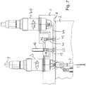
- Fig. 1
- ein Farbwechselsystem in einer ersten Ausführung und zwar in einer Situation, in der der Stator und der Auswahlkopf miteinander gekoppelt sind, so dass das Schaltventil geöffnet ist,
- Fig. 2
- die Situation wie in
Fig. 1 , wobei über einen Fluidanschluss ein Steuerfluid dem Medienventil zugeleitet wird, so dass dieses öffnet, - Fig. 3
- die Situation wie in
Fig. 1 , wobei bei einem geschlossenen Medienventil über eine Spülleitung ein Spülmittel der Medienleitung im Auswahlkopf zugeleitet wird, - Fig. 4
- eine Situation, bei der der Stator und der Auswahlkopf voneinander entkoppelt sind und weiterhin über eine Spülleitung der Medienleitung ein Spülmittel zugeleitet wird,
- Fig. 5
- einen vergrößerten Ausschnitt aus einem Farbwechselsystem in einer zweiten Ausführung und zwar in einer Situation, in der der Stator und der Auswahlkopf miteinander gekoppelt sind,
- Fig. 6
- eine Situation der zweiten Ausführung, bei der der Stator und der Auswahlkopf voneinander entkoppelt sind und weiterhin über eine Spülleitung der Medienleitung ein Spülmittel zugeleitet wird,
- Fig. 7
- einen Stator mit einem Medienventil und einem Umlaufventil, wobei der Auswahlkopf am Stator angedockt ist, aber am Fluidanschluss kein Steuerdruck anliegt, so dass sich das Medienventil und das Umlaufventil in ihren Grundstellungen befinden,
- Fig. 8
- dieselbe Situation wie in
Fig. 7 , allerdings liegt ein Steuerdruck an, so dass das Medienventil und das Umlaufventil umgeschaltet sind, - Fig. 9
- einen Stator mit einem Medienventil und einem Umlaufventil, wobei der Auswahlkopf vom Stator entfernt ist, so dass die Schaltventile geschlossen sind,
- Fig. 10
- eine vergrößerte Ansicht des Ventilschließkörpers und des Ventilsitzes von einem Medienventil und einem Umlaufventil.
- Fig. 1
- a color change system in a first embodiment, specifically in a situation in which the stator and the selection head are coupled to one another so that the switching valve is open,
- Fig. 2
- the situation as in
Fig. 1 , wherein a control fluid is fed to the media valve via a fluid connection so that it opens, - Fig. 3
- the situation as in
Fig. 1 , With a closed media valve, a flushing agent is fed to the media line in the selection head via a flushing line, - Fig. 4
- a situation in which the stator and the selection head are decoupled from one another and a flushing agent is also supplied to the media line via a flushing line,
- Fig. 5
- 3 shows an enlarged section of a color change system in a second embodiment, specifically in a situation in which the stator and the selection head are coupled to one another,
- Fig. 6
- a situation of the second embodiment, in which the stator and the selection head are decoupled from one another and furthermore a detergent is supplied to the media line via a flushing line,
- Fig. 7
- a stator with a media valve and a circulation valve, the selection head being docked on the stator, but there being no control pressure at the fluid connection, so that the media valve and the circulation valve are in their basic positions,
- Fig. 8
- the same situation as in
Fig. 7 , however, there is a control pressure so that the media valve and the circulation valve are switched, - Fig. 9
- a stator with a media valve and a circulation valve, the selection head being removed from the stator, so that the switching valves are closed,
- Fig. 10
- an enlarged view of the valve closing body and the valve seat of a media valve and a circulation valve.
Die einzelnen Positionen des Systems werden anhand der
Das Farbwechselsystem besteht aus einem Stator 1 und einem Auswahlkopf 2, der z. B. als Rotor ausgeführt ist.The color change system consists of a stator 1 and a
Im Stator 1 befinden sich eine Vielzahl von Medienventilen 3, die jeweils mit einer Medienzuführung 4 verbunden sind und deren Medienventilauslässe 5 in der Frontseite 6 des Stators 1 liegen. Die Medienventile 3 liegen z. B. auf einem Kreis, so dass durch eine Drehung des Auswahlkopfes 2 dessen Medienleitung 7, die in einem Medieneinlass 8 in der Rückseite 9 des Auswahlkopfes 2 mündet, zur Deckung mit einem der Medienventilauslässe 5 gebracht werden kann.In the stator 1 there are a large number of
In der
Das Medienventil 3 ist druckluftgesteuert (im Prinzip ist auch eine hydraulische Steuerung möglich). Dazu ist der Ventilschließkörper mit einem von einem Fluiddruck beaufschlagbaren und innerhalb des Stators angeordneten Stellkolben verbunden, der an eine Steuerdruckkammer angrenzt. Der Stellkolben ist hier nicht dargestellt. Eine geeignete Ausführung des Medienventils mit einem Stellkörper ist aber in der
Jedes Medienventil 3 ist in einer Patrone eingebettet, die in einer Vertiefung auf der Rückseite des Stators 1 befestigt ist. Innerhalb der Patrone befindet sich ein hohler Ventilschaft, an dessen Kopf der konisch ausgebildete Ventilschließkörper angebracht ist. Dieser wirkt mit dem ebenfalls konisch ausgeführten Ventilsitz zusammen, der im Kopf der Patrone ausgebildet ist. Die hohle Ausführung des Ventilschaftes bewirkt eine strömumgsgünstige Führung des Mediums.Each
Der Stator 1 besitzt an seiner Rückseite einen Fluid- bzw. Druckluftanschluss 16 an einer Ringleitung 17, die über jeweils einen Steuerkanal 18 mit der Betätigung der Medienventile 3 verbunden ist. In jedem dieser Steuerkanäle 18 befindet sich ein Schaltventil 19, das einen hantelförmigen Schließkörper 20 aufweist, wobei der eine Kopf des Schließkörpers 20 an einem Dichtring 21 anlegbar ist, so dass der Steuerkanal 18 geschlossen wird.The back of the stator 1 has a fluid or
Die Betätigung des Schließkörpers 20 erfolgt mittels eines Nockens 22, der sich an der Rückseite 9 des Auswahlkopfes 2 befindet und der in eine Bohrung 23 eintaucht, in der sich das Schaltventil 19 befindet.The closing
Die
Die
Zum Wechseln einer Farbe wird zunächst, wie in
Wird nun der Auswahlkopf 2 zurückgezogen (siehe
In den
In der
Die hier gezeigte Anordnung von Medienventil 3 und Umlaufventil 40 dient der Klärung der Funktionsweise. In der Regel werden so viele Medienventile 3 benötigt, dass diese auf zwei Kreise am Stator 1 angeordnet sind. Dabei sind dann vorzugsweise die Medienventile 3 und die Umlaufventile 40 in unterschiedlichen Kreisen - versetzt zueinander - angeordnet. Dies macht es in der Regel auch notwendig, zwei parallele Schaltventile (19, 41) vorzusehen, nämlich eines für das Medienventil 3 und ein Zusatzschaltventil 41 für das Umlaufventil 40, wie dies hier dargestellt ist. Funktionsmäßig ist aber nur ein Schaltventil notwendig, das beide Steuerkanäle 18, 42 öffnet bzw. schließt.The arrangement of
Wie aus der
In der in
Grundsätzlich kann der Zusatzsteuerkanal 42 zum Umlaufventil 40 auch vom Schaltventil 19 des Medienventils 3 kontrolliert werden, so dass auf das gezeigte zusätzliche Schaltventil 41 für das Umlaufventil 40 verzichtet werden kann.In principle, the
Die
Ein Medium, das an der Medienzuführung 4 des Medienventils anliegt, kann, wie im Zusammenhang mit den
Da auch die Nocken 22, 45 von den Schaltventilen 19, 41 entfernt sind, sind diese geschlossen, so dass unabhängig von einer Druckbeaufschlagung am Fluidanschluss 16, der ggf. notwendig ist, um die anderen Medienventile zu öffnen, jedenfalls das gezeigte Medienventil 3 geschlossen und das Umlaufventil 40 geöffnet ist.Since the
Dies erlaubt eine Spülung der beiden Ventile. Dazu wird zunächst an der Medienzuführung 4 des Medienventils ein so genanntes Schiebemedium eingelassen, das die aktuelle Farbe aus dem Medienventil 3 und dem Umlaufventil 40 hinausschiebt, und danach im Wechsel Spülmedium und Luft nachgeführt wird, um das Medienventil, den Verbindungskanal 44 und das Umlaufventil vom Lackresten zu befreien. Danach ist es möglich, über die Medienzuführung 4 des Medienventils 3 eine neue Lackfarbe anzusetzen.This allows the two valves to be flushed. For this purpose, a so-called sliding medium is first inserted into the media feed 4 of the media valve, which pushes the current color out of the
Dieser Spülvorgang erfolgt, während das System insgesamt weiterarbeitet und ggf. Farbe an einem anderen Medienventil ausgetragen wird.This flushing process takes place while the system as a whole continues to work and, if necessary, paint is discharged from another media valve.
Um insbesondere den Bereich des Medienventils 3 um den Ventilschließkörper 24 und den Ventildichtsitz 25 sorgfältig zu reinigen, ist - wie die
Der Kopf taucht in eine Hülse 52 ein, in der der Ventildichtsitz 25 des Medienventils 3 ausgebildet ist und in dessen äußerer Mantelfläche eine umlaufende Nut verläuft. Da die Mantelfläche an der Wand einer Medienventilaufnahmebohrung im Stator 1 anliegt, entsteht ein Ringkanal 53, der über eine Querbohrung 54 in der Hülse 52 mit dem Hohlkanal 50 in Verbindung steht.The head dips into a
Die Querbohrung 54 befindet sich auf Höhe der seitlichen Ausgänge 51 des Ventilschließkörpers 24, wenn dieser sich in einer Schließposition befindet.The transverse bore 54 is located at the level of the lateral outputs 51 of the
Der Verbindungskanal 44 mündet gegenüberliegend zur Querbohrung 54 in den Ringkanal 53 ein.The connecting
Die Luft bzw. das Spülmedium, die/das aus den seitlichen Ausgängen 51 heraustritt, ist daher gezwungen, den Ventilschließkörper 24 außen zu umfließen, um über die Querbohrung 54 in den Ringkanal 53 zu gelangen und von dort in Richtung auf den Verbindungskanal 44 strömen zu können. Diese gegenüberliegende Anordnung von Verbindungskanal 44 und Querbohrung 54 stellt sicher, dass der Ventilschließkörper 24 allseitig gereinigt wird.
Claims (9)
- A colour change system with a stator (1) comprising a front side, the stator having a plurality of media valves (3) the inlets of which are connected each to a media supply (4) and the outlets (5) of which feed into the front side of the stator (1), wherein each media valve (3) within a valve chamber formed in the stator comprises a valve closing body (24), which is movable against a valve sealing seat (25) pointing into the valve chamber, wherein the valve closing body is connected to a control piston arranged within the stator and subjectable to fluid pressure, the control piston being adjacent to a control pressure chamber, and with a selection head (2) arranged upstream of the front side of the stator (1), which is rotatable about an axis extending vertically to the stator front side and/or is movable in parallel to the stator front side, wherein the selection head (2) comprises a media inlet (8) on its back facing the stator front side, which by a rotation and/or a move of the selection head (2) can be brought to overlap with one of the media valve outlets (5), and wherein the selection head (2) comprises a media line (7), which connects the media inlet (8) to a media discharge of the system, wherein a rinsing line (11) feeds into the media line (7), the rinsing line containing a rinsing non-return valve (12) opening in direction of the media line (7), characterised in that a blocking non-return valve (10) is arranged in the media inlet (8) in direct connection to the back of the selection head (2), which blocks in direction of the back of the selection head (2), and in that the rinsing line (11) containing the rinsing non-return valve (12) feeds into the media line (7) downstream of the blocking non-return valve (10).
- The colour-change system according to claim 1, characterised in that the stator (1) comprises a fluid port (16), which is connected via respective control channels (18) to the control pressure chambers of the media valves (3), in order to switch the same, in that a switching valve (19) mechanically operable by a cam is present in each of these control channels (18), and in that the back of the selection head (2) has a cam (22) attached to it, which when the back of the selection head is brought into contact with the front side of the stator, the switching valve (19) opens, which belongs to the media valve (3), the media valve outlet (5) of which in the stator is connected to the media inlet (8) in the selection head (2).
- The colour-change system according to claim 2, characterised in that the selection head (2) is movable vertically to the stator front side, in that the cam (22) is formed on the back of the selection head (2) and vertically protrudes from the same, in that the switching valves (19) are accommodated in bores (23) feeding into the front side of the stator, wherein the cam (22) is adapted to plunge into the bores, and in that the bores are each oriented in the same way to the media valve outlets (5) as the cam (22) is to the media inlet (8).
- The colour-change system according to claim 1, characterised in that the stator (1) has, for each media valve (3), a fluid port (32) on its front side (6), which is connected via a control channel (31) to the control pressure chamber of the respective media valve (3) in order to switch the same, wherein each control channel (31) contains a non-return valve (33), which blocks in direction of the fluid port (32), and in that a collecting control channel (34) extends in the selection head (2), which feeds into the back of the selection head (2), wherein the mouth of the collecting control channel (34) is aligned with the fluid port (32), the control channel (31) of which leads to the media valve (3), the media valve outlet (5) of which overlaps with the media inlet (8).
- The colour-change system according to one of the preceding claims, characterised in that at least one of the media valves (3) has a circulation valve (40) in the stator (1) associated with it, the outlet of which has a connection to the inlet of the media valve (3), and in that the media valve (3) is configured such that it is open when its control pressure chamber is pressurised, in that the valve closing body of the circulation valve (40) is connected to a control piston arranged within the stator (1) and subjectable to fluid pressure, the control piston being adjacent to a control pressure chamber, wherein the circulation valve (40) is configured such that it is closed when its control pressure chamber is pressurised.
- The colour-change system according to claim 5, characterised in that the control pressure chamber of the circulation valve (40) is connected to the fluid port (16) via a switchable additional control channel (42) .
- The colour-change system according to claim 6, characterised in that an additional switching valve (41) is present in the additional control channel (42) .
- The colour-change system according to claim 7, characterised in that an additional switching valve (41) mechanically operable by a cam (45) is present in the additional control channel (42), and in that an additional cam (45) is attached on the back of the selection head (2), which when the back of the selection head (2) is brought into contact with the front side of the stator (1), the addition switching valve (41) opens which belongs to the circulation valve (40).
- The colour-change system according to claim 5, characterised in that the stator (1), for each media valve (3), has a fluid port (32) on its front side (6), which is connected via a control channel (31) to the control pressure chamber of the respective media valve (3) in order to switch the same, wherein a non-return valve (33) is present in each control channel (31), which blocks in direction of the fluid port (32), and in that a collecting control channel (34) extends in the selection head (2), which feeds into the back of the selection head (2), wherein the mouth of the collecting control channel (34) is aligned with the fluid port (32), the control channel (31) of which leads to the media valve (3), the media valve outlet (5) of which overlaps with the media inlet (8), and in that an additional control channel (42) branches off from the control channel (31) of at least one of the media valves (3) in direction of the circulation valve (40) .
Priority Applications (1)
| Application Number | Priority Date | Filing Date | Title |
|---|---|---|---|
| EP19197160.5A EP3610955A1 (en) | 2015-04-15 | 2016-04-15 | Colour changing system |
Applications Claiming Priority (2)
| Application Number | Priority Date | Filing Date | Title |
|---|---|---|---|
| DE102015105774 | 2015-04-15 | ||
| PCT/DE2016/100181 WO2016165698A1 (en) | 2015-04-15 | 2016-04-15 | Colour change system |
Related Child Applications (2)
| Application Number | Title | Priority Date | Filing Date |
|---|---|---|---|
| EP19197160.5A Division EP3610955A1 (en) | 2015-04-15 | 2016-04-15 | Colour changing system |
| EP19197160.5A Division-Into EP3610955A1 (en) | 2015-04-15 | 2016-04-15 | Colour changing system |
Publications (2)
| Publication Number | Publication Date |
|---|---|
| EP3283231A1 EP3283231A1 (en) | 2018-02-21 |
| EP3283231B1 true EP3283231B1 (en) | 2020-07-29 |
Family
ID=56117458
Family Applications (2)
| Application Number | Title | Priority Date | Filing Date |
|---|---|---|---|
| EP16728214.4A Active EP3283231B1 (en) | 2015-04-15 | 2016-04-15 | Colour change system |
| EP19197160.5A Withdrawn EP3610955A1 (en) | 2015-04-15 | 2016-04-15 | Colour changing system |
Family Applications After (1)
| Application Number | Title | Priority Date | Filing Date |
|---|---|---|---|
| EP19197160.5A Withdrawn EP3610955A1 (en) | 2015-04-15 | 2016-04-15 | Colour changing system |
Country Status (3)
| Country | Link |
|---|---|
| EP (2) | EP3283231B1 (en) |
| DE (2) | DE112016001728A5 (en) |
| WO (1) | WO2016165698A1 (en) |
Families Citing this family (1)
| Publication number | Priority date | Publication date | Assignee | Title |
|---|---|---|---|---|
| CN107694856B (en) * | 2017-11-17 | 2023-05-23 | 常德烟草机械有限责任公司 | Automatic docking system |
Family Cites Families (8)
| Publication number | Priority date | Publication date | Assignee | Title |
|---|---|---|---|---|
| US3240225A (en) * | 1963-01-17 | 1966-03-15 | Benjamin G Barrows | Selecting and purging apparatus |
| DE4339302C2 (en) * | 1993-11-18 | 1999-12-30 | Abb Patent Gmbh | Color change block with leakage indicators |
| FR2803776B1 (en) * | 2000-01-14 | 2002-06-07 | Sames Sa | COATING PRODUCT SPRAYING SYSTEM |
| US6945483B2 (en) * | 2000-12-07 | 2005-09-20 | Fanuc Robotics North America, Inc. | Electrostatic painting apparatus with paint filling station and method for operating same |
| DE20122759U1 (en) | 2001-03-29 | 2007-07-19 | Dürr Systems GmbH | Color change system for unit for series coating of work pieces e.g. vehicle chassis, has drive device, with which connection valve and supply valve are able to couple together and separate from each other in given direction of movement |
| EP2075073B1 (en) | 2007-12-28 | 2012-10-03 | INDUSTRA Industrieanlagen - Maschinen und Teile GmbH | Colour change system and method for changing colours |
| JP5596950B2 (en) * | 2009-09-23 | 2014-09-24 | ランズバーグ・インダストリー株式会社 | Paint cartridge for electrostatic coating machine and electrostatic coating machine including the same |
| DE102015102332A1 (en) | 2014-02-18 | 2015-08-20 | Apson Lackiertechnik Gmbh | Color Change System |
-
2016
- 2016-04-15 DE DE112016001728.6T patent/DE112016001728A5/en not_active Withdrawn
- 2016-04-15 EP EP16728214.4A patent/EP3283231B1/en active Active
- 2016-04-15 DE DE102016107042.4A patent/DE102016107042A1/en not_active Withdrawn
- 2016-04-15 WO PCT/DE2016/100181 patent/WO2016165698A1/en active Application Filing
- 2016-04-15 EP EP19197160.5A patent/EP3610955A1/en not_active Withdrawn
Non-Patent Citations (1)
| Title |
|---|
| None * |
Also Published As
| Publication number | Publication date |
|---|---|
| EP3610955A1 (en) | 2020-02-19 |
| WO2016165698A1 (en) | 2016-10-20 |
| DE102016107042A1 (en) | 2016-10-20 |
| DE112016001728A5 (en) | 2018-01-04 |
| EP3283231A1 (en) | 2018-02-21 |
Similar Documents
| Publication | Publication Date | Title |
|---|---|---|
| EP0061630B1 (en) | Flushable gear pump | |
| DE2043789C3 (en) | Device for spraying paint on a series of objects | |
| DE1285819B (en) | Multiple control valve | |
| DE102018204361B3 (en) | Multiway valve and method for its operation | |
| CH623927A5 (en) | ||
| EP2065100B1 (en) | Separating agent spraying device for a casting machine | |
| EP3283231B1 (en) | Colour change system | |
| DE102015102332A1 (en) | Color Change System | |
| DE1621857A1 (en) | Spray gun | |
| EP2075073B1 (en) | Colour change system and method for changing colours | |
| EP3033181B1 (en) | Changing device for coating media and coating system for coating objects | |
| EP1991791B1 (en) | Valve bank comprising a safety valve | |
| EP2554275B1 (en) | Colour changer | |
| EP1250964B1 (en) | Method and valve arrangement for supplying liquid to a disconnectable element of a coating installation | |
| EP1468745B1 (en) | Spray element for a sprayer head | |
| DE19633191C2 (en) | Changeover valve for a pressure medium | |
| DE102007007645B3 (en) | Valve i.e. impulse valve, has retaining device assigned to end sections of valve slider in such manner that valve slider switchable between two switching positions is detachably lockable in both switching positions | |
| EP1384518B1 (en) | Method and valve arrangement for controlling colour change in a coating installation | |
| DE102016113505A1 (en) | Color Change System | |
| DE3227656C2 (en) | ||
| DE19641073A1 (en) | Pneumatic valve for controlling air flow to esp. paint spray equipment | |
| EP0496052B1 (en) | Device to spray a fluid bonding agent, especially bitumen | |
| EP2606981B1 (en) | Colour change module and colour changer | |
| DE4214778C2 (en) | Spray coating device for liquid paint | |
| DE3709557C1 (en) | Device for forming a plastic reaction mixture |
Legal Events
| Date | Code | Title | Description |
|---|---|---|---|
| STAA | Information on the status of an ep patent application or granted ep patent |
Free format text: STATUS: THE INTERNATIONAL PUBLICATION HAS BEEN MADE |
|
| PUAI | Public reference made under article 153(3) epc to a published international application that has entered the european phase |
Free format text: ORIGINAL CODE: 0009012 |
|
| STAA | Information on the status of an ep patent application or granted ep patent |
Free format text: STATUS: REQUEST FOR EXAMINATION WAS MADE |
|
| 17P | Request for examination filed |
Effective date: 20171012 |
|
| AK | Designated contracting states |
Kind code of ref document: A1 Designated state(s): AL AT BE BG CH CY CZ DE DK EE ES FI FR GB GR HR HU IE IS IT LI LT LU LV MC MK MT NL NO PL PT RO RS SE SI SK SM TR |
|
| AX | Request for extension of the european patent |
Extension state: BA ME |
|
| DAV | Request for validation of the european patent (deleted) | ||
| DAX | Request for extension of the european patent (deleted) | ||
| RIC1 | Information provided on ipc code assigned before grant |
Ipc: B05B 12/14 20060101ALI20161025BHEP Ipc: B05B 15/02 20181130AFI20161025BHEP |
|
| RIC1 | Information provided on ipc code assigned before grant |
Ipc: B05B 15/02 20060101AFI20161025BHEP Ipc: B05B 12/14 20060101ALI20161025BHEP |
|
| STAA | Information on the status of an ep patent application or granted ep patent |
Free format text: STATUS: EXAMINATION IS IN PROGRESS |
|
| 17Q | First examination report despatched |
Effective date: 20190418 |
|
| REG | Reference to a national code |
Ref country code: DE Ref legal event code: R079 Ref document number: 502016010662 Country of ref document: DE Free format text: PREVIOUS MAIN CLASS: B05B0015020000 Ipc: B05B0012140000 |
|
| RIC1 | Information provided on ipc code assigned before grant |
Ipc: B08B 9/027 20060101ALI20191203BHEP Ipc: B05B 12/14 20060101AFI20191203BHEP Ipc: B05B 15/55 20180101ALI20191203BHEP |
|
| GRAP | Despatch of communication of intention to grant a patent |
Free format text: ORIGINAL CODE: EPIDOSNIGR1 |
|
| STAA | Information on the status of an ep patent application or granted ep patent |
Free format text: STATUS: GRANT OF PATENT IS INTENDED |
|
| GRAS | Grant fee paid |
Free format text: ORIGINAL CODE: EPIDOSNIGR3 |
|
| INTG | Intention to grant announced |
Effective date: 20200210 |
|
| GRAA | (expected) grant |
Free format text: ORIGINAL CODE: 0009210 |
|
| STAA | Information on the status of an ep patent application or granted ep patent |
Free format text: STATUS: THE PATENT HAS BEEN GRANTED |
|
| AK | Designated contracting states |
Kind code of ref document: B1 Designated state(s): AL AT BE BG CH CY CZ DE DK EE ES FI FR GB GR HR HU IE IS IT LI LT LU LV MC MK MT NL NO PL PT RO RS SE SI SK SM TR |
|
| REG | Reference to a national code |
Ref country code: CH Ref legal event code: EP |
|
| REG | Reference to a national code |
Ref country code: DE Ref legal event code: R096 Ref document number: 502016010662 Country of ref document: DE |
|
| REG | Reference to a national code |
Ref country code: AT Ref legal event code: REF Ref document number: 1295177 Country of ref document: AT Kind code of ref document: T Effective date: 20200815 |
|
| REG | Reference to a national code |
Ref country code: IE Ref legal event code: FG4D Free format text: LANGUAGE OF EP DOCUMENT: GERMAN |
|
| REG | Reference to a national code |
Ref country code: LT Ref legal event code: MG4D |
|
| REG | Reference to a national code |
Ref country code: NL Ref legal event code: MP Effective date: 20200729 |
|
| PG25 | Lapsed in a contracting state [announced via postgrant information from national office to epo] |
Ref country code: HR Free format text: LAPSE BECAUSE OF FAILURE TO SUBMIT A TRANSLATION OF THE DESCRIPTION OR TO PAY THE FEE WITHIN THE PRESCRIBED TIME-LIMIT Effective date: 20200729 Ref country code: LT Free format text: LAPSE BECAUSE OF FAILURE TO SUBMIT A TRANSLATION OF THE DESCRIPTION OR TO PAY THE FEE WITHIN THE PRESCRIBED TIME-LIMIT Effective date: 20200729 Ref country code: FI Free format text: LAPSE BECAUSE OF FAILURE TO SUBMIT A TRANSLATION OF THE DESCRIPTION OR TO PAY THE FEE WITHIN THE PRESCRIBED TIME-LIMIT Effective date: 20200729 Ref country code: PT Free format text: LAPSE BECAUSE OF FAILURE TO SUBMIT A TRANSLATION OF THE DESCRIPTION OR TO PAY THE FEE WITHIN THE PRESCRIBED TIME-LIMIT Effective date: 20201130 Ref country code: SE Free format text: LAPSE BECAUSE OF FAILURE TO SUBMIT A TRANSLATION OF THE DESCRIPTION OR TO PAY THE FEE WITHIN THE PRESCRIBED TIME-LIMIT Effective date: 20200729 Ref country code: ES Free format text: LAPSE BECAUSE OF FAILURE TO SUBMIT A TRANSLATION OF THE DESCRIPTION OR TO PAY THE FEE WITHIN THE PRESCRIBED TIME-LIMIT Effective date: 20200729 Ref country code: GR Free format text: LAPSE BECAUSE OF FAILURE TO SUBMIT A TRANSLATION OF THE DESCRIPTION OR TO PAY THE FEE WITHIN THE PRESCRIBED TIME-LIMIT Effective date: 20201030 Ref country code: NO Free format text: LAPSE BECAUSE OF FAILURE TO SUBMIT A TRANSLATION OF THE DESCRIPTION OR TO PAY THE FEE WITHIN THE PRESCRIBED TIME-LIMIT Effective date: 20201029 Ref country code: BG Free format text: LAPSE BECAUSE OF FAILURE TO SUBMIT A TRANSLATION OF THE DESCRIPTION OR TO PAY THE FEE WITHIN THE PRESCRIBED TIME-LIMIT Effective date: 20201029 |
|
| PG25 | Lapsed in a contracting state [announced via postgrant information from national office to epo] |
Ref country code: LV Free format text: LAPSE BECAUSE OF FAILURE TO SUBMIT A TRANSLATION OF THE DESCRIPTION OR TO PAY THE FEE WITHIN THE PRESCRIBED TIME-LIMIT Effective date: 20200729 Ref country code: RS Free format text: LAPSE BECAUSE OF FAILURE TO SUBMIT A TRANSLATION OF THE DESCRIPTION OR TO PAY THE FEE WITHIN THE PRESCRIBED TIME-LIMIT Effective date: 20200729 Ref country code: PL Free format text: LAPSE BECAUSE OF FAILURE TO SUBMIT A TRANSLATION OF THE DESCRIPTION OR TO PAY THE FEE WITHIN THE PRESCRIBED TIME-LIMIT Effective date: 20200729 Ref country code: IS Free format text: LAPSE BECAUSE OF FAILURE TO SUBMIT A TRANSLATION OF THE DESCRIPTION OR TO PAY THE FEE WITHIN THE PRESCRIBED TIME-LIMIT Effective date: 20201129 |
|
| PG25 | Lapsed in a contracting state [announced via postgrant information from national office to epo] |
Ref country code: NL Free format text: LAPSE BECAUSE OF FAILURE TO SUBMIT A TRANSLATION OF THE DESCRIPTION OR TO PAY THE FEE WITHIN THE PRESCRIBED TIME-LIMIT Effective date: 20200729 |
|
| PG25 | Lapsed in a contracting state [announced via postgrant information from national office to epo] |
Ref country code: IT Free format text: LAPSE BECAUSE OF FAILURE TO SUBMIT A TRANSLATION OF THE DESCRIPTION OR TO PAY THE FEE WITHIN THE PRESCRIBED TIME-LIMIT Effective date: 20200729 Ref country code: EE Free format text: LAPSE BECAUSE OF FAILURE TO SUBMIT A TRANSLATION OF THE DESCRIPTION OR TO PAY THE FEE WITHIN THE PRESCRIBED TIME-LIMIT Effective date: 20200729 Ref country code: CZ Free format text: LAPSE BECAUSE OF FAILURE TO SUBMIT A TRANSLATION OF THE DESCRIPTION OR TO PAY THE FEE WITHIN THE PRESCRIBED TIME-LIMIT Effective date: 20200729 Ref country code: DK Free format text: LAPSE BECAUSE OF FAILURE TO SUBMIT A TRANSLATION OF THE DESCRIPTION OR TO PAY THE FEE WITHIN THE PRESCRIBED TIME-LIMIT Effective date: 20200729 Ref country code: SM Free format text: LAPSE BECAUSE OF FAILURE TO SUBMIT A TRANSLATION OF THE DESCRIPTION OR TO PAY THE FEE WITHIN THE PRESCRIBED TIME-LIMIT Effective date: 20200729 Ref country code: RO Free format text: LAPSE BECAUSE OF FAILURE TO SUBMIT A TRANSLATION OF THE DESCRIPTION OR TO PAY THE FEE WITHIN THE PRESCRIBED TIME-LIMIT Effective date: 20200729 |
|
| REG | Reference to a national code |
Ref country code: DE Ref legal event code: R097 Ref document number: 502016010662 Country of ref document: DE |
|
| PG25 | Lapsed in a contracting state [announced via postgrant information from national office to epo] |
Ref country code: AL Free format text: LAPSE BECAUSE OF FAILURE TO SUBMIT A TRANSLATION OF THE DESCRIPTION OR TO PAY THE FEE WITHIN THE PRESCRIBED TIME-LIMIT Effective date: 20200729 |
|
| PLBE | No opposition filed within time limit |
Free format text: ORIGINAL CODE: 0009261 |
|
| STAA | Information on the status of an ep patent application or granted ep patent |
Free format text: STATUS: NO OPPOSITION FILED WITHIN TIME LIMIT |
|
| PG25 | Lapsed in a contracting state [announced via postgrant information from national office to epo] |
Ref country code: SK Free format text: LAPSE BECAUSE OF FAILURE TO SUBMIT A TRANSLATION OF THE DESCRIPTION OR TO PAY THE FEE WITHIN THE PRESCRIBED TIME-LIMIT Effective date: 20200729 |
|
| 26N | No opposition filed |
Effective date: 20210430 |
|
| PGFP | Annual fee paid to national office [announced via postgrant information from national office to epo] |
Ref country code: DE Payment date: 20210202 Year of fee payment: 6 Ref country code: FR Payment date: 20210423 Year of fee payment: 6 |
|
| PG25 | Lapsed in a contracting state [announced via postgrant information from national office to epo] |
Ref country code: SI Free format text: LAPSE BECAUSE OF FAILURE TO SUBMIT A TRANSLATION OF THE DESCRIPTION OR TO PAY THE FEE WITHIN THE PRESCRIBED TIME-LIMIT Effective date: 20200729 |
|
| PG25 | Lapsed in a contracting state [announced via postgrant information from national office to epo] |
Ref country code: MC Free format text: LAPSE BECAUSE OF FAILURE TO SUBMIT A TRANSLATION OF THE DESCRIPTION OR TO PAY THE FEE WITHIN THE PRESCRIBED TIME-LIMIT Effective date: 20200729 |
|
| GBPC | Gb: european patent ceased through non-payment of renewal fee |
Effective date: 20210415 |
|
| PG25 | Lapsed in a contracting state [announced via postgrant information from national office to epo] |
Ref country code: LU Free format text: LAPSE BECAUSE OF NON-PAYMENT OF DUE FEES Effective date: 20210415 |
|
| REG | Reference to a national code |
Ref country code: BE Ref legal event code: MM Effective date: 20210430 |
|
| PG25 | Lapsed in a contracting state [announced via postgrant information from national office to epo] |
Ref country code: GB Free format text: LAPSE BECAUSE OF NON-PAYMENT OF DUE FEES Effective date: 20210415 Ref country code: CH Free format text: LAPSE BECAUSE OF NON-PAYMENT OF DUE FEES Effective date: 20210430 Ref country code: LI Free format text: LAPSE BECAUSE OF NON-PAYMENT OF DUE FEES Effective date: 20210430 |
|
| PG25 | Lapsed in a contracting state [announced via postgrant information from national office to epo] |
Ref country code: IE Free format text: LAPSE BECAUSE OF NON-PAYMENT OF DUE FEES Effective date: 20210415 |
|
| PG25 | Lapsed in a contracting state [announced via postgrant information from national office to epo] |
Ref country code: IS Free format text: LAPSE BECAUSE OF FAILURE TO SUBMIT A TRANSLATION OF THE DESCRIPTION OR TO PAY THE FEE WITHIN THE PRESCRIBED TIME-LIMIT Effective date: 20201129 |
|
| REG | Reference to a national code |
Ref country code: AT Ref legal event code: MM01 Ref document number: 1295177 Country of ref document: AT Kind code of ref document: T Effective date: 20210415 |
|
| PG25 | Lapsed in a contracting state [announced via postgrant information from national office to epo] |
Ref country code: BE Free format text: LAPSE BECAUSE OF NON-PAYMENT OF DUE FEES Effective date: 20210430 |
|
| PG25 | Lapsed in a contracting state [announced via postgrant information from national office to epo] |
Ref country code: AT Free format text: LAPSE BECAUSE OF NON-PAYMENT OF DUE FEES Effective date: 20210415 |
|
| REG | Reference to a national code |
Ref country code: DE Ref legal event code: R119 Ref document number: 502016010662 Country of ref document: DE |
|
| PG25 | Lapsed in a contracting state [announced via postgrant information from national office to epo] |
Ref country code: FR Free format text: LAPSE BECAUSE OF NON-PAYMENT OF DUE FEES Effective date: 20220430 Ref country code: DE Free format text: LAPSE BECAUSE OF NON-PAYMENT OF DUE FEES Effective date: 20221103 |
|
| PG25 | Lapsed in a contracting state [announced via postgrant information from national office to epo] |
Ref country code: HU Free format text: LAPSE BECAUSE OF FAILURE TO SUBMIT A TRANSLATION OF THE DESCRIPTION OR TO PAY THE FEE WITHIN THE PRESCRIBED TIME-LIMIT; INVALID AB INITIO Effective date: 20160415 |
|
| PG25 | Lapsed in a contracting state [announced via postgrant information from national office to epo] |
Ref country code: CY Free format text: LAPSE BECAUSE OF FAILURE TO SUBMIT A TRANSLATION OF THE DESCRIPTION OR TO PAY THE FEE WITHIN THE PRESCRIBED TIME-LIMIT Effective date: 20200729 |