EP3282997B1 - Integrated medical imaging and surgical robotic system - Google Patents
Integrated medical imaging and surgical robotic system Download PDFInfo
- Publication number
- EP3282997B1 EP3282997B1 EP16780883.1A EP16780883A EP3282997B1 EP 3282997 B1 EP3282997 B1 EP 3282997B1 EP 16780883 A EP16780883 A EP 16780883A EP 3282997 B1 EP3282997 B1 EP 3282997B1
- Authority
- EP
- European Patent Office
- Prior art keywords
- patient
- gantry
- robotic arm
- support member
- imaging
- Prior art date
- Legal status (The legal status is an assumption and is not a legal conclusion. Google has not performed a legal analysis and makes no representation as to the accuracy of the status listed.)
- Active
Links
- 238000002059 diagnostic imaging Methods 0.000 title description 2
- 238000003384 imaging method Methods 0.000 claims description 137
- 238000001356 surgical procedure Methods 0.000 claims description 38
- 239000012636 effector Substances 0.000 description 57
- 238000000034 method Methods 0.000 description 29
- 230000007246 mechanism Effects 0.000 description 27
- 230000003287 optical effect Effects 0.000 description 14
- 238000013519 translation Methods 0.000 description 8
- 238000002591 computed tomography Methods 0.000 description 7
- 230000006870 function Effects 0.000 description 7
- 238000003780 insertion Methods 0.000 description 7
- 230000037431 insertion Effects 0.000 description 7
- 238000010586 diagram Methods 0.000 description 5
- 230000005855 radiation Effects 0.000 description 4
- 210000003484 anatomy Anatomy 0.000 description 3
- 230000006378 damage Effects 0.000 description 3
- 239000003550 marker Substances 0.000 description 3
- 230000008569 process Effects 0.000 description 3
- 230000004044 response Effects 0.000 description 3
- 241001465754 Metazoa Species 0.000 description 2
- 230000008901 benefit Effects 0.000 description 2
- 238000004590 computer program Methods 0.000 description 2
- 238000005516 engineering process Methods 0.000 description 2
- 239000000463 material Substances 0.000 description 2
- 210000000056 organ Anatomy 0.000 description 2
- 229920000049 Carbon (fiber) Polymers 0.000 description 1
- 241000020993 Metria Species 0.000 description 1
- 208000027418 Wounds and injury Diseases 0.000 description 1
- 239000000853 adhesive Substances 0.000 description 1
- 230000001070 adhesive effect Effects 0.000 description 1
- 230000004888 barrier function Effects 0.000 description 1
- 239000008280 blood Substances 0.000 description 1
- 210000004369 blood Anatomy 0.000 description 1
- 210000004556 brain Anatomy 0.000 description 1
- 239000004917 carbon fiber Substances 0.000 description 1
- 230000008859 change Effects 0.000 description 1
- 238000004891 communication Methods 0.000 description 1
- 238000013170 computed tomography imaging Methods 0.000 description 1
- 238000013461 design Methods 0.000 description 1
- 239000003814 drug Substances 0.000 description 1
- 229940079593 drug Drugs 0.000 description 1
- 230000005670 electromagnetic radiation Effects 0.000 description 1
- 239000007943 implant Substances 0.000 description 1
- 208000014674 injury Diseases 0.000 description 1
- 238000012977 invasive surgical procedure Methods 0.000 description 1
- 238000005259 measurement Methods 0.000 description 1
- VNWKTOKETHGBQD-UHFFFAOYSA-N methane Chemical compound C VNWKTOKETHGBQD-UHFFFAOYSA-N 0.000 description 1
- 238000002324 minimally invasive surgery Methods 0.000 description 1
- 238000012986 modification Methods 0.000 description 1
- 230000004048 modification Effects 0.000 description 1
- 238000002600 positron emission tomography Methods 0.000 description 1
- 238000012545 processing Methods 0.000 description 1
- 238000011084 recovery Methods 0.000 description 1
- 230000029058 respiratory gaseous exchange Effects 0.000 description 1
- 238000002603 single-photon emission computed tomography Methods 0.000 description 1
- 230000000638 stimulation Effects 0.000 description 1
- 239000003826 tablet Substances 0.000 description 1
- 239000012815 thermoplastic material Substances 0.000 description 1
- 238000012546 transfer Methods 0.000 description 1
- 238000012285 ultrasound imaging Methods 0.000 description 1
- 230000002861 ventricular Effects 0.000 description 1
Images


Classifications
-
- A—HUMAN NECESSITIES
- A61—MEDICAL OR VETERINARY SCIENCE; HYGIENE
- A61B—DIAGNOSIS; SURGERY; IDENTIFICATION
- A61B46/00—Surgical drapes
- A61B46/10—Surgical drapes specially adapted for instruments, e.g. microscopes
-
- A—HUMAN NECESSITIES
- A61—MEDICAL OR VETERINARY SCIENCE; HYGIENE
- A61B—DIAGNOSIS; SURGERY; IDENTIFICATION
- A61B34/00—Computer-aided surgery; Manipulators or robots specially adapted for use in surgery
- A61B34/20—Surgical navigation systems; Devices for tracking or guiding surgical instruments, e.g. for frameless stereotaxis
-
- A—HUMAN NECESSITIES
- A61—MEDICAL OR VETERINARY SCIENCE; HYGIENE
- A61B—DIAGNOSIS; SURGERY; IDENTIFICATION
- A61B34/00—Computer-aided surgery; Manipulators or robots specially adapted for use in surgery
- A61B34/30—Surgical robots
-
- A—HUMAN NECESSITIES
- A61—MEDICAL OR VETERINARY SCIENCE; HYGIENE
- A61B—DIAGNOSIS; SURGERY; IDENTIFICATION
- A61B5/00—Measuring for diagnostic purposes; Identification of persons
- A61B5/0033—Features or image-related aspects of imaging apparatus classified in A61B5/00, e.g. for MRI, optical tomography or impedance tomography apparatus; arrangements of imaging apparatus in a room
- A61B5/0036—Features or image-related aspects of imaging apparatus classified in A61B5/00, e.g. for MRI, optical tomography or impedance tomography apparatus; arrangements of imaging apparatus in a room including treatment, e.g., using an implantable medical device, ablating, ventilating
-
- A—HUMAN NECESSITIES
- A61—MEDICAL OR VETERINARY SCIENCE; HYGIENE
- A61B—DIAGNOSIS; SURGERY; IDENTIFICATION
- A61B5/00—Measuring for diagnostic purposes; Identification of persons
- A61B5/05—Detecting, measuring or recording for diagnosis by means of electric currents or magnetic fields; Measuring using microwaves or radio waves
- A61B5/055—Detecting, measuring or recording for diagnosis by means of electric currents or magnetic fields; Measuring using microwaves or radio waves involving electronic [EMR] or nuclear [NMR] magnetic resonance, e.g. magnetic resonance imaging
-
- A—HUMAN NECESSITIES
- A61—MEDICAL OR VETERINARY SCIENCE; HYGIENE
- A61B—DIAGNOSIS; SURGERY; IDENTIFICATION
- A61B6/00—Apparatus for radiation diagnosis, e.g. combined with radiation therapy equipment
- A61B6/12—Devices for detecting or locating foreign bodies
-
- A—HUMAN NECESSITIES
- A61—MEDICAL OR VETERINARY SCIENCE; HYGIENE
- A61B—DIAGNOSIS; SURGERY; IDENTIFICATION
- A61B6/00—Apparatus for radiation diagnosis, e.g. combined with radiation therapy equipment
- A61B6/54—Control of apparatus or devices for radiation diagnosis
- A61B6/547—Control of apparatus or devices for radiation diagnosis involving tracking of position of the device or parts of the device
-
- A—HUMAN NECESSITIES
- A61—MEDICAL OR VETERINARY SCIENCE; HYGIENE
- A61B—DIAGNOSIS; SURGERY; IDENTIFICATION
- A61B90/00—Instruments, implements or accessories specially adapted for surgery or diagnosis and not covered by any of the groups A61B1/00 - A61B50/00, e.g. for luxation treatment or for protecting wound edges
- A61B90/36—Image-producing devices or illumination devices not otherwise provided for
- A61B90/37—Surgical systems with images on a monitor during operation
-
- A—HUMAN NECESSITIES
- A61—MEDICAL OR VETERINARY SCIENCE; HYGIENE
- A61B—DIAGNOSIS; SURGERY; IDENTIFICATION
- A61B90/00—Instruments, implements or accessories specially adapted for surgery or diagnosis and not covered by any of the groups A61B1/00 - A61B50/00, e.g. for luxation treatment or for protecting wound edges
- A61B90/39—Markers, e.g. radio-opaque or breast lesions markers
-
- A—HUMAN NECESSITIES
- A61—MEDICAL OR VETERINARY SCIENCE; HYGIENE
- A61B—DIAGNOSIS; SURGERY; IDENTIFICATION
- A61B34/00—Computer-aided surgery; Manipulators or robots specially adapted for use in surgery
- A61B34/20—Surgical navigation systems; Devices for tracking or guiding surgical instruments, e.g. for frameless stereotaxis
- A61B2034/2046—Tracking techniques
- A61B2034/2055—Optical tracking systems
-
- A—HUMAN NECESSITIES
- A61—MEDICAL OR VETERINARY SCIENCE; HYGIENE
- A61B—DIAGNOSIS; SURGERY; IDENTIFICATION
- A61B90/00—Instruments, implements or accessories specially adapted for surgery or diagnosis and not covered by any of the groups A61B1/00 - A61B50/00, e.g. for luxation treatment or for protecting wound edges
- A61B90/36—Image-producing devices or illumination devices not otherwise provided for
- A61B90/37—Surgical systems with images on a monitor during operation
- A61B2090/376—Surgical systems with images on a monitor during operation using X-rays, e.g. fluoroscopy
- A61B2090/3762—Surgical systems with images on a monitor during operation using X-rays, e.g. fluoroscopy using computed tomography systems [CT]
-
- A—HUMAN NECESSITIES
- A61—MEDICAL OR VETERINARY SCIENCE; HYGIENE
- A61B—DIAGNOSIS; SURGERY; IDENTIFICATION
- A61B90/00—Instruments, implements or accessories specially adapted for surgery or diagnosis and not covered by any of the groups A61B1/00 - A61B50/00, e.g. for luxation treatment or for protecting wound edges
- A61B90/39—Markers, e.g. radio-opaque or breast lesions markers
- A61B2090/3937—Visible markers
-
- A—HUMAN NECESSITIES
- A61—MEDICAL OR VETERINARY SCIENCE; HYGIENE
- A61B—DIAGNOSIS; SURGERY; IDENTIFICATION
- A61B2505/00—Evaluating, monitoring or diagnosing in the context of a particular type of medical care
- A61B2505/05—Surgical care
-
- A—HUMAN NECESSITIES
- A61—MEDICAL OR VETERINARY SCIENCE; HYGIENE
- A61B—DIAGNOSIS; SURGERY; IDENTIFICATION
- A61B5/00—Measuring for diagnostic purposes; Identification of persons
- A61B5/0033—Features or image-related aspects of imaging apparatus classified in A61B5/00, e.g. for MRI, optical tomography or impedance tomography apparatus; arrangements of imaging apparatus in a room
-
- A—HUMAN NECESSITIES
- A61—MEDICAL OR VETERINARY SCIENCE; HYGIENE
- A61B—DIAGNOSIS; SURGERY; IDENTIFICATION
- A61B5/00—Measuring for diagnostic purposes; Identification of persons
- A61B5/06—Devices, other than using radiation, for detecting or locating foreign bodies ; determining position of probes within or on the body of the patient
- A61B5/061—Determining position of a probe within the body employing means separate from the probe, e.g. sensing internal probe position employing impedance electrodes on the surface of the body
- A61B5/064—Determining position of a probe within the body employing means separate from the probe, e.g. sensing internal probe position employing impedance electrodes on the surface of the body using markers
-
- A—HUMAN NECESSITIES
- A61—MEDICAL OR VETERINARY SCIENCE; HYGIENE
- A61B—DIAGNOSIS; SURGERY; IDENTIFICATION
- A61B5/00—Measuring for diagnostic purposes; Identification of persons
- A61B5/103—Detecting, measuring or recording devices for testing the shape, pattern, colour, size or movement of the body or parts thereof, for diagnostic purposes
- A61B5/11—Measuring movement of the entire body or parts thereof, e.g. head or hand tremor, mobility of a limb
- A61B5/1113—Local tracking of patients, e.g. in a hospital or private home
- A61B5/1114—Tracking parts of the body
-
- A—HUMAN NECESSITIES
- A61—MEDICAL OR VETERINARY SCIENCE; HYGIENE
- A61B—DIAGNOSIS; SURGERY; IDENTIFICATION
- A61B5/00—Measuring for diagnostic purposes; Identification of persons
- A61B5/103—Detecting, measuring or recording devices for testing the shape, pattern, colour, size or movement of the body or parts thereof, for diagnostic purposes
- A61B5/11—Measuring movement of the entire body or parts thereof, e.g. head or hand tremor, mobility of a limb
- A61B5/1126—Measuring movement of the entire body or parts thereof, e.g. head or hand tremor, mobility of a limb using a particular sensing technique
- A61B5/1127—Measuring movement of the entire body or parts thereof, e.g. head or hand tremor, mobility of a limb using a particular sensing technique using markers
-
- A—HUMAN NECESSITIES
- A61—MEDICAL OR VETERINARY SCIENCE; HYGIENE
- A61B—DIAGNOSIS; SURGERY; IDENTIFICATION
- A61B6/00—Apparatus for radiation diagnosis, e.g. combined with radiation therapy equipment
- A61B6/02—Devices for diagnosis sequentially in different planes; Stereoscopic radiation diagnosis
- A61B6/03—Computerised tomographs
- A61B6/032—Transmission computed tomography [CT]
-
- A—HUMAN NECESSITIES
- A61—MEDICAL OR VETERINARY SCIENCE; HYGIENE
- A61B—DIAGNOSIS; SURGERY; IDENTIFICATION
- A61B6/00—Apparatus for radiation diagnosis, e.g. combined with radiation therapy equipment
- A61B6/02—Devices for diagnosis sequentially in different planes; Stereoscopic radiation diagnosis
- A61B6/03—Computerised tomographs
- A61B6/037—Emission tomography
-
- A—HUMAN NECESSITIES
- A61—MEDICAL OR VETERINARY SCIENCE; HYGIENE
- A61B—DIAGNOSIS; SURGERY; IDENTIFICATION
- A61B6/00—Apparatus for radiation diagnosis, e.g. combined with radiation therapy equipment
- A61B6/04—Positioning of patients; Tiltable beds or the like
-
- A—HUMAN NECESSITIES
- A61—MEDICAL OR VETERINARY SCIENCE; HYGIENE
- A61B—DIAGNOSIS; SURGERY; IDENTIFICATION
- A61B6/00—Apparatus for radiation diagnosis, e.g. combined with radiation therapy equipment
- A61B6/44—Constructional features of apparatus for radiation diagnosis
- A61B6/4429—Constructional features of apparatus for radiation diagnosis related to the mounting of source units and detector units
- A61B6/4435—Constructional features of apparatus for radiation diagnosis related to the mounting of source units and detector units the source unit and the detector unit being coupled by a rigid structure
- A61B6/4441—Constructional features of apparatus for radiation diagnosis related to the mounting of source units and detector units the source unit and the detector unit being coupled by a rigid structure the rigid structure being a C-arm or U-arm
-
- A—HUMAN NECESSITIES
- A61—MEDICAL OR VETERINARY SCIENCE; HYGIENE
- A61B—DIAGNOSIS; SURGERY; IDENTIFICATION
- A61B6/00—Apparatus for radiation diagnosis, e.g. combined with radiation therapy equipment
- A61B6/44—Constructional features of apparatus for radiation diagnosis
- A61B6/4429—Constructional features of apparatus for radiation diagnosis related to the mounting of source units and detector units
- A61B6/4435—Constructional features of apparatus for radiation diagnosis related to the mounting of source units and detector units the source unit and the detector unit being coupled by a rigid structure
- A61B6/4447—Tiltable gantries
-
- A—HUMAN NECESSITIES
- A61—MEDICAL OR VETERINARY SCIENCE; HYGIENE
- A61B—DIAGNOSIS; SURGERY; IDENTIFICATION
- A61B6/00—Apparatus for radiation diagnosis, e.g. combined with radiation therapy equipment
- A61B6/52—Devices using data or image processing specially adapted for radiation diagnosis
- A61B6/5258—Devices using data or image processing specially adapted for radiation diagnosis involving detection or reduction of artifacts or noise
- A61B6/5264—Devices using data or image processing specially adapted for radiation diagnosis involving detection or reduction of artifacts or noise due to motion
-
- A—HUMAN NECESSITIES
- A61—MEDICAL OR VETERINARY SCIENCE; HYGIENE
- A61B—DIAGNOSIS; SURGERY; IDENTIFICATION
- A61B8/00—Diagnosis using ultrasonic, sonic or infrasonic waves
- A61B8/08—Detecting organic movements or changes, e.g. tumours, cysts, swellings
- A61B8/0833—Detecting organic movements or changes, e.g. tumours, cysts, swellings involving detecting or locating foreign bodies or organic structures
- A61B8/0841—Detecting organic movements or changes, e.g. tumours, cysts, swellings involving detecting or locating foreign bodies or organic structures for locating instruments
Definitions
- Surgical procedures such as minimally-invasive procedures, may require a surgeon to insert surgical tools inside the body of the patient to a particular depth to reach the target area inside the patient's body. This can be a challenging and time consuming process.
- Surgeons may utilize pre-operative diagnostic images (e.g., x-ray CT, MRI) to help guide the surgical tools to the correct location and depth in the body without damaging other tissue or organs of the patient.
- pre-operative diagnostic images e.g., x-ray CT, MRI
- pre-operative diagnostic images e.g., x-ray CT, MRI
- inaccuracies in the insertion and placement of the tools which may result in tools being guided to an incorrect position in the body and/or causing injury or damage to other portions of the patient' s anatomy.
- a surgeon may opt to perform a more invasive procedure than might otherwise be necessary. However, this may substantially increase the time and cost of the procedure, and may also increase blood loss, pain and recovery time for the patient.
- Document WO 2005/046499 A2 describes a universal actuator platform for guiding end effectors, for example, cameras, surgical or medical tools or instruments etc. in minimally invasive interventions, in which each end effector is introduced into a body cavity at an entrance point, the universal actuator platform having at least one interface for connecting at least one kinematic device with an end effector to at least one drive mechanism for the kinematic device and to a drive controller.
- a method of performing robotically-assisted surgery includes moving a robotic arm with respect to a patient and an imaging device to move an end effector of the robotic arm to a pre-determined position and orientation with respect to the patient based on imaging data of the patient obtained by the imaging device, where the robotic arm maintains the end effector in the predetermined position and orientation with respect to the patient and does not collide with the imaging device or with the patient when the imaging device moves with respect to the patient.
- embodiments may further include determining that the imaging device is moving with respect to the patient and moving the robotic arm to maintain the end effector in the pre-determined position and orientation with respect to the patient while preventing the robotic arm from colliding with the imaging device or with the patient while the imaging device moves with respect to the patient.
- FIG. 1 For exemplary embodiments, include systems for performing robotically-assisted surgery that include a patient support, an imaging device that is movable with respect to the patient support to obtain imaging data of a patient positioned on the patient support, a robotic arm configured to move an end effector of the robotic arm to a predetermined position and orientation with respect to the patient positioned on the patient support based on imaging data obtained by the imaging device, and a motion tracking apparatus including a camera attached to the imaging device or to the patient support, where the camera is positioned to track the position of one or more objects in a surgical area.
- the camera may move independently of the imaging device and the patient support to maintain the surgical area within the field of view of the camera.
- a system for performing robotically-assisted surgery includes an x-ray imaging device including an x-ray source and an x-ray detector mounted to a support structure such that at least one of the x-ray source and the x-ray detector is configured to rotate with respect to the support structure to obtain x-ray images from different projection angles relative to an object being imaged, wherein the imaging device comprises a generally O-shaped imaging gantry containing the x-ray source and the x-ray detector and the imaging gantry is configured to tilt with respect to the support structure and a second end of a robotic arm, said robotic arm having a first end configured to extend into an imaging area between the source and the detector and said second end being attached to the support structure, at least one camera for a motion tracking system mounted to the support structure or the imaging gantry, and a support member extending from the support structure over at least a portion of an outer circumference of the imaging gantry, wherein the second end of the robotic arm is mounted to said support member and is movable to multiple positions
- Various embodiments are directed to an integrated system for performing robotically-assisted surgery in conjunction with intra-operative imaging.
- robotic systems are used to aid in surgical procedures.
- systems are generally characterized by high-cost and complexity and may also be limited in the types of procedures they can perform.
- Various embodiments include systems and methods for performing robotically-assisted surgery that may be characterized by improved usability, workflow and ease of use.
- the systems and methods of various embodiments may be used to perform a wide variety of surgical procedures in virtually any part of a patient's anatomy.
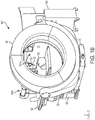
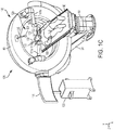
- FIGS. 1A-1C A system 100 for performing robotically-assisted surgery according to one embodiment is shown in FIGS. 1A-1C .
- FIGS. 1A and 1C are perspective views showing the first (i.e., front) side of the system 100 and FIG. 1B is a perspective view showing a second (i.e., rear) side of the system 100.
- the system 100 includes at least one robotic arm 101 that is movable with respect to a patient 103.
- the system 100 includes two robotic arms 101a, 101b that may be moved independently of one another. It will be understood that in other embodiments, the system 100 may include a single robotic arm or more than two robotic arms.
- the movements of the robotic arm(s) 101a, 101b may be controlled by a controller 105 (e.g., a computer including a memory and processor for executing software instructions) that may be coupled to the robotic arm(s) 101a, 101b via a wired or wireless link 107.
- the controller 105 for the robotic arms 101a, 101b is located in a workstation/mobile cart 109 that may include a display 111 and one or more user input devices 100 (e.g., touchscreen controller, keyboard, mouse, buttons, switches, etc.) to enable a user to control the operation of the system 100.
- user input devices 100 e.g., touchscreen controller, keyboard, mouse, buttons, switches, etc.
- each of the robotic arms 101a, 101b comprises a multi-joint arm that includes a plurality of linkages 113 connected by joints 115 having actuator(s) and optional encoder(s) to enable the linkages to bend, rotate and/or translate relative to one another in response to control signals from the control system 105.
- a first end 117 of the robotic arm 101a, 101b may be fixed to a structure 40 and a second end 119 of the arm may be freely movable with respect to the first end 117.
- An end effector 121 is attached to the second end 119 of the robotic arm 101a, 101b.
- the end effector 121 may be an invasive surgical tool, such as a needle, a cannula, a cutting or gripping instrument, an endoscope, etc., that may be inserted into the body of the patient.
- the end effector 121 of the robotic arm 101a, 101b may be a hollow tube or cannula that may receive an invasive surgical tool 122 (see FIG. 1C ), including without limitation a needle, a cannula, a tool for gripping or cutting, an electrode, an implant, a radiation source, a drug and an endoscope.
- the invasive surgical tool 122 may be inserted into the patient's body through the hollow tube or cannula by a surgeon.
- An end effector 121 comprising a hollow tube or cannula may be made of a radiolucent material, such as a carbon-fiber or thermoplastic material.
- the patient 103 which may be a human or animal patient, may be located on a suitable patient support 60, which may be a surgical table as shown in FIGS. 1A-1C .
- the patient support 60 in this embodiment is raised off the ground by a support column 50.
- the robotic arms 101a, 101b may be located partially or completely within the sterile surgical field, and thus may be covered by a surgical drape or other sterile barrier (not shown for clarity).
- the end effector 121 e.g., a hollow tube or cannula
- the end effector 121 may be a sterilized component that may be attached (e.g., snapped into) the end 119 of the robotic arm 101 over the drape.
- the end effector 121 may be a sterile, single-use (i.e., disposable) component that may be removed and discarded after use.
- the system 100 also includes an imaging device 125 that may be used to obtain diagnostic images of the patient 103.
- the imaging device 125 may be located in proximity to both the patient 103 and the at least one robotic arm 101a, 101b (e.g., within 10 meters, such as less than 5 meters, including 0-3 meters from the patient 103 and arm(s) 101a, 101b), and is preferably located within the same room (e.g., an operating room).
- the imaging device 125 includes a base 20 and a gantry 40 located above the base 20.
- the gantry 40 in this embodiment includes a substantially O-shaped housing (i.e., a ring) defining a bore 16.
- the gantry 40 includes one or more imaging components (not shown for clarity) located within the housing of the gantry 40 that are configured to obtain image data of at least a portion of an object (e.g., patient 103) positioned within the bore 16.
- the first end 117 of each of the robotic arms 101 a, 101b is attached to the imaging device 125.
- each of the robotic arms 101a, 101b are attached to a first (i.e., front) side 127 of the gantry 40, although it will be understood that the robotic arms 101a, 101b may be mounted at other portions of the imaging device 125 or system 100.
- the imaging device 125 may include one or more adaptors configured to receive a robotic arm 101 at one or more locations on the device 125.
- the adaptor(s) may be molded or affixed (e.g., using fasteners or adhesive) to an outer surface of the device 125.
- the first end 117 of a robotic arm 101 may be inserted into and secured by the adaptor.
- the robotic arm(s) 101 may be released from the adaptor and removed from the imaging device 125 for transport and/or storage.
- the robotic arms 101a, 101b may be stored on and/or transported by the cart 109.
- the imaging device 125 may be an x-ray computed tomography (CT) imaging device.
- CT computed tomography
- the imaging components within the gantry 40 may include an x-ray source and an x-ray detector.
- the x-ray source and optionally the detector may rotate within the gantry 40 around the bore 16 to obtain x-ray image data (e.g., raw x-ray projection data) of an object located within the bore 16.
- the collected image data may be processed using a suitable processor (e.g., computer) to perform a three-dimensional reconstruction of the object, which may be, for example, rendered on the display 111. Examples of x-ray CT imaging devices that may be used according to various embodiments are described in, for example, U.S. Patent No.
- the imaging device 125 may be an x-ray fluoroscopic imaging device, a magnetic resonance (MR) imaging device, a positron emission tomography (PET) imaging device, a single-photon emission computed tomography (SPECT), an ultrasound imaging device, etc.
- MR magnetic resonance
- PET positron emission tomography
- SPECT single-photon emission computed tomography
- ultrasound imaging device etc.
- the imaging system 125 may be configured to move with respect to the patient 103.
- the imaging system 125 e.g., the gantry 40
- the patient support 60 on which a patient 103 may be located is secured to the base 20 of the imaging system 125 by the column 50, and the gantry 40 may translate with respect to the base 20, the column 50 and the patient support 60.
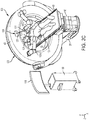
- FIGS. 2A-2C show the gantry 40 translated on the base 20 so that a portion of the patient 103 and patient support 60 are located within the bore 16 of the gantry 40.
- the column 50 is located on a first end of the base 20 and the patient support 60 attached to the column 50 is cantilevered over the base 20 so that the gantry 40 may translate over substantially the entire length of the patient support 60.
- the gantry 40 is supported by a gimbal 30 that includes a pair of arms 31, 33 that extend upwards from the base 20 and are connected to opposite sides of the gantry 40.
- the gimbal 30 may include bearing surfaces that travel on rails 23 on the base 20 to provide the translation motion of the gimbal 30 and gantry 40.
- a drive mechanism (not shown for clarity) may drive the translation of the gimbal 30 and gantry 40.
- An encoder or similar sensing device may determine the translation position of the gantry 40 on the base 20. In embodiments, the gantry 40 may tilt with respect to the gimbal 30.
- the patient support 60 and/or the column 50 may be translated as an alternative or in addition to translating the gantry 40 of the imaging system 125.
- the patient support 60 may be translated with respect to the column 50, or the entire column 50 and patient support 60 may be translated with respect to the base 20. In this way, the patient 103 may be moved into and out of the bore 16 of the gantry 40.
- the column 50 may be configured to raise and lower the height of the patient support 60 with respect to the base 20.
- the patient support 60 may also be rotatable with respect to the base 20, either by rotating the patient support 60 on the column 50 or by rotating the column 50 and patient support 60 with respect to the base 20.
- the system 100 may also include a motion tracking apparatus 129 for tracking the position of at least one of the robotic arm(s) 101a, 101b and the imaging system 125 in three-dimensional space.
- the tracking apparatus 129 may also track the position of the patient 103 as well as other objects, such as the patient support 50 and/or surgical tools 122 within the surgical area.
- Such systems may include a plurality of active or passive markers fixed to the object(s) to be tracked and a sensing device that detects radiation emitted by or reflected from the markers.
- a 3D model of the space may be constructed in software based on the signals detected by the sensing device.
- the motion tracking apparatus 129 is an optically-based motion tracking apparatus that includes an optical sensor (i.e. camera) 131 and one or more markers 133.
- the camera 131 is attached to the gantry 40 of the imaging device 125 and is oriented such that the camera 131 may look directly into the sterile surgical field.
- the camera 131 may be mounted to another portion of the imaging device 125 or to another component of the system 100, such as the patient support 60, or may be mounted to a separate support structure.
- An advantage of the configuration shown in FIGS. 1A-2C is that the camera 131 may look down directly into the surgical field without being blocked.
- the camera 131 may be mounted to the end of an arm 135 that may include actuator(s) for moving the camera 131 so that the surgical field is maintained within the camera's field of view.
- the camera 131 may swivel on the arm 135 and/or the arm 135 itself may pivot, bend, extend and/or contract to maintain the surgical field within the field of view of the camera 131.
- the markers 133 may comprise any active or passive marker that may be detected by the camera 131.
- the markers 133 may be fixed to various objects to be tracked, such as the end effectors 121 of the robotic arms 101a, 101b, as shown in FIG. 1C .
- One or more markers 133 may also be attached to surgical tools 122 to enable the position and orientation of the various surgical tools 122 within the surgical field to be tracked in real time during a surgical procedure.
- One or more markers 133 may also be attached to other objects, such as the patient 103, the patient support 60 and/or the imaging device 125.
- the markers 133 may be moiré pattern markers that may provide measurement data for position and orientation using a single camera 131 using Moiré Phase Tracking (MPT) technology.
- MPT Moiré Phase Tracking
- Each marker 133 may also include a unique identifier or code that may enable different objects within the camera's field of view to be uniquely identified and tracked.
- An example of an MPT-based tracking system is available from Metria Innovation Inc.
- FIG. 3 is a system block diagram that schematically illustrates various components of the system 100 according to one embodiment.
- a first controller 105 may control the operation of one or more robotic arms 101a, 101b.
- the first controller 105 may receive feedback data (indicated by arrow 201) from the robotic arm(s) 101a, 101b regarding the status and operation of the arms 101a, 101b.
- the feedback data may include sensor (e.g., encoder) data that may be used to determine the position and orientation of each of the joints 115 of the robotic arms 101a, 101b.
- the first controller 105 may send control signals (indicated by arrow 203) to the robotic arm(s) 101a, 101b to control the movements of the arms 101a, 101b.
- the system 100 may also include a second controller 205 for controlling the operation of the imaging device 125.
- the second controller 205 may receive feedback data (indicated by arrow 207) regarding the status and operation of the imaging device 125.
- the feedback data may include information as to the position and orientation of the imaging device 125, such as the position (translation or tilt) of the gantry 40 and/or the position of the patient support 60.
- the second controller 205 may also send control signals (indicated by arrow 209) to various components of the imaging device 125 to control the operation of the imaging device 125, including controlling the imaging device 125 to obtain image data 211 (e.g., a three-dimensional CT reconstruction) of an object located within the bore 16 of the gantry 40.
- the image data 211 may be displayed on a display 111.
- the system 100 may also include a third controller 213 for controlling the operation of the motion tracking apparatus 129.
- the third controller 213 may receive data sensed by the camera 131 (indicated by arrow 215) and based on this data may determine position and/or orientation data for each of the markers 133 within the field of view of the camera 131. Based on the determined position and/or orientation of the markers 133, a three-dimensional model 219 of various objects within the surgical space (e.g., the patient 103, surgical tool(s) 122, the end effector(s) 121 of the robotic arm(s) 101a, 101b, the imaging device 125, etc.) may be generated.
- the third controller 213 may also send control signals (indicated by arrow 217) to the camera 131 to control the operation of the camera 131, such as by adjusting the camera's field of view.
- the first, second and third controllers 105, 205, 213 may communicate and share various data with one another, as indicated by arrows 221, 223 and 225.
- the sharing of data including positional data enables the controllers to operate in a common coordinate system.
- the image data 211 of the patient 103 obtained by the imaging device 125 may be registered to the position data obtained by the motion tracking apparatus 129, as is known in the field of surgical navigation systems.
- the position of one or more objects tracked by the motion tracking apparatus 129 may be shown on the display 111, such as overlaying the display of image data 211 from the imaging device 125.
- the first controller 105 may determine the position of the robotic arm(s) 101a, 101b with respect to the rest of the system 100 based on position data from the motion tracking apparatus 129 and/or the imaging device 125.
- each of the controllers 105, 205, 213 may comprise separate computing devices, each including a memory and processor for performing the various functions described herein.
- the separate computing devices may communicate with one another via a suitable data link (e.g., Ethernet).
- a suitable data link e.g., Ethernet
- two or more of the controllers 105, 205, 213 may be integrated in a single computing device.
- a system 100 as described above may be used for performing surgical procedures on a patient 103, which may be a human or animal patient.
- the patient 103 may be provided on a patient support 60 (e.g., a surgical table), and the imaging device 125 may be used to obtain images of the patient 103, such as a CT scan of a particular region of the patient's anatomy.
- This may include moving the gantry 40 of the imaging device 125 (e.g., translating the gantry 40 on the base 20) so that a region of interest of the patient 103 is located within the bore 16 of the gantry 40 and operating the imaging components (e.g., x-ray source and detector) to obtain image data of the patient 103.
- the patient 103 may be moved into the bore 16, such as by translating the patient support 60 into the bore 16 of the gantry 40.
- the image data obtained by the imaging device 125 may be displayed on a display, such as the display 111 on the mobile cart 109 shown in FIGS. 1A-2C .
- a surgeon or other clinician may interact with the image data shown in the display 111 using a suitable user interface/input device 110 (e.g., keyboard, mouse, touchpad, trackball, touchscreen, etc.).
- the clinician may be able to modify the image data displayed on the screen of the display 111, such as by zooming in or out of a particular region, selecting or changing the particular projection angle(s) or slices in the case of a three-dimensional tomographic reconstruction.
- a surgeon/clinician may also select particular points on the displayed image using an input device.
- FIG. 4 shows a display 111 that displays an image 401 (e.g., a cross-sectional slice) of a region of interest of a patient 103 obtained using an imaging device 125.
- the surgeon/clinician may identify and select at least one target point 403 in the displayed image 401.
- the target point 403 may represent an end point for the insertion of a particular surgical tool 122 into the patient's body during a surgical procedure.
- the surgeon/clinician may also identify and select at least one entrance point 405 on the displayed image 401.
- the entrance point 405 may represent a point on the exterior of the patient's body (e.g., the skin) through which the surgeon will insert the particular surgical tool 122.
- the target point 403 and corresponding entrance point 405 thus define a unique trajectory 407 through the body of the patient 103, as schematically illustrated by the dashed line in FIG. 4 .
- the surgeon may select the entrance point 405 and the trajectory 407 within the patient's body in order to facilitate the insertion of the surgical tool 122 to the target point 403 while minimizing damage to other tissue or organs of the patient 103.
- the trajectory 407 may also be extended outside of the patient's body to define a unique vector 409 in three-dimensional space extending from the selected entrance point 405, as indicated by the dashed-dotted line in FIG. 4 .
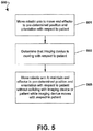
- FIG. 5 is a process flow diagram that illustrates a method 500 for operating a robotic arm 101 to perform robotically-assisted surgery according to one embodiment.
- the method 500 may be performed using the system 100 described above with reference to FIGS. 1A-4 .
- the system 100 may include at least one robotic arm 101a, 101b having an end effector 121.
- the end effector 121 may comprise a hollow tube or cannula, as described above.
- Each of the robotic arms 101a, 101b may be moveable with respect to a patient 103 and an imaging device 125, where at least a portion of the imaging device 125, such as a gantry 40, is moveable with respect to the patient 103 to obtain imaging data of the patient 103.
- the system 100 may also include a controller 105 for controlling the movements of the at least one robotic arm 101a, 101b.
- the controller 105 may control the at least one robotic arm 101 to move the end effector 121 of the robotic arm 101 to a pre-determined position and orientation with respect to the patient 103.
- the pre-determined position and orientation may be based on imaging data obtained by the imaging system 125.
- the imaging data may be used to determine a unique vector 409 in three-dimensional space corresponding to a desired insertion trajectory 407 for a surgical tool, as described above with reference to FIG. 4 .
- the controller 105 of the at least one robotic arm 101a, 101b may translate this vector 409 into a coordinate system used for controlling the position and movement of the robotic arm 101a, 101b based on positional information received from the imaging device 125 and/or from a motion tracking apparatus 129, as described above with reference to FIG. 3 .
- the controller 105 may move the at least one first robotic arm 101a, 101b so that the end effector 121 of the robotic arm 101a, 101b is oriented along a pre-defined vector 409. For example, as shown in FIG. 1A , the end effector 121 of a first robotic arm 101a is oriented along a first vector 409a.
- the end effector 121 of a second robotic arm 101b is oriented along a second vector 409b.
- Each of the end effectors 121 may be positioned adjacent to a desired entrance point 405 for a surgical tool. A surgeon may then perform an invasive surgical procedure, which may include inserting one or more surgical tools through the end effectors 121 and into the body of the patient 103. The position and orientation of the end effectors 121 may ensure that the surgical tools 121 follow the desired trajectory 407 (see FIG. 4 ) through the patient's body to reach the target area.
- a motion tracking apparatus 129 such as described above may be configured to track the at least one robotic arm 101a, 101b to ensure that the end effector(s) 121 maintain the pre-determined position and orientation with respect to the patient 103. If an end effector 121 moves from the pre-determined position and orientation (e.g., due to the robotic arm being accidentally bumped), the motion tracking apparatus 129 may detect this movement and alert the surgeon or other clinician. Alternately or in addition, the motion tracking apparatus 129 may send a message to the controller 105 of the at least one robotic arm 101a, 101b indicating a detected deviation from the pre-determined position and orientation of the end effector 121. The controller 105 may then move the robotic arm 101a, 101b to compensate for the detected deviation.
- the motion tracking apparatus 129 may also track the patient 103 (e.g., where a plurality of markers 133 are placed on the patient 103) to determine whether the patient 103 has moved relative to the end effector 121.
- the motion tracking apparatus 129 may notify the surgeon when the patient 103 moves by more than a pre-determined amount.
- the motion tracking apparatus 129 may send message(s) to the controller 105 of the robotic arms(s) 101a, 101b regarding detected movements of the patient 103. Such movements may include, for example, motion of the patient 103 corresponding to the patient's breathing.
- the controller 105 may move the robotic arm(s) 101a, 101b to compensate for any such movement (e.g., to maintain the end effector 121 in the same position and orientation with respect to the selected entrance point 405 on the patient's body).
- the motion tracking apparatus 129 may also be used to track a variety of objects, including surgical tools 122, within the surgical area.
- various surgical tools 122 may be provided with markers 122 that enable the motion tracking system 129 to identify the tools and continually track their movements in three-dimensional space.
- the motion tracking system 129 may use the detected position of the marker(s) 133 and a known geometry of the tool 122 to determine the depth of insertion of the tool 122 into the body. This may be displayed on the display 111 of the system 100 (e.g., overlaying the image data previously obtained from the imaging device 125) and may aid the surgeon in determining whether the surgical tool 122 has been inserted to the desired depth in the patient's body.
- the controller 105 may determine that at least a portion of the imaging device 125 is moving with respect to the patient 103. For example, after obtaining imaging data of the patient 103, the gantry 40 of the imaging device 125 may be translated away from the surgical area as shown in FIGS. 1A-1C to provide easier access to the surgical area for performing a surgical procedure. The robotic arm(s) 101a, 101b may then be moved to a first position as shown in FIGS. 1A-1C , with the end effector(s) 121 arranged in a pre-determined position and orientation with respect to the patient 103.
- the surgeon may wish to obtain additional image data of the patient 103 (e.g., to confirm the location of a surgical tool 122 within the patient 103), and the gantry 40 may be translated back over the surgical area such as shown in FIGS. 2A-2C to perform an updated imaging scan.
- the robotic arm(s) 101a, and 101b may be moved into position on the patient 103 as shown in FIGS. 1A-1C while the gantry 40 is still located over the surgical area.
- the gantry 40 may then be moved (e.g., translated) out of the surgical area as shown in FIGS. 2A-2C before performing the surgical procedure.
- the controller 105 may determine that at least a portion of the imaging device (e.g., the gantry 40) is moving with respect to the patient 103 based on a signal that may be received, for example, from the imaging device 125, the motion tracking system 129 and/or from a user via a user input mechanism.
- the controller 105 may control the at least one robotic arm 101a, 101b to move a first portion of the at least one robotic arm 101a, 101b while the imaging device 125 moves with respect to the patient 103 while maintaining the end effector 121 of the arm in the pre-determined position and orientation (e.g., vector 409) with respect to the patient 103.
- the pre-determined position and orientation e.g., vector 409
- the controller 105 may control the movements of the arm 101 such that as the first end 117 of the arm moves towards or away from the patient 103, the end effector 121 maintains its original position and orientation with respect to the patient 103.
- the controller 105 may control the movement of the first portion of the arm 101a, 101b such that the arm 101a, 101b does not collide with either the imaging device 125 or the patient 103 during the movement of the arm.
- the imaging device 125 and robotic arms 101a, 101b move from the position as shown in FIGS. 1A-1C to the position as shown in FIGS. 2A-2C , at least a portion of the arms 101a, 101b including the end effectors 121 are located inside the bore 16 of the gantry 40.
- the controller 105 may control the movement of each of the arms 101a, 101b so that as the gantry 40 advances towards the patient, none of the joints 115 of the arms 101a, 101b collide with the side wall or inner diameter of the ring or with the patient 103.
- the controller 105 may control the movement(s) of the arm(s) 101a, 101b in accordance with a motion planning algorithm that utilizes inverse kinematics to determine the joint parameters of the robotic arm that maintain the position and orientation of the end effector 121 while avoiding collisions with the imaging device 125 and the patient 103.
- the controller 105 may determine the position of each of the robotic arms 101a, 101b in relation to the gantry 40 based on position data received from the imaging device 125 (e.g., indicating the translation and/or tilt position of the gantry 40 with respect to the base 20). Alternately or in addition, the controller 105 may utilize position information received from the motion tracking apparatus 125. As discussed above, the motion tracking system 129 may be used to construct a three-dimensional model (e.g., a CAD model) of the various objects being tracked by the motion tracking apparatus 129. The sharing of data between the robotic system, the imaging device and the motion tracking apparatus may enable these systems to operate in a common coordinate system.
- position data received from the imaging device 125 e.g., indicating the translation and/or tilt position of the gantry 40 with respect to the base 20.
- the controller 105 may utilize position information received from the motion tracking apparatus 125.
- the motion tracking system 129 may be used to construct a three-dimensional model (e.g., a
- the position of the patient 103 may be defined using a freehand technique.
- the surgeon or other clinician may use the second (i.e., distal) end 119 of a robotic arm 101 to manually trace across the external surface of the patient 103, such as around the surgical area.
- This may be used to define a three-dimensional boundary surface in the common coordinate system into which no portion of the at least one robotic arm 101a, 101b may enter.
- This technique may also be used to define boundary surfaces corresponding to other objects and components of the system 100 proximate to the surgical area, such as the patient support 60 or portions of the imaging system 125.
- the motion tracking apparatus 129 may be used to define the boundary surface corresponding to the patient 103, such where a plurality of markers 133 are placed in different locations on the patient 103 proximate to the surgical area and are tracked by the camera 131.
- the positions of the markers 133 tracked by the motion tracking apparatus 129 may be used to define a three-dimensional boundary surface into which the robotic arm 101a, 101b may not enter.
- the controller 105 of the at least one robotic arm 101a, 101b may determine that it is not possible to move a robotic arm without either changing the position or orientation of the end effector 121 with respect to the patient 103, or some part of the arm colliding with the imaging device 125 or the patient 103. For example, a translation of the gantry 40 may result in the arm 101 being extended beyond its maximum length. In other cases, the controller 105 may determine that no set of joint movements are possible to avoid collisions while maintaining the end effector in a fixed position and orientation. In such a case, the controller 105 may issue an alert that may be perceived by the surgeon or other clinician, and may preferably also send a signal to the imaging device 125 to stop the motion of the gantry 40.
- the camera 131 may also move to maintain the surgical area within the field-of-view of the camera 131.
- the camera 131 may include an actuator (e.g., a DC motor-based actuator) that causes the camera 131 to pivot on the arm 135 to keep the camera 131 pointed down into the surgical area while the camera 131 moves with the gantry 40.
- an actuator e.g., a DC motor-based actuator
- This may enable the motion tracking apparatus 129 to continually track the position of objects within the surgical area as the gantry 40 and robotic arms 101a, 101b move.
- the motion tracking apparatus 129 may provide a redundant safety feature in that if the motion tracking apparatus 129 detects a movement of an end effector 121 from the pre-determined position and orientation with respect to the patient 103, the surgeon or other clinicians may be promptly notified.
- the motion tracking apparatus 129 may send a message to the imaging system 125 and the controller 105 of the robotic arm(s) to stop all motion of the system 100.
- the imaging device 125 may be operated to obtain imaging data of the patient 103 (e.g., a CT scan of at least a portion of the patient 103).
- the system 100 may therefore be configured as shown in FIGS. 2A-2C , with the gantry 40 moved over the surgical area and at least a portion of the robotic arms 101a, 101b including the end effectors 121 are located within the bore 16.
- the end effectors 121 may comprise a radiolucent material so as not to block x-rays.
- the updated image data may be shown on the display 111, and may enable the surgeon to confirm the location of a surgical tool 122 inserted into the patient 103.
- the gantry 40 may be moved out of the surgical area, such as by translating the gantry 40 to the position as shown in FIGS. 1A-1C .
- the controller 105 of the robotic arms 101a, 101b may again control the robotic arms to maintain the pre-determined position and orientation of the end effectors 121 with respect to the patient 103 while the gantry 40 translates with respect to the patient.
- FIGS. 6A-6C and 7A-7C An alternative embodiment of a system 100 for robotically-assisted surgery is shown in FIGS. 6A-6C and 7A-7C .
- the system 100 in this embodiment is substantially identical to the system 100 described above with reference to FIGS. 1A-2C .
- This embodiment differs from the embodiments described above in that there is a single robotic arm 101 (rather than the pair of arms 101a, 101b shown in FIGS. 1A-2C ).
- the robotic arm 101a and the camera 131 for the motion tracking system 129 are attached to the gantry 40 of the imaging device 125.
- the robotic arm 101 and the camera 131 are attached to the side of the gantry that faces away from the patient 103.
- the configuration as shown in FIGS. 6A-6C and 7A-7C may be advantageously used, for example, for a cranial surgical procedure (e.g., neurosurgery, deep brain stimulation, insertion of an external ventricular drain, etc.).
- a cranial surgical procedure e.g., neurosurgery, deep brain stimulation, insertion of an external ventricular drain, etc.
- the head 601 of the patient 103 may be stabilized at one end of the patient support 60.
- the head 601 may be located within the bore 16 of the gantry 40 of the imaging device 125 for obtaining pre-operative or intra-operative image data.
- the robotic arm 101 may be moved to a position such that the end effector 121 is in a pre-determined position and orientation with respect to the patient 103, as described above.
- the gantry 40 may be moved down along the length of the patient's body to provide easier access to the surgical area, as shown in FIGS. 7A-7C .
- the controller 105 of the robotic arm 101 may control the movements of robotic arm 101 such that the end effector 121 is maintained in the pre-determined position and orientation with respect to the patient 103 while the gantry 40 moves. As shown in FIGS. 7A-7C , this may include a stretching out or unfolding of the arm. Similarly, as the gantry 40 translates towards the head 601 of the patient 103 the joints of the arm 101 may be folded up as shown in FIGS. 6A-6C .
- the controller 105 of the robotic arm 101 may use inverse kinematics to ensure that the position and orientation of the end effector 121 with respect to the patient 103 is maintained without any portion of the arm 101 colliding with either the imaging device 125 or the patient 103.
- the camera 131 of the motion tracking apparatus 129 and/or the arm 135 to which the camera 131 is attached may move in response to the movement of the gantry 40 to maintain the surgical area within the field-of-view of the camera 131.
- FIGS. 8A-8D and 9A-9B Yet another embodiment of a system 100 for robotically-assisted surgery is shown in FIGS. 8A-8D and 9A-9B .
- the system 100 in this embodiment is substantially identical to the system 100 as previously described.
- This embodiment differs from those described above in that a pair of robotic arms 101a, 101b are attached to the patient support 60 rather than to the gantry 40 of the imaging device 125.
- the camera 131 for the motion tracking system 129 is attached to the gantry 40 of the imaging device 125.
- the robotic arms 101a, 101b may be attached at any suitable location on the patient support 60, such as on surgical rails 801 that extend along the sides of the patient support 60.
- an adaptor 803 may be secured to a surgical rail 801, and the robotic arm may be snapped into or otherwise secured to the adaptor.
- FIGS. 8A-8D and 9A-9B show the operation of the embodiment shown in FIGS. 8A-8D and 9A-9B translated to the previous embodiments.
- FIGS. 8A-8D show the gantry 40 translated over the surgical area
- FIGS. 9A-9B show the gantry 40 translated away from the surgical area in order to allow the surgeon access to the surgical area.
- the robotic arms 101a, 101b are attached proximate to the distal end of the patient support 60 (i.e., opposite the support column 50).
- the robotic arms 101a, 101b extend into or through the bore 16 of the gantry 40 in order to move the end effectors 121 to the pre-determined position and orientation with respect to the patient 103.
- a difference between the embodiment shown in FIGS. 8A-8D and the previous embodiments is that because the robotic arms 101a, 101b are attached to the patient support 60 rather than the gantry 40, the robotic arms 101a, 101b may not need to move with respect to the patient 103 once the end effectors 121 are moved to the predetermined position and orientation.
- the controller 105 of the robotic arms 101a, 101b may move the end effectors 121 to the pre-determined position and orientation such as shown in FIGS. 8A-8D and 9A-9B without colliding the arms 101a, 101b with either the imaging system 125 or the patient 103.
- the arms 101a, 101b may be moved to a configuration such that they will not collide with the gantry 40 as the gantry 40 moves (e.g., translates) with respect to the patient 103, such as between the positions shown in FIGS. 8A-8D and 9A-9B , respectively.
- the arms 101a, 101b may be moved to an initial configuration with the end effectors 121 in the pre-determined position and orientation with respect to the patient 103, and a portion of the arm(s) 101a, 101b may be moved to avoid colliding with the gantry 40 and the patient 103 while maintaining the position and orientation of the end effectors 121 when the gantry 40 moves with respect to the patient.
- the camera 121 of the motion tracking apparatus 129 is attached to the gantry 40 by arm 135. As shown in FIGS. 8A-8D and 9A-9B , the camera 131 and/or the arm 135 may move in response to the movement of the gantry 40 to maintain the surgical area within the field-of-view of the camera 131.
- FIGS. 10A-10C and 11A-11C Yet another embodiment of a system 100 for robotically-assisted surgery is shown in FIGS. 10A-10C and 11A-11C .
- the patient support 60 is configured for a patient 103 in a seated position.
- a robotic arm 101 and a camera 131 for the motion tracking apparatus 129 are both mounted to the patient support 60.
- the robotic arm 101 and camera 131 are attached to surgical rails 801 extending along opposite sides of the patient support 60.
- FIGS. 10A-10C show the gantry 40 of the imaging device 125 translated away from the patient 103
- FIGS. 11A-11C show the gantry 40 translated to the patient 103 such that the surgical area is located within the bore 16.
- the gantry 40 is tilted with respect to the gimbal 30 in this embodiment.
- the operation of the system 100 in the embodiment shown in FIGS. 10A-10C and 11A-11B may be substantially identical to the embodiments described above.
- the robotic arm 101 may be moved to a position such that the end effector 121 is in a pre-determined position and orientation with respect to the patient 103, as described above.
- the camera 131 and arm 135 may be positioned such that the camera 131 is looking into the surgical area. If an imaging scan is desired, the gantry 40 which is tilted on the gimbal 30 may be translated towards the patient 103, such as shown in FIGS. 11A-11C .
- the controller 105 of the robotic arm 101 may use inverse kinematics to move the robotic arm 101 to maintain the position and orientation of the end effector 121 with respect to the patient 103 without any portion of the arm 101 colliding with either the imaging device 125 or the patient 103.
- the patient support 60 may be rotatable with respect to the imaging device 125, such as shown in FIGS. 12A-12B , which may provide the surgeon with additional space for performing a surgical procedure.
- FIGS. 12A-12B show the patient support 60 rotated 90° with respect to the imaging device 125.
- the patient support 60 may be rotated back to the position as shown in FIGS. 10A-10C , and the gantry 40 may be translated over the patient 103 to obtain the imaging scan, as shown in FIGS. 11A-11C .
- the robotic arm 101 is mounted to the patient support 60 and thus moves with the patient support 60 as it rotates.
- the robotic arm 101 may be mounted to another structure, such as the imaging device 125 or to a separate support structure, and the controller 105 of the robotic arm 101 may be configured to move the robotic arm 101 to maintain the end effector 121 in the pre-determined position and orientation with respect to the patient 103 as the patient support 60 rotates.
- the robotic arm 101 may be attached anywhere on the system 100, such as the on the gantry 40, the patient support 60, the support column 50, the base 20 or the gimbal 30.
- Mounting a robotic arm on the gimbal 30 may enable the robotic arm 101 to remain in close proximity to the gantry 40 and easily extend into the bore 16 of the gantry 40 without the weight of the robotic arm 101 being distributed onto the gantry 40 itself, which may be weight balanced.
- attaching the robotic arm 101 to the gimbal 30 may enable the gantry 40 to be tilted with respect to the patient without also tilting the first end 117 of the robotic arm 101 with respect to the patient.
- One or more robotic arms 101 may be mounted directly to the gimbal 30 (e.g., proximate to the end(s) of one or both of the arms 31, 33 that attach to opposing sides of the gantry 40).
- a plate or other support member may be attached to and extend from an arm 31, 33 of the gimbal 30, and the robotic arm 101 may be mounted to the plate/support member.
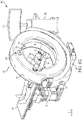
- a support member 1300 may extend from the gimbal 30 (e.g., from the end of an arm 31, 33 of the gimbal 30) and at least one robotic arm 101 may be mounted to the support member 1300.
- the support member 1300 may extend at least partially around an outer circumference of the gantry 40.
- the support member 1300 comprises a curved rail that extends around the outer circumference of the gantry 40.
- the support member 1300 forms a semicircular arc that extends between the ends of the respective arms 31 and 33 of the gimbal 30.
- the semicircular support member 1300 may be concentric with the outer circumference of the gantry 40.
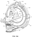
- a bracket mechanism 1301 may be located on the support member 1300 and may include a mounting surface 1303 for mounting the first end 117 of the robotic arm 101 to the bracket mechanism 1301. As shown in FIGS. 13A-13D , the mounting surface 1303 may project from the side of the support member and may be upwardly angled as shown in FIGS. 13A-13D . This may provide additional clearance for the "tilt" motion of the gantry 40 relative to the gimbal 30.
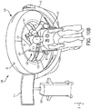
- the bracket mechanism 1301 and the robotic arm 101 attached thereto may be moved to different positions along the length of support member 1300 (e.g., any arbitrary position between the ends of the arms 31, 33 of the gimbal 30) and may be fixed in place at a particular desired position along the length of the support member 1300.
- FIGS. 13C and 13D are perspective and front views of the system 100 illustrating the bracket mechanism 1301 and the robotic arm 101 in a first position and a second position (indicated by phantom) on the support member 1300.
- the bracket mechanism 1301 may be moved manually (e.g., positioned by an operator at a particular location along the length of the support member 1301 and then clamped or otherwise fastened in place).
- the bracket mechanism 1301 may be automatically driven to different positions using a suitable drive mechanism (e.g., a motorized belt drive, friction wheel, gear tooth assembly, cable-pulley system, etc., not shown in FIGS. 13A-13D ).
- the drive mechanism may be located on the bracket mechanism 1301, the support member 1300 and/or the gimbal 30, for example.
- An encoder mechanism may be utilized to indicate the position of the bracket mechanism 1301 and the first end 117 of the robotic arm 101 on the support member 1300.
- FIGS. 13A-13D illustrates one robotic arm 101 mounted to the support member 1300, it will be understood that more than one robotic arm may be mounted to the support member 1300 via respective bracket mechanisms 1301.
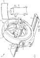
- FIG. 13A-13D also illustrates a motion tracking apparatus 1305 which is similar to the motion tracking apparatus described above.
- the motion tracking apparatus 1305 includes a stereoscopic optical sensor device 1304 that includes two or more IR cameras 1306, 1308 attached to the gantry 40 of the imaging device.
- the optical sensor device 1304 may include one or more IR sources (e.g., diode ring(s)) that direct IR radiation into the surgical field, where the IR radiation may be reflected by markers and received by the cameras 1306, 1308.
- a plurality of markers 1307 may be attached to the patient to form a "reference arc" that enables the cameras 1306, 1308 to track the patient.
- the optical sensor device 1305 may include a two-axis robotic system to enable the cameras 1306, 1308 to tilt and pan (i.e., rotate up-and-down and side-to-side) such that the reference arc on the patient may be maintained in the center of the cameras' field of view.
- a second set of markers 1309 may be attached to the second end 119 of the robotic arm 101 or to the end effector 121 to enable the tracking system to track the end effector 121.
- the second set of markers 1309 preferably comprises four or more non-coplanar markers in a fixed, known geometric relationship with each other and to the end effector 121, which enables both the position (x, y, z) and the orientation (yaw, pitch, roll) of the end effector 121 to be fully resolved. Similar sets of markers may be provided on any instruments or other objects brought into the surgical field to allow these objects to be tracked.
- the optical sensor device 1304 is mounted to the first (i.e., front) side 127 of the gantry 40 via a second support member 1311.
- the second support member 1311 may be a curved (e.g., semicircular) rail that may be attached to an upper portion of the gantry 40 to enable the cameras 1306, 1308 to look down into the surgical field.
- the optical sensor device 1304 may be movable to different positions along the second support member 1311, either manually or using a drive system.
- This may provide flexibility so that the robotic arm 101 may be translated to any location on support member 1300 while the optical sensor device 1304 may be translated to one side or the other of the robotic arm axis so that the cameras 1306, 1308 may remain pointed down into the surgical field without being occluded by the end of the robotic arm 101.
- Other motion tracking apparatuses such as the apparatus 129 described above with reference to FIGS. 1A-12B , could be utilized in the system of FIGS. 13A-13D .
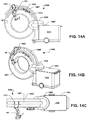
- FIGS. 14A-14C illustrate an alternative embodiment of a system 100 for performing robotically-assisted surgery that includes at least one robotic arm 101 mounted to an imaging system 1400.
- the imaging system 1400 includes an O-shaped imaging gantry 1401 that is mounted to a support structure 1403 in a cantilevered fashion.
- the imaging system 1400 may be an x-ray imaging system that may be used to obtain 2D fluoroscopic images and/or 3D tomographic images of an object located within the bore 16 of the gantry.
- At least one of an x-ray source and an x-ray detector may rotate around the interior of the gantry 1401 to obtain images of an object within the bore 16 from different projection angles.
- the support structure 1403 may comprise a mobile cart 1406 that is attached to one side of the gantry 1401 via an attachment mechanism 1405.
- the attachment mechanism 1405 may include one or more motorized systems that enable the gantry 1401 to translate and/or rotate with respect to at least a portion of the cart 1406.
- the gantry 1401 may be raised or lowered relative to the cart 1406 and/or may be translated over a limited range-of-motion along the z-axis (i.e., into and out of the page in FIG. 14A ) relative to the cart 1406.
- the gantry 1401 may be rotated with respect to the cart 1406 along one or more axis.
- the gantry 1401 may be tilted with respect to the cart 1406 about a horizontal axis extending through the attachment point between the gantry 1401 and cart 1406 and/or may have a "wag" rotation about a vertical axis with respect to the cart 1406.
- One or more robotic arms 101 may be attached anywhere on the imaging system 1400 of FIGS. 14A-14C , such as the on the gantry 1401, the cart 1406 or the attachment mechanism 1405.
- the robotic arm 101 is attached to a support member 1407 which may be similar to the support member 1300 described above with reference to FIGS. 13A-13D .
- the support member 1407 extends from the attachment mechanism 1405, although the support member 1407 may extend from any portion of the cart 1406.
- the support member 1407 in this embodiment is a semicircular segment that extends concentrically over an upper portion of the gantry 1401.
- the support member 1407 and the robotic arm 101 secured thereto may translate with the translation of the gantry 1401 along at least one axis (e.g., up and down translation) relative to the cart 1406.
- the gantry 1401 may be able to rotate (e.g., tilt) with respect to the cart 1406 without the support member 1407 and robotic arm 101 also rotating.
- the robotic arm 101 may be attached to the support member 1407 using a bracket mechanism 1301 as described above.
- the bracket mechanism 1301 and robotic arm may be moved to any arbitrary position along the length of the support member 1407.
- the system may include a tracking system comprising an optical sensor device 1304 mounted to a side of the gantry 1401 via a second support member 1313, as is described above with reference to FIGS. 13A-13D .
- the optical sensor device 1304 may be moveable to different positions along the length of the second support member 1313, as described above.
- Other motion tracking apparatuses such as the apparatus 129 described above with reference to FIGS. 1A-12B , could be utilized in the system of FIGS. 14A-14C .
- FIGS. 15A-15D illustrate another alternative embodiment of a system 100 for performing robotically-assisted surgery that includes at least one robotic arm 101 mounted to an imaging system 1500.
- the imaging system 1500 is a C-arm device that includes an x-ray source 1501 and a detector 1503 connected to one another by a C-shaped connecting member 1505.
- the C-shaped connecting member 1505 is coupled to a support structure 1507, which in this embodiment comprises a mobile cart 1509.
- An attachment mechanism 1511 attaches the C-shaped connecting member 1505 to the cart 1509 such that the attachment mechanism 1511 together with the source 1501, detector 1503 and C-shaped connecting member 1505 may be rotated in a first direction (i.e., into and out of the page in FIG.
- the source 1501, detector 1503 and C-shaped connecting member 1505 may also rotate in a second direction (i.e., within the plane of the page in FIG. 15A ) relative to the attachment mechanism 1511 and the cart 1509.
- the cart 1509 may be a mobile cart and may be used to move the entire imaging system 1500 to a desired position and orientation.
- the source 1501 and detector 1503 may be used to obtain x-ray images, such as 2D fluoroscopic images, of an object positioned between the source 1501 and detector 1503 from a variety of different projection angles.
- One or more robotic arms 101 may be attached anywhere on the imaging system 1500 of FIGS. 15A-15D , such as the on the cart 1509, the attachment mechanism 1511 or the C-shaped connecting member 1505.
- the robotic arm 101 is attached to a support member 1513 which may be similar to the support members 1300 and 1407 described above with reference to FIGS. 13A-13D and 14A-14C .
- the support member 1513 extends from the cart 1509.
- the support member 1513 in this embodiment is a curved (e.g., semicircular) segment that extends from the cart 1509 at least partially above the source 1501, detector 1503 and the C-shaped connecting member 1505.
- the support member 1513 may be concentric with the C-shaped connecting member 1505.
- the support member 1513 may be located such that the source 1501 and detector 1503 may freely rotate about one or more axes without contacting the support member 1513.
- the robotic arm 101 may be attached to the support member 1513 using a bracket mechanism 1301 as described above.
- the bracket mechanism 1301 and robotic arm 101 may be moved to any arbitrary position along the length of the support member 1513.
- the system may include a tracking system comprising an optical sensor device 1304 mounted to a side of the gantry 1401 via a second support member 1515.
- the second support member 1515 may be a second curved (e.g., semicircular) segment that extends from the cart 1509 at least partially above the source 1501, detector 1503 and the C-shaped connecting member 1505.
- the second support member 1515 may extend parallel to support member 1513, as shown in FIGS. 15A-15C .
- the second support member 1515 extends for a shorter length than support member 1513, although it will be understood that the second support member 1515 may extend for the same or a greater length than support member 1513.
- the optical sensor device 1304 may be moveable to different positions along the length of the second support member 1515, as described above. Alternately, both the robotic arm 101 and the optical sensor device 1304 may be mounted to the same support member (e.g., support member 1513). Also, other motion tracking apparatuses, such as the apparatus 129 described above with reference to FIGS. 1A-12B , could be utilized in the system of FIGS. 15A-15D .
- FIG. 16 is a system block diagram of a computing device useful to perform functions of a processing control unit, such as controllers 105, 205 and 213 described above. While the computing device 1600 is illustrated as a laptop computer, a computing device providing the functional capabilities of the computer device 1600 may be implemented as a workstation computer, an embedded computer, a desktop computer or a handheld computer (e.g., tablet, a smartphone, etc.).
- a typical computing device 1600 may include a processor 1601 coupled to an electronic display 1604, a speaker 1606 and a memory 1602, which may be a volatile memory as well as a nonvolatile memory (e.g., a disk drive).
- the computing device 1600 may also include a floppy disc drive, compact disc (CD) or DVD disc drive coupled to the processor 1601.
- the computing device 1600 may include an antenna 1610, a multimedia receiver 1612, a transceiver 1618 and/or communications circuitry coupled to the processor 1601 for sending and receiving electromagnetic radiation, connecting to a wireless data link, and receiving data.
- the computing device 1600 may include network access ports 1624 coupled to the processor 1601 for establishing data connections with a network (e.g., LAN coupled to a service provider network, etc.).
- a laptop computer or desktop computer 1600 typically also includes a keyboard 1614 and a mouse pad 1616 for receiving user inputs.
- DSP digital signal processor
- ASIC application specific integrated circuit
- FPGA field programmable gate array
- a general-purpose processor may be a microprocessor, but, in the alternative, the processor may be any conventional processor, controller, microcontroller, or state machine.
- a processor may also be implemented as a combination of computing devices, e.g., a combination of a DSP and a microprocessor, a plurality of microprocessors, one or more microprocessors in conjunction with a DSP core, or any other such configuration. Alternatively, some steps or methods may be performed by circuitry that is specific to a given function.
- the functions described may be implemented in hardware, software, firmware, or any combination thereof. If implemented in software, the functions may be stored on as one or more instructions or code on a non-transitory computer-readable medium.
- the steps of a method or algorithm disclosed herein may be embodied in a processor-executable software module executed which may reside on a non-transitory computer-readable medium.
- Non-transitory computer-readable media includes computer storage media that facilitates transfer of a computer program from one place to another.
- a storage media may be any available media that may be accessed by a computer.
- non-transitory computer-readable storage media may comprise RAM, ROM, EEPROM, CD-ROM or other optical disk storage, magnetic disk storage or other magnetic storage devices, or any other medium that may be used to carry or store desired program code in the form of instructions or data structures and that may be accessed by a computer.
- Disk and disc includes compact disc (CD), laser disc, optical disc, digital versatile disc (DVD), floppy disk, and blu-ray disc where disks usually reproduce data magnetically, while discs reproduce data optically with lasers. Combinations of the above should also be included within the scope of non-transitory computer-readable storage media.
- the operations of a method or algorithm may reside as one or any combination or set of codes and/or instructions on a machine readable medium and/or computer-readable medium, which may be incorporated into a computer program product.
Description
- Surgical procedures, such as minimally-invasive procedures, may require a surgeon to insert surgical tools inside the body of the patient to a particular depth to reach the target area inside the patient's body. This can be a challenging and time consuming process. Surgeons may utilize pre-operative diagnostic images (e.g., x-ray CT, MRI) to help guide the surgical tools to the correct location and depth in the body without damaging other tissue or organs of the patient. However, there is still the possibility of inaccuracies in the insertion and placement of the tools, which may result in tools being guided to an incorrect position in the body and/or causing injury or damage to other portions of the patient' s anatomy. To avoid such problems, a surgeon may opt to perform a more invasive procedure than might otherwise be necessary. However, this may substantially increase the time and cost of the procedure, and may also increase blood loss, pain and recovery time for the patient.
- Document
WO 2005/046499 A2 describes a universal actuator platform for guiding end effectors, for example, cameras, surgical or medical tools or instruments etc. in minimally invasive interventions, in which each end effector is introduced into a body cavity at an entrance point, the universal actuator platform having at least one interface for connecting at least one kinematic device with an end effector to at least one drive mechanism for the kinematic device and to a drive controller. - Various embodiments include methods and systems for performing robotically-assisted surgery. In one exemplary embodiment, a method of performing robotically-assisted surgery includes moving a robotic arm with respect to a patient and an imaging device to move an end effector of the robotic arm to a pre-determined position and orientation with respect to the patient based on imaging data of the patient obtained by the imaging device, where the robotic arm maintains the end effector in the predetermined position and orientation with respect to the patient and does not collide with the imaging device or with the patient when the imaging device moves with respect to the patient.
- According to further examples, embodiments may further include determining that the imaging device is moving with respect to the patient and moving the robotic arm to maintain the end effector in the pre-determined position and orientation with respect to the patient while preventing the robotic arm from colliding with the imaging device or with the patient while the imaging device moves with respect to the patient.
- Further exemplary embodiments include systems for performing robotically-assisted surgery that include a patient support, an imaging device that is movable with respect to the patient support to obtain imaging data of a patient positioned on the patient support, a robotic arm configured to move an end effector of the robotic arm to a predetermined position and orientation with respect to the patient positioned on the patient support based on imaging data obtained by the imaging device, and a motion tracking apparatus including a camera attached to the imaging device or to the patient support, where the camera is positioned to track the position of one or more objects in a surgical area. In embodiments, the camera may move independently of the imaging device and the patient support to maintain the surgical area within the field of view of the camera.
- A system for performing robotically-assisted surgery according to claim 1 includes an x-ray imaging device including an x-ray source and an x-ray detector mounted to a support structure such that at least one of the x-ray source and the x-ray detector is configured to rotate with respect to the support structure to obtain x-ray images from different projection angles relative to an object being imaged, wherein the imaging device comprises a generally O-shaped imaging gantry containing the x-ray source and the x-ray detector and the imaging gantry is configured to tilt with respect to the support structure and a second end of a robotic arm, said robotic arm having a first end configured to extend into an imaging area between the source and the detector and said second end being attached to the support structure, at least one camera for a motion tracking system mounted to the support structure or the imaging gantry, and a support member extending from the support structure over at least a portion of an outer circumference of the imaging gantry, wherein the second end of the robotic arm is mounted to said support member and is movable to multiple positions on said support member.
- Further exemplary embodiments include a computing device including a processor configured with processor-executable instructions to perform operations of the embodiment methods described above. Further embodiments include a non-transitory processor-readable storage medium having stored thereon processor-executable software instructions configured to cause a processor to perform operations of the embodiment methods described above. Further embodiments include a computing device that includes means for performing functions of the operations of the embodiment methods described above.
- Other features and advantages of the present invention will be apparent from the following detailed description of the invention, taken in conjunction with the accompanying drawings of which:
-
FIGS. 1A-1C are perspective views showing the front (FIGS. 1A and1C ) and rear (FIG. IB) sides of a system for performing robotically-assisted surgery including a pair of robotic arms attached to a gantry of an imaging device according to one embodiment. -
FIGS. 2A-2C are perspective views showing the front (FIGS. 2A and2C ) and rear (FIG. 2B ) sides of the system ofFIGS. 1A-1C with the gantry translated to the surgical area of the patient. -
FIG. 3 is a system block diagram that schematically illustrates various components of a system for performing robotically-assisted surgery according to one embodiment. -
FIG. 4 schematically illustrates a method of defining a trajectory for insertion of a surgical tool into a patient's body using image data. -
FIG. 5 is a process flow diagram illustrating a method for operating a robotic arm to perform robotically-assisted surgery according to an embodiment. -
FIGS. 6A-6C are perspective views of a system for performing robotically-assisted surgery having a robotic arm attached to a side of an imaging gantry facing away from the patient. - 7A-7C show the system of
FIGS. 6A-6C with the gantry translated partially along the length of the patient. -
FIGS. 8A-8D illustrate a system for performing robotically-assisted surgery including a pair of robotic arms attached to a patient support with a gantry of an imaging system translated to the surgical area of the patient. -
FIGS. 9A-9B illustrate the system ofFIGS. 8A-8B with the gantry translated away from the surgical area. -
FIGS. 10A-10C illustrate a system for performing robotically-assisted surgery including a robotic arm and a camera for a motion tracking apparatus attached to a patient support for a patient in a sitting position. -
FIGS. 11A-11C illustrate the system ofFIGS. 10A-10C with a gantry of an imaging device translated to the surgical area of the patient. -
FIGS. 12A-12B illustrate the system ofFIGS. 10A-10C and11A-11C with the patient support rotated with respect to the imaging device. -
FIGS. 13A-13D illustrate a system for performing robotically-assisted surgery including a robotic arm attached to a gimbal of an imaging system via a support member. -
FIGS. 14A-14C are side, perspective and overhead views illustrating a system for performing robotically-assisted surgery including a robotic arm attached to an imaging system having a cantilevered O-shaped imaging gantry. -
FIGS. 15A-15D are side, front perspective, rear perspective and overhead views illustrating a system for performing robotically-assisted surgery including a robotic arm attached to a C-arm imaging system. -
FIG. 16 schematically illustrate a computing device which may be used for performing various embodiments. - The various embodiments will be described in detail with reference to the accompanying drawings. Wherever possible, the same reference numbers will be used throughout the drawings to refer to the same or like parts. References made to particular examples and implementations are for illustrative purposes, and are not intended to limit the scope of the invention or the claims.
- Various embodiments are directed to an integrated system for performing robotically-assisted surgery in conjunction with intra-operative imaging. In recent years, there has been increased interest in the field of robotically-assisted surgery in which robotic systems are used to aid in surgical procedures. However, such systems are generally characterized by high-cost and complexity and may also be limited in the types of procedures they can perform. Various embodiments include systems and methods for performing robotically-assisted surgery that may be characterized by improved usability, workflow and ease of use. The systems and methods of various embodiments may be used to perform a wide variety of surgical procedures in virtually any part of a patient's anatomy.
- A
system 100 for performing robotically-assisted surgery according to one embodiment is shown inFIGS. 1A-1C .FIGS. 1A and1C are perspective views showing the first (i.e., front) side of thesystem 100 andFIG. 1B is a perspective view showing a second (i.e., rear) side of thesystem 100. Thesystem 100 includes at least onerobotic arm 101 that is movable with respect to apatient 103. In this embodiment, thesystem 100 includes tworobotic arms system 100 may include a single robotic arm or more than two robotic arms. The movements of the robotic arm(s) 101a, 101b may be controlled by a controller 105 (e.g., a computer including a memory and processor for executing software instructions) that may be coupled to the robotic arm(s) 101a, 101b via a wired orwireless link 107. In this embodiment, thecontroller 105 for therobotic arms mobile cart 109 that may include adisplay 111 and one or more user input devices 100 (e.g., touchscreen controller, keyboard, mouse, buttons, switches, etc.) to enable a user to control the operation of thesystem 100. - In this embodiment, each of the
robotic arms linkages 113 connected byjoints 115 having actuator(s) and optional encoder(s) to enable the linkages to bend, rotate and/or translate relative to one another in response to control signals from thecontrol system 105. Afirst end 117 of therobotic arm structure 40 and asecond end 119 of the arm may be freely movable with respect to thefirst end 117. Anend effector 121 is attached to thesecond end 119 of therobotic arm end effector 121 may be an invasive surgical tool, such as a needle, a cannula, a cutting or gripping instrument, an endoscope, etc., that may be inserted into the body of the patient. In other embodiments, as described in further detail below, theend effector 121 of therobotic arm FIG. 1C ), including without limitation a needle, a cannula, a tool for gripping or cutting, an electrode, an implant, a radiation source, a drug and an endoscope. The invasivesurgical tool 122 may be inserted into the patient's body through the hollow tube or cannula by a surgeon. Anend effector 121 comprising a hollow tube or cannula may be made of a radiolucent material, such as a carbon-fiber or thermoplastic material. - The
patient 103, which may be a human or animal patient, may be located on a suitablepatient support 60, which may be a surgical table as shown inFIGS. 1A-1C . Thepatient support 60 in this embodiment is raised off the ground by asupport column 50. During a surgical procedure, therobotic arms end 119 of therobotic arm 101 over the drape. Theend effector 121 may be a sterile, single-use (i.e., disposable) component that may be removed and discarded after use. - The
system 100 also includes animaging device 125 that may be used to obtain diagnostic images of thepatient 103. Theimaging device 125 may be located in proximity to both thepatient 103 and the at least onerobotic arm patient 103 and arm(s) 101a, 101b), and is preferably located within the same room (e.g., an operating room). In the embodiment ofFIGS. 1A-1C , theimaging device 125 includes abase 20 and agantry 40 located above thebase 20. Thegantry 40 in this embodiment includes a substantially O-shaped housing (i.e., a ring) defining abore 16. Thegantry 40 includes one or more imaging components (not shown for clarity) located within the housing of thegantry 40 that are configured to obtain image data of at least a portion of an object (e.g., patient 103) positioned within thebore 16. In this embodiment, thefirst end 117 of each of therobotic arms imaging device 125. In particular, each of therobotic arms side 127 of thegantry 40, although it will be understood that therobotic arms imaging device 125 orsystem 100. In embodiments, theimaging device 125 may include one or more adaptors configured to receive arobotic arm 101 at one or more locations on thedevice 125. The adaptor(s) may be molded or affixed (e.g., using fasteners or adhesive) to an outer surface of thedevice 125. Thefirst end 117 of arobotic arm 101 may be inserted into and secured by the adaptor. After use, the robotic arm(s) 101 may be released from the adaptor and removed from theimaging device 125 for transport and/or storage. For example, therobotic arms cart 109. - In embodiments, the
imaging device 125 may be an x-ray computed tomography (CT) imaging device. The imaging components within thegantry 40 may include an x-ray source and an x-ray detector. The x-ray source and optionally the detector may rotate within thegantry 40 around thebore 16 to obtain x-ray image data (e.g., raw x-ray projection data) of an object located within thebore 16. The collected image data may be processed using a suitable processor (e.g., computer) to perform a three-dimensional reconstruction of the object, which may be, for example, rendered on thedisplay 111. Examples of x-ray CT imaging devices that may be used according to various embodiments are described in, for example,U.S. Patent No. 8,118,488 ,U.S. Patent Application Publication No. 2014/0139215 ,U.S. Patent Application Publication No. 2014/0003572 ,U.S. Patent Application Publication No. 2014/0265182 andU.S. Patent Application Publication No. 2014/0275953 . It will be understood that these embodiments are provided as illustrative, non-limiting examples of imaging systems suitable for use in the present systems and methods, and that the present systems and methods may utilize various types of medical imaging devices. For example, alternatively or in addition to an x-ray CT device, theimaging device 125 may be an x-ray fluoroscopic imaging device, a magnetic resonance (MR) imaging device, a positron emission tomography (PET) imaging device, a single-photon emission computed tomography (SPECT), an ultrasound imaging device, etc. - In embodiments, the
imaging system 125 may be configured to move with respect to thepatient 103. For example, at least a portion of the imaging system 125 (e.g., the gantry 40) may move with respect to thepatient 103 to obtain images of a particular region of the patient's body, and may also be moved away from the region to facilitate a surgical procedure being performed within the region. In the embodiment shown inFIGS. 1A-1C , thepatient support 60 on which apatient 103 may be located is secured to thebase 20 of theimaging system 125 by thecolumn 50, and thegantry 40 may translate with respect to thebase 20, thecolumn 50 and thepatient support 60. This is illustrated inFIGS. 2A-2C , which show thegantry 40 translated on the base 20 so that a portion of thepatient 103 andpatient support 60 are located within thebore 16 of thegantry 40. - In the embodiment of
FIGS. 1 A-2C , thecolumn 50 is located on a first end of thebase 20 and thepatient support 60 attached to thecolumn 50 is cantilevered over the base 20 so that thegantry 40 may translate over substantially the entire length of thepatient support 60. Thegantry 40 is supported by agimbal 30 that includes a pair ofarms base 20 and are connected to opposite sides of thegantry 40. Thegimbal 30 may include bearing surfaces that travel onrails 23 on the base 20 to provide the translation motion of thegimbal 30 andgantry 40. A drive mechanism (not shown for clarity) may drive the translation of thegimbal 30 andgantry 40. An encoder or similar sensing device may determine the translation position of thegantry 40 on thebase 20. In embodiments, thegantry 40 may tilt with respect to thegimbal 30. - In some embodiments, the
patient support 60 and/or thecolumn 50 may be translated as an alternative or in addition to translating thegantry 40 of theimaging system 125. For example, thepatient support 60 may be translated with respect to thecolumn 50, or theentire column 50 andpatient support 60 may be translated with respect to thebase 20. In this way, thepatient 103 may be moved into and out of thebore 16 of thegantry 40. In some embodiments, thecolumn 50 may be configured to raise and lower the height of thepatient support 60 with respect to thebase 20. Thepatient support 60 may also be rotatable with respect to thebase 20, either by rotating thepatient support 60 on thecolumn 50 or by rotating thecolumn 50 andpatient support 60 with respect to thebase 20. - The
system 100 may also include amotion tracking apparatus 129 for tracking the position of at least one of the robotic arm(s) 101a, 101b and theimaging system 125 in three-dimensional space. Thetracking apparatus 129 may also track the position of thepatient 103 as well as other objects, such as thepatient support 50 and/orsurgical tools 122 within the surgical area. Various systems and technologies exist for tracking the position (including location and/or orientation) of objects as they move within a three-dimensional space. Such systems may include a plurality of active or passive markers fixed to the object(s) to be tracked and a sensing device that detects radiation emitted by or reflected from the markers. A 3D model of the space may be constructed in software based on the signals detected by the sensing device. - In the embodiment shown in
FIGS. 1A-2C , themotion tracking apparatus 129 is an optically-based motion tracking apparatus that includes an optical sensor (i.e. camera) 131 and one ormore markers 133. In this embodiment, thecamera 131 is attached to thegantry 40 of theimaging device 125 and is oriented such that thecamera 131 may look directly into the sterile surgical field. In other embodiments, thecamera 131 may be mounted to another portion of theimaging device 125 or to another component of thesystem 100, such as thepatient support 60, or may be mounted to a separate support structure. An advantage of the configuration shown inFIGS. 1A-2C is that thecamera 131 may look down directly into the surgical field without being blocked. In embodiments, thecamera 131 may be mounted to the end of anarm 135 that may include actuator(s) for moving thecamera 131 so that the surgical field is maintained within the camera's field of view. For example, as thegantry 40 moves (e.g., translates) with respect to thepatient 103, thecamera 131 may swivel on thearm 135 and/or thearm 135 itself may pivot, bend, extend and/or contract to maintain the surgical field within the field of view of thecamera 131. - The
markers 133 may comprise any active or passive marker that may be detected by thecamera 131. Themarkers 133 may be fixed to various objects to be tracked, such as theend effectors 121 of therobotic arms FIG. 1C . One ormore markers 133 may also be attached tosurgical tools 122 to enable the position and orientation of the varioussurgical tools 122 within the surgical field to be tracked in real time during a surgical procedure. One ormore markers 133 may also be attached to other objects, such as thepatient 103, thepatient support 60 and/or theimaging device 125. In embodiments, themarkers 133 may be moiré pattern markers that may provide measurement data for position and orientation using asingle camera 131 using Moiré Phase Tracking (MPT) technology. Eachmarker 133 may also include a unique identifier or code that may enable different objects within the camera's field of view to be uniquely identified and tracked. An example of an MPT-based tracking system is available from Metria Innovation Inc. of Milwaukee, Wisconsin. -
FIG. 3 is a system block diagram that schematically illustrates various components of thesystem 100 according to one embodiment. As discussed above, afirst controller 105 may control the operation of one or morerobotic arms first controller 105 may receive feedback data (indicated by arrow 201) from the robotic arm(s) 101a, 101b regarding the status and operation of thearms joints 115 of therobotic arms first controller 105 may send control signals (indicated by arrow 203) to the robotic arm(s) 101a, 101b to control the movements of thearms - The
system 100 may also include asecond controller 205 for controlling the operation of theimaging device 125. Thesecond controller 205 may receive feedback data (indicated by arrow 207) regarding the status and operation of theimaging device 125. The feedback data may include information as to the position and orientation of theimaging device 125, such as the position (translation or tilt) of thegantry 40 and/or the position of thepatient support 60. Thesecond controller 205 may also send control signals (indicated by arrow 209) to various components of theimaging device 125 to control the operation of theimaging device 125, including controlling theimaging device 125 to obtain image data 211 (e.g., a three-dimensional CT reconstruction) of an object located within thebore 16 of thegantry 40. Theimage data 211 may be displayed on adisplay 111. - The
system 100 may also include athird controller 213 for controlling the operation of themotion tracking apparatus 129. Thethird controller 213 may receive data sensed by the camera 131 (indicated by arrow 215) and based on this data may determine position and/or orientation data for each of themarkers 133 within the field of view of thecamera 131. Based on the determined position and/or orientation of themarkers 133, a three-dimensional model 219 of various objects within the surgical space (e.g., thepatient 103, surgical tool(s) 122, the end effector(s) 121 of the robotic arm(s) 101a, 101b, theimaging device 125, etc.) may be generated. Thethird controller 213 may also send control signals (indicated by arrow 217) to thecamera 131 to control the operation of thecamera 131, such as by adjusting the camera's field of view. - The first, second and
third controllers arrows image data 211 of thepatient 103 obtained by theimaging device 125 may be registered to the position data obtained by themotion tracking apparatus 129, as is known in the field of surgical navigation systems. The position of one or more objects tracked by themotion tracking apparatus 129 may be shown on thedisplay 111, such as overlaying the display ofimage data 211 from theimaging device 125. Further, thefirst controller 105 may determine the position of the robotic arm(s) 101a, 101b with respect to the rest of thesystem 100 based on position data from themotion tracking apparatus 129 and/or theimaging device 125. - In embodiments, each of the
controllers controllers - A
system 100 as described above may be used for performing surgical procedures on apatient 103, which may be a human or animal patient. For example, thepatient 103 may be provided on a patient support 60 (e.g., a surgical table), and theimaging device 125 may be used to obtain images of thepatient 103, such as a CT scan of a particular region of the patient's anatomy. This may include moving thegantry 40 of the imaging device 125 (e.g., translating thegantry 40 on the base 20) so that a region of interest of thepatient 103 is located within thebore 16 of thegantry 40 and operating the imaging components (e.g., x-ray source and detector) to obtain image data of thepatient 103. Alternately, thepatient 103 may be moved into thebore 16, such as by translating thepatient support 60 into thebore 16 of thegantry 40. - The image data obtained by the
imaging device 125 may be displayed on a display, such as thedisplay 111 on themobile cart 109 shown inFIGS. 1A-2C . In embodiments, a surgeon or other clinician may interact with the image data shown in thedisplay 111 using a suitable user interface/input device 110 (e.g., keyboard, mouse, touchpad, trackball, touchscreen, etc.). The clinician may be able to modify the image data displayed on the screen of thedisplay 111, such as by zooming in or out of a particular region, selecting or changing the particular projection angle(s) or slices in the case of a three-dimensional tomographic reconstruction. - In embodiments, a surgeon/clinician may also select particular points on the displayed image using an input device. This is schematically illustrated in
FIG. 4 , which shows adisplay 111 that displays an image 401 (e.g., a cross-sectional slice) of a region of interest of apatient 103 obtained using animaging device 125. The surgeon/clinician may identify and select at least onetarget point 403 in the displayedimage 401. Thetarget point 403 may represent an end point for the insertion of a particularsurgical tool 122 into the patient's body during a surgical procedure. The surgeon/clinician may also identify and select at least oneentrance point 405 on the displayedimage 401. Theentrance point 405 may represent a point on the exterior of the patient's body (e.g., the skin) through which the surgeon will insert the particularsurgical tool 122. Thetarget point 403 andcorresponding entrance point 405 thus define aunique trajectory 407 through the body of thepatient 103, as schematically illustrated by the dashed line inFIG. 4 . In embodiments, the surgeon may select theentrance point 405 and thetrajectory 407 within the patient's body in order to facilitate the insertion of thesurgical tool 122 to thetarget point 403 while minimizing damage to other tissue or organs of thepatient 103. As also shown inFIG. 4 , thetrajectory 407 may also be extended outside of the patient's body to define aunique vector 409 in three-dimensional space extending from the selectedentrance point 405, as indicated by the dashed-dotted line inFIG. 4 . -
FIG. 5 is a process flow diagram that illustrates a method 500 for operating arobotic arm 101 to perform robotically-assisted surgery according to one embodiment. The method 500 may be performed using thesystem 100 described above with reference toFIGS. 1A-4 . For example, thesystem 100 may include at least onerobotic arm end effector 121. Theend effector 121 may comprise a hollow tube or cannula, as described above. Each of therobotic arms patient 103 and animaging device 125, where at least a portion of theimaging device 125, such as agantry 40, is moveable with respect to thepatient 103 to obtain imaging data of thepatient 103. Thesystem 100 may also include acontroller 105 for controlling the movements of the at least onerobotic arm - In
block 501 of method 500, thecontroller 105 may control the at least onerobotic arm 101 to move theend effector 121 of therobotic arm 101 to a pre-determined position and orientation with respect to thepatient 103. The pre-determined position and orientation may be based on imaging data obtained by theimaging system 125. For example, the imaging data may be used to determine aunique vector 409 in three-dimensional space corresponding to a desiredinsertion trajectory 407 for a surgical tool, as described above with reference toFIG. 4 . Thecontroller 105 of the at least onerobotic arm vector 409 into a coordinate system used for controlling the position and movement of therobotic arm imaging device 125 and/or from amotion tracking apparatus 129, as described above with reference toFIG. 3 . Thecontroller 105 may move the at least one firstrobotic arm end effector 121 of therobotic arm pre-defined vector 409. For example, as shown inFIG. 1A , theend effector 121 of a firstrobotic arm 101a is oriented along afirst vector 409a. Theend effector 121 of a secondrobotic arm 101b is oriented along asecond vector 409b. Each of theend effectors 121 may be positioned adjacent to a desiredentrance point 405 for a surgical tool. A surgeon may then perform an invasive surgical procedure, which may include inserting one or more surgical tools through theend effectors 121 and into the body of thepatient 103. The position and orientation of theend effectors 121 may ensure that thesurgical tools 121 follow the desired trajectory 407 (seeFIG. 4 ) through the patient's body to reach the target area. - In embodiments, a
motion tracking apparatus 129 such as described above may be configured to track the at least onerobotic arm patient 103. If anend effector 121 moves from the pre-determined position and orientation (e.g., due to the robotic arm being accidentally bumped), themotion tracking apparatus 129 may detect this movement and alert the surgeon or other clinician. Alternately or in addition, themotion tracking apparatus 129 may send a message to thecontroller 105 of the at least onerobotic arm end effector 121. Thecontroller 105 may then move therobotic arm motion tracking apparatus 129 may also track the patient 103 (e.g., where a plurality ofmarkers 133 are placed on the patient 103) to determine whether thepatient 103 has moved relative to theend effector 121. Themotion tracking apparatus 129 may notify the surgeon when thepatient 103 moves by more than a pre-determined amount. In some embodiments, themotion tracking apparatus 129 may send message(s) to thecontroller 105 of the robotic arms(s) 101a, 101b regarding detected movements of thepatient 103. Such movements may include, for example, motion of the patient 103 corresponding to the patient's breathing. Thecontroller 105 may move the robotic arm(s) 101a, 101b to compensate for any such movement (e.g., to maintain theend effector 121 in the same position and orientation with respect to the selectedentrance point 405 on the patient's body). - During a surgical procedure, the
motion tracking apparatus 129 may also be used to track a variety of objects, includingsurgical tools 122, within the surgical area. For example, as discussed above, varioussurgical tools 122 may be provided withmarkers 122 that enable themotion tracking system 129 to identify the tools and continually track their movements in three-dimensional space. Thus, as atool 122 is inserted through anend effector 121 and into the patient's body, themotion tracking system 129 may use the detected position of the marker(s) 133 and a known geometry of thetool 122 to determine the depth of insertion of thetool 122 into the body. This may be displayed on thedisplay 111 of the system 100 (e.g., overlaying the image data previously obtained from the imaging device 125) and may aid the surgeon in determining whether thesurgical tool 122 has been inserted to the desired depth in the patient's body. - In
block 503 of method 500, thecontroller 105 may determine that at least a portion of theimaging device 125 is moving with respect to thepatient 103. For example, after obtaining imaging data of thepatient 103, thegantry 40 of theimaging device 125 may be translated away from the surgical area as shown inFIGS. 1A-1C to provide easier access to the surgical area for performing a surgical procedure. The robotic arm(s) 101a, 101b may then be moved to a first position as shown inFIGS. 1A-1C , with the end effector(s) 121 arranged in a pre-determined position and orientation with respect to thepatient 103. At a later time, the surgeon may wish to obtain additional image data of the patient 103 (e.g., to confirm the location of asurgical tool 122 within the patient 103), and thegantry 40 may be translated back over the surgical area such as shown inFIGS. 2A-2C to perform an updated imaging scan. - Alternately, following the initial imaging scan, the robotic arm(s) 101a, and 101b may be moved into position on the
patient 103 as shown inFIGS. 1A-1C while thegantry 40 is still located over the surgical area. Thegantry 40 may then be moved (e.g., translated) out of the surgical area as shown inFIGS. 2A-2C before performing the surgical procedure. - In either case, the
controller 105 may determine that at least a portion of the imaging device (e.g., the gantry 40) is moving with respect to thepatient 103 based on a signal that may be received, for example, from theimaging device 125, themotion tracking system 129 and/or from a user via a user input mechanism. - In block 505 of method 500, the
controller 105 may control the at least onerobotic arm robotic arm imaging device 125 moves with respect to thepatient 103 while maintaining theend effector 121 of the arm in the pre-determined position and orientation (e.g., vector 409) with respect to thepatient 103. Thus, in an embodiment such as shown inFIGS. 1A-2C , where thefirst end 117 of thearm 101 is attached to the portion of theimaging device 125 that moves with respect to the patient 103 (i.e., the gantry 40), thecontroller 105 may control the movements of thearm 101 such that as thefirst end 117 of the arm moves towards or away from thepatient 103, theend effector 121 maintains its original position and orientation with respect to thepatient 103. - In embodiments, the
controller 105 may control the movement of the first portion of thearm arm imaging device 125 or thepatient 103 during the movement of the arm. For example, as theimaging device 125 androbotic arms FIGS. 1A-1C to the position as shown inFIGS. 2A-2C , at least a portion of thearms end effectors 121 are located inside thebore 16 of thegantry 40. Thecontroller 105 may control the movement of each of thearms gantry 40 advances towards the patient, none of thejoints 115 of thearms patient 103. Thecontroller 105 may control the movement(s) of the arm(s) 101a, 101b in accordance with a motion planning algorithm that utilizes inverse kinematics to determine the joint parameters of the robotic arm that maintain the position and orientation of theend effector 121 while avoiding collisions with theimaging device 125 and thepatient 103. - In embodiments, the
controller 105 may determine the position of each of therobotic arms gantry 40 based on position data received from the imaging device 125 (e.g., indicating the translation and/or tilt position of thegantry 40 with respect to the base 20). Alternately or in addition, thecontroller 105 may utilize position information received from themotion tracking apparatus 125. As discussed above, themotion tracking system 129 may be used to construct a three-dimensional model (e.g., a CAD model) of the various objects being tracked by themotion tracking apparatus 129. The sharing of data between the robotic system, the imaging device and the motion tracking apparatus may enable these systems to operate in a common coordinate system. - In some embodiments, the position of the
patient 103 may be defined using a freehand technique. For example, prior to commencement of the surgical procedure, the surgeon or other clinician may use the second (i.e., distal) end 119 of arobotic arm 101 to manually trace across the external surface of thepatient 103, such as around the surgical area. This may be used to define a three-dimensional boundary surface in the common coordinate system into which no portion of the at least onerobotic arm system 100 proximate to the surgical area, such as thepatient support 60 or portions of theimaging system 125. In other embodiments, themotion tracking apparatus 129 may be used to define the boundary surface corresponding to thepatient 103, such where a plurality ofmarkers 133 are placed in different locations on thepatient 103 proximate to the surgical area and are tracked by thecamera 131. The positions of themarkers 133 tracked by themotion tracking apparatus 129 may be used to define a three-dimensional boundary surface into which therobotic arm - In some cases, the
controller 105 of the at least onerobotic arm end effector 121 with respect to thepatient 103, or some part of the arm colliding with theimaging device 125 or thepatient 103. For example, a translation of thegantry 40 may result in thearm 101 being extended beyond its maximum length. In other cases, thecontroller 105 may determine that no set of joint movements are possible to avoid collisions while maintaining the end effector in a fixed position and orientation. In such a case, thecontroller 105 may issue an alert that may be perceived by the surgeon or other clinician, and may preferably also send a signal to theimaging device 125 to stop the motion of thegantry 40. - As the
gantry 40 moves with respect to thepatient 103, thecamera 131 may also move to maintain the surgical area within the field-of-view of thecamera 131. In the embodiment ofFIGS. 1A-2C , for example, where thecamera 131 is attached to thegantry 40 byarm 135, thecamera 131 may include an actuator (e.g., a DC motor-based actuator) that causes thecamera 131 to pivot on thearm 135 to keep thecamera 131 pointed down into the surgical area while thecamera 131 moves with thegantry 40. This may enable themotion tracking apparatus 129 to continually track the position of objects within the surgical area as thegantry 40 androbotic arms motion tracking apparatus 129 may provide a redundant safety feature in that if themotion tracking apparatus 129 detects a movement of anend effector 121 from the pre-determined position and orientation with respect to thepatient 103, the surgeon or other clinicians may be promptly notified. In embodiments, when themotion tracking apparatus 129 detects a change in position or orientation of theend effector 121 with respect to thepatient 103 by more than a threshold amount, themotion tracking apparatus 129 may send a message to theimaging system 125 and thecontroller 105 of the robotic arm(s) to stop all motion of thesystem 100. - When the
gantry 40 is moved such that thepatient 103 is located in thebore 16 of thegantry 40, theimaging device 125 may be operated to obtain imaging data of the patient 103 (e.g., a CT scan of at least a portion of the patient 103). Thesystem 100 may therefore be configured as shown inFIGS. 2A-2C , with thegantry 40 moved over the surgical area and at least a portion of therobotic arms end effectors 121 are located within thebore 16. In embodiments, theend effectors 121 may comprise a radiolucent material so as not to block x-rays. The updated image data may be shown on thedisplay 111, and may enable the surgeon to confirm the location of asurgical tool 122 inserted into thepatient 103. After the image(s) are acquired by theimaging device 125, thegantry 40 may be moved out of the surgical area, such as by translating thegantry 40 to the position as shown inFIGS. 1A-1C . Thecontroller 105 of therobotic arms end effectors 121 with respect to thepatient 103 while thegantry 40 translates with respect to the patient. - An alternative embodiment of a
system 100 for robotically-assisted surgery is shown inFIGS. 6A-6C and7A-7C . Thesystem 100 in this embodiment is substantially identical to thesystem 100 described above with reference toFIGS. 1A-2C . This embodiment differs from the embodiments described above in that there is a single robotic arm 101 (rather than the pair ofarms FIGS. 1A-2C ). Similar to the embodiment ofFIGS. 1A-2C , therobotic arm 101a and thecamera 131 for themotion tracking system 129 are attached to thegantry 40 of theimaging device 125. However, in this embodiment, therobotic arm 101 and thecamera 131 are attached to the side of the gantry that faces away from thepatient 103. - The configuration as shown in
FIGS. 6A-6C and7A-7C may be advantageously used, for example, for a cranial surgical procedure (e.g., neurosurgery, deep brain stimulation, insertion of an external ventricular drain, etc.). As shown inFIGS. 6A-6C , for example, thehead 601 of thepatient 103 may be stabilized at one end of thepatient support 60. Thehead 601 may be located within thebore 16 of thegantry 40 of theimaging device 125 for obtaining pre-operative or intra-operative image data. Therobotic arm 101 may be moved to a position such that theend effector 121 is in a pre-determined position and orientation with respect to thepatient 103, as described above. Thegantry 40 may be moved down along the length of the patient's body to provide easier access to the surgical area, as shown inFIGS. 7A-7C . Thecontroller 105 of therobotic arm 101 may control the movements ofrobotic arm 101 such that theend effector 121 is maintained in the pre-determined position and orientation with respect to thepatient 103 while thegantry 40 moves. As shown inFIGS. 7A-7C , this may include a stretching out or unfolding of the arm. Similarly, as thegantry 40 translates towards thehead 601 of thepatient 103 the joints of thearm 101 may be folded up as shown inFIGS. 6A-6C . In either case, thecontroller 105 of therobotic arm 101 may use inverse kinematics to ensure that the position and orientation of theend effector 121 with respect to thepatient 103 is maintained without any portion of thearm 101 colliding with either theimaging device 125 or thepatient 103. - As shown in
FIGS. 6A-7C , thecamera 131 of themotion tracking apparatus 129 and/or thearm 135 to which thecamera 131 is attached may move in response to the movement of thegantry 40 to maintain the surgical area within the field-of-view of thecamera 131. - Yet another embodiment of a
system 100 for robotically-assisted surgery is shown inFIGS. 8A-8D and9A-9B . Thesystem 100 in this embodiment is substantially identical to thesystem 100 as previously described. This embodiment differs from those described above in that a pair ofrobotic arms patient support 60 rather than to thegantry 40 of theimaging device 125. Thecamera 131 for themotion tracking system 129 is attached to thegantry 40 of theimaging device 125. Therobotic arms patient support 60, such as onsurgical rails 801 that extend along the sides of thepatient support 60. In embodiments, an adaptor 803 may be secured to asurgical rail 801, and the robotic arm may be snapped into or otherwise secured to the adaptor. - The operation of the embodiment shown in
FIGS. 8A-8D and9A-9B may be similar to the previous embodiments.FIGS. 8A-8D show thegantry 40 translated over the surgical area andFIGS. 9A-9B show thegantry 40 translated away from the surgical area in order to allow the surgeon access to the surgical area. In this embodiment, therobotic arms FIGS. 8A-8D and9A-9B , therobotic arms bore 16 of thegantry 40 in order to move theend effectors 121 to the pre-determined position and orientation with respect to thepatient 103. - A difference between the embodiment shown in
FIGS. 8A-8D and the previous embodiments is that because therobotic arms patient support 60 rather than thegantry 40, therobotic arms patient 103 once theend effectors 121 are moved to the predetermined position and orientation. Thecontroller 105 of therobotic arms end effectors 121 to the pre-determined position and orientation such as shown inFIGS. 8A-8D and9A-9B without colliding thearms imaging system 125 or thepatient 103. Thearms gantry 40 as thegantry 40 moves (e.g., translates) with respect to thepatient 103, such as between the positions shown inFIGS. 8A-8D and9A-9B , respectively. Alternately, thearms end effectors 121 in the pre-determined position and orientation with respect to thepatient 103, and a portion of the arm(s) 101a, 101b may be moved to avoid colliding with thegantry 40 and thepatient 103 while maintaining the position and orientation of theend effectors 121 when thegantry 40 moves with respect to the patient. - In this embodiment, the
camera 121 of themotion tracking apparatus 129 is attached to thegantry 40 byarm 135. As shown inFIGS. 8A-8D and9A-9B , thecamera 131 and/or thearm 135 may move in response to the movement of thegantry 40 to maintain the surgical area within the field-of-view of thecamera 131. - Yet another embodiment of a
system 100 for robotically-assisted surgery is shown inFIGS. 10A-10C and11A-11C . In this embodiment, thepatient support 60 is configured for apatient 103 in a seated position. Arobotic arm 101 and acamera 131 for themotion tracking apparatus 129 are both mounted to thepatient support 60. In this embodiment, therobotic arm 101 andcamera 131 are attached tosurgical rails 801 extending along opposite sides of thepatient support 60.FIGS. 10A-10C show thegantry 40 of theimaging device 125 translated away from thepatient 103, andFIGS. 11A-11C show thegantry 40 translated to thepatient 103 such that the surgical area is located within thebore 16. Thegantry 40 is tilted with respect to thegimbal 30 in this embodiment. - The operation of the
system 100 in the embodiment shown inFIGS. 10A-10C and11A-11B may be substantially identical to the embodiments described above. Therobotic arm 101 may be moved to a position such that theend effector 121 is in a pre-determined position and orientation with respect to thepatient 103, as described above. Thecamera 131 andarm 135 may be positioned such that thecamera 131 is looking into the surgical area. If an imaging scan is desired, thegantry 40 which is tilted on thegimbal 30 may be translated towards thepatient 103, such as shown inFIGS. 11A-11C . Thecontroller 105 of therobotic arm 101 may use inverse kinematics to move therobotic arm 101 to maintain the position and orientation of theend effector 121 with respect to thepatient 103 without any portion of thearm 101 colliding with either theimaging device 125 or thepatient 103. - In some embodiments, the
patient support 60 may be rotatable with respect to theimaging device 125, such as shown inFIGS. 12A-12B , which may provide the surgeon with additional space for performing a surgical procedure.FIGS. 12A-12B show thepatient support 60 rotated 90° with respect to theimaging device 125. When an additional imaging scan is desired, thepatient support 60 may be rotated back to the position as shown inFIGS. 10A-10C , and thegantry 40 may be translated over thepatient 103 to obtain the imaging scan, as shown inFIGS. 11A-11C . In this embodiment, therobotic arm 101 is mounted to thepatient support 60 and thus moves with thepatient support 60 as it rotates. In other embodiments, therobotic arm 101 may be mounted to another structure, such as theimaging device 125 or to a separate support structure, and thecontroller 105 of therobotic arm 101 may be configured to move therobotic arm 101 to maintain theend effector 121 in the pre-determined position and orientation with respect to thepatient 103 as thepatient support 60 rotates. - As discussed above, the
robotic arm 101 may be attached anywhere on thesystem 100, such as the on thegantry 40, thepatient support 60, thesupport column 50, the base 20 or thegimbal 30. Mounting a robotic arm on thegimbal 30 may enable therobotic arm 101 to remain in close proximity to thegantry 40 and easily extend into thebore 16 of thegantry 40 without the weight of therobotic arm 101 being distributed onto thegantry 40 itself, which may be weight balanced. In addition, attaching therobotic arm 101 to thegimbal 30 may enable thegantry 40 to be tilted with respect to the patient without also tilting thefirst end 117 of therobotic arm 101 with respect to the patient. One or morerobotic arms 101 may be mounted directly to the gimbal 30 (e.g., proximate to the end(s) of one or both of thearms arm gimbal 30, and therobotic arm 101 may be mounted to the plate/support member. - In an embodiment shown in
FIGS. 13A-13D , asupport member 1300 may extend from the gimbal 30 (e.g., from the end of anarm robotic arm 101 may be mounted to thesupport member 1300. In embodiments, thesupport member 1300 may extend at least partially around an outer circumference of thegantry 40. In the embodiment ofFIGS. 13A-13D , thesupport member 1300 comprises a curved rail that extends around the outer circumference of thegantry 40. In this embodiment, thesupport member 1300 forms a semicircular arc that extends between the ends of therespective arms gimbal 30. Thesemicircular support member 1300 may be concentric with the outer circumference of thegantry 40. - A
bracket mechanism 1301 may be located on thesupport member 1300 and may include a mountingsurface 1303 for mounting thefirst end 117 of therobotic arm 101 to thebracket mechanism 1301. As shown inFIGS. 13A-13D , the mountingsurface 1303 may project from the side of the support member and may be upwardly angled as shown inFIGS. 13A-13D . This may provide additional clearance for the "tilt" motion of thegantry 40 relative to thegimbal 30. - The
bracket mechanism 1301 and therobotic arm 101 attached thereto may be moved to different positions along the length of support member 1300 (e.g., any arbitrary position between the ends of thearms support member 1300. This is schematically illustrated inFIGS. 13C and 13D which are perspective and front views of thesystem 100 illustrating thebracket mechanism 1301 and therobotic arm 101 in a first position and a second position (indicated by phantom) on thesupport member 1300. In some embodiments, thebracket mechanism 1301 may be moved manually (e.g., positioned by an operator at a particular location along the length of thesupport member 1301 and then clamped or otherwise fastened in place). Alternately, thebracket mechanism 1301 may be automatically driven to different positions using a suitable drive mechanism (e.g., a motorized belt drive, friction wheel, gear tooth assembly, cable-pulley system, etc., not shown inFIGS. 13A-13D ). The drive mechanism may be located on thebracket mechanism 1301, thesupport member 1300 and/or thegimbal 30, for example. An encoder mechanism may be utilized to indicate the position of thebracket mechanism 1301 and thefirst end 117 of therobotic arm 101 on thesupport member 1300. Although the embodiment ofFIGS. 13A-13D illustrates onerobotic arm 101 mounted to thesupport member 1300, it will be understood that more than one robotic arm may be mounted to thesupport member 1300 viarespective bracket mechanisms 1301. -
FIG. 13A-13D also illustrates a motion tracking apparatus 1305 which is similar to the motion tracking apparatus described above. In this embodiment, the motion tracking apparatus 1305 includes a stereoscopicoptical sensor device 1304 that includes two ormore IR cameras 1306, 1308 attached to thegantry 40 of the imaging device. Theoptical sensor device 1304 may include one or more IR sources (e.g., diode ring(s)) that direct IR radiation into the surgical field, where the IR radiation may be reflected by markers and received by thecameras 1306, 1308. As shown inFIG. 13A , a plurality ofmarkers 1307 may be attached to the patient to form a "reference arc" that enables thecameras 1306, 1308 to track the patient. The optical sensor device 1305 may include a two-axis robotic system to enable thecameras 1306, 1308 to tilt and pan (i.e., rotate up-and-down and side-to-side) such that the reference arc on the patient may be maintained in the center of the cameras' field of view. A second set ofmarkers 1309 may be attached to thesecond end 119 of therobotic arm 101 or to theend effector 121 to enable the tracking system to track theend effector 121. The second set ofmarkers 1309 preferably comprises four or more non-coplanar markers in a fixed, known geometric relationship with each other and to theend effector 121, which enables both the position (x, y, z) and the orientation (yaw, pitch, roll) of theend effector 121 to be fully resolved. Similar sets of markers may be provided on any instruments or other objects brought into the surgical field to allow these objects to be tracked. - In the embodiment of
FIGS. 13A-13D , theoptical sensor device 1304 is mounted to the first (i.e., front)side 127 of thegantry 40 via asecond support member 1311. Thesecond support member 1311 may be a curved (e.g., semicircular) rail that may be attached to an upper portion of thegantry 40 to enable thecameras 1306, 1308 to look down into the surgical field. Theoptical sensor device 1304 may be movable to different positions along thesecond support member 1311, either manually or using a drive system. This may provide flexibility so that therobotic arm 101 may be translated to any location onsupport member 1300 while theoptical sensor device 1304 may be translated to one side or the other of the robotic arm axis so that thecameras 1306, 1308 may remain pointed down into the surgical field without being occluded by the end of therobotic arm 101. Other motion tracking apparatuses, such as theapparatus 129 described above with reference toFIGS. 1A-12B , could be utilized in the system ofFIGS. 13A-13D . -
FIGS. 14A-14C illustrate an alternative embodiment of asystem 100 for performing robotically-assisted surgery that includes at least onerobotic arm 101 mounted to animaging system 1400. In this embodiment, theimaging system 1400 includes an O-shapedimaging gantry 1401 that is mounted to asupport structure 1403 in a cantilevered fashion. Theimaging system 1400 may be an x-ray imaging system that may be used to obtain 2D fluoroscopic images and/or 3D tomographic images of an object located within thebore 16 of the gantry. At least one of an x-ray source and an x-ray detector (not visible inFIGS. 14A-14C ) may rotate around the interior of thegantry 1401 to obtain images of an object within thebore 16 from different projection angles. Thesupport structure 1403 may comprise amobile cart 1406 that is attached to one side of thegantry 1401 via anattachment mechanism 1405. Theattachment mechanism 1405 may include one or more motorized systems that enable thegantry 1401 to translate and/or rotate with respect to at least a portion of thecart 1406. For example, in embodiments thegantry 1401 may be raised or lowered relative to thecart 1406 and/or may be translated over a limited range-of-motion along the z-axis (i.e., into and out of the page inFIG. 14A ) relative to thecart 1406. In addition, in some embodiments thegantry 1401 may be rotated with respect to thecart 1406 along one or more axis. For example, thegantry 1401 may be tilted with respect to thecart 1406 about a horizontal axis extending through the attachment point between thegantry 1401 andcart 1406 and/or may have a "wag" rotation about a vertical axis with respect to thecart 1406. - One or more
robotic arms 101 may be attached anywhere on theimaging system 1400 ofFIGS. 14A-14C , such as the on thegantry 1401, thecart 1406 or theattachment mechanism 1405. In an embodiment shown inFIGS. 14A-14C , therobotic arm 101 is attached to asupport member 1407 which may be similar to thesupport member 1300 described above with reference toFIGS. 13A-13D . In this embodiment, thesupport member 1407 extends from theattachment mechanism 1405, although thesupport member 1407 may extend from any portion of thecart 1406. Thesupport member 1407 in this embodiment is a semicircular segment that extends concentrically over an upper portion of thegantry 1401. Thesupport member 1407 and therobotic arm 101 secured thereto may translate with the translation of thegantry 1401 along at least one axis (e.g., up and down translation) relative to thecart 1406. In embodiments, thegantry 1401 may be able to rotate (e.g., tilt) with respect to thecart 1406 without thesupport member 1407 androbotic arm 101 also rotating. - The
robotic arm 101 may be attached to thesupport member 1407 using abracket mechanism 1301 as described above. Thebracket mechanism 1301 and robotic arm may be moved to any arbitrary position along the length of thesupport member 1407. In addition, the system may include a tracking system comprising anoptical sensor device 1304 mounted to a side of thegantry 1401 via asecond support member 1313, as is described above with reference toFIGS. 13A-13D . Theoptical sensor device 1304 may be moveable to different positions along the length of thesecond support member 1313, as described above. Other motion tracking apparatuses, such as theapparatus 129 described above with reference toFIGS. 1A-12B , could be utilized in the system ofFIGS. 14A-14C . -
FIGS. 15A-15D illustrate another alternative embodiment of asystem 100 for performing robotically-assisted surgery that includes at least onerobotic arm 101 mounted to animaging system 1500. In this embodiment, theimaging system 1500 is a C-arm device that includes anx-ray source 1501 and adetector 1503 connected to one another by a C-shaped connectingmember 1505. The C-shaped connectingmember 1505 is coupled to asupport structure 1507, which in this embodiment comprises amobile cart 1509. Anattachment mechanism 1511 attaches the C-shaped connectingmember 1505 to thecart 1509 such that theattachment mechanism 1511 together with thesource 1501,detector 1503 and C-shaped connectingmember 1505 may be rotated in a first direction (i.e., into and out of the page inFIG. 15A ) relative to thecart 1509. In some embodiments, thesource 1501,detector 1503 and C-shaped connectingmember 1505 may also rotate in a second direction (i.e., within the plane of the page inFIG. 15A ) relative to theattachment mechanism 1511 and thecart 1509. As discussed above, thecart 1509 may be a mobile cart and may be used to move theentire imaging system 1500 to a desired position and orientation. Thesource 1501 anddetector 1503 may be used to obtain x-ray images, such as 2D fluoroscopic images, of an object positioned between thesource 1501 anddetector 1503 from a variety of different projection angles. - One or more
robotic arms 101 may be attached anywhere on theimaging system 1500 ofFIGS. 15A-15D , such as the on thecart 1509, theattachment mechanism 1511 or the C-shaped connectingmember 1505. In an embodiment shown inFIGS. 15A-15D , therobotic arm 101 is attached to asupport member 1513 which may be similar to thesupport members FIGS. 13A-13D and14A-14C . In this embodiment, thesupport member 1513 extends from thecart 1509. Thesupport member 1513 in this embodiment is a curved (e.g., semicircular) segment that extends from thecart 1509 at least partially above thesource 1501,detector 1503 and the C-shaped connectingmember 1505. Thesupport member 1513 may be concentric with the C-shaped connectingmember 1505. Thesupport member 1513 may be located such that thesource 1501 anddetector 1503 may freely rotate about one or more axes without contacting thesupport member 1513. - The
robotic arm 101 may be attached to thesupport member 1513 using abracket mechanism 1301 as described above. Thebracket mechanism 1301 androbotic arm 101 may be moved to any arbitrary position along the length of thesupport member 1513. In addition, the system may include a tracking system comprising anoptical sensor device 1304 mounted to a side of thegantry 1401 via asecond support member 1515. Thesecond support member 1515 may be a second curved (e.g., semicircular) segment that extends from thecart 1509 at least partially above thesource 1501,detector 1503 and the C-shaped connectingmember 1505. Thesecond support member 1515 may extend parallel to supportmember 1513, as shown inFIGS. 15A-15C . In this embodiment, thesecond support member 1515 extends for a shorter length thansupport member 1513, although it will be understood that thesecond support member 1515 may extend for the same or a greater length thansupport member 1513. Theoptical sensor device 1304 may be moveable to different positions along the length of thesecond support member 1515, as described above. Alternately, both therobotic arm 101 and theoptical sensor device 1304 may be mounted to the same support member (e.g., support member 1513). Also, other motion tracking apparatuses, such as theapparatus 129 described above with reference toFIGS. 1A-12B , could be utilized in the system ofFIGS. 15A-15D . -
FIG. 16 is a system block diagram of a computing device useful to perform functions of a processing control unit, such ascontrollers computing device 1600 is illustrated as a laptop computer, a computing device providing the functional capabilities of thecomputer device 1600 may be implemented as a workstation computer, an embedded computer, a desktop computer or a handheld computer (e.g., tablet, a smartphone, etc.). Atypical computing device 1600 may include aprocessor 1601 coupled to anelectronic display 1604, aspeaker 1606 and amemory 1602, which may be a volatile memory as well as a nonvolatile memory (e.g., a disk drive). When implemented as a laptop computer or desktop computer, thecomputing device 1600 may also include a floppy disc drive, compact disc (CD) or DVD disc drive coupled to theprocessor 1601. Thecomputing device 1600 may include anantenna 1610, a multimedia receiver 1612, a transceiver 1618 and/or communications circuitry coupled to theprocessor 1601 for sending and receiving electromagnetic radiation, connecting to a wireless data link, and receiving data. Additionally, thecomputing device 1600 may includenetwork access ports 1624 coupled to theprocessor 1601 for establishing data connections with a network (e.g., LAN coupled to a service provider network, etc.). A laptop computer ordesktop computer 1600 typically also includes akeyboard 1614 and a mouse pad 1616 for receiving user inputs. - The foregoing method descriptions are provided merely as illustrative examples and are not intended to require or imply that the steps of the various embodiments must be performed in the order presented. As will be appreciated by one of skill in the art the order of steps in the foregoing embodiments may be performed in any order. Words such as "thereafter," "then," "next," etc. are not necessarily intended to limit the order of the steps; these words may be used to guide the reader through the description of the methods. Further, any reference to claim elements in the singular, for example, using the articles "a," "an" or "the" is not to be construed as limiting the element to the singular.
- The various illustrative logical blocks, modules, circuits, and algorithm steps described in connection with the embodiments disclosed herein may be implemented as electronic hardware, computer software, or combinations of both. To clearly illustrate this interchangeability of hardware and software, various illustrative components, blocks, modules, circuits, and steps have been described above generally in terms of their functionality. Whether such functionality is implemented as hardware or software depends upon the particular application and design constraints imposed on the overall system. Skilled artisans may implement the described functionality in varying ways for each particular application, but such implementation decisions should not be interpreted as causing a departure from the scope of the present invention.
- The hardware used to implement the various illustrative logics, logical blocks, modules, and circuits described in connection with the aspects disclosed herein may be implemented or performed with a general purpose processor, a digital signal processor (DSP), an application specific integrated circuit (ASIC), a field programmable gate array (FPGA) or other programmable logic device, discrete gate or transistor logic, discrete hardware components, or any combination thereof designed to perform the functions described herein. A general-purpose processor may be a microprocessor, but, in the alternative, the processor may be any conventional processor, controller, microcontroller, or state machine. A processor may also be implemented as a combination of computing devices, e.g., a combination of a DSP and a microprocessor, a plurality of microprocessors, one or more microprocessors in conjunction with a DSP core, or any other such configuration. Alternatively, some steps or methods may be performed by circuitry that is specific to a given function.
- In one or more exemplary aspects, the functions described may be implemented in hardware, software, firmware, or any combination thereof. If implemented in software, the functions may be stored on as one or more instructions or code on a non-transitory computer-readable medium. The steps of a method or algorithm disclosed herein may be embodied in a processor-executable software module executed which may reside on a non-transitory computer-readable medium. Non-transitory computer-readable media includes computer storage media that facilitates transfer of a computer program from one place to another. A storage media may be any available media that may be accessed by a computer. By way of example, and not limitation, such non-transitory computer-readable storage media may comprise RAM, ROM, EEPROM, CD-ROM or other optical disk storage, magnetic disk storage or other magnetic storage devices, or any other medium that may be used to carry or store desired program code in the form of instructions or data structures and that may be accessed by a computer. Disk and disc, as used herein, includes compact disc (CD), laser disc, optical disc, digital versatile disc (DVD), floppy disk, and blu-ray disc where disks usually reproduce data magnetically, while discs reproduce data optically with lasers. Combinations of the above should also be included within the scope of non-transitory computer-readable storage media. Additionally, the operations of a method or algorithm may reside as one or any combination or set of codes and/or instructions on a machine readable medium and/or computer-readable medium, which may be incorporated into a computer program product.
- The preceding description of the disclosed aspects is provided to enable any person skilled in the art to make or use the present invention. Various modifications to these aspects will be readily apparent to those skilled in the art, and the generic principles defined herein may be applied to other aspects without departing from the scope of the invention.
Claims (9)
- A system (100) for performing robotically-assisted surgery, comprising:an x-ray imaging device (125) comprising an x-ray source and an x-ray detector mounted to a support structure such that at least one of the x-ray source and the x-ray detector is configured to rotate with respect to the support structure to obtain x-ray images from different projection angles relative to an object being imaged, anda robotic arm (101) having a first end configured to extend into an imaging area between the source and the detector and a second end attached to the support structurewherein the imaging device (125) comprises a generally O-shaped imaging gantry (40; 1401) containing the x-ray source and the x-ray detector and the imaging gantry (40; 1401) is configured to tilt with respect to the support structure and the second end of the robotic arm (101),characterized in that the system further comprisesat least one camera (1306, 1308) for a motion tracking system (1305) mounted to the support structure or the imaging gantry (40; 1401); and a support member (1300; 1407) extending from the support structure over at least a portion of an outer circumference of the imaging gantry (40; 1401), wherein the second end of the robotic arm (101) is mounted to said support member (1300; 1407) and is movable to multiple positions on said support member (1300; 1407).
- The system (100) of claim 1, wherein the at least one of the x-ray source and the x-ray detector is configured to rotate around two mutually perpendicular axes with respect to the support structure and the second end of the robotic arm (101).
- The system (100) of claim 1 or 2, wherein the at least one of the x-ray source and the x-ray detector is configured to translate in at least one direction with respect to a first portion of the support structure, and the second end of the robotic arm is attached to a second portion of the support structure that translates with the at least one of the x-ray source and the x-ray detector relative to the first portion of the support structure.
- The system (100) of claims 1, wherein the support structure comprises a gimbal (30) having a pair of arms (31, 33) that connect to the imaging gantry (40) on opposite sides of the gantry (40), and the second end of the robotic arm (101) is attached to the gimbal (30).
- The system (100) of claim 4, wherein the support member (1300) to which the second end of the robotic arm (101) is attached extends from an end of an arm (31, 33) of the gimbal (30) and above at least a portion of an outer circumference of the generally O-shaped imaging gantry (40).
- The system (100) of claim 5, wherein the support member (1300) comprises a semicircular arc that extends between the ends of the arms (31, 33) of the gimbal (30).
- The system (100) of claim 5, wherein the position of the second end of the robotic arm (101) on the support member (1300) is adjustable by a user of the system (100).
- The system (100) of claim 1, wherein the support structure attaches to one side of the imaging gantry (1401) and supports the imaging gantry (1401) in a cantilevered fashion, and the support member (1407) to which the second end of the robotic arm (101) is attached extends from the support structure and above at least a portion of an outer circumference of the generally O-shaped imaging gantry (1401).
- The system of claim 1, wherein the robotic arm support member (1300; 1407) is a first support member and the system further comprises:a second support member (1311; 1313) attached to the imaging gantry (40; 1401), wherein the at least one camera (1306, 1308) for the motiontracking system (1305) is mounted to the second support member (1311; 1313) and is movable to multiple positions on the second support member (1311; 1313).
Priority Applications (1)
| Application Number | Priority Date | Filing Date | Title |
|---|---|---|---|
| EP21170812.8A EP3878392A1 (en) | 2015-04-15 | 2016-04-15 | Integrated medical imaging and surgical robotic system |
Applications Claiming Priority (2)
| Application Number | Priority Date | Filing Date | Title |
|---|---|---|---|
| US201562147924P | 2015-04-15 | 2015-04-15 | |
| PCT/US2016/027860 WO2016168671A1 (en) | 2015-04-15 | 2016-04-15 | Integrated medical imaging and surgical robotic system |
Related Child Applications (2)
| Application Number | Title | Priority Date | Filing Date |
|---|---|---|---|
| EP21170812.8A Division EP3878392A1 (en) | 2015-04-15 | 2016-04-15 | Integrated medical imaging and surgical robotic system |
| EP21170812.8A Division-Into EP3878392A1 (en) | 2015-04-15 | 2016-04-15 | Integrated medical imaging and surgical robotic system |
Publications (3)
| Publication Number | Publication Date |
|---|---|
| EP3282997A1 EP3282997A1 (en) | 2018-02-21 |
| EP3282997A4 EP3282997A4 (en) | 2019-01-09 |
| EP3282997B1 true EP3282997B1 (en) | 2021-06-16 |
Family
ID=57127204
Family Applications (2)
| Application Number | Title | Priority Date | Filing Date |
|---|---|---|---|
| EP16780883.1A Active EP3282997B1 (en) | 2015-04-15 | 2016-04-15 | Integrated medical imaging and surgical robotic system |
| EP21170812.8A Pending EP3878392A1 (en) | 2015-04-15 | 2016-04-15 | Integrated medical imaging and surgical robotic system |
Family Applications After (1)
| Application Number | Title | Priority Date | Filing Date |
|---|---|---|---|
| EP21170812.8A Pending EP3878392A1 (en) | 2015-04-15 | 2016-04-15 | Integrated medical imaging and surgical robotic system |
Country Status (4)
| Country | Link |
|---|---|
| US (3) | US10959783B2 (en) |
| EP (2) | EP3282997B1 (en) |
| CN (2) | CN113081009A (en) |
| WO (1) | WO2016168671A1 (en) |
Families Citing this family (190)
| Publication number | Priority date | Publication date | Assignee | Title |
|---|---|---|---|---|
| US10893912B2 (en) | 2006-02-16 | 2021-01-19 | Globus Medical Inc. | Surgical tool systems and methods |
| US10653497B2 (en) | 2006-02-16 | 2020-05-19 | Globus Medical, Inc. | Surgical tool systems and methods |
| US10357184B2 (en) | 2012-06-21 | 2019-07-23 | Globus Medical, Inc. | Surgical tool systems and method |
| US10751551B2 (en) * | 2010-04-16 | 2020-08-25 | James P. Bennett | Integrated imaging-cancer treatment apparatus and method of use thereof |
| WO2012131660A1 (en) | 2011-04-01 | 2012-10-04 | Ecole Polytechnique Federale De Lausanne (Epfl) | Robotic system for spinal and other surgeries |
| US11317971B2 (en) | 2012-06-21 | 2022-05-03 | Globus Medical, Inc. | Systems and methods related to robotic guidance in surgery |
| US10350013B2 (en) | 2012-06-21 | 2019-07-16 | Globus Medical, Inc. | Surgical tool systems and methods |
| US11395706B2 (en) | 2012-06-21 | 2022-07-26 | Globus Medical Inc. | Surgical robot platform |
| US10842461B2 (en) | 2012-06-21 | 2020-11-24 | Globus Medical, Inc. | Systems and methods of checking registrations for surgical systems |
| US10874466B2 (en) | 2012-06-21 | 2020-12-29 | Globus Medical, Inc. | System and method for surgical tool insertion using multiaxis force and moment feedback |
| US11793570B2 (en) | 2012-06-21 | 2023-10-24 | Globus Medical Inc. | Surgical robotic automation with tracking markers |
| US11253327B2 (en) | 2012-06-21 | 2022-02-22 | Globus Medical, Inc. | Systems and methods for automatically changing an end-effector on a surgical robot |
| US10758315B2 (en) | 2012-06-21 | 2020-09-01 | Globus Medical Inc. | Method and system for improving 2D-3D registration convergence |
| US10231791B2 (en) | 2012-06-21 | 2019-03-19 | Globus Medical, Inc. | Infrared signal based position recognition system for use with a robot-assisted surgery |
| US10624710B2 (en) | 2012-06-21 | 2020-04-21 | Globus Medical, Inc. | System and method for measuring depth of instrumentation |
| US10799298B2 (en) | 2012-06-21 | 2020-10-13 | Globus Medical Inc. | Robotic fluoroscopic navigation |
| US11857149B2 (en) | 2012-06-21 | 2024-01-02 | Globus Medical, Inc. | Surgical robotic systems with target trajectory deviation monitoring and related methods |
| US11589771B2 (en) | 2012-06-21 | 2023-02-28 | Globus Medical Inc. | Method for recording probe movement and determining an extent of matter removed |
| US11045267B2 (en) | 2012-06-21 | 2021-06-29 | Globus Medical, Inc. | Surgical robotic automation with tracking markers |
| US11607149B2 (en) | 2012-06-21 | 2023-03-21 | Globus Medical Inc. | Surgical tool systems and method |
| US11116576B2 (en) | 2012-06-21 | 2021-09-14 | Globus Medical Inc. | Dynamic reference arrays and methods of use |
| US11864839B2 (en) | 2012-06-21 | 2024-01-09 | Globus Medical Inc. | Methods of adjusting a virtual implant and related surgical navigation systems |
| US10136954B2 (en) | 2012-06-21 | 2018-11-27 | Globus Medical, Inc. | Surgical tool systems and method |
| US11786324B2 (en) | 2012-06-21 | 2023-10-17 | Globus Medical, Inc. | Surgical robotic automation with tracking markers |
| US11399900B2 (en) | 2012-06-21 | 2022-08-02 | Globus Medical, Inc. | Robotic systems providing co-registration using natural fiducials and related methods |
| JP2015528713A (en) | 2012-06-21 | 2015-10-01 | グローバス メディカル インコーポレイティッド | Surgical robot platform |
| US11864745B2 (en) | 2012-06-21 | 2024-01-09 | Globus Medical, Inc. | Surgical robotic system with retractor |
| US11896446B2 (en) | 2012-06-21 | 2024-02-13 | Globus Medical, Inc | Surgical robotic automation with tracking markers |
| US11857266B2 (en) | 2012-06-21 | 2024-01-02 | Globus Medical, Inc. | System for a surveillance marker in robotic-assisted surgery |
| US10646280B2 (en) | 2012-06-21 | 2020-05-12 | Globus Medical, Inc. | System and method for surgical tool insertion using multiaxis force and moment feedback |
| US11298196B2 (en) | 2012-06-21 | 2022-04-12 | Globus Medical Inc. | Surgical robotic automation with tracking markers and controlled tool advancement |
| US10512511B2 (en) | 2013-07-24 | 2019-12-24 | Centre For Surgical Invention And Innovation | Multi-function mounting interface for an image-guided robotic system and quick release interventional toolset |
| US9283048B2 (en) | 2013-10-04 | 2016-03-15 | KB Medical SA | Apparatus and systems for precise guidance of surgical tools |
| EP3094272B1 (en) | 2014-01-15 | 2021-04-21 | KB Medical SA | Notched apparatus for guidance of an insertable instrument along an axis during spinal surgery |
| WO2015121311A1 (en) | 2014-02-11 | 2015-08-20 | KB Medical SA | Sterile handle for controlling a robotic surgical system from a sterile field |
| US10026015B2 (en) * | 2014-04-01 | 2018-07-17 | Case Western Reserve University | Imaging control to facilitate tracking objects and/or perform real-time intervention |
| EP3134022B1 (en) | 2014-04-24 | 2018-01-10 | KB Medical SA | Surgical instrument holder for use with a robotic surgical system |
| US10828120B2 (en) | 2014-06-19 | 2020-11-10 | Kb Medical, Sa | Systems and methods for performing minimally invasive surgery |
| US10765438B2 (en) | 2014-07-14 | 2020-09-08 | KB Medical SA | Anti-skid surgical instrument for use in preparing holes in bone tissue |
| WO2016008880A1 (en) | 2014-07-14 | 2016-01-21 | KB Medical SA | Anti-skid surgical instrument for use in preparing holes in bone tissue |
| US11103316B2 (en) | 2014-12-02 | 2021-08-31 | Globus Medical Inc. | Robot assisted volume removal during surgery |
| US10013808B2 (en) | 2015-02-03 | 2018-07-03 | Globus Medical, Inc. | Surgeon head-mounted display apparatuses |
| WO2016131903A1 (en) | 2015-02-18 | 2016-08-25 | KB Medical SA | Systems and methods for performing minimally invasive spinal surgery with a robotic surgical system using a percutaneous technique |
| WO2016164824A1 (en) * | 2015-04-09 | 2016-10-13 | Auris Surgical Robotics, Inc. | Surgical system with configurable rail-mounted mechanical arms |
| EP3282997B1 (en) | 2015-04-15 | 2021-06-16 | Mobius Imaging, LLC | Integrated medical imaging and surgical robotic system |
| US10058394B2 (en) | 2015-07-31 | 2018-08-28 | Globus Medical, Inc. | Robot arm and methods of use |
| US10646298B2 (en) | 2015-07-31 | 2020-05-12 | Globus Medical, Inc. | Robot arm and methods of use |
| US10080615B2 (en) | 2015-08-12 | 2018-09-25 | Globus Medical, Inc. | Devices and methods for temporary mounting of parts to bone |
| EP3344179B1 (en) | 2015-08-31 | 2021-06-30 | KB Medical SA | Robotic surgical systems |
| US10092361B2 (en) | 2015-09-11 | 2018-10-09 | AOD Holdings, LLC | Intraoperative systems and methods for determining and providing for display a virtual image overlaid onto a visual image of a bone |
| US10034716B2 (en) | 2015-09-14 | 2018-07-31 | Globus Medical, Inc. | Surgical robotic systems and methods thereof |
| US9771092B2 (en) | 2015-10-13 | 2017-09-26 | Globus Medical, Inc. | Stabilizer wheel assembly and methods of use |
| US9949749B2 (en) | 2015-10-30 | 2018-04-24 | Auris Surgical Robotics, Inc. | Object capture with a basket |
| US9955986B2 (en) | 2015-10-30 | 2018-05-01 | Auris Surgical Robotics, Inc. | Basket apparatus |
| US10231793B2 (en) | 2015-10-30 | 2019-03-19 | Auris Health, Inc. | Object removal through a percutaneous suction tube |
| JP6985277B2 (en) * | 2016-02-01 | 2021-12-22 | イマジナリス エス.アール.エル. | Radiation imaging device |
| US11058378B2 (en) | 2016-02-03 | 2021-07-13 | Globus Medical, Inc. | Portable medical imaging system |
| US10842453B2 (en) | 2016-02-03 | 2020-11-24 | Globus Medical, Inc. | Portable medical imaging system |
| US11883217B2 (en) | 2016-02-03 | 2024-01-30 | Globus Medical, Inc. | Portable medical imaging system and method |
| US10117632B2 (en) | 2016-02-03 | 2018-11-06 | Globus Medical, Inc. | Portable medical imaging system with beam scanning collimator |
| US10448910B2 (en) | 2016-02-03 | 2019-10-22 | Globus Medical, Inc. | Portable medical imaging system |
| US10866119B2 (en) | 2016-03-14 | 2020-12-15 | Globus Medical, Inc. | Metal detector for detecting insertion of a surgical device into a hollow tube |
| US10980692B2 (en) | 2016-08-29 | 2021-04-20 | Mobius Imaging, Llc | Table system for medical imaging |
| WO2018053282A1 (en) * | 2016-09-16 | 2018-03-22 | GYS Tech, LLC d/b/a Cardan Robotics | System and method for mounting a robotic arm in a surgical robotic system |
| US11039893B2 (en) | 2016-10-21 | 2021-06-22 | Globus Medical, Inc. | Robotic surgical systems |
| EP3531954A4 (en) * | 2016-10-25 | 2020-09-16 | Mobius Imaging LLC | Methods and systems for robot-assisted surgery |
| KR101931747B1 (en) * | 2016-10-28 | 2019-03-13 | 삼성메디슨 주식회사 | Biopsy apparatus and method for operating the same |
| WO2018093845A2 (en) * | 2016-11-16 | 2018-05-24 | Regeneron Pharmaceuticals, Inc. | Medical imaging table, table support assembly, probe support assembly, system, and method of use |
| JP7233841B2 (en) | 2017-01-18 | 2023-03-07 | ケービー メディカル エスアー | Robotic Navigation for Robotic Surgical Systems |
| EP3351202B1 (en) | 2017-01-18 | 2021-09-08 | KB Medical SA | Universal instrument guide for robotic surgical systems |
| JP2018114280A (en) | 2017-01-18 | 2018-07-26 | ケービー メディカル エスアー | Universal instrument guide for robotic surgical system, surgical instrument system, and method of using them |
| US11071594B2 (en) | 2017-03-16 | 2021-07-27 | KB Medical SA | Robotic navigation of robotic surgical systems |
| US10682129B2 (en) * | 2017-03-23 | 2020-06-16 | Mobius Imaging, Llc | Robotic end effector with adjustable inner diameter |
| US10285574B2 (en) * | 2017-04-07 | 2019-05-14 | Auris Health, Inc. | Superelastic medical instrument |
| US10716627B2 (en) * | 2017-05-03 | 2020-07-21 | Covidien Lp | Method and system for planning a surgical instrument path |
| US11712209B2 (en) | 2017-06-07 | 2023-08-01 | Epica International, Inc. | Imaging table for greater access to patient region of interest |
| US10702223B2 (en) | 2017-06-07 | 2020-07-07 | Epica International, Inc. | Imaging table for greater access to patient region of interest |
| US10675094B2 (en) | 2017-07-21 | 2020-06-09 | Globus Medical Inc. | Robot surgical platform |
| CN107315923A (en) * | 2017-08-14 | 2017-11-03 | 上海联影医疗科技有限公司 | A kind of system and method for adjusting Medical Devices |
| US10772703B2 (en) * | 2017-08-25 | 2020-09-15 | Titan Medical Inc. | Methods and apparatuses for positioning a camera of a surgical robotic system to capture images inside a body cavity of a patient during a medical procedure |
| AU2018336556B2 (en) | 2017-09-25 | 2021-11-11 | Shanghai United Imaging Healthcare Co., Ltd. | System and method for locating target subject |
| CN107898500B (en) * | 2017-12-20 | 2021-04-16 | 上海联影医疗科技股份有限公司 | Navigation monitoring device for C-shaped arm X-ray machine |
| US11247072B2 (en) * | 2017-09-29 | 2022-02-15 | Varian Medical Systems International Ag | X-ray imaging system with a combined filter and collimator positioning mechanism |
| AU2018346790A1 (en) | 2017-10-05 | 2020-04-30 | Mobius Imaging, Llc | Methods and systems for performing computer assisted surgery |
| FR3072559B1 (en) | 2017-10-24 | 2023-03-24 | Spineguard | MEDICAL SYSTEM COMPRISING A ROBOTIZED ARM AND A MEDICAL DEVICE INTENDED TO PENETRATE INTO AN ANATOMICAL STRUCTURE |
| US11344372B2 (en) * | 2017-10-24 | 2022-05-31 | SpineGuard Vincennes | Robotic surgical system |
| EP3476358B8 (en) * | 2017-10-27 | 2020-10-21 | Siemens Healthcare GmbH | System for tracking a position of a target object |
| JP2019080834A (en) * | 2017-10-31 | 2019-05-30 | ゼネラル・エレクトリック・カンパニイ | Medical apparatus and program |
| US11794338B2 (en) | 2017-11-09 | 2023-10-24 | Globus Medical Inc. | Robotic rod benders and related mechanical and motor housings |
| US11382666B2 (en) | 2017-11-09 | 2022-07-12 | Globus Medical Inc. | Methods providing bend plans for surgical rods and related controllers and computer program products |
| US10898252B2 (en) | 2017-11-09 | 2021-01-26 | Globus Medical, Inc. | Surgical robotic systems for bending surgical rods, and related methods and devices |
| US11134862B2 (en) | 2017-11-10 | 2021-10-05 | Globus Medical, Inc. | Methods of selecting surgical implants and related devices |
| JP6514756B1 (en) * | 2017-11-30 | 2019-05-15 | ゼネラル・エレクトリック・カンパニイ | Contact avoidance device, medical device, and program |
| CN108042218A (en) * | 2017-12-05 | 2018-05-18 | 北京军秀咨询有限公司 | A kind of neurosurgery patient head mark automatic vision positioner and method |
| BR112020014449B1 (en) | 2018-01-17 | 2023-12-12 | Auris Health, Inc | SURGICAL PLATFORM SYSTEM WITH ADJUSTABLE ARM BRACKETS |
| US20190254753A1 (en) | 2018-02-19 | 2019-08-22 | Globus Medical, Inc. | Augmented reality navigation systems for use with robotic surgical systems and methods of their use |
| US10573023B2 (en) | 2018-04-09 | 2020-02-25 | Globus Medical, Inc. | Predictive visualization of medical imaging scanner component movement |
| US10842699B2 (en) * | 2018-04-27 | 2020-11-24 | Ormonde M. Mahoney | System and method for patient positioning in an automated surgery |
| US20190336093A1 (en) * | 2018-05-02 | 2019-11-07 | Epica International, Inc. | System for performing robotic surgery |
| EP3566670A1 (en) * | 2018-05-07 | 2019-11-13 | Koninklijke Philips N.V. | Safety system for surgical robot |
| CN110522491B (en) * | 2018-05-24 | 2021-04-20 | 武汉联影智融医疗科技有限公司 | Medical device |
| EP3586782A1 (en) * | 2018-06-28 | 2020-01-01 | Globus Medical, Inc. | Controlling a surgical robot to avoid robotic arm collision |
| CN108969002A (en) * | 2018-07-26 | 2018-12-11 | 沈阳东软医疗系统有限公司 | Medical scanning equipment, medical scanning system and scanning monitoring method |
| JP2020039406A (en) * | 2018-09-06 | 2020-03-19 | キヤノンメディカルシステムズ株式会社 | Puncture planning device and puncture control system |
| US11337742B2 (en) | 2018-11-05 | 2022-05-24 | Globus Medical Inc | Compliant orthopedic driver |
| US11278360B2 (en) | 2018-11-16 | 2022-03-22 | Globus Medical, Inc. | End-effectors for surgical robotic systems having sealed optical components |
| US11744655B2 (en) | 2018-12-04 | 2023-09-05 | Globus Medical, Inc. | Drill guide fixtures, cranial insertion fixtures, and related methods and robotic systems |
| CN109620410B (en) * | 2018-12-04 | 2021-01-26 | 微创(上海)医疗机器人有限公司 | Method and system for preventing collision of mechanical arm and medical robot |
| US11602402B2 (en) | 2018-12-04 | 2023-03-14 | Globus Medical, Inc. | Drill guide fixtures, cranial insertion fixtures, and related methods and robotic systems |
| US11471303B2 (en) | 2019-01-03 | 2022-10-18 | O'Grady Orthopaedics, LLC | Method and system for preparing bone for receiving an implant |
| US20200246095A1 (en) * | 2019-01-31 | 2020-08-06 | Sino Canada Health Engineering Research Institute (Hefei) Ltd. | Moveable mri for imaging in surgical procedures |
| US11918313B2 (en) | 2019-03-15 | 2024-03-05 | Globus Medical Inc. | Active end effectors for surgical robots |
| US11571265B2 (en) | 2019-03-22 | 2023-02-07 | Globus Medical Inc. | System for neuronavigation registration and robotic trajectory guidance, robotic surgery, and related methods and devices |
| US11317978B2 (en) | 2019-03-22 | 2022-05-03 | Globus Medical, Inc. | System for neuronavigation registration and robotic trajectory guidance, robotic surgery, and related methods and devices |
| US11806084B2 (en) | 2019-03-22 | 2023-11-07 | Globus Medical, Inc. | System for neuronavigation registration and robotic trajectory guidance, and related methods and devices |
| US20200297357A1 (en) | 2019-03-22 | 2020-09-24 | Globus Medical, Inc. | System for neuronavigation registration and robotic trajectory guidance, robotic surgery, and related methods and devices |
| US11419616B2 (en) | 2019-03-22 | 2022-08-23 | Globus Medical, Inc. | System for neuronavigation registration and robotic trajectory guidance, robotic surgery, and related methods and devices |
| US11382549B2 (en) | 2019-03-22 | 2022-07-12 | Globus Medical, Inc. | System for neuronavigation registration and robotic trajectory guidance, and related methods and devices |
| CN109846551A (en) * | 2019-03-28 | 2019-06-07 | 深圳市海西高科有限公司 | Operation guiding system |
| CN109953828B (en) * | 2019-05-07 | 2020-06-23 | 北京和华瑞博医疗科技有限公司 | Reference frame coordinate system retrieving method and reference frame coordinate system retrieving device |
| US11045179B2 (en) | 2019-05-20 | 2021-06-29 | Global Medical Inc | Robot-mounted retractor system |
| CN112137722A (en) * | 2019-06-26 | 2020-12-29 | 格罗伯斯医疗有限公司 | Surgical robotic systems, methods, and devices |
| US11369386B2 (en) | 2019-06-27 | 2022-06-28 | Auris Health, Inc. | Systems and methods for a medical clip applier |
| US11109928B2 (en) | 2019-06-28 | 2021-09-07 | Auris Health, Inc. | Medical instruments including wrists with hybrid redirect surfaces |
| DE102019209543A1 (en) * | 2019-06-28 | 2020-09-17 | Siemens Healthcare Gmbh | Method for providing collision information and medical imaging device |
| US11628023B2 (en) | 2019-07-10 | 2023-04-18 | Globus Medical, Inc. | Robotic navigational system for interbody implants |
| CN112543623A (en) * | 2019-07-22 | 2021-03-23 | 京东方科技集团股份有限公司 | Surgical robot system and control method thereof |
| US10820871B1 (en) | 2019-08-09 | 2020-11-03 | GE Precision Healthcare LLC | Mobile X-ray imaging system including a parallel robotic structure |
| US11896330B2 (en) | 2019-08-15 | 2024-02-13 | Auris Health, Inc. | Robotic medical system having multiple medical instruments |
| CN110464456B (en) * | 2019-09-11 | 2023-07-11 | 嘉兴莫比乌斯智能科技有限公司 | Automatic laser treatment robot |
| US11571171B2 (en) | 2019-09-24 | 2023-02-07 | Globus Medical, Inc. | Compound curve cable chain |
| EP4034349A1 (en) | 2019-09-26 | 2022-08-03 | Auris Health, Inc. | Systems and methods for collision detection and avoidance |
| US11864857B2 (en) | 2019-09-27 | 2024-01-09 | Globus Medical, Inc. | Surgical robot with passive end effector |
| US11426178B2 (en) | 2019-09-27 | 2022-08-30 | Globus Medical Inc. | Systems and methods for navigating a pin guide driver |
| US11890066B2 (en) | 2019-09-30 | 2024-02-06 | Globus Medical, Inc | Surgical robot with passive end effector |
| WO2021064536A1 (en) | 2019-09-30 | 2021-04-08 | Auris Health, Inc. | Medical instrument with capstan |
| US11510684B2 (en) | 2019-10-14 | 2022-11-29 | Globus Medical, Inc. | Rotary motion passive end effector for surgical robots in orthopedic surgeries |
| US11737835B2 (en) | 2019-10-29 | 2023-08-29 | Auris Health, Inc. | Braid-reinforced insulation sheath |
| EP4084717A4 (en) | 2019-12-31 | 2024-02-14 | Auris Health Inc | Dynamic pulley system |
| CN114901200A (en) | 2019-12-31 | 2022-08-12 | 奥瑞斯健康公司 | Advanced basket drive mode |
| US11464581B2 (en) | 2020-01-28 | 2022-10-11 | Globus Medical, Inc. | Pose measurement chaining for extended reality surgical navigation in visible and near infrared spectrums |
| US11382699B2 (en) | 2020-02-10 | 2022-07-12 | Globus Medical Inc. | Extended reality visualization of optical tool tracking volume for computer assisted navigation in surgery |
| US11207150B2 (en) | 2020-02-19 | 2021-12-28 | Globus Medical, Inc. | Displaying a virtual model of a planned instrument attachment to ensure correct selection of physical instrument attachment |
| US11253216B2 (en) | 2020-04-28 | 2022-02-22 | Globus Medical Inc. | Fixtures for fluoroscopic imaging systems and related navigation systems and methods |
| US11153555B1 (en) | 2020-05-08 | 2021-10-19 | Globus Medical Inc. | Extended reality headset camera system for computer assisted navigation in surgery |
| US11510750B2 (en) | 2020-05-08 | 2022-11-29 | Globus Medical, Inc. | Leveraging two-dimensional digital imaging and communication in medicine imagery in three-dimensional extended reality applications |
| US11382700B2 (en) | 2020-05-08 | 2022-07-12 | Globus Medical Inc. | Extended reality headset tool tracking and control |
| US11317973B2 (en) | 2020-06-09 | 2022-05-03 | Globus Medical, Inc. | Camera tracking bar for computer assisted navigation during surgery |
| US11382713B2 (en) | 2020-06-16 | 2022-07-12 | Globus Medical, Inc. | Navigated surgical system with eye to XR headset display calibration |
| CN115802975A (en) | 2020-06-29 | 2023-03-14 | 奥瑞斯健康公司 | System and method for detecting contact between a connecting rod and an external object |
| US11357586B2 (en) | 2020-06-30 | 2022-06-14 | Auris Health, Inc. | Systems and methods for saturated robotic movement |
| US11931901B2 (en) | 2020-06-30 | 2024-03-19 | Auris Health, Inc. | Robotic medical system with collision proximity indicators |
| US11877807B2 (en) | 2020-07-10 | 2024-01-23 | Globus Medical, Inc | Instruments for navigated orthopedic surgeries |
| US11793588B2 (en) | 2020-07-23 | 2023-10-24 | Globus Medical, Inc. | Sterile draping of robotic arms |
| CN111938689A (en) * | 2020-08-31 | 2020-11-17 | 赛诺威盛科技(北京)有限公司 | CT scanning device and CT scanning system |
| US11737831B2 (en) | 2020-09-02 | 2023-08-29 | Globus Medical Inc. | Surgical object tracking template generation for computer assisted navigation during surgical procedure |
| WO2022060793A1 (en) | 2020-09-15 | 2022-03-24 | Mobius Imaging, Llc | Medical imaging device and methods |
| US20230329833A1 (en) | 2020-09-22 | 2023-10-19 | Mobius Imaging, Llc | Mount Assemblies For Use With Navigated Surgical Systems |
| US11523785B2 (en) | 2020-09-24 | 2022-12-13 | Globus Medical, Inc. | Increased cone beam computed tomography volume length without requiring stitching or longitudinal C-arm movement |
| CN116322520A (en) * | 2020-10-19 | 2023-06-23 | 伊美姬艾利斯有限责任公司 | Radiation imaging apparatus with improved functionality |
| US11911112B2 (en) | 2020-10-27 | 2024-02-27 | Globus Medical, Inc. | Robotic navigational system |
| US11941814B2 (en) | 2020-11-04 | 2024-03-26 | Globus Medical Inc. | Auto segmentation using 2-D images taken during 3-D imaging spin |
| US11717350B2 (en) | 2020-11-24 | 2023-08-08 | Globus Medical Inc. | Methods for robotic assistance and navigation in spinal surgery and related systems |
| US11759656B2 (en) | 2020-12-30 | 2023-09-19 | Varian Medical Systems, Inc. | Radiotherapy methods, systems, and workflow-oriented graphical user interfaces |
| US11638840B2 (en) | 2020-12-30 | 2023-05-02 | Varian Medical Systems, Inc. | Radiotherapy methods, systems, and workflow-oriented graphical user interfaces |
| US11786756B2 (en) | 2020-12-30 | 2023-10-17 | Varian Medical Systems, Inc. | Radiotherapy methods, systems, and workflow-oriented graphical user interfaces |
| US11660473B2 (en) | 2020-12-30 | 2023-05-30 | Varian Medical Systems, Inc. | Radiotherapy methods, systems, and workflow-oriented graphical user interfaces |
| US11712587B2 (en) | 2020-12-30 | 2023-08-01 | Varian Medical Systems, Inc. | Radiotherapy methods, systems, and workflow-oriented graphical user interfaces |
| US11786757B2 (en) | 2020-12-30 | 2023-10-17 | Varian Medical Systems, Inc. | Radiotherapy methods, systems, and workflow-oriented graphical user interfaces |
| US11817210B2 (en) | 2020-12-30 | 2023-11-14 | Varian Medical Systems, Inc. | Radiotherapy methods, systems, and workflow-oriented graphical user interfaces |
| US11607563B2 (en) | 2020-12-30 | 2023-03-21 | Varian Medical Systems, Inc. | Radiotherapy methods, systems, and workflow-oriented graphical user interfaces |
| US11654303B2 (en) | 2020-12-30 | 2023-05-23 | Varian Medical Systems, Inc. | Radiotherapy methods, systems, and workflow-oriented graphical user interfaces |
| US11577095B2 (en) | 2020-12-30 | 2023-02-14 | Varian Medical Systems, Inc. | Radiotherapy methods, systems, and workflow-oriented graphical user interfaces |
| US11844962B2 (en) | 2020-12-30 | 2023-12-19 | Varian Medical Systems, Inc. | Radiotherapy methods, systems, and workflow-oriented graphical user interfaces |
| WO2022180610A2 (en) | 2021-02-26 | 2022-09-01 | Stryker European Operations Limited | Tracker and related accessories for a surgical navigation system |
| WO2022182963A2 (en) | 2021-02-26 | 2022-09-01 | Mobius Imaging Llc | Rotational tracker adapter with biasing mechanism |
| CN113303780A (en) * | 2021-03-09 | 2021-08-27 | 高强 | Nuclear magnetic imaging detection equipment and method based on increased biological radar detection |
| CN113041080A (en) * | 2021-03-19 | 2021-06-29 | 四川大学华西医院 | Positioning device for neurosurgery |
| CN117320658A (en) * | 2021-05-26 | 2023-12-29 | 马佐尔机器人有限公司 | Multi-arm surgical robot platform |
| US11857273B2 (en) | 2021-07-06 | 2024-01-02 | Globus Medical, Inc. | Ultrasonic robotic surgical navigation |
| US11439444B1 (en) | 2021-07-22 | 2022-09-13 | Globus Medical, Inc. | Screw tower and rod reduction tool |
| US11918304B2 (en) | 2021-12-20 | 2024-03-05 | Globus Medical, Inc | Flat panel registration fixture and method of using same |
| CN114305613B (en) * | 2021-12-30 | 2024-01-30 | 武汉联影智融医疗科技有限公司 | Image-guided interventional puncture system |
| WO2023154301A2 (en) | 2022-02-08 | 2023-08-17 | Mobius Imaging, Llc | Resilient drape assemblies with guides for use with surgical robots |
| WO2023154432A1 (en) | 2022-02-10 | 2023-08-17 | Mobius Imaging, Llc | Medical imaging system and methods |
| WO2023177785A1 (en) | 2022-03-17 | 2023-09-21 | Mako Surgical Corp. | Techniques for securing together components of one or more surgical carts |
| CN114767031B (en) * | 2022-03-31 | 2024-03-08 | 常州朗合医疗器械有限公司 | Endoscope apparatus, position guidance apparatus, system, method, and computer-readable storage medium for endoscope |
| WO2023205428A1 (en) | 2022-04-22 | 2023-10-26 | Mako Surgical Corp. | Sterilizable surgical device with battery switch |
| WO2023230034A1 (en) | 2022-05-25 | 2023-11-30 | Mobius Imaging, Llc | Medical imaging system and methods |
| WO2024006413A1 (en) | 2022-06-29 | 2024-01-04 | Mobius Imaging, Llc | Mount assemblies with anchors for use with navigated surgical systems |
Family Cites Families (111)
| Publication number | Priority date | Publication date | Assignee | Title |
|---|---|---|---|---|
| US5662111A (en) | 1991-01-28 | 1997-09-02 | Cosman; Eric R. | Process of stereotactic optical navigation |
| EP0869745B8 (en) | 1994-10-07 | 2003-04-16 | St. Louis University | Surgical navigation systems including reference and localization frames |
| US5799055A (en) | 1996-05-15 | 1998-08-25 | Northwestern University | Apparatus and method for planning a stereotactic surgical procedure using coordinated fluoroscopy |
| US5921992A (en) | 1997-04-11 | 1999-07-13 | Radionics, Inc. | Method and system for frameless tool calibration |
| US6149592A (en) * | 1997-11-26 | 2000-11-21 | Picker International, Inc. | Integrated fluoroscopic projection image data, volumetric image data, and surgical device position data |
| US7799036B2 (en) | 1998-08-20 | 2010-09-21 | Zimmer Spine, Inc. | Method and apparatus for securing vertebrae |
| US9510911B2 (en) * | 1999-09-17 | 2016-12-06 | Intuitive Surgical Operations, Inc. | System and methods for managing multiple null-space objectives and SLI behaviors |
| US6490475B1 (en) * | 2000-04-28 | 2002-12-03 | Ge Medical Systems Global Technology Company, Llc | Fluoroscopic tracking and visualization system |
| US7056321B2 (en) | 2000-08-01 | 2006-06-06 | Endius, Incorporated | Method of securing vertebrae |
| US6533455B2 (en) | 2000-08-31 | 2003-03-18 | Siemens Aktiengesellschaft | Method for determining a coordinate transformation for use in navigating an object |
| DE50002603D1 (en) | 2000-11-24 | 2003-07-24 | Brainlab Ag | Device and method for navigation |
| US6785572B2 (en) * | 2001-11-21 | 2004-08-31 | Koninklijke Philips Electronics, N.V. | Tactile feedback and display in a CT image guided robotic system for interventional procedures |
| ATE261274T1 (en) | 2002-01-18 | 2004-03-15 | Brainlab Ag | METHOD AND DEVICE FOR ASSOCIATING DIGITAL IMAGE INFORMATION WITH THE NAVIGATION DATA OF A MEDICAL NAVIGATION SYSTEM |
| EP1511423B1 (en) * | 2002-06-11 | 2007-08-15 | Breakaway Imaging, Llc | Cantilevered gantry apparatus for x-ray imaging |
| ATE520351T1 (en) * | 2002-08-21 | 2011-09-15 | Medtronic Navigation Inc | SCAFFOLD POSITIONING DEVICE FOR X-RAY EQUIPMENT |
| US7251522B2 (en) | 2002-09-12 | 2007-07-31 | Brainlab Ag | X-ray image-assisted navigation using original, two-dimensional x-ray images |
| US7194120B2 (en) | 2003-05-29 | 2007-03-20 | Board Of Regents, The University Of Texas System | Methods and systems for image-guided placement of implants |
| US9259195B2 (en) * | 2003-06-18 | 2016-02-16 | Koninklijke Philips N.V. | Remotely held needle guide for CT fluoroscopy |
| RU2342172C2 (en) * | 2003-08-12 | 2008-12-27 | Лома Линда Юниверсити Медикал Сентер | Patient positioning system for radiation therapy systems |
| DE10353110B4 (en) | 2003-11-12 | 2006-02-16 | Delta Engineering Gmbh | Actuator platform for guiding medical instruments in minimally invasive interventions |
| FR2871363B1 (en) | 2004-06-15 | 2006-09-01 | Medtech Sa | ROBOTIZED GUIDING DEVICE FOR SURGICAL TOOL |
| US8016835B2 (en) | 2004-08-06 | 2011-09-13 | Depuy Spine, Inc. | Rigidly guided implant placement with control assist |
| CN101175441A (en) * | 2005-05-16 | 2008-05-07 | 皇家飞利浦电子股份有限公司 | A gantry mounted patient table and exchanger for medical imaging |
| KR100731052B1 (en) | 2006-01-23 | 2007-06-22 | 한양대학교 산학협력단 | Bi-planar fluoroscopy guided robot system for a minimally invasive surgical |
| US8219178B2 (en) | 2007-02-16 | 2012-07-10 | Catholic Healthcare West | Method and system for performing invasive medical procedures using a surgical robot |
| US10653497B2 (en) | 2006-02-16 | 2020-05-19 | Globus Medical, Inc. | Surgical tool systems and methods |
| US10357184B2 (en) * | 2012-06-21 | 2019-07-23 | Globus Medical, Inc. | Surgical tool systems and method |
| US10893912B2 (en) | 2006-02-16 | 2021-01-19 | Globus Medical Inc. | Surgical tool systems and methods |
| US10258425B2 (en) * | 2008-06-27 | 2019-04-16 | Intuitive Surgical Operations, Inc. | Medical robotic system providing an auxiliary view of articulatable instruments extending out of a distal end of an entry guide |
| US20080125649A1 (en) * | 2006-09-18 | 2008-05-29 | Andreas Meyer | Automatic object tracking in a region of interest |
| WO2008038282A2 (en) | 2006-09-25 | 2008-04-03 | Mazor Surgical Technologies Ltd. | System for positioning of surgical inserts and tools |
| FR2917598B1 (en) | 2007-06-19 | 2010-04-02 | Medtech | MULTI-APPLICATIVE ROBOTIC PLATFORM FOR NEUROSURGERY AND METHOD OF RECALING |
| US8457790B2 (en) | 2007-09-14 | 2013-06-04 | Zimmer, Inc. | Robotic calibration method |
| DE102008022924A1 (en) * | 2008-05-09 | 2009-11-12 | Siemens Aktiengesellschaft | Device for medical intervention, has medical instrument which is inserted in moving body area of patient, and robot with multiple free moving space grades |
| US8414469B2 (en) * | 2008-06-27 | 2013-04-09 | Intuitive Surgical Operations, Inc. | Medical robotic system having entry guide controller with instrument tip velocity limiting |
| US8126114B2 (en) | 2008-09-12 | 2012-02-28 | Accuray Incorporated | Seven or more degrees of freedom robotic manipulator having at least one redundant joint |
| WO2010044852A2 (en) * | 2008-10-14 | 2010-04-22 | University Of Florida Research Foundation, Inc. | Imaging platform to provide integrated navigation capabilities for surgical guidance |
| DE102008052680A1 (en) | 2008-10-22 | 2010-04-29 | Surgitaix Ag | Device for the controlled adjustment of a surgical positioning unit |
| US8118488B2 (en) * | 2009-01-05 | 2012-02-21 | Mobius Imaging, Llc | Mobile medical imaging system and methods |
| CN101579269B (en) | 2009-06-12 | 2011-04-27 | 北京天智航技术有限公司 | Novel orthopedics restoration device |
| CN201422918Y (en) | 2009-06-12 | 2010-03-17 | 北京天智航技术有限公司 | Novel resetting device for orthopedics |
| US20130016185A1 (en) * | 2009-11-19 | 2013-01-17 | The John Hopkins University | Low-cost image-guided navigation and intervention systems using cooperative sets of local sensors |
| CN101700184B (en) | 2009-11-26 | 2011-01-12 | 北京天智航技术有限公司 | Orthopedic robot navigation device and positioning system |
| CN201542641U (en) | 2009-11-26 | 2010-08-11 | 北京天智航技术有限公司 | Robot navigation apparatus and position location system in department of orthopaedics |
| WO2011063511A1 (en) * | 2009-11-27 | 2011-06-03 | Mcmaster University | Automated in-bore mr guided robotic diagnostic and therapeutic system |
| US8454583B2 (en) | 2010-01-30 | 2013-06-04 | Mi4Spine, Llc | Robotic surgical device implant system |
| CN101853333B (en) | 2010-05-26 | 2012-11-07 | 中国科学院遥感应用研究所 | Method for picking marks in medical robot navigation positioning images |
| FR2963693B1 (en) | 2010-08-04 | 2013-05-03 | Medtech | PROCESS FOR AUTOMATED ACQUISITION AND ASSISTED ANATOMICAL SURFACES |
| US9364171B2 (en) * | 2010-12-22 | 2016-06-14 | Veebot Systems, Inc. | Systems and methods for autonomous intravenous needle insertion |
| WO2012131660A1 (en) | 2011-04-01 | 2012-10-04 | Ecole Polytechnique Federale De Lausanne (Epfl) | Robotic system for spinal and other surgeries |
| WO2012149548A2 (en) * | 2011-04-29 | 2012-11-01 | The Johns Hopkins University | System and method for tracking and navigation |
| US9550299B2 (en) | 2011-11-29 | 2017-01-24 | Technion Research & Development Foundation Ltd. | Robotic mechanism with two degrees of freedom |
| WO2013078529A1 (en) | 2011-11-30 | 2013-06-06 | Titan Medical Inc. | Apparatus and method for supporting a robotic arm |
| FR2983059B1 (en) | 2011-11-30 | 2014-11-28 | Medtech | ROBOTIC-ASSISTED METHOD OF POSITIONING A SURGICAL INSTRUMENT IN RELATION TO THE BODY OF A PATIENT AND DEVICE FOR CARRYING OUT SAID METHOD |
| CN106923903B (en) * | 2011-12-30 | 2020-09-29 | 玛口外科股份有限公司 | System for image-based robotic surgery |
| WO2013175471A1 (en) | 2012-05-22 | 2013-11-28 | Mazor Robotics Ltd. | On-site verification of implant positioning |
| WO2013188617A1 (en) | 2012-06-14 | 2013-12-19 | Gregerson Eugene A | Vertical scan imaging system |
| US11857149B2 (en) | 2012-06-21 | 2024-01-02 | Globus Medical, Inc. | Surgical robotic systems with target trajectory deviation monitoring and related methods |
| US11317971B2 (en) | 2012-06-21 | 2022-05-03 | Globus Medical, Inc. | Systems and methods related to robotic guidance in surgery |
| JP2015528713A (en) | 2012-06-21 | 2015-10-01 | グローバス メディカル インコーポレイティッド | Surgical robot platform |
| US10874466B2 (en) | 2012-06-21 | 2020-12-29 | Globus Medical, Inc. | System and method for surgical tool insertion using multiaxis force and moment feedback |
| US20170258535A1 (en) | 2012-06-21 | 2017-09-14 | Globus Medical, Inc. | Surgical robotic automation with tracking markers |
| US20170172669A1 (en) | 2012-06-21 | 2017-06-22 | Globus Medical, Inc. | System and method for a surveillance marker in robotic-assisted surgery |
| US20190000569A1 (en) | 2012-06-21 | 2019-01-03 | Globus Medical, Inc. | Controlling a surgical robot to avoid robotic arm collision |
| US11395706B2 (en) | 2012-06-21 | 2022-07-26 | Globus Medical Inc. | Surgical robot platform |
| US11793570B2 (en) | 2012-06-21 | 2023-10-24 | Globus Medical Inc. | Surgical robotic automation with tracking markers |
| US11864839B2 (en) | 2012-06-21 | 2024-01-09 | Globus Medical Inc. | Methods of adjusting a virtual implant and related surgical navigation systems |
| US10624710B2 (en) | 2012-06-21 | 2020-04-21 | Globus Medical, Inc. | System and method for measuring depth of instrumentation |
| US11399900B2 (en) | 2012-06-21 | 2022-08-02 | Globus Medical, Inc. | Robotic systems providing co-registration using natural fiducials and related methods |
| US10646280B2 (en) | 2012-06-21 | 2020-05-12 | Globus Medical, Inc. | System and method for surgical tool insertion using multiaxis force and moment feedback |
| US10231791B2 (en) | 2012-06-21 | 2019-03-19 | Globus Medical, Inc. | Infrared signal based position recognition system for use with a robot-assisted surgery |
| US11857266B2 (en) | 2012-06-21 | 2024-01-02 | Globus Medical, Inc. | System for a surveillance marker in robotic-assisted surgery |
| US20190029765A1 (en) | 2012-06-21 | 2019-01-31 | Globus Medical, Inc. | Surgical robotic systems providing transfer of registration and related methods and computer program products |
| WO2014005049A1 (en) | 2012-06-28 | 2014-01-03 | Gregerson Eugene A | Method and system for x-ray ct imaging |
| EP3106093B1 (en) * | 2012-07-20 | 2019-05-15 | Heinrich Deutschmann | Patient positioning and imaging system |
| EP2928407B1 (en) * | 2012-12-10 | 2021-09-29 | Intuitive Surgical Operations, Inc. | Collision avoidance during controlled movement of image capturing device and manipulatable device movable arms |
| CA2896873A1 (en) * | 2012-12-31 | 2014-07-03 | Mako Surgical Corp. | System for image-based robotic surgery |
| US9788903B2 (en) * | 2013-02-04 | 2017-10-17 | Children's National Medical Center | Hybrid control surgical robotic system |
| CA2948719A1 (en) * | 2013-03-15 | 2014-09-18 | Synaptive Medical (Barbados) Inc. | Intelligent positioning system and methods therefore |
| US9827054B2 (en) | 2014-03-14 | 2017-11-28 | Synaptive Medical (Barbados) Inc. | Intelligent positioning system and methods therefore |
| WO2014143890A1 (en) | 2013-03-15 | 2014-09-18 | Mobius Imaging, Llc | Caster system for mobile apparatus |
| EP2967476B1 (en) | 2013-03-15 | 2020-05-20 | Mobius Imaging, Llc | Mobile x-ray imaging system |
| KR20140134566A (en) * | 2013-05-14 | 2014-11-24 | 사회복지법인 삼성생명공익재단 | Medical apparatus capable of performing radiotherapy along with hyperthermia and method of treating tissue using the same |
| US9283048B2 (en) | 2013-10-04 | 2016-03-15 | KB Medical SA | Apparatus and systems for precise guidance of surgical tools |
| US10076385B2 (en) | 2013-12-08 | 2018-09-18 | Mazor Robotics Ltd. | Method and apparatus for alerting a user to sensed lateral forces upon a guide-sleeve in a robot surgical system |
| US20150202009A1 (en) | 2014-01-22 | 2015-07-23 | KB Medical SA | Sterile drape and adapter for covering a robotic surgical arm and preventing contamination of a sterile field |
| KR101506486B1 (en) | 2014-01-28 | 2015-03-27 | 주식회사 고영테크놀러지 | Spine surgical robot system |
| EP3134022B1 (en) | 2014-04-24 | 2018-01-10 | KB Medical SA | Surgical instrument holder for use with a robotic surgical system |
| US10828120B2 (en) | 2014-06-19 | 2020-11-10 | Kb Medical, Sa | Systems and methods for performing minimally invasive surgery |
| DE102014214935A1 (en) | 2014-07-30 | 2016-02-04 | Siemens Aktiengesellschaft | Method for operating a medical robotic device |
| EP3212149A4 (en) | 2014-10-27 | 2018-05-30 | Intuitive Surgical Operations, Inc. | System and method for integrated surgical table |
| DE102014226467B4 (en) | 2014-12-18 | 2023-06-15 | Siemens Healthcare Gmbh | Medical imaging device with a frame member for arranging a component |
| WO2016131903A1 (en) | 2015-02-18 | 2016-08-25 | KB Medical SA | Systems and methods for performing minimally invasive spinal surgery with a robotic surgical system using a percutaneous technique |
| EP3282997B1 (en) | 2015-04-15 | 2021-06-16 | Mobius Imaging, LLC | Integrated medical imaging and surgical robotic system |
| CN109938839B (en) | 2015-08-31 | 2024-03-26 | 北京天智航医疗科技股份有限公司 | Optical tracking tool for navigation surgery |
| US10034716B2 (en) | 2015-09-14 | 2018-07-31 | Globus Medical, Inc. | Surgical robotic systems and methods thereof |
| FR3043970B1 (en) | 2015-11-25 | 2019-06-21 | Medtech Sa | MECHANICAL GROUND STABILIZATION SYSTEM FOR VEHICLES WITH CASTERS |
| KR102650270B1 (en) | 2016-01-11 | 2024-03-21 | 메이저 로보틱스 엘티디. | surgical robot system |
| JP6985277B2 (en) | 2016-02-01 | 2021-12-22 | イマジナリス エス.アール.エル. | Radiation imaging device |
| FR3048872B1 (en) | 2016-03-21 | 2018-04-13 | Medtech Sa | AUTOMATED TRACING METHOD AND DEVICE FOR A SURGICAL ROBOT |
| WO2017218933A1 (en) | 2016-06-16 | 2017-12-21 | Medtech S.A. | Robotized system for femoroacetabular impingement resurfacing |
| US10136952B2 (en) | 2016-06-16 | 2018-11-27 | Zimmer, Inc. | Soft tissue balancing in articular surgery |
| US11039893B2 (en) | 2016-10-21 | 2021-06-22 | Globus Medical, Inc. | Robotic surgical systems |
| EP4349296A2 (en) | 2016-10-28 | 2024-04-10 | Orthosoft ULC | Robotic cutting workflow |
| CA3042296C (en) | 2016-11-04 | 2023-08-22 | Orthosoft Inc. | Sterile boundary between a robot and a surgical field |
| WO2018102926A1 (en) | 2016-12-07 | 2018-06-14 | Orthosoft Inc. | Torque sensor sawblade anti-skiving system |
| WO2018154491A1 (en) | 2017-02-22 | 2018-08-30 | Orthosoft Inc. | Bone and tool tracking in robotized computer-assisted surgery |
| US11446090B2 (en) | 2017-04-07 | 2022-09-20 | Orthosoft Ulc | Non-invasive system and method for tracking bones |
| US10675094B2 (en) | 2017-07-21 | 2020-06-09 | Globus Medical Inc. | Robot surgical platform |
| US10292774B2 (en) | 2017-07-28 | 2019-05-21 | Zimmer, Inc. | Bone and tool tracking with optical waveguide modeling system in computer-assisted surgery using patient-attached multicore optical fiber |
| US11432877B2 (en) | 2017-08-02 | 2022-09-06 | Medtech S.A. | Surgical field camera system that only uses images from cameras with an unobstructed sight line for tracking |
-
2016
- 2016-04-15 EP EP16780883.1A patent/EP3282997B1/en active Active
- 2016-04-15 CN CN202110381359.8A patent/CN113081009A/en active Pending
- 2016-04-15 US US15/130,258 patent/US10959783B2/en active Active
- 2016-04-15 WO PCT/US2016/027860 patent/WO2016168671A1/en active Application Filing
- 2016-04-15 EP EP21170812.8A patent/EP3878392A1/en active Pending
- 2016-04-15 CN CN201680030253.0A patent/CN107645924B/en active Active
-
2020
- 2020-12-22 US US17/131,386 patent/US11857269B2/en active Active
-
2023
- 2023-11-08 US US18/388,029 patent/US20240065777A1/en active Pending
Non-Patent Citations (1)
| Title |
|---|
| None * |
Also Published As
| Publication number | Publication date |
|---|---|
| US20210106391A1 (en) | 2021-04-15 |
| EP3878392A1 (en) | 2021-09-15 |
| US11857269B2 (en) | 2024-01-02 |
| CN107645924A (en) | 2018-01-30 |
| WO2016168671A1 (en) | 2016-10-20 |
| US10959783B2 (en) | 2021-03-30 |
| EP3282997A1 (en) | 2018-02-21 |
| CN107645924B (en) | 2021-04-20 |
| US20240065777A1 (en) | 2024-02-29 |
| EP3282997A4 (en) | 2019-01-09 |
| CN113081009A (en) | 2021-07-09 |
| US20160302871A1 (en) | 2016-10-20 |
Similar Documents
| Publication | Publication Date | Title |
|---|---|---|
| US11857269B2 (en) | Integrated medical imaging and surgical robotic system | |
| US11751948B2 (en) | Methods and systems for robot-assisted surgery | |
| US11877808B2 (en) | Methods and systems for setting trajectories and target locations for image guided surgery | |
| US20230355347A1 (en) | Methods And Systems For Display Of Patient Data In Computer-Assisted Surgery | |
| US11666413B2 (en) | System and method for an articulated arm based tool guide | |
| JP5285270B2 (en) | Automatic guide wire operation system | |
| US20210236207A1 (en) | Methods And Systems For Controlling A Surgical Robot | |
| US20220378526A1 (en) | Robotic positioning of a device | |
| KR20170074842A (en) | System and method for integrated surgical table motion | |
| US20170258427A1 (en) | Transformable Imaging System | |
| EP2407108B1 (en) | Movable imaging system comprising integrated display means | |
| CN109069095B (en) | Deformable imaging system | |
| EP3664741A2 (en) | Method and apparatus for attaching a reference marker to a patient | |
| JP6780066B2 (en) | Robotic bed and intraoperative MRI system | |
| US10595799B2 (en) | X-ray assembly including a plurality of X-ray facilities | |
| US20230355194A1 (en) | Medical Imaging Device And Methods | |
| US20230218250A1 (en) | Intra-surgery imaging system | |
| EP4162893A1 (en) | Method for defining a prohibited volume for a surgical robotic system |
Legal Events
| Date | Code | Title | Description |
|---|---|---|---|
| STAA | Information on the status of an ep patent application or granted ep patent |
Free format text: STATUS: THE INTERNATIONAL PUBLICATION HAS BEEN MADE |
|
| PUAI | Public reference made under article 153(3) epc to a published international application that has entered the european phase |
Free format text: ORIGINAL CODE: 0009012 |
|
| STAA | Information on the status of an ep patent application or granted ep patent |
Free format text: STATUS: REQUEST FOR EXAMINATION WAS MADE |
|
| 17P | Request for examination filed |
Effective date: 20171005 |
|
| AK | Designated contracting states |
Kind code of ref document: A1 Designated state(s): AL AT BE BG CH CY CZ DE DK EE ES FI FR GB GR HR HU IE IS IT LI LT LU LV MC MK MT NL NO PL PT RO RS SE SI SK SM TR |
|
| AX | Request for extension of the european patent |
Extension state: BA ME |
|
| DAV | Request for validation of the european patent (deleted) | ||
| DAX | Request for extension of the european patent (deleted) | ||
| A4 | Supplementary search report drawn up and despatched |
Effective date: 20181210 |
|
| RIC1 | Information provided on ipc code assigned before grant |
Ipc: A61B 34/30 20160101AFI20181204BHEP Ipc: A61B 34/10 20160101ALI20181204BHEP |
|
| REG | Reference to a national code |
Ref country code: HK Ref legal event code: DE Ref document number: 1251136 Country of ref document: HK |
|
| STAA | Information on the status of an ep patent application or granted ep patent |
Free format text: STATUS: EXAMINATION IS IN PROGRESS |
|
| 17Q | First examination report despatched |
Effective date: 20191205 |
|
| GRAP | Despatch of communication of intention to grant a patent |
Free format text: ORIGINAL CODE: EPIDOSNIGR1 |
|
| STAA | Information on the status of an ep patent application or granted ep patent |
Free format text: STATUS: GRANT OF PATENT IS INTENDED |
|
| INTG | Intention to grant announced |
Effective date: 20210114 |
|
| GRAS | Grant fee paid |
Free format text: ORIGINAL CODE: EPIDOSNIGR3 |
|
| GRAA | (expected) grant |
Free format text: ORIGINAL CODE: 0009210 |
|
| STAA | Information on the status of an ep patent application or granted ep patent |
Free format text: STATUS: THE PATENT HAS BEEN GRANTED |
|
| AK | Designated contracting states |
Kind code of ref document: B1 Designated state(s): AL AT BE BG CH CY CZ DE DK EE ES FI FR GB GR HR HU IE IS IT LI LT LU LV MC MK MT NL NO PL PT RO RS SE SI SK SM TR |
|
| REG | Reference to a national code |
Ref country code: GB Ref legal event code: FG4D |
|
| REG | Reference to a national code |
Ref country code: CH Ref legal event code: EP |
|
| REG | Reference to a national code |
Ref country code: DE Ref legal event code: R096 Ref document number: 602016059415 Country of ref document: DE |
|
| REG | Reference to a national code |
Ref country code: NL Ref legal event code: FP |
|
| REG | Reference to a national code |
Ref country code: AT Ref legal event code: REF Ref document number: 1401680 Country of ref document: AT Kind code of ref document: T Effective date: 20210715 |
|
| REG | Reference to a national code |
Ref country code: IE Ref legal event code: FG4D |
|
| REG | Reference to a national code |
Ref country code: LT Ref legal event code: MG9D |
|
| PG25 | Lapsed in a contracting state [announced via postgrant information from national office to epo] |
Ref country code: HR Free format text: LAPSE BECAUSE OF FAILURE TO SUBMIT A TRANSLATION OF THE DESCRIPTION OR TO PAY THE FEE WITHIN THE PRESCRIBED TIME-LIMIT Effective date: 20210616 Ref country code: BG Free format text: LAPSE BECAUSE OF FAILURE TO SUBMIT A TRANSLATION OF THE DESCRIPTION OR TO PAY THE FEE WITHIN THE PRESCRIBED TIME-LIMIT Effective date: 20210916 Ref country code: FI Free format text: LAPSE BECAUSE OF FAILURE TO SUBMIT A TRANSLATION OF THE DESCRIPTION OR TO PAY THE FEE WITHIN THE PRESCRIBED TIME-LIMIT Effective date: 20210616 Ref country code: LT Free format text: LAPSE BECAUSE OF FAILURE TO SUBMIT A TRANSLATION OF THE DESCRIPTION OR TO PAY THE FEE WITHIN THE PRESCRIBED TIME-LIMIT Effective date: 20210616 |
|
| REG | Reference to a national code |
Ref country code: AT Ref legal event code: MK05 Ref document number: 1401680 Country of ref document: AT Kind code of ref document: T Effective date: 20210616 |
|
| PG25 | Lapsed in a contracting state [announced via postgrant information from national office to epo] |
Ref country code: LV Free format text: LAPSE BECAUSE OF FAILURE TO SUBMIT A TRANSLATION OF THE DESCRIPTION OR TO PAY THE FEE WITHIN THE PRESCRIBED TIME-LIMIT Effective date: 20210616 Ref country code: GR Free format text: LAPSE BECAUSE OF FAILURE TO SUBMIT A TRANSLATION OF THE DESCRIPTION OR TO PAY THE FEE WITHIN THE PRESCRIBED TIME-LIMIT Effective date: 20210917 Ref country code: NO Free format text: LAPSE BECAUSE OF FAILURE TO SUBMIT A TRANSLATION OF THE DESCRIPTION OR TO PAY THE FEE WITHIN THE PRESCRIBED TIME-LIMIT Effective date: 20210916 Ref country code: SE Free format text: LAPSE BECAUSE OF FAILURE TO SUBMIT A TRANSLATION OF THE DESCRIPTION OR TO PAY THE FEE WITHIN THE PRESCRIBED TIME-LIMIT Effective date: 20210616 Ref country code: RS Free format text: LAPSE BECAUSE OF FAILURE TO SUBMIT A TRANSLATION OF THE DESCRIPTION OR TO PAY THE FEE WITHIN THE PRESCRIBED TIME-LIMIT Effective date: 20210616 |
|
| PG25 | Lapsed in a contracting state [announced via postgrant information from national office to epo] |
Ref country code: AT Free format text: LAPSE BECAUSE OF FAILURE TO SUBMIT A TRANSLATION OF THE DESCRIPTION OR TO PAY THE FEE WITHIN THE PRESCRIBED TIME-LIMIT Effective date: 20210616 Ref country code: ES Free format text: LAPSE BECAUSE OF FAILURE TO SUBMIT A TRANSLATION OF THE DESCRIPTION OR TO PAY THE FEE WITHIN THE PRESCRIBED TIME-LIMIT Effective date: 20210616 Ref country code: PT Free format text: LAPSE BECAUSE OF FAILURE TO SUBMIT A TRANSLATION OF THE DESCRIPTION OR TO PAY THE FEE WITHIN THE PRESCRIBED TIME-LIMIT Effective date: 20211018 Ref country code: RO Free format text: LAPSE BECAUSE OF FAILURE TO SUBMIT A TRANSLATION OF THE DESCRIPTION OR TO PAY THE FEE WITHIN THE PRESCRIBED TIME-LIMIT Effective date: 20210616 Ref country code: SM Free format text: LAPSE BECAUSE OF FAILURE TO SUBMIT A TRANSLATION OF THE DESCRIPTION OR TO PAY THE FEE WITHIN THE PRESCRIBED TIME-LIMIT Effective date: 20210616 Ref country code: SK Free format text: LAPSE BECAUSE OF FAILURE TO SUBMIT A TRANSLATION OF THE DESCRIPTION OR TO PAY THE FEE WITHIN THE PRESCRIBED TIME-LIMIT Effective date: 20210616 Ref country code: EE Free format text: LAPSE BECAUSE OF FAILURE TO SUBMIT A TRANSLATION OF THE DESCRIPTION OR TO PAY THE FEE WITHIN THE PRESCRIBED TIME-LIMIT Effective date: 20210616 Ref country code: CZ Free format text: LAPSE BECAUSE OF FAILURE TO SUBMIT A TRANSLATION OF THE DESCRIPTION OR TO PAY THE FEE WITHIN THE PRESCRIBED TIME-LIMIT Effective date: 20210616 |
|
| PG25 | Lapsed in a contracting state [announced via postgrant information from national office to epo] |
Ref country code: PL Free format text: LAPSE BECAUSE OF FAILURE TO SUBMIT A TRANSLATION OF THE DESCRIPTION OR TO PAY THE FEE WITHIN THE PRESCRIBED TIME-LIMIT Effective date: 20210616 |
|
| REG | Reference to a national code |
Ref country code: DE Ref legal event code: R097 Ref document number: 602016059415 Country of ref document: DE |
|
| PLBE | No opposition filed within time limit |
Free format text: ORIGINAL CODE: 0009261 |
|
| STAA | Information on the status of an ep patent application or granted ep patent |
Free format text: STATUS: NO OPPOSITION FILED WITHIN TIME LIMIT |
|
| PG25 | Lapsed in a contracting state [announced via postgrant information from national office to epo] |
Ref country code: DK Free format text: LAPSE BECAUSE OF FAILURE TO SUBMIT A TRANSLATION OF THE DESCRIPTION OR TO PAY THE FEE WITHIN THE PRESCRIBED TIME-LIMIT Effective date: 20210616 |
|
| 26N | No opposition filed |
Effective date: 20220317 |
|
| PG25 | Lapsed in a contracting state [announced via postgrant information from national office to epo] |
Ref country code: AL Free format text: LAPSE BECAUSE OF FAILURE TO SUBMIT A TRANSLATION OF THE DESCRIPTION OR TO PAY THE FEE WITHIN THE PRESCRIBED TIME-LIMIT Effective date: 20210616 |
|
| PG25 | Lapsed in a contracting state [announced via postgrant information from national office to epo] |
Ref country code: IT Free format text: LAPSE BECAUSE OF FAILURE TO SUBMIT A TRANSLATION OF THE DESCRIPTION OR TO PAY THE FEE WITHIN THE PRESCRIBED TIME-LIMIT Effective date: 20210616 |
|
| REG | Reference to a national code |
Ref country code: CH Ref legal event code: PL |
|
| REG | Reference to a national code |
Ref country code: BE Ref legal event code: MM Effective date: 20220430 |
|
| PG25 | Lapsed in a contracting state [announced via postgrant information from national office to epo] |
Ref country code: MC Free format text: LAPSE BECAUSE OF FAILURE TO SUBMIT A TRANSLATION OF THE DESCRIPTION OR TO PAY THE FEE WITHIN THE PRESCRIBED TIME-LIMIT Effective date: 20210616 Ref country code: LU Free format text: LAPSE BECAUSE OF NON-PAYMENT OF DUE FEES Effective date: 20220415 Ref country code: LI Free format text: LAPSE BECAUSE OF NON-PAYMENT OF DUE FEES Effective date: 20220430 Ref country code: CH Free format text: LAPSE BECAUSE OF NON-PAYMENT OF DUE FEES Effective date: 20220430 |
|
| PG25 | Lapsed in a contracting state [announced via postgrant information from national office to epo] |
Ref country code: BE Free format text: LAPSE BECAUSE OF NON-PAYMENT OF DUE FEES Effective date: 20220430 |
|
| PG25 | Lapsed in a contracting state [announced via postgrant information from national office to epo] |
Ref country code: IE Free format text: LAPSE BECAUSE OF NON-PAYMENT OF DUE FEES Effective date: 20220415 |
|
| PGFP | Annual fee paid to national office [announced via postgrant information from national office to epo] |
Ref country code: FR Payment date: 20230309 Year of fee payment: 8 |
|
| PGFP | Annual fee paid to national office [announced via postgrant information from national office to epo] |
Ref country code: GB Payment date: 20230302 Year of fee payment: 8 |
|
| P01 | Opt-out of the competence of the unified patent court (upc) registered |
Effective date: 20230522 |
|
| PGFP | Annual fee paid to national office [announced via postgrant information from national office to epo] |
Ref country code: NL Payment date: 20230314 Year of fee payment: 8 |
|
| PGFP | Annual fee paid to national office [announced via postgrant information from national office to epo] |
Ref country code: DE Payment date: 20230307 Year of fee payment: 8 |
|
| PG25 | Lapsed in a contracting state [announced via postgrant information from national office to epo] |
Ref country code: HU Free format text: LAPSE BECAUSE OF FAILURE TO SUBMIT A TRANSLATION OF THE DESCRIPTION OR TO PAY THE FEE WITHIN THE PRESCRIBED TIME-LIMIT; INVALID AB INITIO Effective date: 20160415 |
|
| PGFP | Annual fee paid to national office [announced via postgrant information from national office to epo] |
Ref country code: NL Payment date: 20240315 Year of fee payment: 9 |